
A S M Forhad Hossain Portfolio

A S M FORHAD HOSSAIN
Architecture is an ever-changing field, constantly progressing through innovation and new technologies. Contemporary design practices need new skill sets and knowledge to implement complex design ideas. I am interested in an industryfocused and evidence-based learning approach toward architectural practice as it creates a bridge between the concept and implementation. I would like to explore innovative computational design and digital fabrication systems, both individually and collaboratively, to deal with a huge amount of data and information related to the built environment, which is often difficult to comprehend.
Email hosssainforhad@gmail.com Mobile +61451292136
Bachelor of Architecture (June 2007-Aug 2014) Bangladesh University of Engineering and Technology (BUET) (5 years courswork)

Master of Architecture (July 2020-July 2022) Swinburne University of Technology (Hawthorn campus) (2 years courswork)
Address 12/23 Park Street, Hawthorn Melbourne, VIC-3122
CONTENTSPROJECT1Carshowroom with restaurant Single storied commercial building Professional project PROJECT 2 Housing for low-middle income government employees in dhaka city: Bachelor of Architecture PROJECT 3 MasterStudioUp-In-The_AirprojectinArchitecture PROJECT 4 Kooyongkoot: deep time reckonings M.Arch thesis studio Master in architecture PROJECT 5 PROJECT 6 Gulshan-2, Dhaka-1212, Bangladesh Hawthorn East, Melbourne, Australia Gabtali-Beribandh, Dhaka, Bangladesh Earth for the Earth! Studio MasterProjectinArchitecture Elliott Head, Bunderberg, Queensland, Australia Mosaic Of Music: Studio MasterProjectinArchitecture Melbourne Art Precinct, Southbank, Australia Oboshor : Senior citizen health care and hospitality complex Studio BachelorprojectofArchitecture Srimongol, Moulvi Bazar, Bangladesh PROJECT 8 Stonnington, Melbourne, Australia Cube Inventure 15 storied residential building Professional project PROJECT 7 Banani, Dhaka, Bangladesh
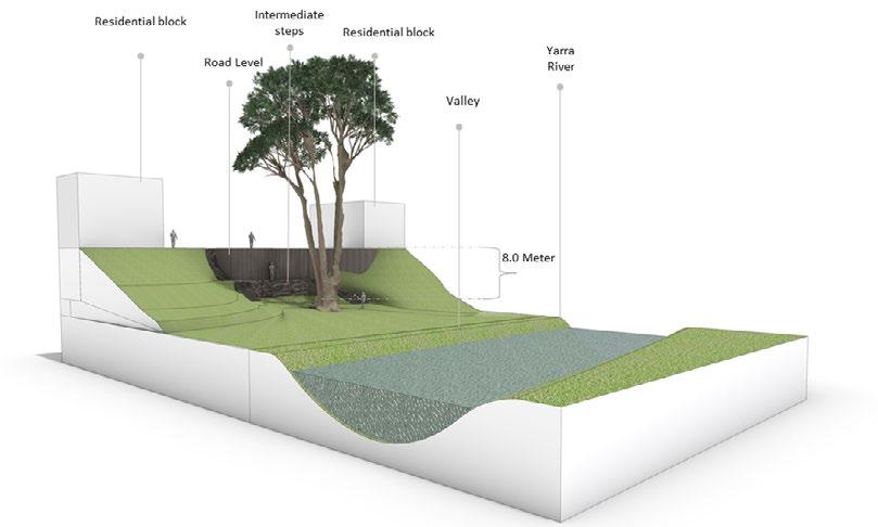
Ecological Boundary Creek RailwayFreeway
M.ARCH THESIS STUDIO Swinburne University of Technology Led by Dr Ammon Beyerle

Over the past several thousand years Kooyongkoot has gone through radical transformation in terms of resource distribution within its built environment that impacted on its ecological equilibrium. The hunter and gather community of first nation maintained their land manage ment techniques to observation and understanding of the environment, of the plants, fish, birds, insects, animals and seasons and of the varied sources of water. Industrial revolution accelerated the process of urbanization and the industrial economy dominated over the ecological priorities with lots of radical actions. Which let to unsustainable and harmful consequences such as extinction of several plants and animal species, regular flooding, high acoustic levels, raise in temperature, segregation in social and ecological connection. In present time it is our responsibility to rethinking and deep time reckoning for establishing an ecological networking for a sustainable future.
4 01
Detail Folio link: https://issuu.com/asmforhadhossain/docs/thesis_folio
KOOYONGKOOT: deep time reckonings

How
4 Ecology Social Economy
Socio-EconomicalProgress Network Sustainable
What could be the contribution of architects towards generating an ecological network through socio-ecological system for zero waste future? Generate EconomyEcology Develop socio-ecological system
What are different toolkits that would link environmental ecology to social ecology and to mental ecology? will the advanced fabrication process have an impact on developing a zero-waste ecological module?
RESEARCH QUESTION
How this contribution drives to shift the concept of industrial economy to an ecological economy?
6
1 2 3
Network Network
7

Spatial scale to develop the design strategies for future Kooyongkoot
Regenerating : KOOYONGKOOT
The above diagram explaining the way we can reckoning the scenarios of kooyongkoot, The approach would work on three threshold point in time. First regenerating an ecological network in different ecological scale, improve social engagement which will eventually creating ecological economy, The process will adapt resource optimization system for a zero waste sustainable future.

Final Iteration_Eco-Boulevard


PROPOSEDMULTIUNITMIXEDUSE OVERPASSECO CIRCULARBRIDGECONNECT STONINGTON HYDRO BOORONDARCONNECTPASSA :

Design Development
THEATREAMPHI
COMMUNITYPARKPLAYFIELD

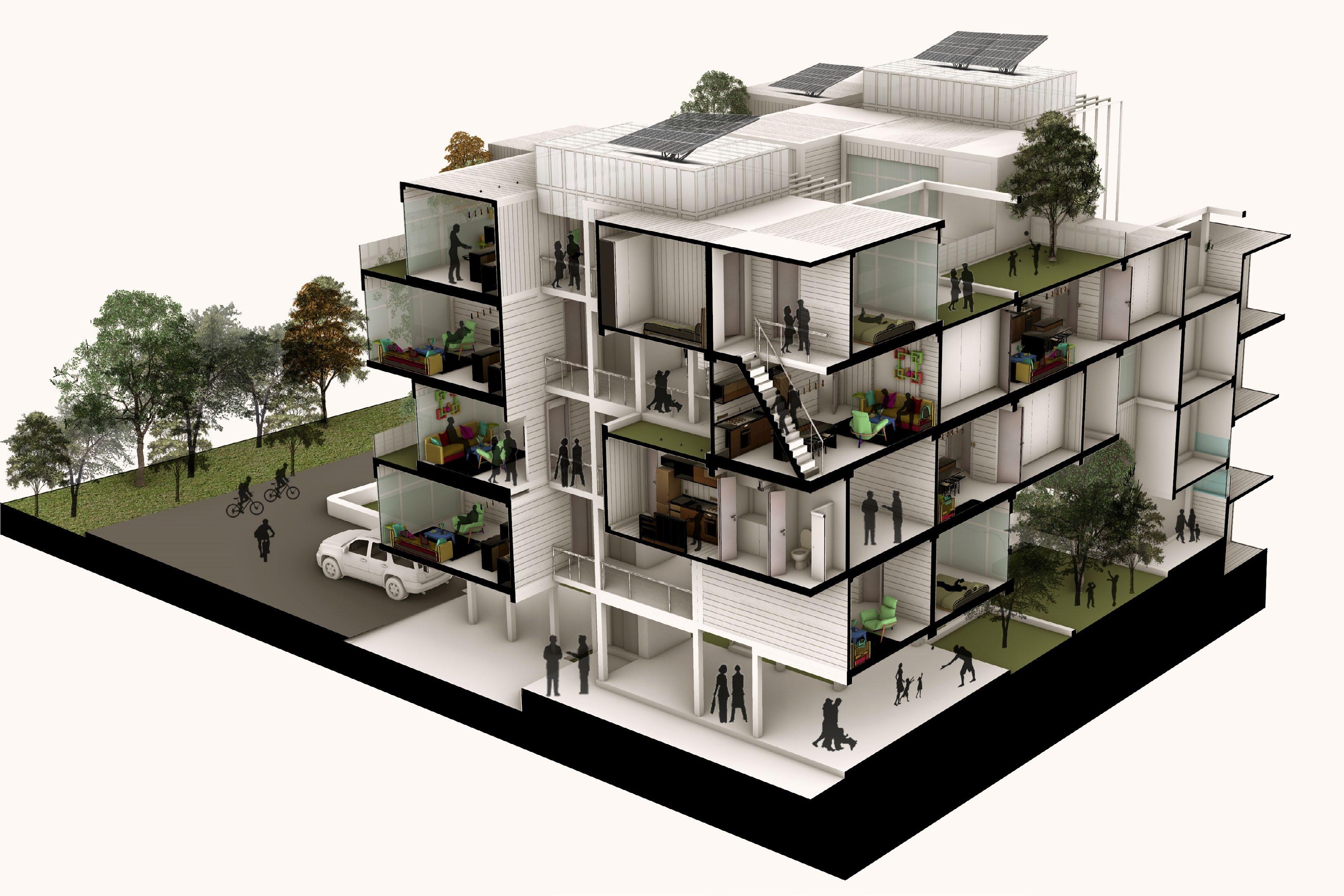
10 Three types of unit module cluster aggregation with future projected green module . Design Development: Iterations_ Developing scope of possibilities of future adaptibility or expansion Aggregation study along Eco-Boulevard . Aggregation study along Freeway Three types of unit module cluster aggregation . Different unit module cluster aggregation with future projected green module Three types of unit module cluster aggregation Different unit module cluster aggregation with future projected green module RELAXING LIVING/BEDROOM UTILITY TOILET/LAUNDRYSTAIR/KITCHEN/ 4m X 5m Module 1 BEDROOM UNIT 40 SQM +10 SQM 2ADAPTIBILITYBEDROOM UNIT 60 SQM +15 SQM 3ADAPTIBILITYBEDROOM UNIT 80 SQM +20 SQM aggregationMultipleADAPTIBILITYconstrainhelps to control the different activity space position and its future possibili ties. This constrain ag gregation also allows different contextual constrain like contour line, freeway sound wall or any other solid infrastructure or natural elements for future growth. Three types of unit module cluster aggregation Different unit module cluster aggregation with future prejected green module


Volumetric transformation for a different cluster


•
•
Visualising full context of structure
•formation4mto
Future adaptation of Green module


Three different modular 4m connection 5m to 5m connection vertical connection
11
Structural frame with vertical circulation
Volumetric transformation for a different spatialty
•

LEVEL 3GROUND A A’B’BB’BB’BPublic amenities Rentabel space Design Development : Proposed Iteration_Detail Design of Prototype SECTIONAL PERSPECTIVE ACCROSS BOULEVARD LEVEL 2


Level 1 Level 2 Level 3 Level 4 GroundRoof


15 KOOYONGKOOTACITIVATING


Individual University of Technology by Dr. Gergana Rusenova
Led
The studio invites to understand timber and reinvent the way architects design [and build!]with it by working at a rather small scale. Individually and collaboratively, we will design and partly build ... a treehouse! The treehouse is a synonym for adventure, romance and freedom. It is Wa place for adults and children to experiment with their creativity and building skills... and to play!
02
project Design Research Studio C Semester 2_2021 Master in Architecture Swinburne

Detail Folio link: arc70003-st11-2021-s2-xx-hossain_f-_project2-_porthttps://issuu.com/asmforhadhossain/docs/
Up-In-The_Air
17
18
SITE, TOPOGRAPHY & CLIMATE ANALYSIS


The location is Hawthorn East, Melbourne, Australia. The Yarra River flows near the tree where the treehouse will be built. The terrain character provides a benefit to the site by allowing it to play at different levels.

Shadow path Annual sun path Windrose

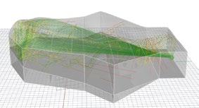
Experimenting the compact ergonomic living space by creating and studying the human figure of myself in Makehuman software.
Total six sphere of 3 meter dia generate a metaball shape

Dveloping shapes within the digitised tree using photogrammetry


ERGONOMICS STUDY
Identifying the tree geometry & space between the branches
19
TREE FORK STUDY


PHYSICAL PROTOTYPE

21
EXPLORATION OF AGGREGATION


ENVELOPE ITERATIONS

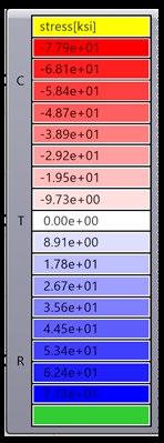
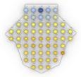
22 DISPLACEMENT AND STRESS ANALYSIS using Karambaycelium and coco coir. DISPLACEMENT MAPPING AXIAL STRESS MAPPING


23
I have used Karamba, a digital tool to analyze structural stress in support points at intersection of tree and primary structuremy celium and coco coir.


SUPPORT POINT AT INTERSECTION WITH FORM
SUPPORT POINT AT INTERSECTION WITH INTERNAL SUPPORTSTRUCTUREPOINT ANALYSIS
24
Karamba simulation
We are considering two types of connection details where the joint is pinned perpen dicular to connection plane. And another one is dowel joinery to the angular planes calculated at an intersection of both the branches.


CONNECTION DETAILS AND SRTUCTURE ANALYSIS

ROBOT SIMULATIONFABRICATION


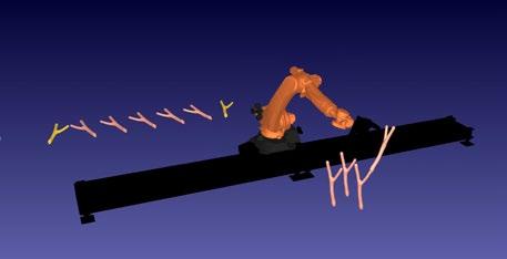
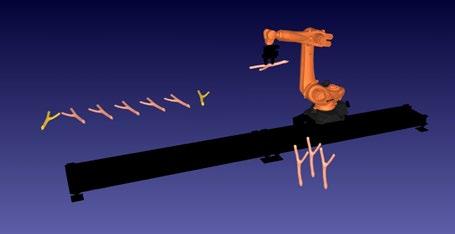

In this aggregation we are only using the same branch to simulate virtually to prove the concept. And that in real life we are hoping to use real branches all different in shape in future. Animation Link: https://youtu.be/zonqVHKI0zE
25 7531

26


PROCESSFABRICATIONONSITE


Animation link: https://youtu.be/JbPtE9lcPLMhttps://youtu.be/sVhQ6Ruuv7w


29
FROMREPRESENTATIONVISUALYARRAVALEY


WOVEN HOUSE
Group project Design Research Studio A Semester 2, 2020 Master in Architecture Swinburne University of Technology Led by Dr. Gergana Rusenova
Details Folio link: https://issuu.com/asmforhadhossain/docs/portfolioa5_print_ pages
31
03EARTH FOR THE EARTH!
This studio focus was to investigate the architectural potential of earth for the construction of contemporary housing units for three different scenarios depending on the location and inhabitants with the opportunity to explore contemporary design techniques (e.g. computational & parametric design) and the application of advanced manufacturing methods(e.g. 3D printing & robotic fabri-cation)

32
1. A Multigenerational Habitants. 2. Contextual Micro-climate and 3. Material system – inspired by indigenous culture.

Our design is integration of 3 key pillars
A homogenous space generated by a material system inspired from indigenous culture that accomodate microcilmatic environment for it’s inhabitants.
CONCEPT MAPPING
33 positioning and thickness of element can shaping a form
REINFORCEMENTMATERIALSYSTEM

need
INNOVATION INNOVATIONINNOVATION
THARMALMASS
SYSTEM CONCEPT
WEAVINGINSPIRATIONSYSTEMINSPIREDBYINDEGENIOUSCULTURE


of a centrifugal force to hold different geometrical form creating opennings by changing the pattern

LOCALYMATERIALRESOURCEDTECHNOLOGY Material systems is developed on 3 parameters –1. weaving system inspired by indigenous culture. 2. Locally resourced materials and 3. Technological interpretation. Where we are developing innovation in thermal massing, reinforcement and fabrication processes.


MATERIAL
FABRICATION
The activity mapping for multi-generational habitants where our primary focus was on identifying the interactive activities between the different generations for cohabitation. Mapping shows functional connection and the shared interactive space among those 3 generations


34
Generation 1 GRAND PARENTS


Generation 3 KIDS


MULTI-GENERATIONAL HABITANT

Generation 2 YOUNG PARENTS


4. Spatial Intervention.
STORIEDSINGLE STORIEDDOUBLE STORIEDTHREE
Generation 1_Grand Parents
Generation 3_Kids
Common spaces
1. Accommodating in single storey, double storey and 3 storey.
The spatial mapping iterations to identify the optimum solution for a multi-generational family based on the parameters


ZONING MAPPING ITERATIONS
STORIEDDOUBLEZONINGCOMPACTIN SPATIAL STORIEDDOUBLEVENTIONINTER-IN
Generation 2_Young Parents
3. View from each space and
2. Accessibility and circulation.
Taking into account the summer and winter solstice, we tried to evolve the form to see how various forms respond to the wind flow and also define the spaces at plan level within the shadow area. The diagrams show that an internal transitional space would be more effective for cross -ventilation. We can see in a 3-dimensional view, beginning from the shape of a rectangle to a form that is well ventilated throughout. We found man-made architectural interventions such as thermal mass to be put on north and west façades and then to provide wider openings to be ventilated north and west through east and south. Natural intervention such as water bodies, trees, are considered to be positioned in transitional space to minimise temperature and to create a stack ventilation system through openings on the roof. We wanted to introduce a micro-climatic immersive courtyard.


36
CONTEXTUAL MICRO-CLIMATE
1
Images prepared by Aishwarya Hippalgaonkar


37 2 3 4


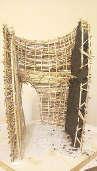
We created a 1:20 scale physical model made of bamboo that is filled with mud, with a double caged weaving structure. First of all, by anchoring it to the foundation, one layer weave pattern is created according to the shape and you can see here that the panel did not stand on itself, so we added another layer of weave pattern offset to the first one, and then both layers are cross-directionally weaved together. The outcome was optimistic that it could stand on its own. It was difficult for the next stage to render openings in such a structure. We weaved another cross-directional layer along the outline of the opening by following the existing weave. Finally, we poured mud in a thickness that could cover all layers, and it was incredible to see how 600grms of structure can hold 8 kg of wet.
1 2 3 4 5 6
PHYSICAL PROTOTYPE
38
UNDERSTANDING OF WEAVING BEAHAVIOUR WITH NATURAL MATERIAL

CONSTRUCTING DOUBLE CAGED WOVEN STRUCTURE


39 7 8 9 10
POURING EARTH INTO DOUBLE CAGED STRUCTURE


DESIGN PROPOSAL

Supporting the roof structure
GROUND FLOOR PLAN
Single module can be constructed with double caged weaved structure which is anchored to the base and partially filled with mud and another shape is branching out to create the roofing structure where wall becomes roof with introducing the different infill materials

SINGLE MODULE STRUCTURE

Generation 2_Young Parents
Roof cover (straw/ bagasse)
MULTIGENERATINAL ACTIVITY AROUND THE INTERACTIVE MICROCIMATIC COURTYARD

Thermal mass (straw/ bagasse)
Generation 1_Grand Parents
EXPLODED VIEW OF SINGLE MODULE
Generation 3_Kids
An exploded view of the module explains an overview of structural and material systems and also how a functional arrangement is possible in this sort of module.

Double caged structure anchored to base
Branching of double caged structure where wall becomes roof
41
42


44
Details Folio link: https://issuu.com/asmforhadhossain/docs/m.arch_semester_2_ folio_2021
04MOSAIC OF MUSIC
Group project Design Research Studio B Semester 1, 2021 Master in Architecture Swinburne University of Technology Led by Dr Pantea Alambeigi
This studio investigated the architectural and acoustical principles of designing a music venue featuring an auditorium for music performance that offers a live space with acceptable level of music clarity and provides even sound distribution over the audience area. It also deals with the Victorian government proposal of ”Transforming Mel bourne’s Arts Precinct”, with the aim of bringing visitors from interstate and overseas, reinforcing Melbourne’s position as Australia’s cultural capital and giving families a new public place to enjoy and explore.


Semi-Circle (Ht_12m) Convex(Ht_12m)Triangle 46.97 46.5 38.07 30.52 3.82 4.91 1.78 1.17 41.56


Geometry Rectangle(cube) Pentagon (Ht_12m) Hexagon(Ht_12m) Heptagon(Ht_12m) Triangle(Ht_12m)


Selected Geometry
3.35
Area: will be changed when varying the plan geometry

Max. SPLA 47.54 46.28 46.46 46.53 46.1 47.03 47.28
1.77 2.11 1.85 2.1 2.05 1.93 2.17 Max.
38.572.68 38.232.4 37.22.12 37.262.27 Max. SPLA 49.24 46.76 46.71 48.81 Min. SPLA 34.77 34.95 40.33 32.79 3.49 3.37
Height 12m Height 18m Height 24m
Height variation from 12m to 18m identified as an optimum range for the optimum performance.


40.782.81 40.732.61
Plan geometry: Variable
Max.
Min. SPLA 35.34 39.75 39.89 40.04 39.55 40.33 39.96 4.57 3.54 3.36 3.56 3.38 3.58
BothCeilingArea:substantial.ConstantAngle:Variablesideinclinedceiiling is choosen for optimum performance with rational volume of the geometry though down slope towards stage givce the minimum performance value.


Volume: Constant Height: Constant
Following four matrix to find the minimum rever beration time from different geometrical shape. Using grasshoper script to generate different shapes and simulating in Pachyderm plugin for Sound pressure level (SPL) value and Reverberation time (RT 30) value in color coded diagram.
2.8 41.332.7 41.232.64 41.222.7 41.062.76 41.962.6 41.282.7
UNDERSTANDING OF SOUND Avg.RT(30)SPLA3DRT(30)Avg.SPLA Variables
Avg.RT(30)SPLA3DRT(30)Avg.SPLA
1.96
Plan geometry: Constant Area: Height:constantVariable Volume: will be changed when varying the height (this helps to find the appropriate volume for your design).
Min. RT(30) RT(30) Height 6m 2.91 RT(30) 1.55 1.62 1.05 RT(30)
Matrix 3:
46
3.71 Min.
Height: Constant Plan geometry: Constant Volume: It may vary a bit when changing the angle but it’s not
Selected Geometry
Matrix 2:
Matrix 1:
Ceiling Angle: Constant Plan geometry: Constant Area: Height:ConstantConstant


Identified
Inwardsubstantial.curvedwall
Wall Angle: Variable Volume: It may vary a bit when changing the walls’ angles but it’s not


with both side inclined ceiiling is choosen for dy namic shape of thye geometry with with optimum performance value.


-
SPLA
Selected Geometry

47 Triangle Fan (Ht_12m) Horseshoe (Ht_12m) Combine(Ht_12m)shape 40.802.69 40.842.68 41.182.64 41.021.49 46.74 46.14 47.46 47.76 39.38 39.08 36.75 36.99 3.91 1.28 3.7 3.32 1.84 1.83 1.4 1.65 38.232.446.7634.953.371.55


of 38.23pa and
SPLA RT(30) through the opti peformance of sound simulation with value Rt value Matrix 4:


mum
2.4. Selected Geometry 38.112.07 38.022.48 37.112.34 38.322.58 49.65 49.45 49.42 48.9 33.22 34.78 30.99 35.45 2.62 4.2 4.53 3.22 1.64 0.83 2.92 1.7738.262.5549.4534.973.431.74 5 degree down slope towards stage 15 degree down slope towards stage 15 degree down slope towards back 5 degree down slope towards back Both side slope Avg.RT(30)SPLA3DRT(30)Avg.SPLA Variables 36.362.03 38.431.83 37.12.22 36.932.17 Max. SPLA 49.18 49.84 49.32 49.53 Min. SPLA 32.87 34.91 34.02 33.17 3.49 2.03 3.1 2.8 Min. RT(30) 1.9 1.67 1.48 1.59 Max. RT(30) outward angular wall inward angular wall outward curve wall inward curve wall
in the
FLAT ROOF AND FOOLR CURVED ROOF AND FLAT FOOLR CURVED ROOF AND SLOPE FOOLR


SECTION XX’ SECTION XX’ SECTION YY’ SECTION YY’
https://www.youtube.com/watch?v=yErni2edciQ
UtrzHG54
OVERVIEW OF RAY VISUALISATION


https://www.youtube.com/watch?v=becSE4kXPx4
48
Animate diagram


FLAT ROOF SINGLE CURVED ROOF


https://www.youtube.com/watch?v=1Ti7p_CmAK0
https://www.youtube.com/watch?v=ZLx
xy’x’ y y’x’
FORM
SECTION XX’ SECTION YY’
49 x y x x’ y’ y
RAY VISUALISATION


link: https://www.youtube.com/watch?v=yErni2edciQ
VISUALISATION PERFORMANCE


DOUBLE CURVE ROOF


FINAL
MeterMeterMeterMeter510152025Meter
Final visualisation showing the sound ray reflection occuring between the sound source and receiver in different distance starting from the stage to the back of the auditorium.

VictoriaLibraryState FlinderFedarationSquareStreetStation Shrine of remembarance SouthernstationCrossDocklands Cityroad SouthbankBlv Proposed Melbourne Art Precint


Proposing an accesssible pathway for the Southbank neighbourhood. New project is identified as an tran sitional platform for public access.
Over the tunnel try to generate an curvilinear shape to create an iconic ness of the building and also respect art center building.
Proposing an accessible tunnel and extend the graden precinct in the building


RESTAURANTVERTICLEACCESS AUDITORIUMVERTICLEACCESSPRECINCTPRPOSEDTRANSITIONAL
CONNECTIONPUBLIC
RESTAURANT AUDITORIUMLOBBY
SITE ANALYSIS
Merge the proposed garden precinct into the building in diiferent level to give a breath ing space for the people.
PLAZA ZONING VERTICAL ACCESS
51

The site selected for this project is 1 City Road, Southbank which is listed in the second phase of “Transforming Melbourne’s Art Precinct” run by Victorian government. The site is a testing ground at the moment open for creative projects and special events and it is designated for a “Center for Creativity” in the government’s phase two of the project. It is the only available land in the heart of the dense Southbank suburb, house for many art and cultural centers in Melbourne. The site potentials with the proximity and connection to the most renowned cultural centers in Melbourne, such as National Gallery of Victoria, State theatre and Arts Center Melbourne make it very interesting and challenging at the same time.

52 01000204


AXONOMETRIC VIEW SHOWING FUNCTIONAL ACTIVITYlink: https://www.youtube.com/watch?v=Ngvu5XgabIA


SHOWING DIFFERENT LEVLES

SHOWING DIFFERENT https://www.youtube.com/watch?v=iwfdo2j7XE4COMPONENTSlink:

53 FACADEPERFORATEDGLASSPRECINCTROADBETWEENCONNECTIONTUNNELAUDITORIUMCITYANDFACADEDOUBLEGLAZEDROOF EXPLODED VIEW OF DIFFERENT DESIGN FEATURES


55
PERSPECTIVESECTIONAL + 8 Plaza Level + 0 City Road + 24 The Sound Gallery

Showing the relation between different public space and also the overall performace of the building and accessibility.

ambience


Rainy night
57


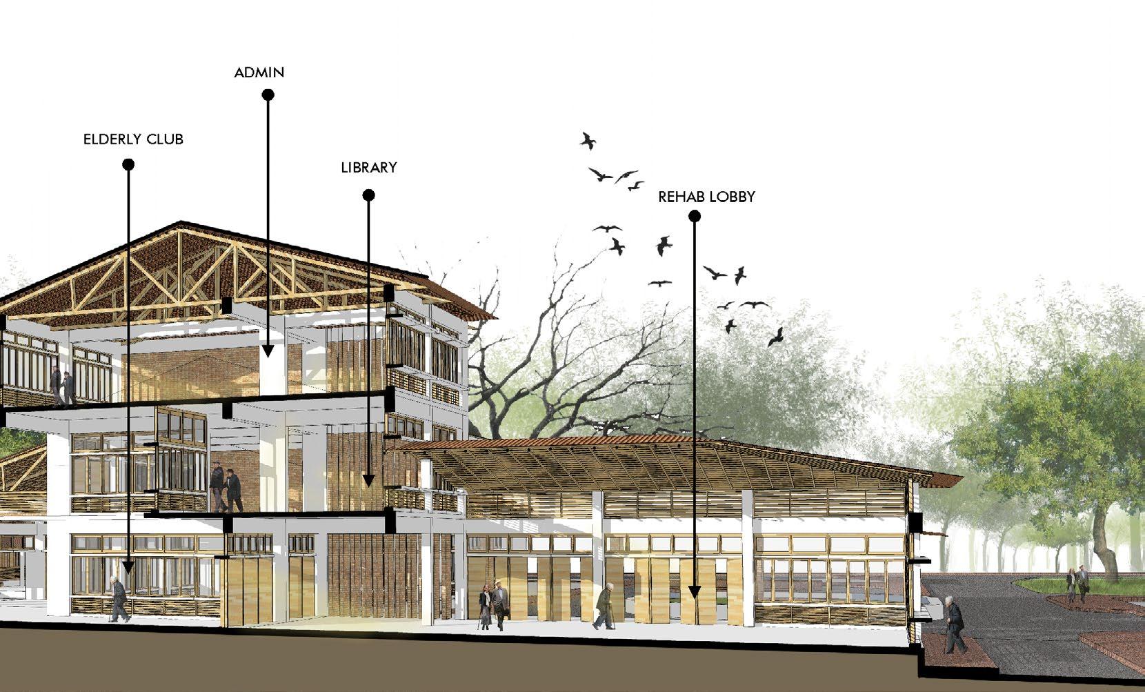
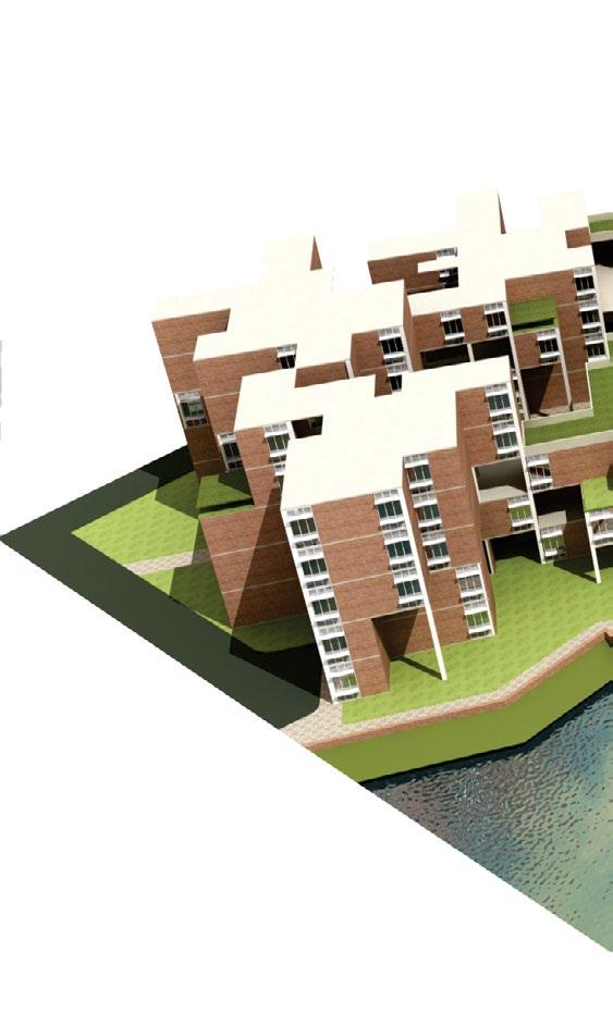
59 Final Year Thesis Project Bachelor of Architecture Bangladesh University of Technology Location : Srimongol, Moulvi Bazar, Bangladesh Duration : 14 weeks Time period : 2013-2014 Land : 5.2 Acres Floor area : 11,960 sqm Number of accomodation for long term care : 250 persons Parking : 30 cars parking for visitors & staffs OBOSHOR : SENIOR CITIZEN HEALTH CARE AND HOSPITALITY COMPLEX 05Academic Project Detail folio link: https://issuu.com/asmforhadhossain/docs/m._arch_folio_forhad_2020


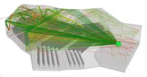
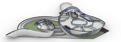
AERIAL
CONCEPT
arrangementExplainingVIEWthefunctionalandconnectivity

Idea for the morphological pattern developed through the study of local topography. Site context feeds us with lush green spaces and open green carpet in between which provides a geometrical natural grid. Primary reference for design was developed following the grid pattern.


SECTIONAL PERSPECTIVE Picturing inner court and water body

64


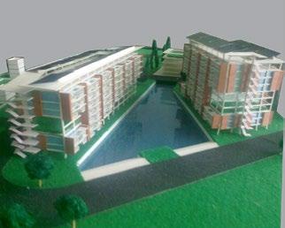
66 4th Year studio Project Group Project ( 3 members) Bachelor of Architecture Bangladesh University of Location:Gabtali-Beribandh,TechnologyDhaka, Bangladesh Time period : 2011 Duration : 8 weeks Awarded as the commendation in BERGER BEST DESIGN AWARD 2011-2012 HOUSING ACCOMODATION: FOR LOW-MIDDLE INCOME GOVERNMENT EMPLOYEES IN DHAKA CITY 06 Academic Project
67

CLUSTER ARRANGEMENT: TYPE A
CLUSTER DETAIL: TYPE A
68
CLUSTER DETAIL: TYPE B
CLUSTER ARRANGEMENT: TYPE B


MASTER PLAN


Role : Associate Architect
Location : H-07, R-17, Block-D, Banani, Dhaka-1213, Bangladesh
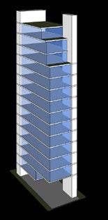
The major objective of the project was to design a luxury apartment building in a simple and solid form. The building was gracefully crowned with a rooftop garden beautifully adorned with plants and flowers. Duplex apartment unit was provided for the owner’s accommodation with office facilities and terrace garden. Split core structur al system was followed to facilitate separate accessibility in case of emergen-cy. The fire escape stair included in one of the cores was treated as an aesthetic design element on the front facade. Energy efficiency in terms of natural lighting cross ventilation, heat and sound were priori-tised in design and construction. Details Folio link: https://issuu.com/asmforhadhossain/docs/m.arch_semester_2_
CUBE INVENTURE: 15 STORIED RESIDENTIAL BUILDING07 Professional Project

70
Client : Cube Holdings Ltd.
Time period : 2014 - Under construction
Architectural Consultant : Aesthetes

3011-XA3011-X eastsouthnorth west UP LIFT
1-Y301A 301A 2.30x1.70m 2.30x1.70m 2.30x3.80m BED 6.30x4.10m 4.20x6.90m 4.30x3.60m 4.30x3.20m
a. As per Deed and inherit= 6.0 katah and 1.5 chatak =407.08 m2
FOR 18M WIDE ROAD AND 457.97 sqm LAND 6 6 TOTAL FLOOR AREA 6X407.08 m2= 2442.48 m2
3 ADDITIONAL GROUND COVERAGE parking, driveway and paved area. 101.77 m2 (25% of net land) 55.72 m2 (
1.70m TOILET 1.9x1.6m 12th FLOOR PLAN Scale1:200 TERRACE 1-Y301A 1-Y301A 3011-X3011-XA eastsouthnorth west TOILET 1.7X1.8m UP LIFT 2.30x1.70m LIFT 2.30x1.70m STAIR 2.30x3.80m UP LIVING/DINING 5.60x7.30m KITCHEN 2.9x3.40m FO. 2.30x1.60m TOILET 1.90x1.70m K.V. .90x 1.70m TOILET 1.9x1.6m FAMILY 4.20x6.90m BED 4.30x3.60m BED 4.30x3.20m LOBBY 2.90x3.6m Project Analysis PROPOSED 15-STORIED RESIDENTIAL BUILDING 1 LOCATION Road No. 17, Block No. D, Plot No. 1, Banani, Dhaka-1213 2 BUILDING OCCUPANCY TYPE A2 (Apartment building) 3 LAND AREA a. As per Deed and inherit= 6.0 katah and 1.5 chatak =407.08 m2 d. As per possession = 407.08 m2 4 ROAD WIDTH ON THE NORTH Existing road=18.29 meter 5 BASIC F.A.R FOR 18M WIDE ROAD AND 457.97 sqm LAND 6 6 TOTAL FLOOR AREA 6X407.08 m2= 2442.48 m2 Design Criteria Allowable Value Proposed Value
72 UP UP 2.30x1.70mLIFT 1-Y301A 1-Y301A 3011-X3011-XA GROUND FLOOR PLAN Scale=1:200 LOBBY2.70x3.65m 2.30x1.70mLIFT3.30x3.10mSTAIR 18.29m WIDEENTRYROAD GREEN AREA GREEN AREA GREEN AREA GREEN AREA GREEN AREA LEVEL+0.45m00 LEVEL LEVEL+.50m0000+.50m LEVEL±.00m00 LEVEL+.70m00 LEVEL+.70m00FIRE ESCAPE TOILETDRIVER'SAREA guard room 1.60x2.00mTOILET eastsouthnorth west UP UP 1-Y301A 1-Y301A 3011-X3011-X 1st FLOOR PLAN Scale 1:200 LOBBY2.70x3.65m ROOMELECTROMECHANICAL4.30x9.79m COMMUNITY ROOM 4.20x7.00mVER.4.20x2.3m eastsouthnorth west UP 2.30x1.70m2.30x3.80mSTAIRLIFTLIFT2.30x1.70m LEVEL+2.86ROOFm LEVEL+3.35ROOFm UP 2nd,3rd,4th,5th,6th,7th,8th & 9th FLOOR PLAN Scale 1:200 1-Y301A 1-Y301A 3011-XA3011-XA LIFT 2.30x1.70m LIFT 2.30x1.70m eastsouthnorth west STAIR 2.30x3.80m UP BED 5.10x4.10m TOILET 1.6X1.7m FAMILY 4.20x6.90m BED 4.30x3.60m BED 4.30x3.20m LIVING/DINING 5.60x7.30m KITCHEN 2.9x3.40m FO. 2.30x1.60m LOBBY 2.90x3.6m TOILET 1.90x1.70m K.V. .90x 1.70m TOILET 1.9x1.6m
BED
PLAN Scale1:100
3 LAND AREA
1-Y
STAIR
2
d. As per possession = 407.08 m2 ROAD WIDTH ON THE NORTH Existing road=18.29 meter BASIC F.A.R
Design Criteria
as per FAR) 2419.24m2 (Without any Exemption) 2 MAXIMUM GROUND COVERAGE 203.54 m2 (50% of net land) 197.69
PROPOSED 15-STORIED RESIDENTIAL BUILDING
UP
Allowable Value Proposed Value Exemption (48.56% of Area) 13.69 Land 37.75%
Land
LIFT
KITCHEN
TOILET
Project Analysis
1 LOCATION Road No. 17, Block No. D, Plot No. 1, Banani, Dhaka 1213 BUILDING OCCUPANCY TYPE A2 (Apartment building)
5
of Land Area) 5 FRONT BALCONIES (30% OF FRONT x 1m x 14)=2.685X1X 0.3X 14= 11.277 sqm 1.7 sqm 6 SIDE & BACK BALCONIES 2.5% OF FLOOR AREA =61.062 36.4 sqm 7 NUMBER OF STORIES and APERTMENT 15 stories and 14 Apartments 8 CAR PARKING Minimum 2 car for every 3 Units=9.66 Maximum Car Nos=11X1.5= 16.5 nos 12 nos
10th & 11th FLOOR
BED
1 TOTAL FAR INCLUDED AREA 6X407.08 m2= 2442.48 m2 (Without any
LIVING/DINING 5.60x7.30m 2.9x3.40m 2.30x1.60m 2.90x3.6m 1.90x1.70m K.V. .90x
4
FO.
LOBBY
TOILET 1.6X1.7m FAMILY
Area) 4 MANDATORY GREEN AREA 101.77 m2 (25% of net land) 153.67 m2 (
% of
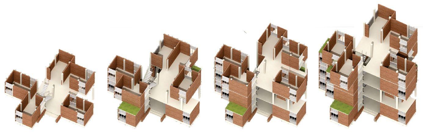
Allowable volume Split core system Shell for heat insulation Split shell for openings Perforated shell for light and ventilation 13th FLOOR PLAN Scale1:200 1-Y301A 1-Y301A 3011-X3011-XA eastsouthnorth west UP STAIR 2.30x3.80m LIFT 2.30x1.70m LIFT 2.30x1.70m UP LOBBY 2.90x3.6m FO. 2.30x1.60m TOILET 1.9x1.6m K.V. .90x 1.70m TOILET 1.90x1.70m KITCHEN 2.9x3.40m LIVING/DINING 5.60x7.30m BED 4.30x3.20m FAMILY 4.20x6.90m BED 4.30x3.60m TOILET 1.7X1.8m 14th FLOOR PLAN Scale1:200 LIVING4.6x6.9m LOBBY2.70x3.65m OPEN 4.9x3.9mKITCHEN 1-Y301A 1-Y301A 3011-X3011-X eastsouthnorth west 2.30x3.80mSTAIR DN 6.7x5.9mBED-1 UP DINING2.30x1.70m2.30x1.70mLIFTLIFT4.9x3.9m ROOF PLAN Scale1:200 DN 1-Y301A 1-Y301A 3011-XA3011-X LOBBY 2.70x3.65m MACHINE 2.80x3.30mROOM LEVEL 15 +48.9 m LEVEL 14 +45.7 m eastsouthnorth west LIFT 2.30x3.50m UP LEVEL 15 +49.5 m LEVEL 15 +48.9 m GENERATION OF FORM


A roof garden vibrant with flora and fauna was gracefully situated at the top of the building, perceived as a natural retreat from the bustling urban life. The garden is covered with a concrete shell, slit in a regular stripe pattern to allow adequate sunlight and rainwater. Vines twining along the concrete shell add subtle softness to the hard surface. An artificial stream falls from the wall forming a water cascade around the seating space creating a soothing environment. Slit openings on the east and west side act as vertical lou-vers for sunlight offering a grandiose view of the cityscape.
47.94m 53.50m WAST ELEVATION SCALE=1:300 LEVEL+0.5m00 +53.1 m LEVEL LEVELLEVELLEVELLEVELLEVELLEVELLEVELLEVELLEVELLEVELLEVELLEVELLEVEL+3.7m0103+10.1m04+13.3m0516.5m06+19.7m07+22.9m08+26.1m02+6.9m09+29.3m10+32.5mLEVEL11+35.7m12+38.9m14+45.3m13+42.1mROOF+48.5m LEVEL+0.0m00 2.40m 1.78m 3.17m 3.17m 3.17m 3.17m 3.17m 3.17m 3.17m 3.17m 3.17m 3.17m 3.17m 3.17m 3.57m 3.17m 4.56m LIGHTNING ARRESTER 5.56m LEVEL+0.5m00+53.1LEVELLEVELLEVELLEVELLEVELLEVELLEVELLEVELLEVELLEVELLEVELLEVELLEVELLEVELLEVELm01+3.7m03+10.1m04+13.3m0516.5m06+19.7m07+22.9m08+26.1m02+6.9m09+29.3m10+32.5m11+35.7m12+38.9m14+45.3m13+42.1mROOF+48.5m LEVEL+0.0m00 53.10m 0.50m 2.80m 0.20m 3.00m 0.20m 3.00m 0.20m 3.00m 0.20m 3.00m 0.20m 3.00m 0.20m 3.00m 0.20m 3.00m 0.20m 3.00m 0.20m 3.00m 0.20m 3.00m 0.20m 3.00m 0.20m 3.00m 0.20m 3.00m 0.20m 3.00m 0.20m 2.80m1.80m SECTION -X1 SCALE=1:300 BEDFAMILYLIVING/DININGFO.LOBBY BEDFAMILYLIVING/DININGFO.LOBBY BEDFAMILYLIVING/DININGFO.LOBBY BEDFAMILYLIVING/DININGFO.LOBBY BEDFAMILYLIVING/DININGFO.LOBBY BEDFAMILYLIVING/DININGFO.LOBBY BEDFAMILYLIVING/DININGFO.LOBBY BEDFAMILYLIVING/DININGFO.LOBBY BEDFAMILYLIVING/DININGFO.LOBBY BEDFAMILYLIVING/DININGFO.LOBBY FAMILYLIVING/DININGFO.LOBBY VERFAMILYLIVING/DININGFO.LOBBY LIVING/DININGFO.LOBBY LIGHTNING ARRESTER 1.00m2.20m1.00m3.20m3.20m3.20m3.20m3.20m3.20m3.20m3.20m3.20m3.20m3.20m3.20m2.35m 0.05m0.80m 3.30m1.00m2.20m 0.30m 2.40m0.20m Planter Box Planter Box Planter Box 0.50m 2.90m
A flourishing roof garden doesn’t merely enhance the overall aesthetic, green roofs also improve a build-ing’s environmen tal performance, thermal insulation and climate responsiveness.


LEVEL+0.5m00 LEVEL+3.7m01 LEVEL 03 +10.1 LEVELLEVELLEVELLEVELLEVELLEVELLEVELLEVELLEVELLEVELm04+13.3mLEVEL0516.5mLEVEL06+19.7m07+22.9m08+26.1mLEVEL02+6.9m09+29.3m10+32.5m11+35.7m12+38.9m14+45.3m13+42.1mROOF+48.5m LEVEL+0.0m00 0.20m 0.20m 3.00m 0.20m 3.00m 0.10m 3.00m 0.20m 3.00m 0.20m 3.00m 0.20m 3.00m 0.20m 3.00m 0.20m 3.00m 0.20m 3.00m 3.00m 4.30m LIGHTNING ARRESTER NORTH ELEVATION SCALE=1:300 0.20m 3.40m 0.20m 0.30m 0.10m 3.05m 3.00m


Parking : 16
08 Professional Project
The fast-paced commercial growth of Dhaka city demands new business strategies to cope with changing consumer practices. The project initiates a shared facility between a car showroom owned by OVI Trading and Peyala restaurant with an aim to support each other’s business through addressing a larger consumer group. Primary consumers visiting the Car Showroom can inadvertently become interested to spend some time in the adjacent restaurant and vise-versa. Fostering this idea, MGH Group developed the commercial facility for OVI trading & Peyala restaurant as a lease for 5 years in a prime commercial location in Dhaka.
Architectural Consultant : MGH Architects Location :
76
Single
Role : Project Architect CAR SHOWROOM
: OVI Trading & MGH Restaurant Pvt.
Land
Client Ltd. Plot-01, Road-49, Gulshan-2, Dhaka-1212, Bangladesh : 2016 - 2017 area : 1475.91 sqm floor area : 780.00 sqm : storied with a mezzanine floor Nos WITH BUILDING

Total
RESTAURANT:COMMERCIAL
Time period
Number of stories

78 Car Showroom with Restaurent, Gulshan 49, Dhaka 1213 CHECKEDENGINEER: CONSULTANT:DRG. TITLEARCHITECTS: PREPARED BYCLIENT:PROJECT 26 - 11 2016 02. AR. Muhammad Abu Zobayer Riyal 01. AR. A S M Forhad Hossain Architects MGH Group Mohammad Anisur Rahman CONSTRUCTIONISSUEDFOR A S M Forhad HossainNorth & ElevationSouth DATE SOUTH ELEVATION 1 2 4 5 6 73 1 2 4 5 6 73 20' 20'20'4' 20' 20' 20' 4' 128' SCALE = 1: 150 1 2 4 53 1 2 4 5 6 73 20' 20'20' 20' 20' 20'4' 4' 128' NORTH ELEVATION SCALE = 1: 150 Car Showroom with Restaurent, Gulshan 49, Dhaka 1213 CHECKEDENGINEER: DRG.NOCONSULTANT:DRG. TITLEARCHITECTS: PREPARED BYCLIENT:PROJECT 26 - 11 2016 02. AR. Muhammad Abu Zobayer Riyal 01. AR. A S M Forhad Hossain Architects MGH Group Mohammad Anisur Rahman CONSTRUCTIONISSUEDFOR A S M Forhad HossainNorth & ElevationSouth DATE SOUTH ELEVATION 1 2 4 5 6 73 1 2 4 5 6 73 20' 20'20'4' 20' 20' 20' 4' 6'-10"8' 128' 6'-6" SCALE = 1: 150 1 2 4 5 6 73 20' 20'20' 20' 20' 20'4' 4' 128' NORTH ELEVATION SCALE = 1: 150 Landscape EntryWaterbodyroad Parking area Green area Windflow and Sunpath diagram Wind Sunpathflow Functional ArrangeCar Restaurantshowroom SuperUtility roof Site Orientation Building Orientation Functional Zoning ORIENTATION AND ZONING GROUND FLOOR PLAN


79
RCC column-beam foundation with integrated anchor bolt for steel su perstructure & brick foundation for mezzanine floor

Pre-fabricated steel super structure erectected from plinth level


STRUCTURAL FABRICATION SYSTEM
Pre-fabricated curtain glass wall installation around super structure


Pre-fabricated corrugated commercial sheet installation over super structure


24

80 L-22L-47L-46L-45L-44L-43L-42L-41L-40L-39L-38L-37L-36L-35L-34L-33L-32L-31L-30L-29L-28L-27L-26L-25L-24L-23L-21L-20L-19L-18L-17L-16L-15L-14L-13L-12L-11L-10L-9L-8L-7L-6L-5L-4L-3L-2L-15''slab+6'' skirting L-22L-47L-46L-45L-44L-43L-42L-40L-39L-38L-37L-36L-35L-34L-33L-32L-30L-29L-28L-27L-26L-25L-24L-23L-20L-19L-18L-17L-16L-15L-14L-13L-12L-10L-9L-8L-7L-6L-5L-4L-3L-2L-1L-11L-21L-31L-41 5'' slab+6'' skirting1'-3"2'-6"4'-6"5'11"5"5'' drive way slab 15'' wall from drive way to slab bottom 1'-3"11"2'-6"4'-6"5'5" 5'' drive way slab 15'' wall from drive way to slab bottom 8'4'-1"5'' hidden slab 5'' hidden plinth slab 8'4'-1" 5'' hidden slab 5'' hidden plinth slab WALL- B-1 WALL- B-2 ELEVATION -B1 & B2 L-48 L-48 Firstclass machine cut Brick works with fine pointing 3'-9" 5'-9" 5" 2'-10"2'-6"2'-1" 2'-1" 5" 3'-10" 6'3'-8"7'-9" 3'3'-6"10" 9'-7" 2'-1"10"10'1'-8" 10"10"10"10"10"4'-2" 4'-7" 10" 10" 10" 5' 10" 10" 10" 10" 10" 10" 10" 4'-2" 5'-5" 5'-5" 15' 10" 7'-11" 5" 5" 4'-3" 3'-5" 1'-8"10"10"10"2'-11" Rainwater pit 1'-3" 1'-3" 3'-8"4'-6" 5"5" 1'-8" 1'-3" 6'-3" 5' 5" 5'-5" 5" 2'-6" 5" 3'-6" 5" 1'-1" 5'-5" 10" 0" 10" 5" 3'-9" 2'-9" 5" 1'-3" 2'-6" 2'-6" 1'10"5" 1'-6" 8'-4"5'5"5" 7'-1" 3'-5" 10"10"10" 6" 6" 8' 10" 12'6"7" 4'-10" WALL- A WALL- B-1 WALL- B-2 WALL- D WALL- C WALL- EE'EA'A C'C DD' 3'-4" 13'-4"F'F 3'-4"1'-8" 0204 03 10" 4' 10" 4'-1" 10" 4' 1'-6" 8'-5"10'-8" 10"3'-7" 5" 7' 10" 10''x3'' c/c brick elevation 10'' 3''324'' 9 21'' 5'' 3'' 4 21'' 324'' 910''12''142 5''x3'' c/c brick elevation 10''x5'' c/c brick plan 5'' 5'' 4 21'' 142 5''x5'' c/c brick plan UTILITY AREA BRICK LAYOUT PLAN SITE PREPARATION Demolished old structure and cleaned some small trees and bushes. Filled with filling sand up-to 5’0’’ and compcted with water and compact vibrator. RCC culumn and retainingbrick wall at the lake side of the site to hold the filling sand in rainy season. Firstclass machine cut Brick works with fine pointing 3'-9" 5'-9" 5" 2'-10"2'-6"2'-1" 2'-1" 5" 3'-10" 6'3'-8"7'-9" 3'3'-6"10" 9'-7" 2'-1"10"10'1'-8" 10"10"10"10"10"4'-2" 4'-7" 10" 10" 10" 5' 10" 10" 10" 10" 10" 10" 10" 4'-2" 5'-5" 5'-5" 15' 10" 7'-11" 5" 5" 4'-3" 3'-5" 1'-8"10"10"10"2'-11" Rainwater pit 1'-3" 1'-3" 3'-8"4'-6" 5"5" 1'-8" 1'-3" 6'-3" 5' 5" 5'-5" 5" 2'-6" 5" 3'-6" 5" 1'-1" 5'-5" 10" 0" 10" 5" 3'-9" 2'-9" 5" 1'-3" 2'-6" 2'-6" 1'10"5" 1'-6" 8'-4"5'5"5" 7'-1" 3'-5" 10"10"10" 6" 6" 8' 10" 12'6"7" 4'-10" WALL- A WALL- B-1 WALL- B-2 WALL- D WALL- C WALL- EE'EA'A C'C DD' 3'-4" 13'-4"F'F 3'-4"1'-8" 0204 03 10" 4' 10" 4'-1" 10" 4' 1'-6" 8'-5"10'-8" 10"3'-7" 5" 7' 10"


while PEYALA used as lounge.
81 CONSTRUCTION FLOWCHART SUPERSTRUCTURE LANDSCAPE INTERIOR 25% of land left soakable open green area and soft pave area for parking to penetrate theVegetationrainwater.onlakesideand near entry gate. +3'-0" 17'-2" 13'-0210'-6122'-1112113'-0210'-622'-1112 12'-112 111'-32 12'-112 12'-82 111'-32 13'-22 9'-5" 4'-4"4'-3"4' 4'-212 SOCKET 4 SOCKET 4 SOCKET 4 SOCKET SOCKET4 SOCKET SOCKETSOCKET 5'-11"5'-3"5'-4" 6'5'-11"5'-3" 16'-6" 10 SOCKET 192 sink line normal) purifier line 2- network2- network +3'-6" A-02Showroom with Restaurent, Gulshan 49, Dhaka 1213 CHECKED DRG.NOCONSULTANT:DRG. TITLEPREPARED BYCLIENT:PROJECT 26 11 2016 Architects MGH Group CONSTRUCTIONISSUEDFOR A S M Forhad Hossain LAYOUTFOUNDATION,COLUMN&GRADEBEAM DATEENGINEER:ARCHITECTS: 02. AR. Muhammad Abu Zobayer Riyal 01. AR. A M Forhad Hossain Mohammad Anisur Rahman B.Sc Engr.(Civil), MIEB, DMINB/CE A.N.M KHALED B.Sc Engr.(Civil), MIEB, DMINB/CE U.G.R F-1F-3F-2 F-1 F-1 F-1 F-1 F-2 F-1F-2 F-1 F-1 F-1 F-1 F-1 F-3 F-3 F-3 GB GB GB GB GB GB GB GB GB GB GB GB GBGB GBGB GBGBGBGB 04 07 CA 01 02 03 05 06 B 04 0701 02 03 05 06 CAB 20' 20' 20' 20' 20' 20' 3'-6"3'-6" 127' 3'-6" 20' 20' 20' 20' 20' 20' 3'-6" 127' BRICK FOUNDATION C-1 C-1 C-1 C-1 C-1 C-1 C-1C-1C-1C-1C-1C-1C-1C-1 C-2 C-2 C-2 C-2 FOUNDATION, COLUMN AND GRADE BEAM LAYOUT I section steel col umn and corrugatedfabricationbeam,sheet roofing with glass wool insulation. Brick wall and concrete slab for mezzanine foor areas A green wall with a touch water pool and fountains introducedarewith a signedge.Saved 8 exsiting big trees by design.


Two tenure engaged separtely for finishing and furnishing tradingthemselves.forOVIused mazzanine floor for small office

KITCHEN HOOD
82 OPEN KITCHEN 1 1 2 3 4 5 6 7 8 7 High stool seating8123 Condiment station 654 Desert station Coffee stastion 7 Hot Ice-creamChillerkitchenstationPOScounter
Spatial characteristics of Peyala cafe FITOUT AND FINISHES


Two separate motor are used for inlet cool air and outlet hot air. The range of the suction fan can be adjustable to collect hot fume only from the kithen area as the area covered with VRF sysytem.

Cylindrical shaped inddor unit used with central VRF outdoor unit
VRF SYSTEM

FURNITURE


Hollow metal box used for frame Teak plywood with clear polish and rectangular cusion.
83

84 1 3 2 4 5 6 7 8 9 10 321 Drive through road VRF system Rainwater gutter 654 Surface drainParkingMezzanine seating 7 Open kitchen 8 Toilets 9 Entry 10 POS counter Exhaust 11 Main road12 12 SECTIONAL DIAGRAM LEGENDS


86
PHYSICAL MODEL MAKING


87 PROFESSIONALAND COMPETITION


August 2022 A S M Forhad hosssainforhad@gmail.comHossain
