5 minute read
InfraWorks Putting it All Together

from AUGIWorld
by AUGI, Inc.

PRODUCT FOCUS InfraWorks
Putting it All Together
How many times have you heard this statement: “Autodesk InfraWorks is an aggregator of data, and there is nothing like it!” …I remember the first time I heard it a few years ago. And from that day, I decided to jump into this world of possibilities offered by this fantastic program to help put massive amounts of data into the context of a full infrastructure project. So, let’s dig into how this can be achieved within our Autodesk world.
POINT CLOUD FILES:
With all the discussion about UAVs and photogrammetry, how can we use the power of InfraWorks to add this data into our existing model? Whether you have processed the information yourself, or it has been given to you, one of the most common files you may have obtained/received will be an .las extension file. Here you will use the power of ReCap Pro to produce a clean and adjusted .rcp point cloud.

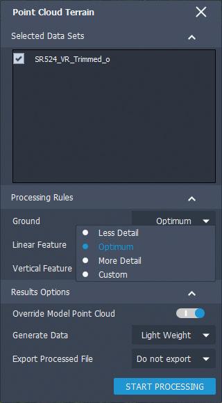
1. Within the data sources, add the point cloud. Close and refresh (make sure your coordinate systems are a match from the .rcp file and the InfraWorks model). 2. Create a point cloud theme (elevation preferably) to verify the point cloud data. 3. Depending on your project’s scope, and the quality of the data collected, you may use vertical feature extraction to locate elements such as powerlines, mailboxes, signs, etc. This feature is an excellent tool! Unfortunately, I see users frequently underestimate its value. 4. Now it is time to generate the existing surface that this point cloud can provide.
InfraWorks PRODUCT FOCUS

PRODUCT FOCUS InfraWorks

For transportation projects, nothing can explain what our projects are, better than a visual representation within the site context. Here are a few basic steps to keep in mind: 1. Assign render materials to your desired link codes in your corridor model within the settings of the code set style you are using for your project. Please remember that when we attach this Civil 3D model to InfraWorks, any link code containing a render material will create a coverage area in our InfraWorks model based on the link style name assigned. 2. Now that our C3D corridor is good to go, we can then move into InfraWorks and access the style rules dialog box to access the coverage areas tab. You will select all the default rules and delete them. This allows us to create our own based on the C3D corridor. 3. Proceed to attach the C3D file within the data sources panel. When prompted, select the corridor surface, and the corridor coverages displayed in the choose data sources window. Click OK. 4. Now refresh these two new elements in your model; the terrain, and the coverage areas. Don’t worry as you won’t see anything displayed yet. For that, let’s go to step 5. 5. Let’s go back to our style rules in the coverage areas tab. We will see the custom style rules that were created based on our link codes assigned in the C3D corridor. Assign materials as needed, and then hit Run Rules to apply these materials to these coverage areas.

3D ELEMENTS 1. As an aggregator of data, InfraWorks allows us to bring several types of 3D files into our models, such as .obj, .dae, .fbx, .dxf, and .3ds. I encourage you to create your own content and customize it to the needs of your project’s scope. Parametric modeling is an amazing and practical skill I advise many modelers to acquire. Interactive placing is an effective way to bring many of these elements in, while not compromising the accuracy and context of what you want to show. 2. Revit elements can be attached to the InfraWorks model the same way. Make sure that if your Revit model is geolocated, the coordinate system and units are a match to the model properties in the InfraWorks environment. 3. 3ds Max is perhaps one of the most underused tools in the AEC Collection due to the learning curve many people think they need to follow. The combination of InfraWorks and 3ds Max can provide realistic detail for projects that makes them come alive for clients and stakeholders. Autodesk University 2019 had great presentations on this topic. I encourage you to watch sessions CS323313 and CES322532, where you can view the full potential of what you can achieve using this powerful software.
https://www.autodesk.com/autodesk-university/ au-online?facet_event[0]=Las%20Vegas&facet_ year[0]=2019&facet_product[]=urn:adsk. content:content:0e1af96b-7177-4568-b328-58a2c7ff4ba9
OTHER ELEMENTS
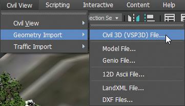
The process to import other extension files is similar. This can be achieved by following the prompts provided by the data center tabs, depending on the type of file you wish to attach. There are many more processes we could discuss using different project scopes and context - to mention just one: “Virtual Reality”. I don’t want to leave you hanging here, so I encourage you to check out this interesting workflow from John Sayre from a few years ago. This demonstration will show you another incredible potential use in design visualization.
https://www.youtube.com/watch?v=fJ0HTJkOy2Y
Happy modeling everyone, and don’t hesitate to email me with questions! I am glad to help.
Oscar Castaneda, PE, is a transportation planning and design engineer for CONSOR Engineers, with an office in Winter Springs, Florida. As a 3D roadway engineer, Hhis 3D design expertise is demonstrated by his selection as an instructor at the past four Florida DOT Design Expositions. With more than 15 years of industry experience, he has led the charge for a seamless, highly beneficial integration of cutting-edge 3D technology into the firm’s design techniques, process, and product. You can reach Oscar for questions and comments at: ocastaneda@consoreng.com


