2 minute read
3ds Max

from AUGIWorld
by AUGI, Inc.

3ds Max PRODUCT FOCUS by: Brian Chapman 3ds Max Pro Tip: Use Custom Modifiers 3ds Max by: Brian Chapman
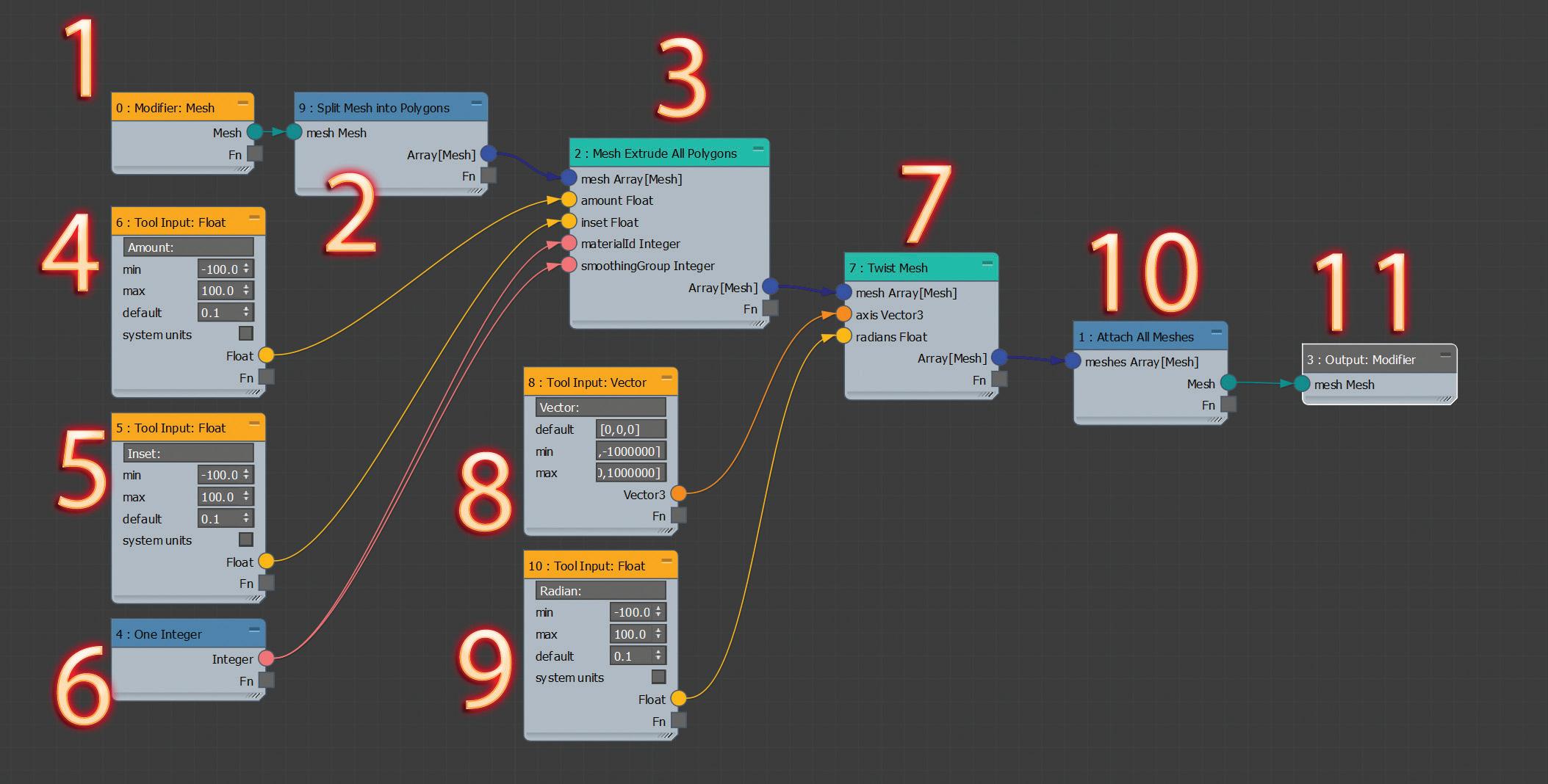
Figure 1 – Max Creation Graph Example
Warning! Experimenting with the creation of custom modifiers using the Max Creation Graph can lock up a file in an endless broken loop, which will cause it not to open. If that happens, delete the custom modifier from this location: C:\Users\[user name]\ Autodesk\3ds Max XXXX\User Tools\Max Creation Graph\ Tools. Deleting the tool should allow you to open the file.
With 3ds Max, we can build custom modifiers. We can use this feature for the construction of procedural buildings, randomization of materials, animation, and more. There’s no limit to the modifications and inputs we can add. Additionally, we can eliminate steps we traditionally take through the modifier stack by combining actions into a single custom tool. For example, by combining inset, extrude, and twist into a single modifier that I created, and named "AUGI_Example". I generated all of the complex geometry displayed in Figure 2 in a matter of just a few minutes.

3ds Max PRODUCT FOCUS
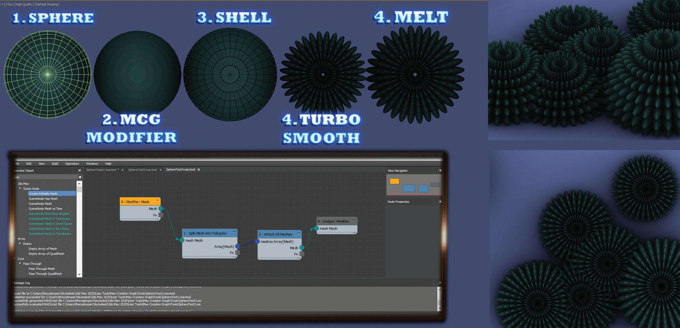
Figure 3 – Custom Modifier in Stack
The simplest way to start experimenting with the creation of custom modifiers is to insert a sphere (or similar object). Then, with the sphere object selected, pick the Create and Apply MCG Modifier option in the Scripting menu. Selecting the option will open the MCG editor, and simultaneously apply a generic graph based on the name you give it. To get you started, I’ll explain the modifier I created based on the numbers displayed in Figure 1. In addition to creating our custom modifier, we can apply additional modifiers to them. Figure 4 demonstrates a complex object created using a very simple node system that splits the mesh into individual polygons. I then applied the modifiers Shell, Turbo Smooth, and Melt. Doing this, it created the result in the final object displayed in Figure 4.
1 (Modifier:Mesh) – The base mesh. This node represents the object in our scene before opening the editor.
2 (Split Mesh into Polygons) – I used this node to split my original sphere into individual faces. The node then outputs a collection of all the faces as individual entities I can influence.
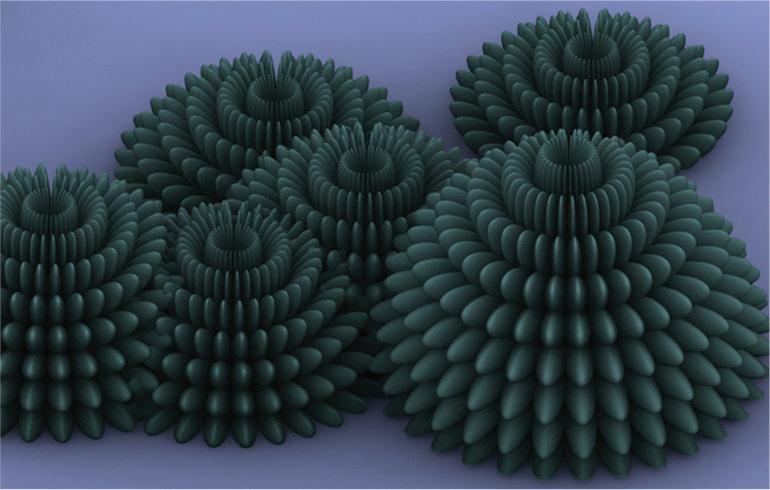
3 (Mesh Extrude All Polygons) thru 6 – These nodes allowed me to apply extrusion options to each of the individual faces by feeding in the collection mentioned above. This node requires user input for the amount of extrusion as well as an inset. To accomplish this, I applied two “Tool Input: Float” nodes. Float refers to the value/ number format (as in floating-point format). The extrusion node also requires values for the Material ID and Smoothing Group. So, I applied a “One Integer” node to both. Figure 4 – Complex Object Created using the MCG Editor
7 (Twist Mesh) thru 9 – The Twist Mesh Node requires user input for the axis of the twist as well as the amount of twist (in radians).
10 (Attach All Meshes) – After applying the various steps mentioned, I reattached everything.
Brian Chapman is an Autodesk Authorized Developer and CAD Applications Specialist for Westwood Professional Services. Brian can be reached at procadman@pro-cad.net. You can review some of his personal work at emptypawn.com and procad.blog


