
15 minute read
BIM 360 Cloud-based Solutions with BIM 360

from AUGIWorld
by AUGI, Inc.

Cloud-based Solutions with BIM 360
➲ A utodesk’s BIM 360 is a cloud-based solution that is designed to manage a project from start to finish. As part of Autodesk’s Construction Cloud, BIM 360 helps deliver a complete project lifecycle solution. But what is it? BIM 360 is a collection of Modules and each Module is a solution. In order for all of the Modules and other Construction Cloud solutions to speak to each other, Autodesk uses a common Application Programming Interface – or API – called Forge. Forge creates the unified platform that is BIM 360 Next Generation. The foundation “module” that all the solutions within BIM 360 live on top of is BIM 360 Document Management. That is where you will find BIM 360 Model Coordination. Model Coordination reads the models it is to clash, based on the folder within Document Management. Figure 1 Model Coordination can now read folders placed in both Plans and Project Files locations! This means design teams can now coordinate their working, live models at the start of the project

with little extra effort and a few licenses of BIM 360 Coordinate. In this article we are going to focus on BIM 360 Model Coordination with an overview from set up to managing models to working with clashes.
A BRIEF OVERVIEW OF BIM 360
BIM 360 is one part of the Autodesk Construction Cloud. While other aspects of the Construction Cloud also work in various phases of a project, this article is focused on the BIM 360 component.
Figure 2 An overview of all modules and a brief description of what they do
and what they are also known as.
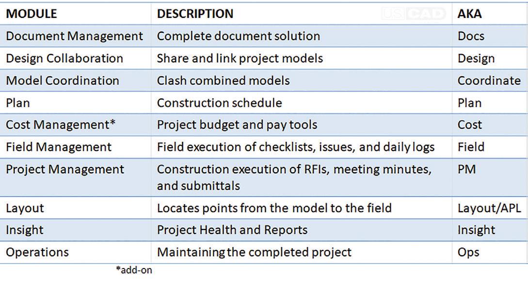

Figure 4
Each Module is designed to work at different points in the project lifecycle with all of them interacting with Document Management throughout the entire process. Coordination typically is focused on subcontractor or fabrication models but has grown to help designers with their design models.
The Project Admin Module is where setting up the Coordination Spaces for Model Coordination happens. While the Document Management Module is where Model Coordination will read the models from as well as feed issues to the model.
NEXT GEN MODEL COORDINATION
Navisworks Manage has been the main tool in Autodesk’s wheelhouse for Clash Detection. With BIM 360 Classic – the first cloud solution – BIM 360 Glue was introduced. While it had its positives and its negatives, it was a viable solution that as many adopted as rejected. After all, it is hard to please an industry notorious for the slow integration of technological change.
With BIM 360 Next Gen, living on top of the Forge platform, it seemed like cloud solutions were finally poised to take the construction world by storm. With the announcement of Model Coordination, many were expecting a melding of the best of Navisworks with the compatibility of Glue. It quickly developed the nickname Glue 2.0 following the adoption of Field 2.0 and other Nest Gen versions of BM 360. Autodesk and Beta Testers were quick to point out that Model Coordination was a ‘reimagination’ of Clash Detection.
The Next Generation of Model Coordination started at the ground level: what are you clashing and why? Putting in some Machine Learning, Model Coordination was born. It would take the models in a location and clash them against each other and automatically grouping the results. The automatic grouping here saves many hours for every Clash Report that must be created compared to Navisworks. From here, new features get layered in; assigning and tracking clashes through Issues, what to group clashes by, and tools to review the model. More workflows and features come out with every release, including tying BIM 360 Issues to Navisworks.
GETTING STARTED
First things first: upload the models you want to clash into the same folder! You can use the Copy option within BIM 360, Desktop Connector, or Upload Files if you do not want to use live files, or different locations for storing models to be clashed.
Next, go to the Project Admin module from the Module Selector (or Waffle Menu, Rubik’s Cube, etc). In the Project Admin, go to the Services. On the left-hand side, choose Model Coordination from the list. Here you will see a list of all the created Coordination Spaces. Click on “Create” to make a new one. You can also Deactivate ones that are no longer in use from here. (Image5.jpg)
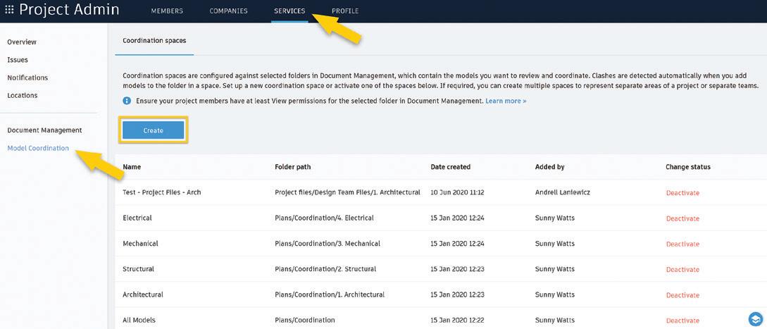
Figure 5
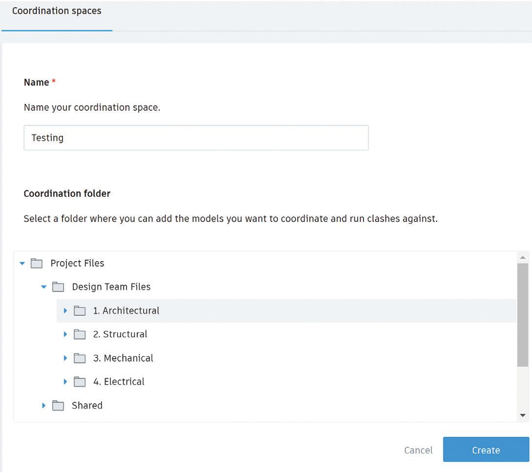
Once you hit “Create”, the Coordination Space will need to be named and the folder location of the models chosen. Note: the folder must already exist, but models can be added or removed later especially depending on your workflow. You will be able to cycle through all Active Coordination Spaces from within the Module.
Figure 6
And now we wait. Wait time is dependent on number of models, size of models, number of clashes, and complexity of clashes.
MODEL COORDINATION: ACTIVE CLASHES
Once you have set up your Coordination Spaces, we finally get to go into the Model Coordination Module. The Landing Page will
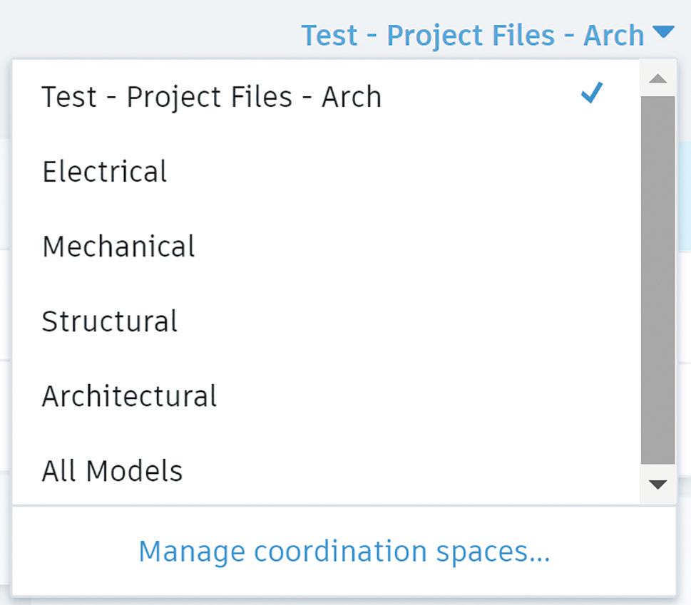
be on the Models tab. This is where all models in the Coordination Space will be listed. To cycle through the Coordination Spaces, use the drop down in the upper right.
Figure 7

Figure 8 Migrate over to the Clashes tab and the Active subtab. Here is an example of a grid matrix. Each intersection will have the number of clashes between those two models. A color intensity is applied to visually represent areas of ‘higher and lower numbers of clashes’. Darker shades indicate a higher count of clashes while lighter shades indicate fewer clashes. The key here is to note that the models in the column on the left-hand side are Primary Models. Primary Models control the number of clashes and grouping. This includes the Clash IDs. The behind-the-scenes IDs allow modelers to remove an element, re-add it, and for Model Coordination to still tie that ‘new’ element to an existing Clash Group instead of creating a New Clash – as would happen in Navisworks or Glue. This is starting to show off the power of what Model Coordination is!
To further add to some of the complexity of what is shown, you can have a different ‘total’ number of “clash groups” as compared to the number of clashes between models added up. To get a clearer understanding, let’s discuss managing these clashes and how the API is working!
Selecting an intersecting box will open the Model Coordination Viewer with those two models and those clashes only. If you select a row by clicking on the model on the left-hand side, it will open all of the models and display all of the clashes with that model.
MANAGING CLASHES
The Viewer in Model Coordination is the same Viewer across all of BIM 360. It does have one notable difference: Levels is on the bottom toolbar and not the side fly-out menu. It opens a list of the levels and will isolate the view to just that level. Counterintuitively, in order to restore the model to the full view and not a section around the level, you must select the level again. Essentially, the level names in the dialog box function as Toggles.
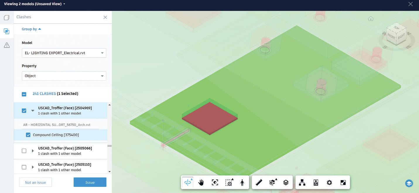
When the Viewer opens, you will see green and red geometry: red being the Grouped By Model’s geometries and green being the model geometry that is clashing with it. These colors will be a bit muted and the rest of the model will be either ghosted out or not visible based on your options set. On the left-hand side, the Clashes fly-out menu will be open. At the top will be the main “Model” to group by – you can switch this, and the colors will swap as will the groupings. However, it will not change which model is primary and what the clash IDs assigned to those geometries are. Note: a clash can come up multiple times this way as the IDs are based on the primary models, not the groups.
The next item is “Property”. When Autodesk reimagined Clash Detection, they focused on the main properties that were used to create clash sets and why. It boiled down to Object (geometry specific with no sets needed), System Name (for MEP), and Type Name (for more specific geometry grouping across multiple trades.). As you cycle through these options, you will notice the clash groups change, but not the number of Clashes. This should help clarify why the
numbers of Clash Groups and individual clashes have different numbers on the Clash Matrix.
Once you have set up how you want your clash groups set – for now – select a clash. When you do, that clash will brighten, the others will become transparent and even more faded. If you use the drop down, you will see all geometries involved in the clash (if there is more than one). The ability to select the entire Clash Group or individual parts of the clash gives you more control. Select the items and then choose if they are an “Issue” or “Not an issue”. See figure 9.
Figure 10
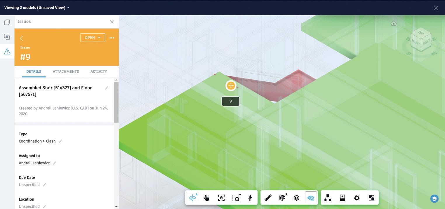
If you choose Issue: click to place a point on the red geometry, fill in the Issue (some will automatically fill in for you), and click “Create”.
If you choose Not an issue: choose a reason, fill in comments (if needed), and click “OK”.
Remember how the Levels dialog was previously pointed out and ultimately raises the question of why would that even be useful as opposed to a section box? Another powerful feature of Model Coordination that Navisworks does not have, is the ability for you to select a geometry in the viewer and have it pull up that clash!
LET’S TALK WORKFLOWS
Did you catch that? The Issues get assigned to the red geometry. You can also group by System Name or Type Name. Using these options, you can quickly get through a majority of typical “Not an issue” clashes. You can even have multiple Clashes and Clash Groups selected at once.
For example: Sheet metal and Architectural models are being clashed; set the red model to the sheet metal and change the property to Type Name, scroll through the Clash Groups to “Flex” (typically Flex – Round), select all, review to verify, and mark all as “Not an issue”. You can then repeat this with the Supply and Return Grills that intersect ceilings. Apply this to a clash between Architectural and Lighting: group by Architectural Model and Type Name to review clash groups with the ceiling. Uncheck items that are “actually issues” and mark the remaining clashes in the Clash Group(s) as “Not an issue”.
Issues function as Issues. You can use the Activity area and tag others that might need to be involved, you can reference other drawings or attachments, manage the Issues by Due Dates, get a report of the counts in the Home Module, and more. Issues have Custom Attributes! This means you can set an Attribute for Priority, add it to Coordination and Clash Issue Types, and then sort and manage the Clash Issues by Priority. All Issues are tracked, so you can view when someone reviewed a Clash Issue. This helps a coordination team change the conversation to accountability and teamwork instead of trying to place blame or play Hot Potato.
There is currently an add-in to tie BIM 360 Issues into Navisworks Manage, but only in NWD files. This creates an interesting workflow of being able to view Model Issues in Navisworks and even create them, but to not have a living model or have Navisworks Clashes translate to Issues in BIM 360. The good news is that Autodesk has added more communication between Model Coordination and Navisworks on their roadmap in the upcoming months. The workflows should change with new possibilities opening up. So, stay informed!
FORGE APPLIED PROGRAMING INTERFACE (API)
To understand a bit more of how Model Coordination works, here is a basic diagram from the Model Coordination API page from Autodesk. It illustrates what clashes feed the clash numbers versus the clash groups.
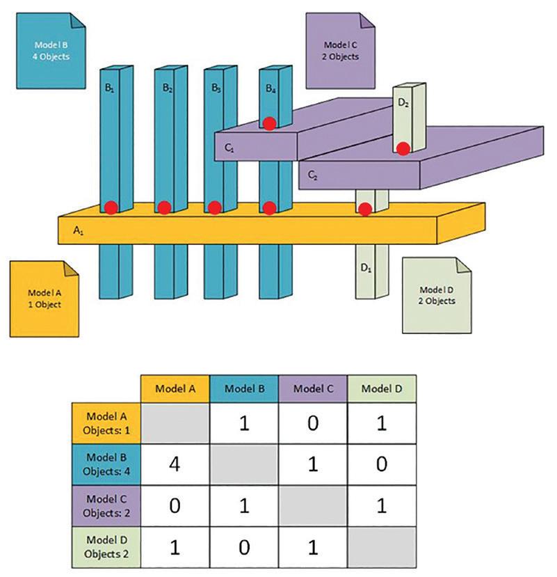
Figure 11
Autodesk has exposed some of the Forge API (currently in Beta) for Model Coordination. With what has been exposed, it increases the ability to manage clashes such as adding newly closed Clash Groups to a Closed clash that was already created. The API will allow you to automate the examples from above. You will
potentially be able to take an item with “Flex” in its property and assign it to a closed group. The API does expose more options in Model Coordination than the interface gives you direct access to. However, Revit uses C#, and Forge uses JavaScript, Python, and more. So, your current developer(s) may need some additional training to get this up and running.
RELATES TO NAVISWORKS
Navisworks Manage is a Navisworks Working file, or NWF, while in BIM 360, there are Coordination Spaces. In Navisworks, there is the tool Clash Detective. In BIM 360, there is the module Model Coordination. Within Clash Detective, there are Clash Tests. Within Model Coordination, there are Rows and Cells that are referred to as Clash Tests – automatically set up from the Coordination Space. Once clashes are run, Navisworks must be manually told to update and Model Coordination will automatically do it when opened. In a Clash Test, clashes come in as New while existing ones become Active once the Clash Test is updated. In Coordination Spaces, all Clashes that are unassigned and open are Active. When reviewing clashes in Navisworks, they can be marked as ‘Reviewed’, ‘Approved’, or ‘Resolved’. In Model Coordination, reviewed clashes get marked as ‘Assigned’ once they are made into an “Issue”; or ‘Closed’ once they are marked as “Not an issue”. This makes the process of managing clashes very cut and dry with assigning responsibility for a clash. In Navisworks, a Clash Report can be generated with several options and multiple deliverable file types. In Model Coordination, Issues would be filtered to Clash/Coordination and exported. Since file versions serve as records of submissions to track changes, there are no other main goals behind this reimagined process than tracking and resolving clashes.
CHALLENGES
Several challenges exist to Model Coordination. When you mark a clash as an Issue, the Issue that pops up to fill out does not have all the fields available. You have to Assign the Issue, then go into it through either the Assigned sub-tab or through Issues in Document Management to fill in more information. Information such as any Custom Attributes like Priority, add another person who needs to look at it, or change the Assigned To field from a specific person to a Company. Another complication to Model Coordination is with the switching of models. While you can click a geometry in the Viewer, and it will load the clash, if a clash is selected and you switch the Model to group by, the clash nor the geometries are still selected. Since an Issue only attaches to the red geometry, if the other model is the one that holds the geometry that needs to be moved or have the Issue associated with it, you cannot simply select the geometry, swap the models, and make an Issue from the new Clash Group.
With Issues, the challenges are focused around core functionality. In the linked file, the other model causing the clash does not appear, nor is it in the reference documents. This means that only the red model that the Issue is associated with gets loaded. If a pipe is intersecting a duct and the pipe was what was tagged, then the piping model loads. The specific pipe is even highlighted, but there is no information about where it is hitting the duct or where it would need to move to resolve the clash. Since Model Coordination is one of the few viewers where all models can be aggregated, this can be a challenge to track down. To solve this, use the element ID, find it in the Revit model and have an NWC or linked Revit file of the duct loaded, and that will give you a complete picture.
Since Sets are not a true thing in Model Coordination, a lot of specifics and existing workflows must be evaluated and either tossed out entirely or replaced. This is by no means an exhaustive list of challenges but are the main items to keep in mind for developing workflows for Model Coordination.
Autodesk does keep coming out with new features, enhancements, and connections. These challenges could be a thing of the past with one update.
CONCLUSION
Model Coordination is fast! It tracks Assigned Clashes and creates accountability, changing the conversation from “I” to “we”. With some of the current challenges it faces, General Contractors and Fabrication Modelers are less likely to see adoption and success easily. However, it is so user friendly and intuitive that this is what I would recommend for Designers, Architects, MEP, and anyone else. Use the high level of Clash Detection this gives to further your design files before turning them over for Fabrication. I would even advocate for this to be used for initial coordination while the GC is waiting for Fabrication Models to be produced. This will highlight areas of concern early, and it shows an aggregated model with an easy-to-use interface to review with the Project team or even owners. It can put you weeks ahead in the coordination process in that way. Model Coordination is a solid tool that is poised to only get better.
Andrell Laniewicz has working in the VDC world since 2011. During this time, she has been involved in everything from Model Coordination, 4D, 5D, and Quantification to Proposals, Site Logistics, and more. She has worked for General Contractors and MEP Design to Fabrication firms. She has taught BIM for Construction Management at Universities, presented at Autodesk University and BiLT, and consistently delivers social media content. At U.S. CAD, Andrell works with clients to evaluate their existing workflows, implement soltuions and technology, and providing training to get clients to their ultimate end goal. She focuses on Revit, Navisworks, BIM 360, FormIt, and MSuite within Architecture, Construction, and Fabrication. She has her Certificate of Management in Building Information Modeling from AGC of DC.


