
12 minute read
Civil 3D and Revit Civil 3D and Revit Coordination

from AUGIWorld
by AUGI, Inc.

Civil 3D And Revit Coordination
A little change in Revit causes a potential headache for Civil and the Revit users unless you change one setting…
Editor's Note: The following article features some active links, in order to access the linked articles please read the online or pdf version of AUGIWorld. ➲ R evit and Civil 3D! Why can’t we just all get along!!! • what settings need to be set in civil 3d? • What is the best method? the most consistant method? A NEW ISSUE ARISES MAKING IT MORE It is amazing to see that these two programs still cause so much frustration, headaches and contentious relations between Civil/Survey and everyone else. Almost a decade or so ago, I had an established method for positioning and coordinating both Revit and Civil 3D files work together. I even made my first video about this very topic, and sadly not much has changed. COMPLICATED. While teaching a class in the 2020 versions I noticed certain objects would rotate to another location on certain projects, but not all. At first, I just chucked it up as I fat fingered it, but upon further investigation I found the problem to be much more serious. Currently no one seems to be aware of this issue! Aside from a couple of coordinate changes under Revit’s hood, and an underutilized tool put out by Autodesk in 2015 called the Shared Reference Point Tool, it all remains the same. So why is this very topic STILL one of the top searches in our industry? • Why are there over 3,000 classes on Autodesk University covering this topic? • Why does this topic still confuse people? • How can you get consistent results? • Is there a Civil Site Template in Revit? • what seetings need to be on or off in revit? The issue is that any AutoCAD 3D objects, like a solid, or a Civil 3D Surface, would appear to rotate away from the rest of the AutoCAD 2D objects, and they were in the SAME FILE! See figure 1 for example.
After talking to various Revit experts and getting their various ways of coordination, being forwarded Autodesk University links, blogs, websites and YouTube videos, I ended up more confused than ever! Even Autodesk’s official Help files weren’t helpful. They had a
Civil 3D and Revit PRODUCT FOCUS
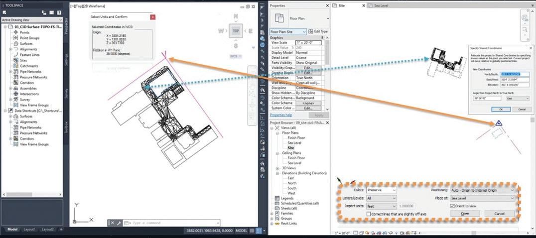
Figure 1
“Best Practices” one and it left out the “Best Practice” or actual workflow.
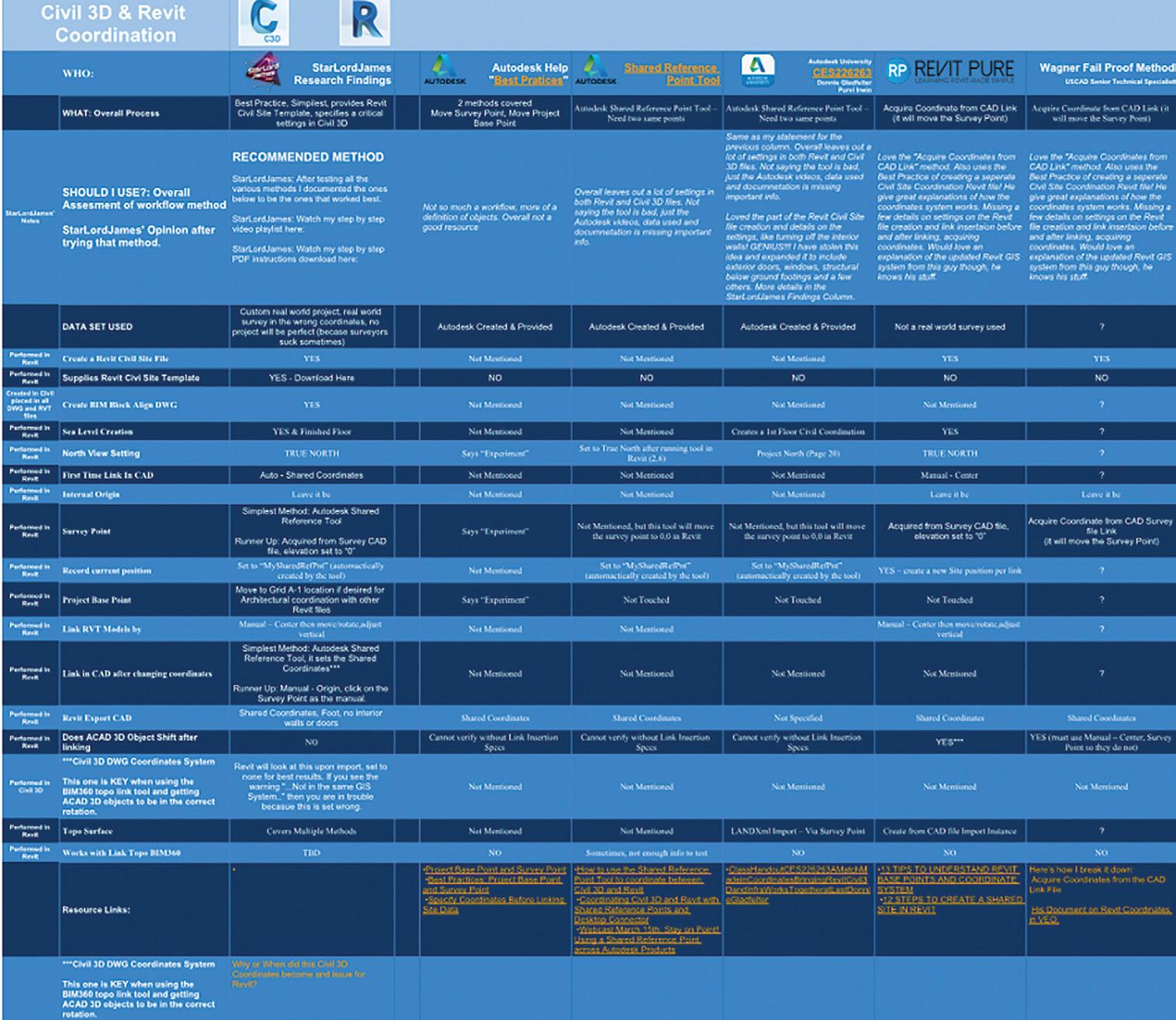
While cataloging the various ways trying to find some commonality, I also noticed that all the Autodesk and Autodesk University data sets were all the exact same one (figure 2). This made me a little suspicious to say the least. If you want to see the spreadsheet of my findings go to https://docs.google.com/ spreadsheets/d/1yPGpiPRdjGApf6QaQ1UgbkO68HUm5KrW2f1uzg1OfM/ edit?usp=sharing
There were lots of holes in the AU classes, and by holes I mean missing steps.
Like what insertion method did they use to link in Revit and CAD files? Did they start with Auto - Center? Did they change the view range in Revit to see the data? Did they set the view to Project North or True North? Will that affect the insertion while linking? Did they create a new “Position”? Figure 2 Did they just use the Autodesk Shared Reference Point tool? What other settings did they use in their Revit template before they started? What settings have been done to the Civil 3D DWG?
AUTODESK AND A BIGGER WRENCH
Now to throw an even bigger wrench into the coordination. When I performed any of the processes in the spreadsheet mentioned above, all of them were missing important settings. They all assume your templates are the same.
PRODUCT FOCUS Civil 3D and Revit

Figure 3
No matter which process I used, NONE of them would place the Linked Topography in BIM360 to the correct location for this project (figure 3).
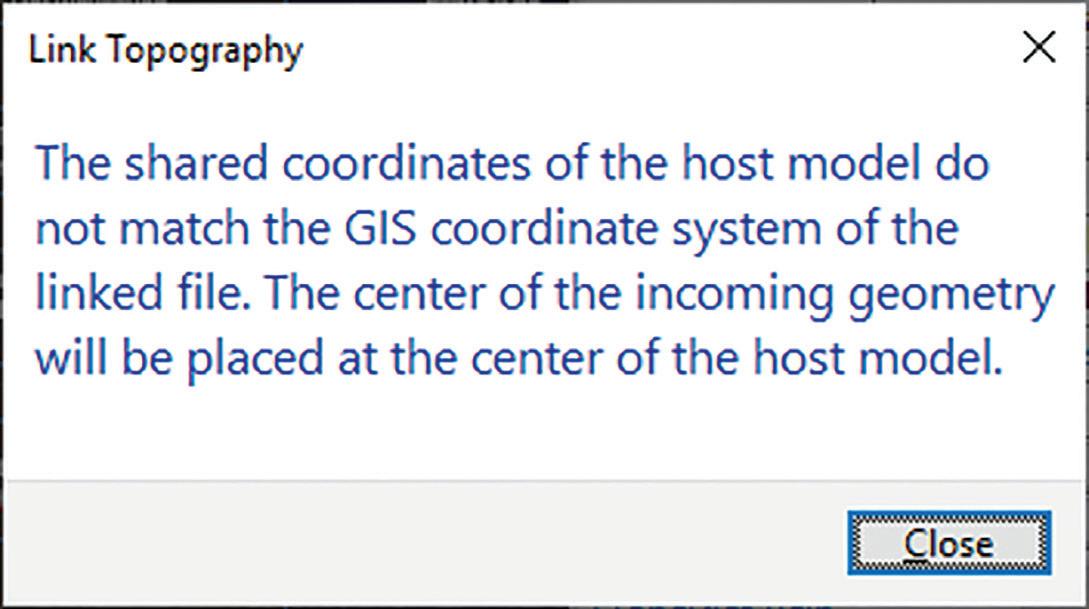
Not to mention all the error dialogs I would get… If you ever see a dialog box in Revit like the one in fugure 4 this means your coordinate system is not working or setup correctly. This will cause your file to default to Auto – Center – Center.
THE EUREKA MOMENT AND THE FIX!
After banging my head on the desk (not really) and three days into failed attempts, reading more than I do in an entire average year, and watching hours of videos I finally figured it out! And guess what? None of that reading, watching and trying told me the key. But the sayings are true, persistence is key, and in the words of Thomas Edison:
“I have not failed. I’ve just found 10,000 ways that won’t work.” It all has to do with the way Revit handles files with GIS Coordinates now. (My suspicion is that this change was to even further enhance the Autodesk & Esri relationship. Hopefully provide an ArcGIS import option inside Revit. I know they could greatly benefit from the free public GIS data out there and would
make them setup the Revit file in the right coordinate system to begin with.)
My theory on the change in Revit that caused the issue came from info provided by one of my go to Revit gurus:
“Revit 2020.2 (note the .2) changed the Project Base Point a little bit. They took away the clip, which means that the coordinates will change as you move it vs not changing when it was clipped before. Some people relied on changing the Project Base Point this way. The Survey Point continues to work the same.” - Doug Bowers
Now that you have read all the way down to here, or at least skimmed to find the fix. Here it is. It is just ONE little, but big setting in Civil 3D that must be changed. The key term that jumped out at me was in the Revit error dialog box: The share
coordinates of the host model do not match the GIS coordinate system of the linked file…
Ironically when you watch all the Autodesk videos, and the Autodesk University handouts, they all say to just ignore this box. I was like, when did Revit understand GIS Coordinate systems? And then it hit me in the face like a ton of bricks, ‘no match to Civil
Figure 4: You do not want to see this box; it means you are about to get Auto – Center – Center
3D files GIS coordinate system’, is it really that simple?
Figure 5
I fired up Civil 3D, went to Toolspace > Settings > Drawing Settings > Units and Coordinates > changed it to No datum, no projection. Then I published the surface again and saved the file,
Civil 3D and Revit PRODUCT FOCUS

Figure 6 waited for BIM360 to update. In Revit I tried linking the surface again and EUREKA! That was it! The surface landed in the correct spot on the horizontal.
Then I found out the vertical was off!
Here we go again, but since I have already spent 22 hours trying various experiments, I knew there could only be a few small settings that could be the culprit. The BIM 360 Linked Topography was dropping down to a “0” elevation (figure 6). I tried to just move the Linked Topo.
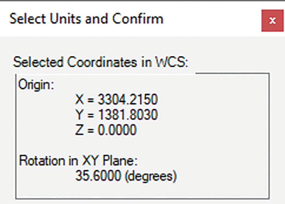
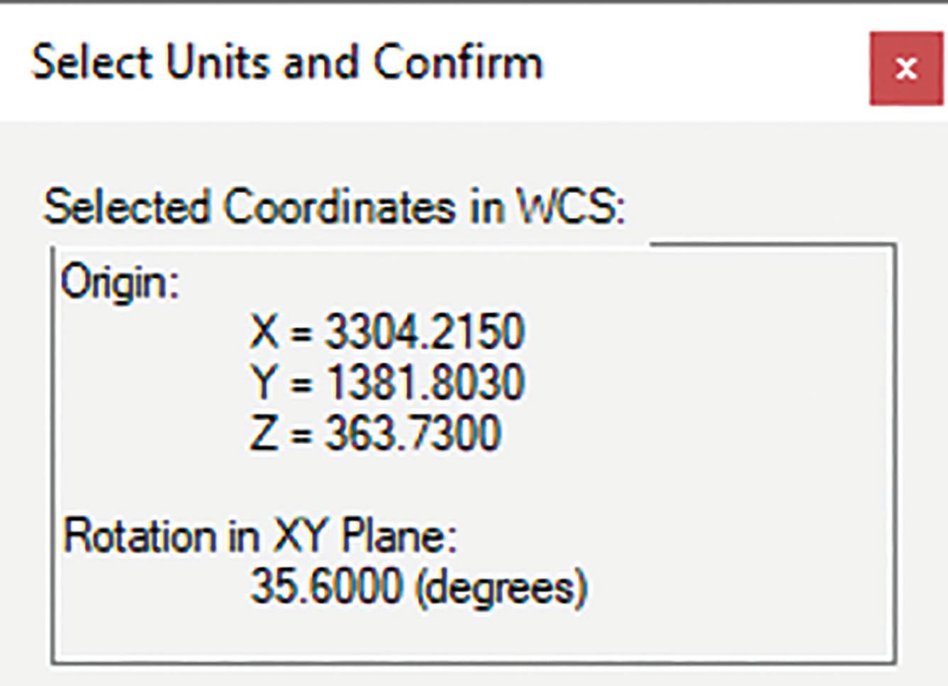
I remembered I had used an elevated line to run the Shared Reference Point Tool. So that line got flattened and I started the entire process again. This time the surface came in correctly. Make sure the line you use for the Shared Reference Point Tool is at elevation “0” (figures 7 & 8). Note this is only necessary when using the BIM360 Link Topography option.
It appears that BIM360 is extremely picky, uses the Survey point (and Site Position) as the “0,0,0”. I don’t know why it doesn’t like it when you have an elevation specified.
WHY DOES THIS HAPPEN
Well this opens a very sore wound between Civil Engineers and Surveyors. Not all surveyors take the time, or don’t know who to place their survey in an actual coordinate system.
PRODUCT FOCUS Civil 3D and Revit
Figure 9
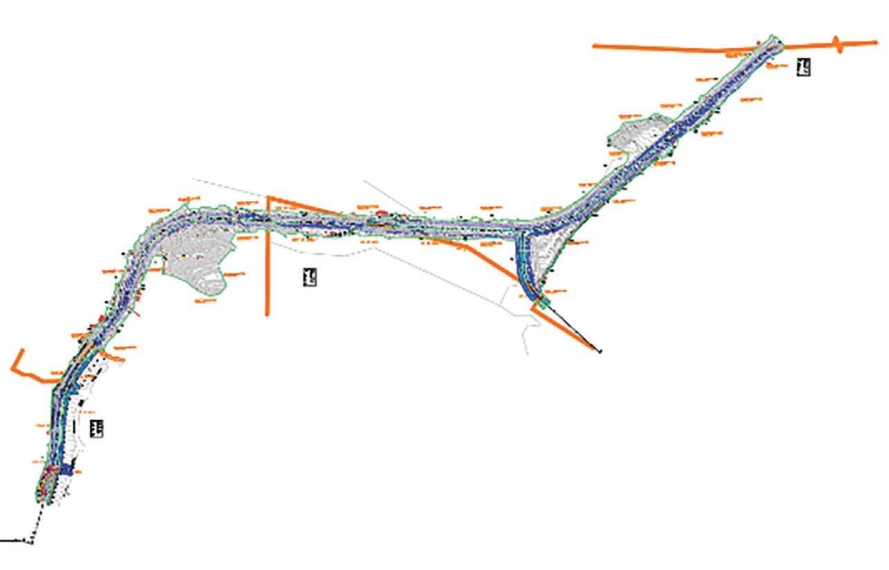
Figure 10 It is common practice for surveyors to perform what is traditionally referred to as a ‘here survey’. This survey is tied to a local benchmark, etc. Not an actual datum or coordinate linked into a “known coordinate” system that can be used in an GIS capable program.
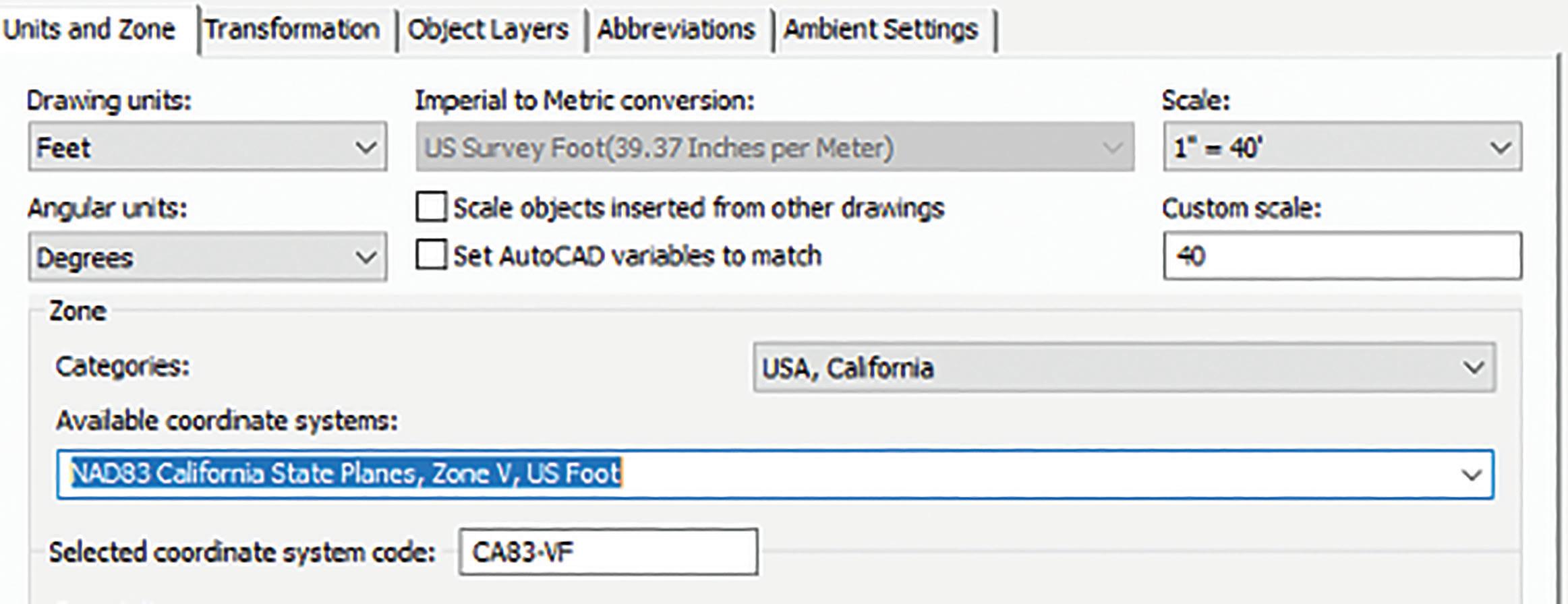
Tips on how to check if your survey is in a known GIS Coordinate system: 1. Open the Survey in Civil 3D 2. Toolspace > Settings > Drawing Settings > Units and Coordinates > change the coordinate system to the state planes for the area of the project, those are the most commonly used. (Also note Revit does not understand International Feet). See figure 9. 3. The GEOLOCATION context ribbon should pop up, on the Online Maps panel > Map Off, change to
Maps Aerial or any of the others. 4. If the background maps lineup then you have a winner!
This Surveyor is a keeper! They provided everything, points, alignments, surfaces. With the world of easy access to GIS this will help you leverage that useful data. It also means it will line up inside of InfraWorks without a fuss.
Here are a few keyS TO tell if your survey is bad: • Your survey cannot be placed on your project in a known coordinate system.
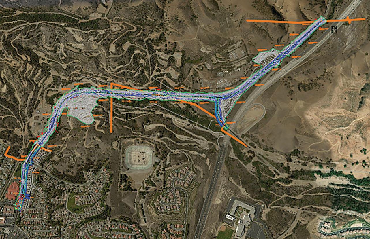
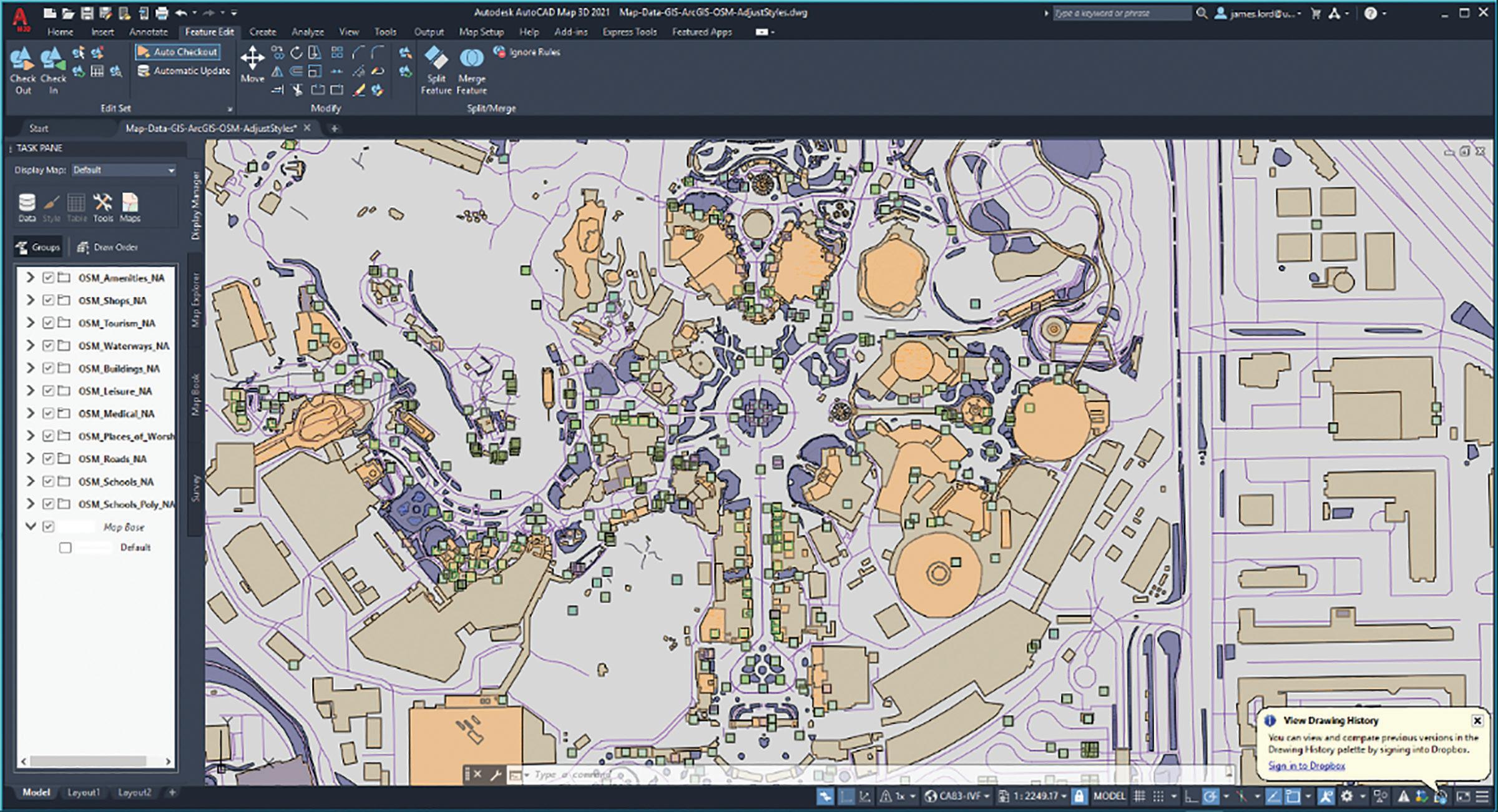
Every project needs some form of a survey to document the existing conditions. The survey sets the foundation for the rest of the project. If the foundation is in the wrong location, how good do you think your data will be? You will not be able to tie in ANY GIS data, and there is a whole new world out there. See the images below of some GIS data that was free and easy to import into Map 3D, Civil 3D, or InfraWorks. My next article will go into more detail about this new world of data at your fingertips!
Figure 12
Figure 13
Civil 3D and Revit PRODUCT FOCUS

NOW TO ANSWER THE REMAINING QUESTIONS
How can you get consistent results?
Follow this guide here, but ultimately it depends on what data you want and what you would like to use it for. THE KEY IS ALWAYS TO ESTABLISH A SHARED COORDINATE AT THE START OF THE PROJECT!
Is there a Civil Site Template in Revit? what seTtings need to be on or off in revit?
• YES! I have created a Revit Site Plan file with a lot of setting that are specific to a Civil site file.
If you would like a copy of this, please take our
Revit and Civil 3D class.
What settings need to be set in civil 3d?
• Make sure that your dwg’s do not have a coordinate system set unless they are in a known coordinate system.
Figure 14
What is the best method? the most consistant method?
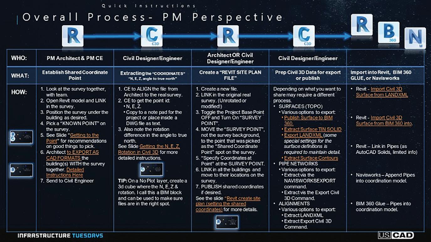
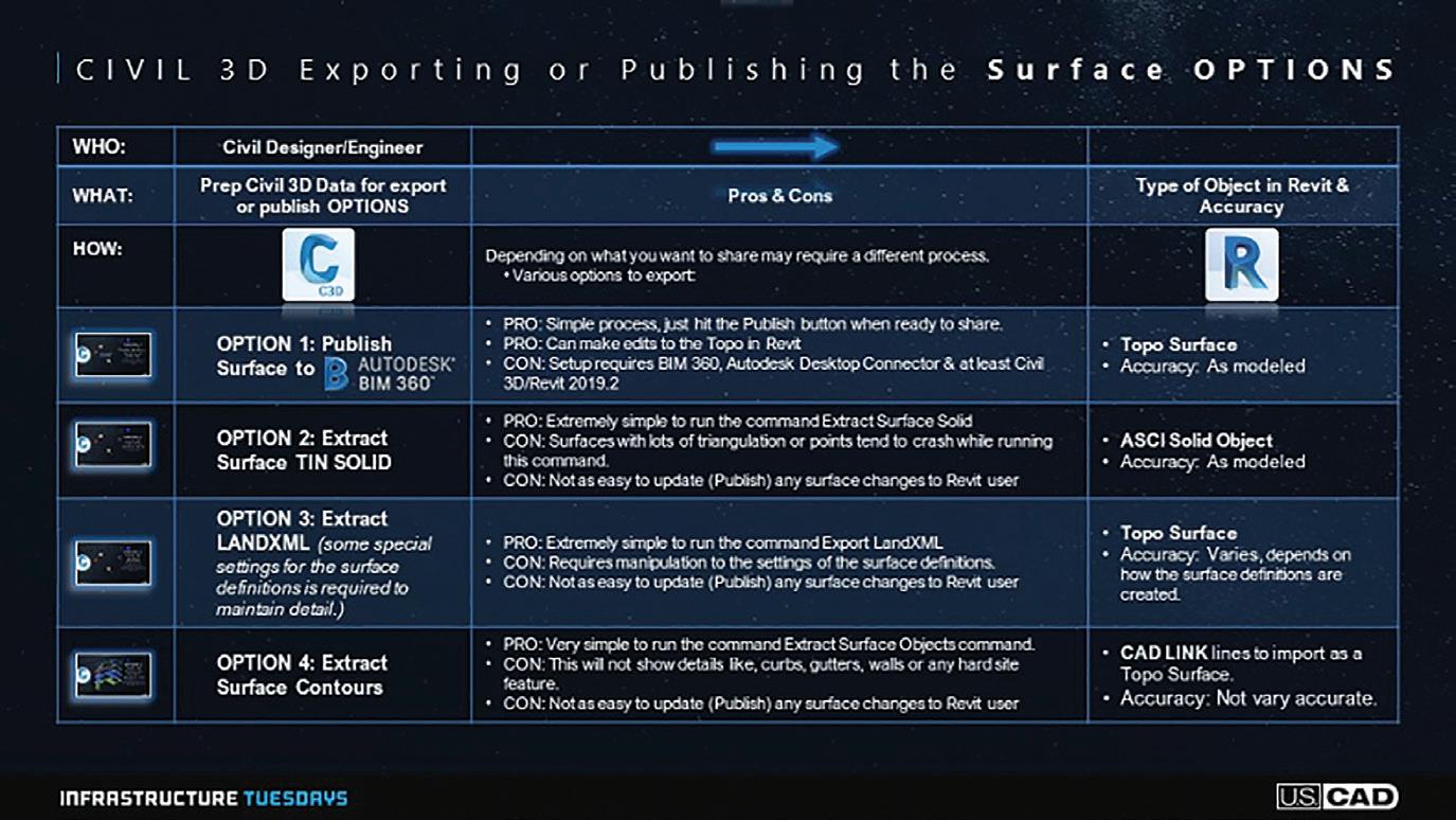
RECOMMENDED WORKFLOW
Here is a quick outline, but use the links and documents provided below for more details. • Get a good survey, in a known coordinate system. • Establish the point on that survey you will use as soon as possible. (If you can’t get a survey that quick, then use the free GIS parcel data in Figure 15 your area!) • Use the Shared Reference Point Tool, it will make your life a lot easier! • Use my Civil Site Revit Template (To see what settings I have changed in that template click here) • Follow the Instructions: • Watch out for My Video Playlist to be posted on my YouTube here and I will also post a link to the playlist on my LinkedIn:
https://www.linkedin.com/in/starlordjames/ My PDF Handout here
NOW YOU ARE SETUP FOR SUCCESS
If you follow the info above, you will not have any headaches, well unless program changes happen again.
James Lord is 100% nerd at heart. I love all new technology, software and any futurist view I can get my hands on. I enjoy learning about new features or deciphering the inner-workings and I especially love discovering new uses for things not originally intended. Creating new workflows to increase efficiency is always my goal in whatever I do. “Why do something the hard way or waste time just because that is the way we have always done it?” I love traveling, meeting new people and just listening to their stories, issues or concerns. It really doesn't matter if it is a personal or a technical issue, the joy comes from trying to figure out a solution to that issue, or just letting someone vent. Being helpful in any way is a truly rewarding experience. As a presenter, teacher, instructor and mentor, I am always trying to find a better and more entertaining way to effectively communicate with people. We all learn and process information differently, so I try to adapt on the fly when I can tell someone is just not getting it. If you can make it fun, then they are more likely to remember. Sometimes the content can be a bit dense, so it is entertaining to play a game or put a spin on it, like when I was tasked to create an instructional video about using a plotter. I threw in a little Star Wars to spice it up: https://www.youtube.com/watch?v=VumIGDDYwzc . Checkout more of my published articles via my LinkedIn page: https://www.linkedin.com/in/starlordjames
AUGI MEMBER Members Reach Higher with Expanded Benefits MEMBER MEMBER
AUGI is introducing three new Membership levels that will bring you more benefits than ever before.
Each level will bring you more content and expertise to share with fellow members, plus provide an expanded, more interactive website, publication access, and much more!

MEMBER MEMBER MEMBER
Basic members have access to: •Forums •HotNews (last 12 months) •AUGIWorld (last 12 months)
DUES: Free
MEMBER Premier members have access to: • Forums • HotNews (last 24 months) • AUGIWorld (last 24 months)
DUES: $25
MEMBER Professional members have access to: • Forums • HotNews (full access) • AUGIWorld (full access and in print) • ADN 2013 Standard
Membership Offer DUES: $100


