16 minute read
Cutting Carbon Emissions and Costs in Pumping Stations


Cutting Carbon Emissions and Costs in Pumping Stations
By: T-T Pumps Limited
In 2021 the UK Environment Agency (EA) pledged to reach net zero by 2030. The document states that the 360 pumping stations the EA operates across the UK produces 17,000 tonnes of carbon emissions annually, which they aim to reduce by 45%.
To achieve this, the EA has set out plans to upgrade all pumps to operate on greener fuel options and to generate and utilise renewable energy. If successful, the EA will reduce their pumping station carbon emissions by 7650 tonnes a year. This is a great step towards tackling the environmental effects of pumping stations, but large-scale pump upgrades and converting to new fuel options is not always feasible for operators of domestic, private, commercial and industrial stations.
So how can you get involved?
An economical way of reducing your pumping station’s environmental impact is to implement efficient controls and monitoring processes. This will not only streamline your energy usage, but also extend the life of your pumping station and benefit your bottom line.
Controls
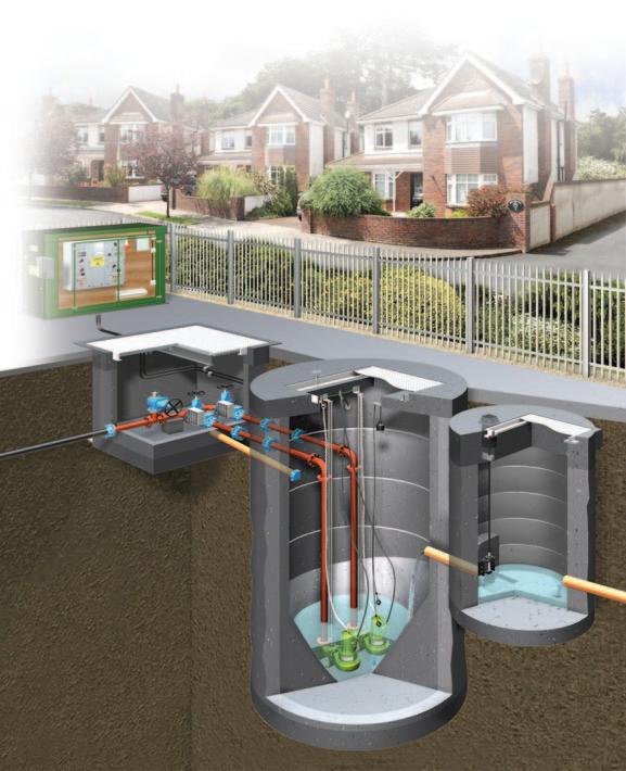
The most common forms of pumping station control are wet well level and pump speed control systems.
For level control float switches are the most versatile and budget friendly solution. They are installed in pumping station wet wells to monitor fluid levels and come in two designs –digital floats detect when liquid reaches a pre-set point in the well, whereas analogue floats provide real-time readings of wet well levels.
Pump speed can be controlled by Variable Speed Drives (VSDs) – VSDs control the speed of a pump’s electric motor by adjusting the frequency and voltage of the electrical input that is provided.
Pump efficiency: In applications with variable flow rates, such as sewage management, pumping stations require multiple pumps to ensure that enough water can be transferred from the wet well in the case of a surge. Continuously running multiple pumps in anticipation of a spike in demand wastes energy and money, as low wet well levels will not require all pumps to be operating.
Digital float switches can save energy by switching pumps on and off to reflect the level of fluid in a wet well – only powering the pumps that are needed to reliably prevent an overflow. This is the most economical way of reducing pumping station carbon emissions and simultaneously cuts energy expenditure.
For complete pump efficiency, analogue float switches can be paired with Variable Speed Drives (VSDs).
When paired with an analogue float switch VSDs can control pump speed to match current wet well levels, using a more precise amount of energy in comparison to digital float switches that turn pumps on and off to manage discharge rates. This method of cutting energy usage is initially more expensive to install, but will save more money overtime as energy is used more accurately.
Increased life, reduced maintenance: Float switches will protect pumps from dry running by switching them off when wet well levels are low. If pumps continue to operate with little to no liquid available motors can overheat and cavitation can occur, causing damage to impellers. Switching pumps off when fluid levels are low reduces equipment wear and potential damage to your system.
Similarly, VSDs can respond to changes in system variables such as motor temperature, water supply levels, and overall system pressure. By responding to these changing factors VSDs reduce the risk of overheated motors, dry-running pumps and pipe leaks, ultimately minimising wear and tear on pumping components.
Both of these methods will increase the lifespan of your pumping station, cutting its overall carbon emissions and running costs as the frequency of maintenance and repairs is reduced.
Monitoring
An effective monitoring system can reduce the overall carbon emissions of a pumping station through data logging. Storing operational data allows you to form an image of a pumping station’s regular operating parameters. With this, changes in incoming data – which may signal an oncoming failure or breakdown – can be identified and dealt with proactively.
Early intervention in response to changes in monitoring data can solve an issue before it develops into a full breakdown, reducing the number of callouts and parts needed to repair the pumping station, saving on carbon emissions related to travel and manufacturing.
Proactive maintenance also protects the environment, dealing with issues before they lead to a breakdown ensures no leaking pipes or overflowing wet wells can pollute the surrounding wildlife.
Conclusion
These smaller-scale changes may not live up to the carbon cutting expectations of the EA’s plan to reach net zero by 2030, but they will extend equipment life and streamline pump power consumption, ultimately lowering the overall carbon emissions and costs of operating and maintaining a pumping station for the benefit of the environment. ■
For more information, Email: response@ttpumps.com Phone: +44 (0) 1630 647200
Greene Tweed Composite Pump Solutions
For more than 150 years, Greene Tweed’s customers have relied on the company’s materials expertise and collaborative approach to the design and manufacture of elastomeric, thermoplastic, and thermoplastic composite solutions, which deliver proven performance in extreme and demanding operating environments.
A global company with facilities across North America, Europe, and Asia, Greene Tweed serves customers throughout a diverse range of markets, including energy, aerospace, defence, industrial, life sciences, and semiconductor.

WR® materials family
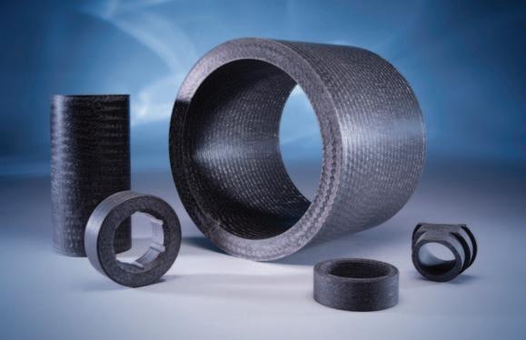
Greene Tweed’s WR® (Wear Resistant) line offers excellent wear and friction properties, along with superior non-galling and non-seizing performance. The WR® material portfolio enables extended MTBR and improved reliability. Offering extended dry-run performance and exceptional chemical resistance, our WR® materials can often reduce running clearances by more than 50 percent. A reduced clearance means better system efficiency and increased shaft stability through vibration reduction.
AR® materials family
Many traditional wear parts in pumps require frequent replacement due to the abrasive environments in which they operate. Expensive component repair and replacement is required in such cases. Greene Tweed has engineered a pair of Abrasion-Resistant (AR®) composite material offerings that help increase your intervals between overhauls and improve pump reliability.
Greene Tweed’s pump components are engineered from our high-performance thermoplastic composite materials for centrifugal pumps and magnetic drive pumps. End-users throughout the world specify our products for their refineries, petrochemical plants, and power generation plants.
Customers who upgrade to composite wear parts from metal wear parts in their pumps experience reliability improvements and report:
• Improved MTBR and routine maintenance tasks
• Minimized chance of catastrophic damage
• Reduced vibration
• Improved reliability and efficiency of older equipment
• Reduced total cost of ownership for the equipment
Composite Benefits
Increased efficiency – The reduced clearance of the composite material versus the metallic hardware improves pump performance and efficiency.
Dry-run protection – The non-galling and non-seizing properties of composites help avoid catastrophic pump failures caused by dry-run startup or excessive vibration. End-users throughout the world specify our products for their refineries, petrochemical plants, and power generation plants.
Greene Tweed’s line of high-performance thermoplastics composites offers wear and abrasion resistance in a variety of materials, temperature ranges, and operating pressures to meet different applications. ■


PFAS restriction and sealing devices
By: Mike Eason, Mark Neal and Ralf Vogel
On 07.02.23 ECHA (European Chemicals Agency) issued the PFAS Restriction Proposal. The ECHA committees will begin their scientific evaluation of the proposal and the six-month public consultation started on 22.03.23. How will this proposal effect the sealing industry, end users and producers of PFAS?
Sealing Devices are engineered products specifically designed to prevent gases or liquids escaping to atmosphere. They are used in processes which deliver water and electricity to your home, all forms of transport from bicycles to planes, in engines, washing machines, taps, throughout chemical plants, oil refineries, power stations to food processing plants. They utilise a range of fluoropolymers which are stable at high temperatures and are largely inert to aggressive chemicals. There is no alternative to the fluoropolymers used in Sealing Devices which can cater for such environments or work as effectively to prevent the release of process fluids or gases to the environment. To ban them would grind society to a halt, planes would not fly, water would not reach your home, gas and electricity supplies would stop and cars would fail. A proposed generic ban for all PFAS products as proposed by the EU and Federal bodies in the U.S. is necessary to prevent the bio accumulation of them throughout the world but for the Sealing Devices specifically it would have a wide-ranging negative impact on society and increase the level of emissions to atmosphere that the industry has fought to reduce over the last 70 years.
Here is the reason why
The use of fluoropolymer (fluoroplastics and fluoroelastomers) in the Sealing Industry
Sealing Devices retain media (powders, gas and liquids) inside hardware (process or storage equipment). Media within nonmoving equipment are secured by “Static Seals” such as gaskets, whereas pistons and rotating equipment such as bearings and gearbox use “Dynamic Seals”. Hazardous, toxic, flammable, corrosive and reactive chemicals are media found in different industries all of which require high performance seals to be used efficiently and safely. Seals are used in aggressive environments where they can be exposed to conditions, such as, wear, abrasion, radiation, and extremes of temperature.
Different types of materials; metals, Inorganics such as ceramics and graphite, and polymers (plastics and cross-linked elastomers) are used in industrial seals. In each case the seal material is selected based on the specific application requirements.
Seal materials must:
1. Withstand the environmental conditions of the application, including, media, temperature, pressure, speed, and abrasion
2. Not damage other equipment (hardware) in which the seal is housed
3. Be compliant with the counter surface to maximize sealing efficiency
Prevention of damage to hardware such as flanges, pipes, valves, and containers necessitates that contact seals are comprised of softer materials than the hardware into which they provide the seal. This prevents physical damage to hardware such as scoring or wear. For this reason, graphite, plastics, and elastomers are favored. Demanding applications, such as the prevention of fugitive emissions in the petrochemical industry or with toxic media and with high system pressures, require sealing materials with sufficient mechanical strength to withstand the system pressure and that have extremely low permeability to the media.
Fluoropolymers (fluoroplastics and fluoroelastomers) have unique importance for demanding industrial sealing due to their mechanical properties (strength and comparative softness) combined with chemical stability, thermal stability, low permeation, and low surface energy.
Polymers (plastics and elastomers) are manufactured from monomers which react together to from the repeating unit of the polymer. Fluoropolymers are manufactured from low molecular weight PFAS monomers and in some cases using PFAS process agents. It is an important consideration that a class ban on low molecular weight PFAS is in effect also a ban on fluoropolymers (Fluoroplastics & Fluoroelastomers).
The use of low molecular weight PFAS raw materials is limited to the manufacturing locations of the fluoropolymer and fluoroelastomer. It is therefore recommended that PFAS monomers in the polymer supply chain are exempted from any PFAS ban and that different controls are considered which enable their safe and continued use.
Use of fluoroplastics
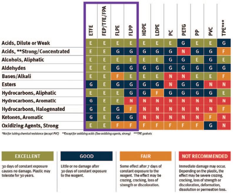
Fluoroplastics (i.e., PTFE, PFA, …) are the only plastics that combine both the broadest chemical resistance with the highest operating temperature with an acceptable compliance to counter surface and therefore are used when other alternative plastics cannot offer the require chemical & thermal resistance combination for industrial applications. Many references are available in the public domain that highlight this:
Use of fluoroelastomers
The well accepted ASTM D2000 chart below represents the elastomer families available on the market and rates them against heat and oil resistance. The green shaded area represents materials with the best chemical resistance and best thermal stability, all of which are fluorinated.
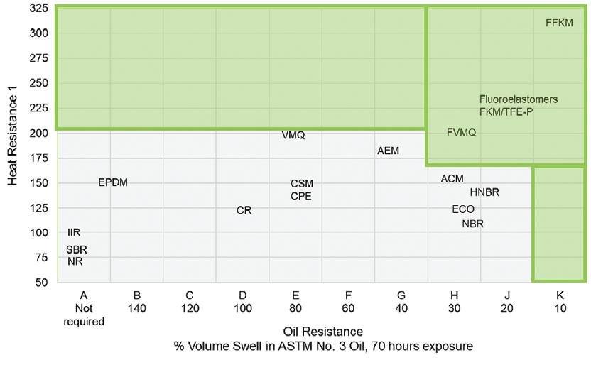
Above 200°C only fluoroelastomers come into consideration for elastomeric sealing applications and at lower temperature, the drive for using fluoroelastomer is mostly linked to the broad chemical resistance.
Per- and Polyfluoroalkyl Substances (PFAS) is a broad “Class” of materials under scrutiny for health and environmental concerns. Governments and regions are seeking to regulate the use of PFAS, which could lead to restriction in their use, stringent control measures, or a ban of this entre class of materials. REACH (Registration, Evaluation, Authorisation and Restriction of Chemicals) in the EU are seeking to restrict the use of PFAS and the placing on the market of products containing PFAS in the EU as far as possible.
1 Maximum temps at which vulcanizates can be aged for 70 hours with changes to textile strength ≤± 30%, elongation ≤ 150% and hardness ≤± 15 points fluoropolymers (fluoroplastics and fluoroelastomers) uniquely offer chemical inertness vs aggressive media with thermal stability.
Many applications are enabled in our everyday life thanks to the use of fluoropolymers:
Controversially REACH scope for proposed PFAS regulation includes both small molecules and polymers. The inclusion of small molecules in the scope for PFAS is understandable; small molecules are subject to REACH registration, they each have a unique defined chemical structure, known physical properties, and their health and environmental impact can be assessed. Small molecular weight PFAS include surfactants, plasticisers, and chemical reagents used in the manufacture of other chemicals including monomers for PFAS polymers.
By comparison, when REACH was developed, requesting registration for polymers was deemed too difficult, because of the complexity of the polymer market, in terms of the size and variability of polymers on the market. For a polymer to be of Low Concern certain criteria had to be met, including;
• High number average molecular weight of the polymer
• Negligible presence of low molecular weight materials including oligomer and residual monomer content
• Resistance of the polymer to degradation
• No functional groups in the polymer that are known to be harmful
Polymeric PFAS, also called fluoropolymers, used in the sealing industry include fluoroplastics such as PTFE which are components of gaskets and compression packings, and crosslinked fluoroelastomers (rubbers) with application as O-rings and custom geometry seals.
Fluoropolymer seals which fall within scope of PFAS are irreplaceable in certain industries and a blanket ban or regulation of these polymeric PFAS will have a profound negative impact on society (health, welfare, and standard of living). Larger molecular weight materials, such as polymers and cross-linked rubbers are non-bioavailable. PFAS polymers are considered to be Polymers of low Concern (PLC). They are critical to global development and pose no concern to public safety, yet the current REACH definition of PFAS groups these polymers together with low molecular weight PFAS of known concern such as PFOA and PFOS.
Conclusion
Linked to the high strength of the Carbon-Fluorine (C-F) bond,
• Reduction of engine emissions both for planes (Increased efficiency allowed by higher operating temperature) and cars (higher thermal resistance allowing engine downsizing)
• Production of more powerful and more energy efficient computer processors which are now part of our everyday life (Smartphone, Datacenters, Artificial Intelligence)
• Reduction in fugitive emissions linked to lower permeation from valves and flanges in industry
• Reduced worker exposure linked to longer seal lifetime in the application. Every seal changed is a potential exposure for workers to the sealed media
• Sealing of drug production vessels to allow to production of the latest disease treatment thanks to their very low to no extractable materials
Banning the use of fluoropolymers components and the use of low molecular weight PFAS intermediates at the fluoroplastic manufacturing locations would step the science of sealing backward to the 1950s timeframe.
The ESA has commissioned a specific socio-economic analysis for the sealing industry which will be forwarded to ECHA to provide evidence that PFAS fluoropolymer (Fluoroplastic & Fluoroelastomer) materials should be exempted from the proposed regulation. A more detailed position paper, including case histories, regarding PFAS can be found on the ESA website. ■
Reference Documents:
ESA Fugitive Emissions Reduction Document, https://www.esaknowledgebase.com/wp-content/uploads/2019/11/ferd_5c_v2.pdf
ESA PFAS Position Paper, https://www.europeansealing.com/wpcontent/uploads/2022/03/ESA-Position-Statement-on-proposed-PFAS-regulation-Ma rch-2022.pdf
BDI PFAS Position Paper, https://english.bdi.eu/publication/news/eu-chemicalsstrategy-restriction-of-pfas/
For more information, Phone: +33-631941600
Email: markneal@europeansealing.com
What are the regulations when fitting a macerator or lifting station?
What are the regulations when fitting a macerator or lifting station?
By: Amanda Mills of Saniflo Ltd
This article discusses building regulations when installing a macerator, pump or lifting station for any project requiring waste discharge.
Whilst macerators and lifting stations may not represent the glamorous side of the plumbing sector, they are nonetheless, some of the most useful products out there, transforming unused spaces throughout the UK.

Where conventional drainage isn’t an option, Saniflo’s extensive range enables the addition of extra facilities to buildings without disruptive and costly construction work. With solutions for black water, grey water and rain water, the options are endless:
• Changing offices into residential apartments
• Adding a washroom to a listed building
• Transforming basements (gym, swimming pool, sauna, bathroom)
• Adding a bar into a retail unit
• Underground nightclubs
• Hospital extensions
Building Regulations approval is a statutory requirement set by the Government in order to ensure that buildings are designed and constructed in accordance with regulations and associated legislation. Projects that require approval include:
• Erection of a new building
• Extension or alteration of an existing building
• Loft conversions
• Plumbing, drainage and ventilation windows, and fuel burning appliances of any type.
• Many types of electrical works on buildings.
Building Regulations are designed to protect the health and safety of building users and for projects that require a macerator, pump and/or lifting station it is mandatory to adhere to Part G and Part H. While plumbers, contractors and installers should be fully aware of the regulations, it is incumbent on the customer to ensure compliance.
Part G and Part H Building Regulations
Part G covers sanitation, hot water safety and water efficiency. And, when adding facilities and discharging to a drain, part 4.24 is the key regulation to understand;
A WC fitted with a macerator and pump may be connected to a small bore drainage system discharging to a discharge stack if:
• There is also access to a WC discharging directly to a gravity system
• The pump meets the requirements of BS EN 12050-1:2001
Part 5.10 stipulates that a sanitary appliance used for personal washing fitted with a macerator and pump may be connected to a small bore drainage system discharged to a discharge stack if:
• There is also access to washing facilities discharging directly to a gravity system

• The macerator and pump meets the requirements of BS EN 12050-2:2001
Part H covers drainage & waste disposal and the important stipulations for pumps:
2.36 Where gravity drainage is impractical, a pumping solution will be needed
2.37 This should conform to BS EN 12050 in basements and BS EN 12056-4 for pumps located inside buildings
2.38 Lifting station/pump installations for outside buildings should refer to BS EN 752 – 6 for guidance on design
2.39 where foul water is to be pumped, the effluent receiving chamber should be sized to contain a 24hr inflow to allow for disruption in service. The minimum daily discharge of foul drainage should be taken as 150 litres per head per day for domestic use. For other types of building the capacity of the receiving chamber should be based on the calculated daily demand of the water intake for the building. Where only a proportion of the foul sewage is to be pumped, then the capacity should be pro-rata. In all pumped systems the controls should be arranged to optimise operation.
Saniflo has developed a CIBSE-approved CPD programme which is designed to discuss and offer technical training on macerators and lifting stations for commercial and domestic buildings, including regulations. Appointments can be booked via marketing@saniflo.co.uk ■
For more information, Email: marketing@saniflo.co.uk Phone: +44 (0) 20 8842 0033
Pressure surge – Cause, Consequence and Mitigation
By: Tony Keville of Tomlinson Hall & Co Ltd
We have all experienced problems with pipe surge but what causes it and how do we take action to minimise the effects.
The effects of surge are destructive and can result in destruction of pumps, valves and associated pipework. But what sort of pressure do the surges reach? For that we need to look at the causes and for the purposes of this discussion lets look at one of the commonest causes.
Modern process plants use a combination of ball and butterfly valves operated in the main by pneumatic actuators. It is the time of actuation that is critical, there is a constant that needs to be calculated and that is 2L/C where L is the length of the line in metres and C is the speed of sound in the liquid. Perceived wisdom is that the minimum closing time must be greater than twice this figure. But what is the closing time defined as? If we look at ball and butterfly valves the flow does not start to be restricted until the valve is approximately 75 to 80% closed. Therefore the actual shut off time is very short and so the valve closure time must be extended to ensure the line constant is exceeded.
If we now look at the pressure that can be generated under surge conditions the Joucowsky equations can be used and a simplified version is as follows.
ΔP=ΔV*C/g
Where;-
ΔP is the surge pressure in metres
ΔV is the change in velocity in m/s
C is the speed of sound in the liquid in m/s
G is the acceleration due to gravity in m/s2- 9.81 m/s2. Using typical values of 2m/s for the liquid velocity and 1400 m/s for the speed of sound in water a typical surge pressure of 285m is achieved but to this must be added the line pack which is the head due to friction, static head and any residual pressure required for e.g. nozzles.
As can be seen this leads to very high pressures being imposed on pumps, pipes and fittings. The wave front is very steep and propagates at the speed of sound in the liquid so beats relief valves and other protection devices and can put safety devices such as bursting discs at risk of premature failure. As an example the surges that can be generated by automatic washing machines is around 700 psi as the solenoid valves close.
What steps can be taken to reduce the impact? Use slow closing valves, consider surge vessels are installed, and slow start VSDs on the motors.
Similar pressures are generated on both start up and shut off of pumps and in some instances, flywheels have to be fitted to the shafts to provide additional momentum during the rundown phase.
With the increasing use of VSDs for constant pressure systems care needs to be taken to provide signal processing to ensure that the surge spike does not prematurely trip the drive and shut it down. A delay of 500ms to a second is normally adequate to prevent this.
Sadly that is not the end of the story, When a surge is initiated and travels down a pipe run it will be reflected from ends and tee’s etc so now there are 2 wavefronts travelling in opposite directions along said pipe and then addition of the wavefronts leads to reinforcement and pressure reduction where the wavefronts coincide. It is uncanny listening to wavefront collisions in a system creating loud “bangs” in totally unexpected places.
When dealing with rigid plastic pipework the effect of surges is or can be even more destructive, the pipe can deform from a circular to a kidney shape and back again. Very rapidly leading to fatigue failure along the length of the pipe and in the case of solvent welded or fusion welded pipe, cracks will propagate through those fittings.
To present some examples the following may jog a few memories;-
• Vertical multistage pumps on boiler feed where the modulating valve closes too rapidly fail due to the seal carrier plate literally blowing out of the casting or the outer barrell becoming barrel shaped.
• End suction pumps blowing casing gaskets out of the gap.
• Mechanical seals having the rubber bellows extruded through the seat to shaft annulus.
• Peristaltic pumps blowing the tubes at the discharge side or breaking the rotor arm.
• Hygienic pumps with the clamp bands straightened out. The list is long and exhaustive.Experience has shown that it is good practice to consider the possibility of surges being present and design the possibility out at the project outset. ■


