3. RECYCLING STRATEGY SELECTION
3.1 Introduction
This chapter covers the choice of recycling strategy and recycling agent/stabilizer using the information collected during the project investigation and assumes that there is sufficient material to recycle, even if premilling is required to maintain grade height. Choosing the correct strategy is important for ensuring good long-term performance of the rehabilitated pavement. The choice of one recycling strategy or another is based on where the distresses originated and whether increased structural capacity is required as part of the rehabilitation design. A decision about which recycling agent/stabilizer to use is based on the properties of the materials that will be recycled.
A general summary of example appropriate strategies that can be used to rehabilitate different types of distresses is shown in Table 3.1.
Note that CCPR can be considered on rehabilitation projects that require vertical and/or horizontal alignment changes, given that grade changes can be readily made during milling and repaving phases of the work.
3.2 Selecting a Recycling Strategy
The decision whether to use a PDR or FDR strategy is primarily based on the origin of the distresses, and whether the goal of CAPM or rehabilitation is simply to restore structural capacity or whether the goal includes making required structural improvements and/or alignment changes. An initial decision is made based on the following steps, which are illustrated in the flowchart in Figure 3.1.
Key issues to consider include the following:
• Confirm that drainage problems can be corrected, and if not, accept that reduced performance may result. Note that poor drainage will impact the performance and life of any type of pavement regardless of how it is built, maintained or rehabilitated, and that recycled pavements are no different. Recycled pavements do not require different or “better” drainage than other CAPM or rehabilitation approaches.
UCPRC-GL-2020-01 39
Table 3.1: Example Distresses and Appropriate Recycling Strategies
a Generally appropriate if distresses are limited to top 0.2 ft (60 mm).
b Potentially more cost-effective to do PDR if distresses are deeper than 0.3 ft (90 mm).
c PDR and FDR can be done in place or using CCPR.
d If these are the only distresses on the pavement, a thin overlay, or mill and thin overlay is usually more cost-effective.
e FDR and/or CCPR with lower layer stabilization, although feasible, would typically not be cost-effective for correcting these types of surface distress.
f Only appropriate if distresses are limited to the top 0.4 ft (125 mm) or if fatigue cracks are due to debonding of upper asphalt layers within top 0.4 ft (125 mm).
g Recycling is an appropriate strategy to rehabilitate roads after drainage problems have been corrected.
• If structural improvements are not required and distresses are top-down and confined to the asphalt layers only (i.e., there are no deep ruts, no pumping of fines through the cracks, no full-depth patches or digouts, etc.), then partial-depth recycling (PDR) is an appropriate recycling strategy.
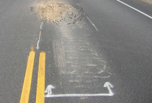
• If structural improvements are required and/or the distresses are bottom-up and affect the full depth of the asphalt layers and possibly the underlying unbound layers (i.e., deep ruts, fatigue cracking, pumping of fines through cracks, presence of full-depth patches and digouts, etc.), then either full-depth recycling (FDR) or a combination of lowerlayer/subgrade stabilization followed by placement of cold central plant recycled (CCPR) upper layers will usually be the most appropriate strategy. In some projects, a combination of PDR or FDR and thicker asphalt-surfacing may also be an option if grade changes can be accommodated.
40 UCPRC-GL-2020-01
Distress Type Example Overlay/Mill and Overlaya,b Partial-Depth Recyclingb,c Full-Depth Recyclingc CCPR Plus Lower Layer Stabilization Surface defects Raveling Yes Yesd Noe Noe Bleeding Yes Yesd Noe Noe Skid resistance Yes Yesd Noe Noe Potholes Yes Yes Noe Noe Ride quality Yes Yes Noe Noe Deformation Shoving Yes Yes Noe Noe Surface rutting Yes Yes Noe Noe Shoulder drop off No Yes Yes Noe Structural rutting No No Yes Yes Non-loadassociated cracking Oxidative Yes Yes Noe Noe Thermal Yes Yes Yes Noe Longitudinal Yes Yes Yes Yes Transverse Yes Yes Yes Yes Discontinuity No Yes Yes Yes Block No Yes Yes Yes Load-associated cracking Edge No Yesf Yes Yes Reflective No Yesf Yes Yes Fatigue No Yesf Yes Yes Base/subgrade deficiencies Sags, depressions No No Yes Yes Ride quality No Yesf Yes Yes Drainage related Weakened structure No Nog Nog Nog
Review all investigation results
Are distresses related primarily to poor drainage?
Yes
No
Are structural or alignment improvements required?
Note that poor drainage will impact the performance and life of any type of pavement, including recycled pavements
Review results from visual assessment, cores, and GPR
Are distresses top-down and only in the AC layers?
Consider drainage improvement options before proceeding with CAPM or rehabilitation design
• If the pavement requires horizontal and/or vertical alignment improvements that cannot be accommodated as part of premilling and PDR or FDR operations, then cold central plant recycling (CCPR) will usually be the most appropriate strategy, with those improvements made during the milling and CCPR material placement parts of the operation.
• If grade-height restrictions on rehabilitation projects dictate that all of the asphalt concrete, and potentially some of the underlying aggregate base, is milled off and removed from the site prior to starting recycling work, then the project should be considered as reconstruction and not as FDR. In these instances, the project should be designed following the Caltrans Highway Design Manual (HDM) procedures for reconstruction. Stabilization of
UCPRC-GL-2020-01 41
Figure 3.1: Flowchart #1: Preliminary recycling strategy decision.
Recycling Strategy Selection
Yes Yes
No No
Go to Flowchart #2 Do PDR or CCPR Do FDR, CCPR, or CCPR + lower layer/subgrade stabilization Go to Flowchart #3
any remaining materials and the subgrade should be considered and designed as stabilized base, stabilized soil, or stabilized subgrade.
If PDR (in-place or using material processed in a cold central plant) is selected, follow the steps listed in Section 3.2.1 and Flowchart #2 in Figure 3.2.
If FDR (in-place, using material processed in a cold central plant, or a combination of in-place stabilization and central plant) is selected, follow the steps in Section 3.2.2 and Flowchart #3 in Figure 3.3.
3.2.1 Partial-Depth Recycling Considerations
A number of questions should be addressed before deciding that PDR is the most appropriate choice. These are based on the findings of the project investigation and include the following:
• If the top-down distresses are limited to the top 0.2 ft (60 mm), then a mill-and-overlay or thin-overlay-only strategy may be more cost-effective than in-place recycling and should also be considered.
• If the distresses are top-down and limited to the top 0.4 ft (125 mm), then PDR is appropriate provided that:
+ Any geosynthetic materials (fabric and grids) in the asphalt concrete layers will recycle effectively, or can be removed during the recycling process before spreading and compaction.
+ RHMA-G and RHMA-O thicknesses do not exceed 25 percent of the recycle depth (gradation and compaction problems may be experienced with high recycled gap- or open-graded RHMA contents). Actions to reduce the percentage of RHMA in the recycled material (e.g., milling off the RHMA-O layer) or increase the recycle depth to reduce the percentage of RHMA can be taken if required. A decision to include higher percentages of RHMA materials in PDR layers can usually only be made after mix design testing has been completed by the contractor.
+ No large areas of large, loose blocks of distressed asphalt concrete are present (this is not a common problem in California). If they are, CCPR can be considered because the milled material can be crushed in an impact crusher prior to mixing. An alternative option is to premill the problem layer and then complete the PDR on the remaining material. A multi-unit recycling train with onboard screen and crusher will also be appropriate for this scenario; however, this would be a contractor decision because Caltrans does not specify the type of recycling train that must be used on an in-place recycling project.
42 UCPRC-GL-2020-01
Are distresses limited to top 0.2 ft .?
Yes
Are distresses deeper than 0.4 ft
Is premilling feasible, or is CCPR an option?
Do the AC layers have fabric or grids
Will fabric or grids recycle effectively or can they be removed ?
Is more than 25% of the recycle depth RHMA?
Will loose blocks effect recycling of AC layers?
Flowchart #1 Go to Flowchart #3
Is premilling or deeper recycle feasible to reduce RHMA effect?
Is premilling, or milling, impact crushing, and CCPR an option?
Can recycle depth be increased to include all debonded layers? No No Yes
Will material below recycle depth support the recycle train?
Premill or do CCPR
Consider FDR, CCPR, or a combination of CCPR and lower layer stabilization
Consider an alternative rehabilitation strategy
UCPRC-GL-2020-01 43
Recycling Strategy Selection
Figure 3.2: Flowchart #2: Refinement of partial-depth recycling strategy decision.
No Yes No No Consider mill and overlay Yes No Consider PDR or CCPR Review results from visual assessment, cores & GPR No No Yes Yes No No Yes Yes Yes Yes
?
?
Yes
Are AC layers below recycle depth bonded with no distresses? No
Note that poor drainage will impact the performance and life of any type of pavement, including recycled pavements
From
Confirm distress are top-down and only in the AC layers
Yes No
Premill or do CCPR
+ The remaining asphalt concrete layers below the planned recycle depth are intact with no distresses. It is critical to ensure that thin, distressed, and/or debonded asphalt concrete layers are not left below the recycled layer as this will reduce structural capacity and lead to early distresses in the rehabilitated pavement. Options to address this concern that still use PDR include: increasing the recycling depth (maximum of 0.5 ft [150 mm]) so that all of the old in-place asphalt concrete is recycled, or premilling the top asphalt concrete layer(s) to allow increasing the recycling depth. Alternatively, FDR or CCPR strategies can be considered.
+ The material below the planned recycle depth can support the recycling train. Intact asphalt concrete thicker than 0.2 ft (60 mm), or intact, dry Class 2 aggregate base layers thicker than 0.5 ft (150 mm) will typically have sufficient structural integrity to provide this support. Note that trucks carrying asphalt recycling agent, water, and active filler travel in front of the recycling train on the existing pavement and do not need to be factored into this consideration
• If the distress depth exceeds 0.4 ft (125 mm), then options include premilling the top layer(s) and either using the material elsewhere on the project (e.g., minor grade corrections, or shoulder widening or addition) or trucking it off site, and then completing the PDR on the remaining layers. Alternatively, an FDR or CCPR strategy can be considered.
• If one or more concerns cannot be cost-effectively addressed, then an alternative CAPM or rehabilitation strategy should be considered.
• Consideration can be given to changing to an FDR or CCPR strategy, where appropriate and if funds are available, to address relevant concerns.
If PDR is considered to be an appropriate recycling strategy, confirm the recycling depth, ensuring that it is not in close proximity to an existing debond and that no thin, distressed layers will remain under the recycled layer Then, choose a recycling agent (emulsified asphalt or foamed asphalt) following the steps discussed in Section 3.3.1.
3.2.2 Full-Depth Recycling Considerations
As with PDR considerations, a number of questions will need to be answered, using the findings from the project investigation. These include the following:
• If any geosynthetic materials (fabric and grids) are present, then a determination will need to be made on whether they can either be recycled effectively, or removed either by premilling or during the recycling process before compaction. If these materials cannot be effectively managed, then an alternative rehabilitation approach may need to be considered.
44 UCPRC-GL-2020-01
Yes Can fabric and /or grids be effectively recycled or removed? Consider an alternative rehabilitation strategy
there
Yes
0.65
– 1.0 ft
No
new
Review results from visual assessment, cores, DCP , and FWD No No Yes Yes
Go to Flowchart #4 From Flowchart #1 Consider an alternative rehabilitation strategy Can
Is there 0.65 – 1.0 ft of appropriate material to recycle? Yes No
No
layer
• If no structural and/or alignment improvements are required and there are no grade-height restrictions, then FDR (in-place or cold central plant) is appropriate provided that:
+ There is sufficient material to recycle effectively (i.e., 0.65 to 1 ft [≈200 to 300 mm]) and to meet the design requirements. A minimum of 0.1 ft (30 mm) of unbound material should be included in the selected recycle depth to ensure that there are sufficient fines for an optimal gradation and for cooling the recycler milling teeth.
UCPRC-GL-2020-01 45
Figure 3.3: Flowchart #3: Refinement of full-depth recycling strategy decision.
Recycling Strategy Selection
Can design needs be met by CCPR , or CCPR + lower layer stabilization? Yes Yes
?
Are
any grade restrictions? Can design needs be met by addition of a
stabilization Do any layers have fabrics or grids ? No No Yes
Consider CCPR , or CCPR + lower layer/subgrade
Note that poor drainage will impact the performance and life of any type of pavement, including recycled pavements Consider FDR or CCPR
Will loose blocks of AC have a significant effect on recycling?
? No Yes No Yes No
? No Yes
Is premilling or milling impact crushing, and CCPR an option?
design needs be met by recycling top
Are structural and/or alignment improvements required? Are asphalt concrete layers thicker than 0.85 ft
Mill excess material (store for site use or truck to RAP pile)
+ There are no large areas of loose asphalt concrete blocks present in one or more of the layers (i.e., excessive alligator-B cracking). As noted, this is not a common problem in California, but if loose blocks are present, the problem layer can be premilled and FDR can be completed on the remaining material. Alternatively, CCPR can be used because the milled material can be crushed prior to mixing.
• If no structural and/or alignment improvements are required and there are no grade-height restrictions, but the thickness or structural design requirements cannot be met with the existing materials, then the following FDR (in-place, CCPR, or a combination of the two) options can be considered:
+ Import, spread, shape, and compact a new layer of material (processed RAP, Class 2 aggregate base, or a mix of the two) on top of the existing road surface and then recycle the new and a portion of the existing layers to the required depth. In this case, the remaining existing base will now be a subbase.
+ First recycle/stabilize the existing materials in-place with a suitable recycling agent/stabilizer to a depth of between 0.8 and 1 ft, and then pave a new layer of aggregate base or CCPR material with a suitable recycling agent on top of this first recycled layer. The thickness of a single new layer should not exceed 0.5 ft (150 mm). More than one layer can, however, be considered.
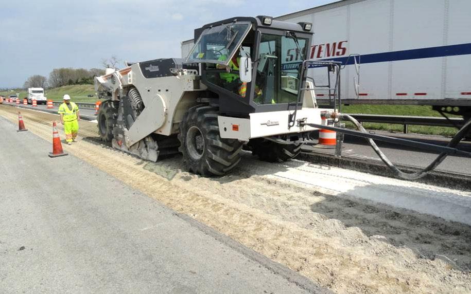
• If structural and/or alignment improvements are required and grade-height restrictions exist, then FDR using a combination of lower layer/subgrade stabilization and CCPR can be considered. In this option, the existing asphalt concrete and underlying quality base materials will be milled off and stockpiled at the nearby cold central plant operation. The remaining roadbed is then stabilized in-place (Figure 3.4) up to a depth of 1 ft (300 mm) with a suitable additive (e.g., portland cement, lime, or a combination of the two depending on material properties), shaped, and compacted. The milled materials are crushed in an impact crusher while the in-place stabilization is being completed, and then processed through the cold central plant with a suitable recycling agent (emulsified or foamed asphalt) before being laid with a paver. Individual lift thicknesses of the CCPR material should not exceed 0.5 ft (150 mm). Excess materials can be used for minor grade corrections, or shoulder widening or addition.
• If extensive vertical and/or horizontal alignment improvements are required and these cannot be accommodated as part of in-place recycling procedures, then CCPR can be considered. In this option, alignment changes can be done as part of the milling and paving operations. Individual lift thicknesses of the CCPR material should not exceed 0.5 ft (150 mm).
46 UCPRC-GL-2020-01
If FDR is considered to be an appropriate recycling strategy, confirm the process or processes that will be used and the depth(s) that will be processed. Then, choose a recycling agent/stabilizer (foamed asphalt or portland cement [emulsified asphalt and lime are currently not specified by Caltrans for FDR]) following the steps discussed in Section 3.3.2 and summarized in Flowchart #4 (Figure 3.8).
3.3 Selecting a Recycling Agent/Stabilizer
3.3.1 Recycling Agents for Partial-Depth Recycling
Recycling agents currently specified by Caltrans for PDR include emulsified asphalt or foamed asphalt, both with cement as an active filler. PDR materials typically do not require, and layers are usually too thin for, stabilization with portland cement. Note that active filler choice is dependent on the chemistry of the material being recycled and should be confirmed during the mix design, if necessary Cement is an appropriate active filler for most California aggregates.
Binding Mechanisms of Partial-Depth Recycling Agents
Although the binding mechanism of each recycling agent is different (i.e., emulsified asphalt coats the aggregates to form a partially bound material, while foamed asphalt droplets “spot weld” fines together to form a mastic that in turn binds to larger aggregates to form a non-continuously bound material), longer-term evaluations in the United States and internationally indicate that both are expected to provide a similar level of performance over the life of the pavement. Asphalt recycling agents physically bond (glue) materials together, without chemical modification, to form a flexible layer with adequate stiffness (275 to 725 ksi) [1,900 to 5,000 MPa]) for supporting traffic during a typical design life. Given that recycling agent contents are typically less than half the asphalt binder contents used in asphalt concrete mixes, PDR material behavior cannot, and
UCPRC-GL-2020-01 47
Figure 3.4: Stabilizing lower layers/subgrade prior to placing a CCPR layer.
should not, be directly compared with that of asphalt concrete, which is considered to be a continuous, fully bound material.

Failure Mechanisms of Partial-Depth Recycled Layers
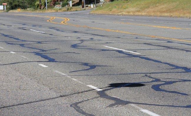
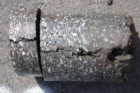
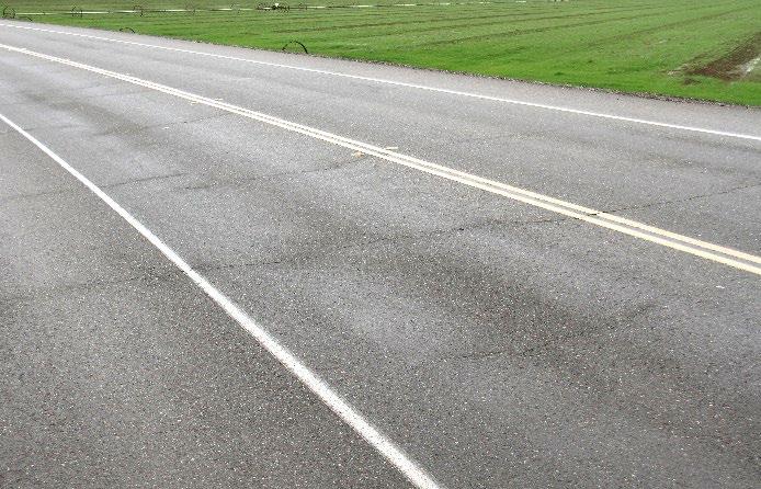
The failure mechanisms of pavement layers recycled with emulsified asphalt and foamed asphalt are essentially the same. Densification of the layer due to the relatively high air-void content may lead to some minor depression in the wheelpaths in the early years after construction (Figure 3.5) on pavements with very thin asphalt concrete surfacings (0.15-ft [45-mm] thick). In the longterm, the partially/non-continuously bound nature of the recycled layer material makes it unlikely that it will fail due to cracks propagating through it. However, tensile strains at the bottom of the recycled layer, caused by repeated traffic loading, will eventually weaken the asphalt bonds in this part of the layer, leading to a gradual loss of stiffness over time. This loss of stiffness in the recycled layer will increase the tensile strains at the bottom of the asphalt concrete surface layers, eventually leading to wheelpath fatigue distress (alligator-A [Figure 3.6] eventually deteriorating to alligator-B if not maintained) similar to conventional flexible pavements with unbound aggregate base layers.
The recycled layer itself is unlikely to fail in fatigue because of the partially-bound/noncontinuously bound nature of the material. A good bond between the recycled layer and the asphalt concrete (i.e., spraying a good tack coat prior to placing the asphalt concrete) is critical for good long-term performance. The rate of deterioration in the recycled layer may also be reduced if a tack coat is applied during paving of this layer (i.e., using a spray paver configuration to apply the tack coat during placement of the recycled layer).
48 UCPRC-GL-2020-01
Figure 3.5: Minor early densification on a PDR project.
Figure 3.6: Alligator-A cracking on a PDR project.
Criteria for Choosing a Recycling Agent for Partial-Depth Recycling
Both types of asphalt recycling agent have some potential limitations that need to be considered when deciding on the most appropriate choice for a given project. These limitations are not common problems on projects and a designer will usually decide which recycling agent to use based on cost or past experience. Alternatively, rather than specifying a particular recycling agent in the bid documents, consideration can be given to allowing the contractor to choose the recycling agent if the specifications allow for this
Potential limitations of using emulsified asphalt on PDR projects include but are not necessarily limited to the following:
• Depending on the emulsion formulation, the cure rate of emulsion-treated layers can be slower than foamed asphalt, which might delay when a road can be opened to traffic. Both rainfall and low temperatures before curing is completed can also slow the cure rate and cause opening delays. Low temperatures, or a large temperature range during a construction shift, may also limit the use of emulsified asphalts on nighttime construction projects in cooler climate zones, if the road has to be opened to traffic soon after a construction shift is completed. Note that contractors will usually work with their emulsion suppliers to ensure that an appropriate emulsion formulation is used to prevent these problems.
• Layers recycled with emulsified asphalt generally cure from the top-down. On thicker layers (e.g., thick than 0.5 ft [150 mm]) and/or during the hottest period of the day some emulsion formulations could break at a faster rate, resulting in a differential rate of curing. This can lead to formation of a “crust” at the top of the layer that could slow the cure rate at the bottom of the layer. Under these conditions, if the road is opened to traffic before the layer has cured completely, rutting/permanent deformation can occur, especially if there is high truck traffic and/or the project includes intersections where vehicle turning actions can shear the material. Note that this problem is not common on PDR projects because of thickness limits. Contractors will usually work with their emulsion suppliers to ensure that an appropriate emulsion formulation is used.
Potential limitations of using foamed asphalt on PDR projects include but are not necessarily limited to the following:
• Higher asphalt temperatures add an increased on-site safety hazard, especially when connecting and disconnecting tankers.
• Use of foamed asphalt requires that the asphalt be maintained at temperatures in the range of 330°F to 350°F (165°C to 175°C). This can be challenging on remote projects with
UCPRC-GL-2020-01 49
long binder haul times, especially if there are any project delays that result in tankers standing idle. Logistical planning is also more critical to ensure that sufficient quantities of binder at the right temperature are available for the day’s production, and that there is no unused binder that will have to be returned to the terminal at the end of the day Maintaining temperature in the tankers can be expensive if required for long periods.
3.3.2 Recycling Agents/Stabilizers for Full-Depth Recycling
Caltrans currently has specifications for FDR with foamed asphalt with cement active filler, and with portland cement only. Emulsified asphalt, although not currently specified, can also be an appropriate recycling agent.
Because foamed asphalt and portland cement have considerably different binding mechanisms, they should not be considered as equal or interchangeable when deciding which is a suitable recycling agent/stabilizer for FDR. The key differences between the two are summarized below.
Target use of Recycling Agents/Stabilizers in Full-Depth Recycling Applications
The target uses of asphalt recycling agents and cementitious stabilizers in FDR projects include the following:
• Foamed asphalt and emulsified asphalt recycling agents are best suited for recycling good quality materials found in the engineered layers of the pavement (i.e., recycling primarily asphalt concrete and underlying aggregate base, or asphalt concrete over previously cement-treated layers that have reverted to an equivalent granular state). These materials would typically classify as well graded gravel (GW), poorly graded gravel (GP), and potentially silty gravel (GM) in the Unified Soil Classification System, depending on percent passing the #200 sieve (0.075 mm) and the plasticity index.
• Portland cement is best suited for stabilizing and improving marginal recycled materials (i.e., recycling relatively thin asphalt concrete layers over marginal gravel or subgrade materials, or for stabilizing marginal lower layers and/or subgrade in a two-part recycling operation. This entails removing and stockpiling the upper layers; stabilizing the lower layers with cement, lime, or a combination of the two depending on material properties; and then, after the upper layer materials have been processed in a cold central plant, paving them on top of the stabilized layer).
Binding Mechanisms of Full-Depth Recycling Agents/Stabilizers
• The binding mechanisms of asphalt recycling agents in FDR applications will be the same as those for PDR applications, as explained in Section 3.3.1.
50 UCPRC-GL-2020-01
• Portland cement will either chemically modify or stabilize the materials (i.e., plasticity reduction and/or temporary strength and stiffness increase, or permanent strength and stiffness increase, respectively). Strength and stiffness increases on stabilized FDR layers are usually significant (e.g., more than 1,500 ksi [10,000 MPa] on marginal recycled materials), and increase with increasing quality of the material being stabilized (e.g., stabilizing a 50/50 asphalt concrete/aggregate base blend with four percent cement typically results in an initial stiffness of around 3,000 ksi [≈ 20,000 MPa]). Consequently, FDR layers where cement is used as the stabilizing agent should be considered as bound, semi-rigid rather than flexible in the pavement design.
Failure Mechanisms of Full-Depth Recycled Layers
• The failure mechanisms of FDR layers treated with asphalt recycling agents will be the same as those in PDR pavements, as explained in Section 3.3.1
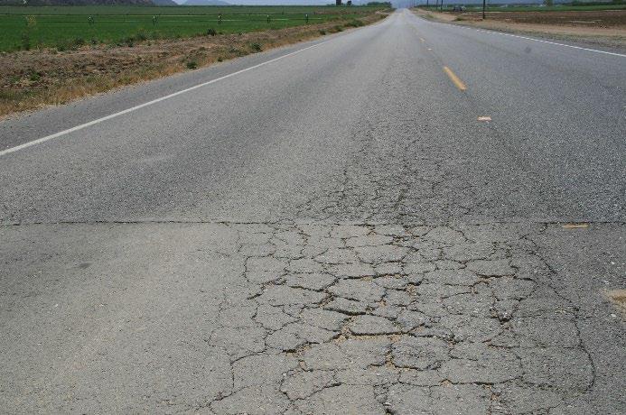
• The failure mechanisms of FDR layers with cement stabilization (FDR-C) are the same as those for conventional pavement designs with cemented layers. Early distresses are usually related to shrinkage cracks that reflect through the asphalt concrete (Figure 3.7), which in turn leads to wheelpath cracking on either side of the reflected cracks. Shrinkage cracks can be mitigated, but not prevented, by limiting design unconfined compressive strengths (e.g., 300 to 450 psi [2.1 to 3.1 MPa]) and by “microcracking” the compacted recycled layer with two or three passes of a 12-ton roller at maximum vibration between 48 and 56 hours after completion of compaction (12,13). This type of shrinkage crack mitigation is generally not effective on layers with high compressive strengths (i.e., 7-day UCS strengths higher than 600 psi [4.1 MPa]).
In the longer-term, tensile strains at the bottom of the recycled layer, caused by repeated traffic loading, will eventually lead to fatigue cracks in that layer that will also eventually reflect through the asphalt concrete surfacing. A good bond between the recycled layer and the asphalt concrete

UCPRC-GL-2020-01 51
Figure 3.7: Reflected shrinkage cracks on FDR-C projects.
(i.e., a good tack coat prior to placing the asphalt concrete) is critical for good long-term performance. Debonding caused by problems on the surface of the recycled layer can also lead to early distresses in the asphalt concrete layers. Examples of the causes of these problems include inappropriate mix designs (insufficient cement resulting in modification rather than permanent stabilization), poor construction techniques (e.g., adding material during final shaping, and/or delayed compaction), poor curing procedures (e.g., multiple wetting and drying cycles which can lead to carbonation of the surface), or irreversible damage caused during incorrect microcracking procedures. An introduction to carbonation in cement-treated layers is provided in Appendix A).
Criteria for Choosing a Recycling Agent/Stabilizer for Full-Depth Recycling
Based on the differences described above, the following criteria should be taken into consideration when choosing a recycling agent/stabilizer for FDR (summarized in Figure 3.8):
• If the recycled materials are asphalt concrete and aggregate base (well graded gravel [GW], poorly graded gravel [GP], and in some instances, silty gravel [GM] in the Unified Soil Classification System), then use foamed asphalt (or emulsified asphalt if a specification is available) with an active filler (typically portland cement in California).
+ If choosing between foamed asphalt and emulsified asphalt, then consider the potential limitations of each that are listed below.
+ If the combined materials that will be recycled classify as silty gravel and the percent passing the #200 sieve (0.075 mm) exceeds 15 percent, then consider using portland cement.
• If the recycled materials comprise a relatively thin asphalt concrete layer over marginal materials (i.e., the combined materials do not classify as well graded or poorly graded gravel, and silty gravels have high fines contents [the percent passing the #200 sieve (0.075 mm) exceeds 15 percent]) then consider using portland cement.
• Using the plasticity index, pH, and UCS test results from the project investigation (see Section 2.4.8), review the following if portland cement treatment is being considered:
+ If the combined materials have a plasticity index of 20 or higher and classify as clayey sand (SC), lean clay (CL), elastic silt (MH), or fat clay (CH), consider using a combination of lower-layer stabilization with cement, lime, or a combination of the two, followed by paving with cold central plant asphalt-treated materials in the upper layer(s)
52 UCPRC-GL-2020-01
+ If the UCS determined with the cement content required to achieve a constant pH in the initial consumption of stabilizer test, plus 1 percent, does not exceed the specified strength limit (the suggested limit is 450 psi [3.1 MPa]), then use portland cement.
+ If the UCS determined with the cement content required to achieve a constant pH in the initial consumption of stabilizer test, plus 1 percent, exceeds the specified strength limit, then the FDR strategy should be reviewed. Options include the following:
Adding supplemental materials to improve the properties so that an asphalt recycling agent can be used.
Using a combination of lower-layer stabilization with cement, lime, or a combination of the two, followed by paving with cold central plant asphalttreated materials in the upper layer(s)
UCPRC-GL-2020-01 53
Figure 3.8: Flowchart #4: Selecting a recycling agent/stabilizer for full-depth recycling.
FDR Recycling Agent Selection Yes No Review all investigation results, specifically laboratory test results of combined recycled materials Is material primarily RAP and aggregate base ? Yes Yes From Flowchart #3 Does material meet Class 2 or Class 3 AB specifications? Does material meet USCS GW, GP, or GM classification? Is percent passing #200 < 15% Consider portland cement Consider foamed asphalt (or emulsified asphalt if specification is available) No No No Yes Is UCS with ICS + 1% cement < 450 psi? Consider CCPR with asphalt recycling agent with lower layer/ subgrade stabilization Yes No Is plasticity index < 6? No Review pH and UCS test results for cement treatment done during project investigation Yes Is plasticity index > 20? No Yes
Note that this guide does not recommend increasing the recycling depth to incorporate more marginal-quality subgrade materials into the mix to meet pH and UCS requirements for portland cement stabilization.
• If any supplemental materials include crushed recycled portland cement concrete, then consider foamed asphalt (or emulsified asphalt) with an active filler. Note that crushed concrete can contain considerable amounts of unhydrated or partially hydrated cement that can rehydrate during watering and compaction, resulting in a recycled layer that could exceed unconfined compressive strength (UCS) limits that will have semi-rigid pavement behavior rather than flexible pavement behavior.
Potential Limitations of Emulsified and Foamed Asphalt on Full-Depth Recycling Projects
Caltrans specifications currently only allow the use of foamed asphalt if an asphalt recycling agent will be used for FDR. This may change in the future and designers should be aware of potential limitations that need to be considered when deciding on the most appropriate choice for a given project. These limitations are not common problems on projects and a designer will usually decide which recycling agent to use based on cost or past experience. Alternatively, rather than specifying a particular recycling agent in the bid documents, consideration can be given to allowing the contractor to choose the recycling agent if the specifications allow for this.
Potential limitations of using emulsified asphalt on FDR projects include but are not necessarily limited to the following:
• Emulsified asphalt typically consists of at least 60 percent asphalt and 40 percent emulsifier. Consequently, more fluid compared to foamed asphalt (where compaction water content can be controlled) could be added during the recycling process if similar residual asphalt binder contents are used (note that optimum residual asphalt binder contents are often about 0.2 to 0.5 percent lower for emulsified asphalt mix designs compared to those for foamed asphalt mix designs). Potentially higher fluid contents should be a consideration on projects using emulsified asphalt in thick recycled layers (i.e., thicker than 0.5 ft [150 mm]) because on pavement layers with high in-situ moisture contents (e.g., on severely distressed pavements, especially after rainfall), the total fluid content may exceed the optimum compaction moisture content of the materials. Although the active filler may absorb some of the water, higher than optimum moisture contents in the layer can delay compaction and opening to traffic while the material dries back to an acceptable level.
• Layers recycled with emulsified asphalt generally cure from the top-down. On thicker layers (i.e., thicker than 0.5 ft [150 mm]) and/or during the hottest period of the day some
54 UCPRC-GL-2020-01
emulsion formulations could break at a faster rate, resulting in a differential rate of curing. This can lead to formation of a “crust” at the top of the layer that could slow the cure rate at the bottom of the layer. Under these conditions, if the road is opened to traffic before the layer has cured completely, rutting/permanent deformation can occur, especially if there is high truck traffic and/or the project includes intersections where vehicle turning actions can shear the material.
• Depending on the emulsion formulation, the cure rate of emulsion-treated layers can be slower than foamed asphalt, which might delay when a road can be opened to traffic. Both rainfall and low temperatures before curing is completed can also slow the cure rate and cause opening delays. Low temperatures, or a large temperature range during a construction shift, may also limit the use of emulsified asphalts on nighttime construction projects in cooler climate zones, if the road has to be opened to traffic soon after a construction shift is completed. Note that contractors will usually work with their emulsion suppliers to ensure that an appropriate emulsion formulation is used to prevent these problems.
Potential limitations of using foamed asphalt on FDR projects include but are not necessarily limited to the following:
• Higher asphalt temperatures add an increased on-site safety hazard, especially when connecting and disconnecting tankers.
• Use of foamed asphalt requires that the asphalt be maintained at temperatures in the range of 330°F to 350°F (165°C to 175°C). This can be challenging on remote projects with long binder haul times, especially if there are any project delays that result in tankers standing idle. Logistical planning is also more critical to ensure that sufficient quantities of binder at the right temperature are available for the day’s production, and that there is no unused binder that will have to be returned to the terminal at the end of the day. Maintaining temperature in the tankers can be expensive if required for long periods.
3.3.3 Additional Information About Recycling Agents and Stabilizers
Table 3.2 summarizes the likely choices of recycling agent or stabilizer in terms of the ASTM Unified Soil Classification System (ASTM D2487) and the AASHTO Soils and Soil-Aggregate Mixture Classification System (AASHTO M 145). A schematic summarizing the expected behavior of different recycling agents, stabilizers, and recycling agents with active filler is shown in Figure 3.9
UCPRC-GL-2020-01 55
3.4 Record of Decision
Document the proposed recycling strategy and choice of recycling agent/stabilizer in the design documentation.
Table 3.2: Example Recycling Agent/Stabilizer Choice for Different FDR Materials
■■■ Appropriate if meets specifications or guidance-recommended minimum and maximum limits.
■■ Usually not appropriate due to not meeting specifications or guidance-recommended minimum and maximum limits.
■ Generally not appropriate and unlikely to meet specifications or guidance recommendations, or will not be economical.
a USCS = Unified Soil Classification System
b P200 = Percent passing #200 sieve
c PI = Plasticity Index
d Emulsified asphalt is currently not specified by Caltrans for FDR projects
e SO4 = Sulfate
f Lime is currently not specified by Caltrans for FDR projects. Note that FDR on high plasticity materials (PI>20) is not recommended. CCPR in combination with lower layer stabilization can be considered as an alternative.
56 UCPRC-GL-2020-01
Material Type Material Description Classification Foamed Asphalt P200 = 5 – 15b PI < 6c Emulsifiedd Asphalt P200 = 5 – 15 PI < 6 Portland Cement P200 ≥20 PI < 20 SO4 < 3,000 ppme Limef P200 >25 PI ≥ 20 SO4 < 3,000 ppm USCSa AASHTO AC plus Good Base Well Graded Gravel GW A-1-a ■■■ ■■■ ■■ ■ Poorly Graded Gravel GP A-1-a ■■■ ■■■ ■■ ■ AC plus Marginal Base Silty Gravel GM A-1-b ■■■ ■■■ ■■■ ■ Clayey Gravel GC A-1-b A-2-6 ■■ ■■ ■■■ ■ Subgrade Well Graded Sand SW A-1-b ■■ ■■ ■■■ ■ Poorly Graded Sand SP A-3 or A-1-b ■■ ■■ ■■■ ■ Silty Sand SM A-2-4 or A-2-5 ■■ ■■ ■■■ ■ Clayey Sand SC A-2-6 or A-2-7 ■ ■ ■■■ ■■■ Silt or Silt with Sand ML A-4 or A-5 ■ ■ ■■■ ■ Lean Clay CL A-6 ■ ■ ■■■ ■■■ Organic Silt/ Organic Lean Clay OL A-4 ■ ■ ■ ■ Elastic Silt MH A-5 or A-7-5 ■ ■ ■ ■■■ Fat Clay, Fat Clay With Sand CH A-7-6 ■ ■ ■ ■■■
Presumed
UCPRC-GL-2020-01 57
None Low (1 – 2%) Intermediate (2 – 4 %) High (>4%) High (4 - 6%) Intermediate (2 - 4%) Low (1 – 2%) Strongly cemented/ stabilized Lightly cemented/ stabilized Asphalt concrete (HMA) Unbound aggregate base Portland cement concrete Very high (>8%) None Increasing flexibility of recycled layer Increasing rigidity of recycled layer
Figure
3.9: Basic characteristics of in-place recycled pavement materials (18).
impractical or not economically viable
or foamed asphalt with cement Cement content
binder content
behavior Stressdependent behavior Stiff, brittle behavior
cement
modified
Emulsified
Asphalt
Temperature dependent, viscoelastic
Emulsified or foamed asphalt with no
Cement-
58 UCPRC-GL-2020-01 Blank page
4. PAVEMENT DESIGN
4.1 Introduction
Caltrans is currently transitioning from using empirical, gravel equivalence design procedures to using mechanistic-empirical design procedures for both new construction and rehabilitation. Gravel equivalence and layer coefficient designs using assigned gravel factors or layer coefficients for recycled materials are not recommended for CAPM or rehabilitation designs in California because they do not necessarily provide a realistic indication of long-term performance and the outcomes are primarily influenced by individual layer type and thickness rather than the performance properties of the entire pavement structure.
The Caltrans mechanistic-empirical design analysis software (CalME) includes in-place recycling options for CAPM, rehabilitation, and as an alternative to reconstruction. Options for using CCPR materials when designing new projects are also provided. CalME can be accessed via the Internet at www.ucprc.ucdavis.edu/calme. Users are required to register and to complete a training module with the Caltrans Office of Asphalt Pavement, before they can log in and start a design.
4.2 Mechanistic-Empirical Design Analysis (CalME)
This section covers input specific to CAPM and rehabilitation projects where partial-depth (PDR), full-depth (FDR), or cold central plant recycling (CCPR), or a combination of CCPR and lower layer and/or subgrade stabilization, is being considered. Apart from choosing an appropriate layer and material type for the recycling project, no specific additional steps are required for doing a CalME design analysis of a pavement structure with recycled layers.
Note that CalME is under constant development and refinement as new performance data is collected and default data (e.g., modulus for different materials) and performance models are refined and updated. The information provided and screen shots shown in this chapter were current as of this writing, but they may change as the software is developed, refined, and updated.
4.2.1 Project Setup
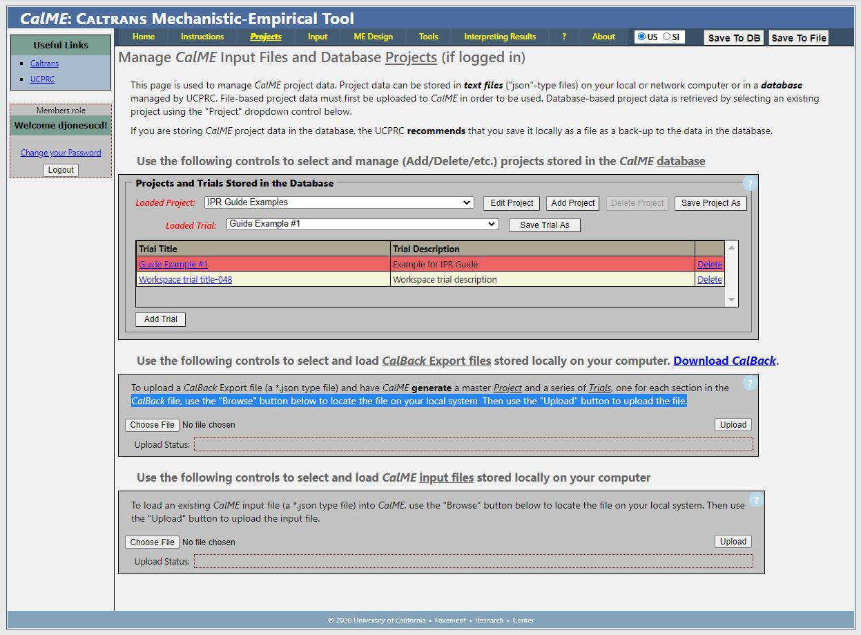
Project setup entries (under the “Projects” tab in the CalME menu ribbon [Figure 4.1]) follow standard CalME procedures for any type of project and are not discussed in this guide.
UCPRC-GL-2020-01 59
4.2.2 Adding Project Information
The “Input” tab in the CalME ribbon, has two options in the drop down menu, namely “Project Information” and “Simulation Parameters ” This section covers project information. Entries for “Project Location,” “Traffic Count Information,” “Climate,” and “Design Lane Traffic Loads” follow standard CalME procedures and are not discussed in this guide. Note that once the District, County, Route, Direction, and Post Mile information have been selected from dropdown menus, information stored in the databases will automatically populate the remaining fields (example in Figure 4.2). These can be edited if required. The default design life is 20 years, but this can be changed to 10 years or less for CAPM design analyses.
60 UCPRC-GL-2020-01
Figure 4.1: CalME project setup screen.
Pavement Structure: Layer Type
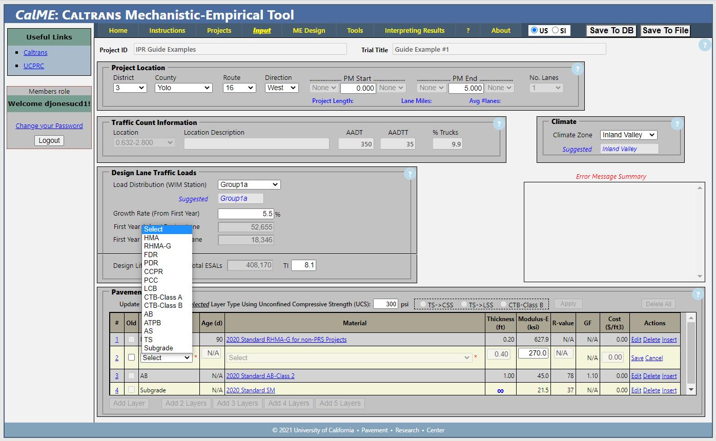
In the “Pavement Structure” subsection, the following options for in-place recycling are included in the “Layer Type” dropdown menu (Figure 4.3).
• PDR (recycled in-place using a recycling train)
• FDR (recycled in-place using a recycling train)
• CCPR. Select this option as follows:
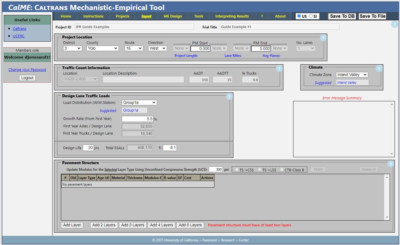
+ For PDR and FDR projects where CCPR materials will be used and/or the total layer thickness is thicker than the maximum assigned to PDR and FDR layers by CalME (see “Layer Thickness” discussion below).
+ For projects where a combination of CCPR and lower layer/subgrade stabilization is being considered. In this instance, a TS (treated subgrade) layer will need to be included as the stabilized “Layer Type” below the CCPR layer. A subgrade layer below the TS layer will still be required as the last layer in the structure, consistent with any CalME design.
+ If processed RAP from a stockpile, with or without supplemental aggregates/fines, is being considered for a base in new construction, reconstruction, or lane addition.
Use the data and observations from the project investigation to add the existing layers that will remain below the recycled layer. The following general “rules” should be followed:
• PDR layers
+ May not have any new layers beneath it, as these would be impossible to accommodate. Use the CCPR option if stabilized lower layers and/or subgrade are being considered.
UCPRC-GL-2020-01 61
Figure 4.2: CalME project information input screen.
+ Can have an old HMA layer below the PDR layer, but it is not required to do a design. Add an old HMA layer under the PDR layer only if that HMA layer is thicker than 0.1 ft, intact (i.e., no alligator-B cracking), and bonded to the base layer beneath it (determined from investigation cores).
+ Pavements with thin, badly cracked HMA layers less than 0.2-ft thick beneath a PDR layer should not be considered as this will lead to debonding of the PDR layer from the underlying base, leading to early pavement distress. CalME will not accurately model this distress. Options for dealing with this situation are discussed in Section 3.2.
• FDR layers
+ May not have any new layers beneath it, as these would be impossible to accommodate Use the CCPR option if stabilized lower layers and/or subgrade are being considered.
+ May not have an old HMA layer beneath it. Use the PDR option if an HMA layer will remain below the recycled layer.
• CCPR layers

+ Can have both old and new layers beneath it.
+ Add an old HMA layer under the CCPR layer only if that HMA layer is thicker than 0.1 ft, intact (i.e., no alligator-B cracking), and bonded to the base layer beneath it.
+ Pavements with thin, distressed old HMA layers less than 0.2 ft thick beneath a CCPR layer should not be considered as this will lead to debonding of the CCPR layer from the underlying base, leading to early pavement distress. CalME will not accurately model this distress. Options for dealing with this situation are discussed in Section 3.2.
62 UCPRC-GL-2020-01
Figure 4.3: CalME in-place recycling options for “Layer Type.”
Note that if grade-height restrictions on rehabilitation projects dictate that all of the asphalt concrete, and potentially some of the underlying aggregate base, is milled off and removed from the site prior to starting any recycling work, then the project should be considered as reconstruction and not as FDR. In these instances, the pavement should be designed following the HDM procedures for reconstruction. Stabilization of any remaining unbound layers and/or the subgrade should be considered and designed as a stabilized base or subbase (CTB or LCB) or treated soil (TS)
Pavement Structure: Material Type
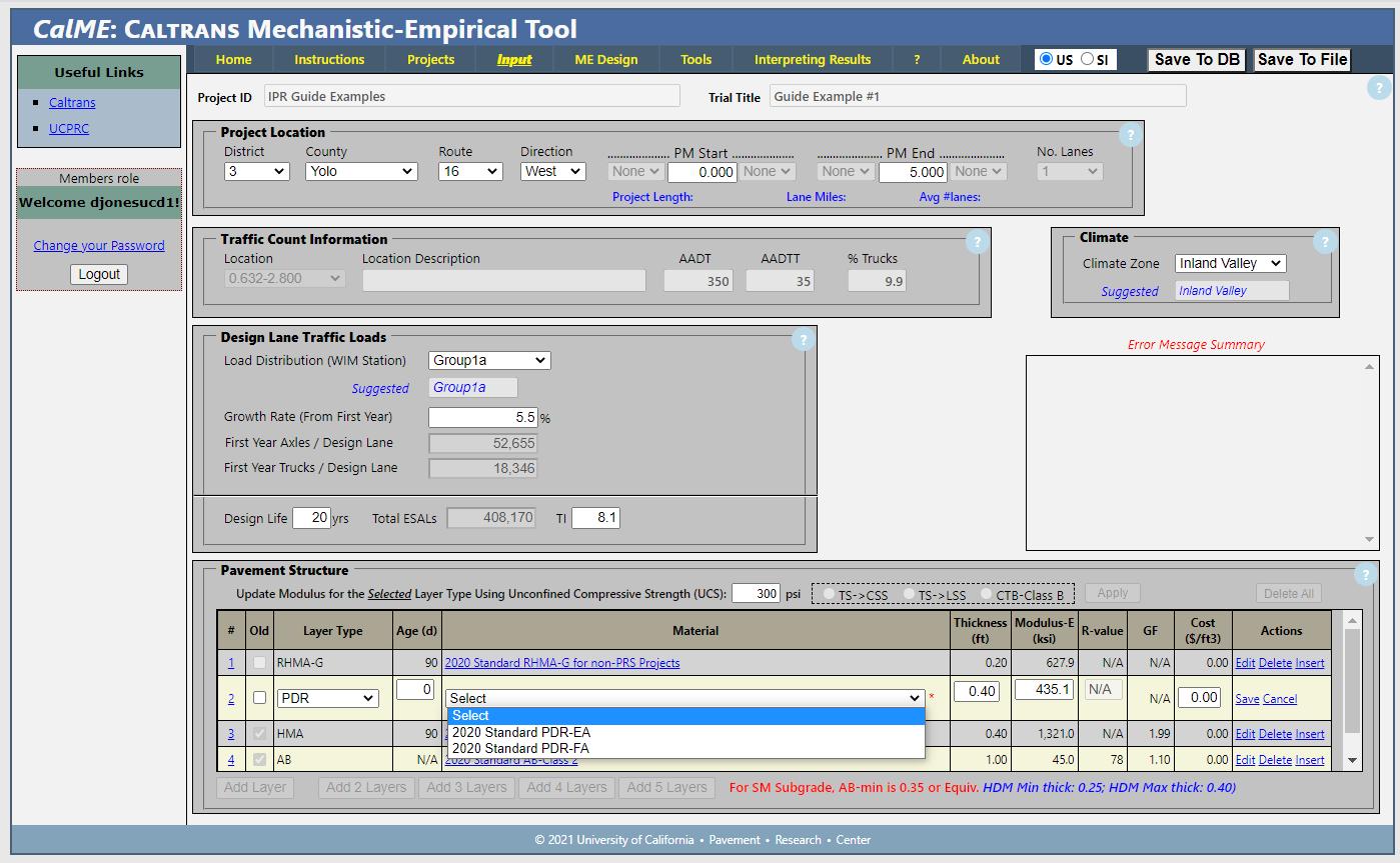
One or more materials types are assigned to each layer type and the desired “Material” type must be selected from the dropdown menu next to each selected layer (examples in Figure 4.4 through Figure 4.6). The following material options for recycled “Layer Type” are included. Note that the lists are alphabetical and do not imply any preferences. “Standard” implies that the layers are designed and built to meet current Caltrans specifications.
• PDR
+ 2020 Standard PDR-EA (typically 100 percent RAP with maximum 1 percent active filler).
+ 2020 Standard PDR-FA (typically 100 percent RAP with maximum 1 percent active filler).
• FDR
+ 2020 Standard FDR-C (RAP and portion of underlying layers. Although current Caltrans FDR-C specifications currently specify a design unconfined compressive strength range of 300 to 600 psi (2.1 to 4.1 MPa), a range of 300 to 450 psi (2.1 to 3.1 MPa) should be targeted to minimize the risk of shrinkage cracking.
+ 2020 Standard FDR-FA (RAP and portion of underlying layers, with maximum 1 percent active filler).
+ 2020 Standard FDR-N (RAP and portion of underlying layers with no recycling agent or stabilizer).
• CCPR
+ 2020 Standard CCPR-C (RAP and portion of underlying layers Although current Caltrans FDR-C specifications currently specify a design unconfined compressive strength range of 300 to 600 psi (2.1 to 4.1 MPa), a range of 300 to 450 psi (2.1 to 3.1 MPa) should be targeted to minimize the risk of shrinkage cracking).
+ 2020 Standard CCPR-EA (Material dependent on application. For PDR, typically 100 percent RAP with maximum 1 percent active filler. Supplemental fines can be considered. For FDR, typically RAP and a portion of the underlying layers, with maximum 1 percent active filler). 2020 Standard CCPR-FA (Material dependent on application. For
UCPRC-GL-2020-01 63
PDR, typically 100 percent RAP with maximum 1 percent active filler. Supplemental fines can be considered. For FDR, typically RAP and a portion of the underlying layers, with maximum 1 percent active filler).
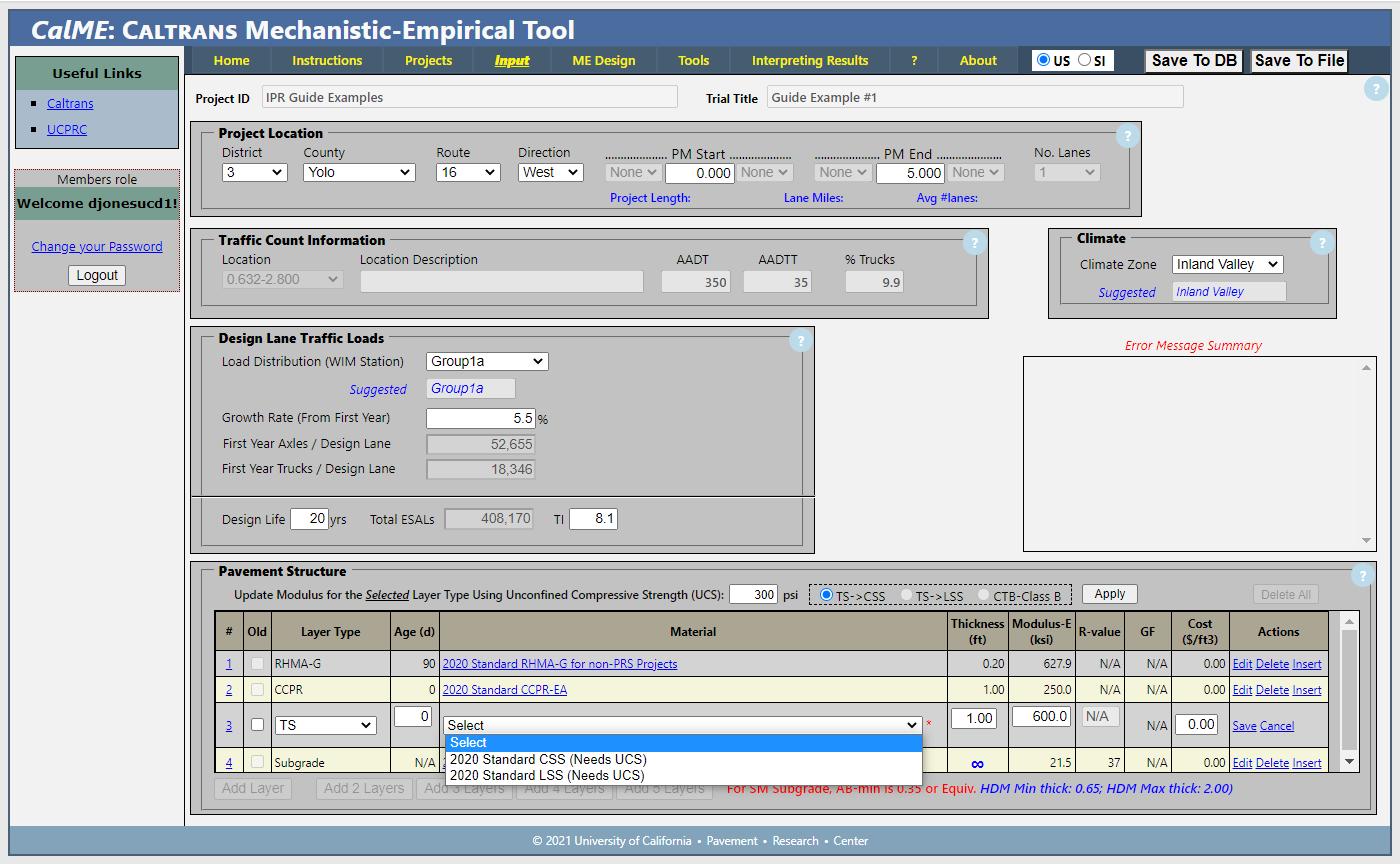
+ Note that if these options are used in conjunction with lower-layer stabilization, then the choice of cement-stabilized soil (CSS) or lime-stabilized soil (LSS) will need to be selected as the “Material” for the TS layer (example in Figure 4.7).

64 UCPRC-GL-2020-01
Figure 4.4: CalME in-place recycling options for PDR “Material.”
Figure 4.5: CalME in-place recycling options for FDR “Material.”
Pavement Structure: Layer Thickness
After selecting the “Material,” enter the layer thicknesses for each layer in the “Thickness” column (examples in Figure 4.4 through Figure 4.7). The recycled and underlying layer thicknesses will be based on the information collected during the site investigation (coring and DCP tests). The recycled layer thickness can be adjusted in a series of iterations during the design. However, if the recycled layer used in the design is thicker than what was anticipated during the site investigation, it is important for the designer to ensure that there is sufficient material in place that can be recycled to that thickness. CalME has the following layer thickness limits:

UCPRC-GL-2020-01 65
Figure 4.6: CalME in-place recycling options for CCPR “Material.”
Figure 4.7: CalME in-place recycling options for TS “Material” used in conjunction with CCPR.
• PDR
+ Allowable thickness range of 0.25 to 0.5 ft (75 to 150 mm), consistent with Caltrans standard specifications.
• FDR
+ Allowable thickness range of 0.5 to 1.0 ft (150 to 300 mm). Note that minimum thickness for FDR-C layers should be 0.7 ft (210 mm). FDR-C layer thickness can be increased to 1.5 ft (450 mm) under certain circumstances on specific projects with Office of Asphalt Pavement approval.
• CCPR
+ Minimum thickness limit of 0.25 ft (75 mm) for CCPR-EA and CCPR-FA and 0.7 ft (210 mm) for CCPR-C layers. CCPR does not have a maximum layer thickness limit because CCPR material can be placed in multiple layers, with maximum thickness of each layer dictated by the specifications.
Selecting layer thicknesses, especially asphalt concrete layer thicknesses on PDR and FDR projects, is an iterative process and a number of runs may be necessary to determine the optimal thicknesses for ensuring that rutting and cracking life in the surface layer are optimized.
Pavement Structure: Modulus/Stiffness
Once a material is selected, a default modulus for it will appear in the adjacent cell in the “Modulus-E” column (examples in Figure 4.4 through Figure 4.7). This default value can be changed if project specific information is available, or if the designer has experience and/or the data for local materials. The default values for recycled materials are based on limited stiffness data (falling weight deflectometer and dynamic modulus laboratory tests on cores) collected from a range of PDR and FDR projects across California and checked against results from other states and the National Center for Asphalt Technology.
4.2.3 Choosing Simulation Parameters and Running the Simulations
The remaining steps to come up with an appropriate design follow standard CalME procedures and include the following:
1. Choosing the “Simulation Parameters” under the “Input” tab,
2. Running the simulation under the “ME Design” tab, and
3. Revising the pavement design and rerunning the simulation until an appropriate design is achieved.
These steps are covered during CalME training and are not discussed in this guide.
66 UCPRC-GL-2020-01
4.3 Gravel Equivalence (CalFP) and Layer Coefficient (AASHTO-93) Designs
Gravel equivalence designs should follow the procedures described in Section 630 of the HDM (1). Note that the current Caltrans gravel factors for in-place recycled materials are based on limited empirical data from early PDR projects with emulsified asphalt and FDR projects with foamed asphalt, and are considered to be conservative. Gravel factors for FDR projects with cement are derived from a formula originally developed to calculate the gravel factor of a stabilized soil used as a substitute for an aggregate subbase, and they are not necessarily representative of the asphalt concrete and aggregate base materials that would typically be recycled on Caltrans projects. Consequently, procedures using any of these gravel factors may result in conservative designs that have thick asphalt concrete surfacing layers.
Suggested revised gravel factors for in-place recycled materials were developed as part of the development of performance models for recycled materials for CalME (10). At the time of preparing this guide, these revised gravel factors had not been incorporated into the HDM. Therefore, the current values in the HDM should still be used unless permission is obtained from the Office of Asphalt Pavement to use the suggested values The suggested revised gravel factors are summarized in Table 4.1.
Table 4.1: Suggested Revised Gravel Factors for In-Place Recycled Materials
a Equation developed for stabilized soil that is substituted for aggregate subbase. Valid only for UCS of 300 psi and higher after 28-day cure, or 7-day modified cure.
b Valid for UCS range between 300 and 600 psi, but target range of 300 to 450 psi is recommended. Caltrans does not use the AASHTO-93 pavement design procedure and it is therefore not covered in this guide. The layer coefficients for layers with emulsified or foamed asphalt typically range between 0.30 and 0.35.
4.4 Plans
The plans for in-place recycling projects are similar to projects using other CAPM and rehabilitation strategies. The layout plans should show the existing roadway and the limits of
UCPRC-GL-2020-01 67
Material Current Gravel Factor Suggested Gravel Factor PDR-EA 1.5 1.6 PDR-FA 1.5 1.6 FDR-FA 1.4 1.6 FDR-C 0.9 + (UCS / 1000)a 1.7b FDR-N if RAP ≥ 60% of recycled material 1.2 1.2 FDR-N if RAP < 60% of recycled material 1.1 1.1
recycling (width and length). The typical cross sections should clearly show the cross slope, width, and depth of the existing pavement layers, recycled layers, stabilized layers if these have been done together with CCPR layers, and new surfacing layers. If survey data is not available and superelevation diagrams are not provided, indicate “match existing” cross slope and the contractor will reference the existing profile along the roadway centerline.
The construction details should include conforming transverse tapers where the recycled pavement structure ties into existing or new roadway. Quantity sheets should include the stationing and corresponding recycled areas and recycling agent, stabilizer, active filler, supplemental aggregate if used, emulsified asphalt curing seal, and sand cover amounts in the roadway items table.
4.5 Estimation of Quantities and Costs
The estimation process for recycling cost must consider several project specific features such as location, length, schedule, geometrics, traffic handling, as well as recycled depth and area, and if applicable, stabilized depth and area if CCPR is done together with lower layer/subgrade stabilization. The Caltrans Unit Cost Database currently has information for FDR projects only (Item Codes 300100 through 304400). Costs for lower layer/subgrade stabilization (cement or lime) can be estimated from Item Codes 240100 through 240300). Bid items for recycling projects usually include the following:
• Recycling (area in square yards)
• Asphalt recycling agent or cementitious stabilizer (tons)
• Active filler (tons) (only on projects using asphalt recycling agents)
• Asphaltic emulsion curing seal (tons)
• Sand cover (tons)
• Mix design (lump sum, which includes work for material sampling, traffic control during material sampling, and laboratory testing)
• Supplementary aggregate if required in the design (tons)
Contractor costs factored into the bid include, but are not limited to, mobilization, quality control testing, and temporary striping. Working days/production rates are difficult to generalize on because of the different types of equipment used, recycling depth and width, road geometry,
68 UCPRC-GL-2020-01
and what work is done by the recycling sub-contractor and what work is done by the prime contractor.
4.5.1 Estimation of Quantities Examples
Two examples below show how the quantities for two two-lane in-place recycling projects are estimated Both projects are 10 miles long and the recycling width is 24 ft. The unit weight of the recycled material on both projects is 140 lb/ft3.
PDR Project with Foamed Asphalt and Cement Active Filler (PDR-FA)
Recycling area is 52,800 × 24 = 1,267,200 ft2 (140,800 yd2) and recycling depth is 0.33 ft.
• Recycling
+ 1,267,200 × 0.33 = 418,176 ft3
+ Convert to cubic yards: 418,176 / 27 = 15,488 yd3
+ Rounded result value = 15,500 yd3
• Asphalt binder
+ 2.5% foamed asphalt content
+ 1,267,200 × 0.33× 0.025× 140 = 1,463,616 lb
+ Convert to tons: 1,463,616 / 2,000 = 731.8
+ Rounded result value = 732 tons
• Cement
+ 1.0% cement active filler content
+ 1,267,200 × 0.33 × 0.01 × 140 = 585,446 lb
+ Convert to tons: 585,446 / 2,000 = 292.7
+ Rounded result value = 293 tons
• Curing seal + SS1H cut 50/50 @ 0.15 gal/yd2
+ 140,800 × 0.15 = 21,120 gal
+ Convert to tons: 21,120 / 242 = 87.3
+ Rounded result value = 88 tons
• Sand cover + 1.5 lb/yd2 + 140,800 × 1.5 = 211,200
+ Convert to tons: 211,200 / 2,000 = 105.6
+ Rounded result value = 106 tons
FDR Project with Portland Cement (FDR-C)
Recycling area is 52,800 × 24 = 1,267,200 ft2 (140,800 yd2) and recycling depth is 1 ft.
UCPRC-GL-2020-01 69
• Recycling + 1,267,200 × 1 = 1,267,200 ft3
+ Convert to cubic yards: 1,267,200 / 27 = 46,934 yd3
+ Rounded result value = 46,934 yd3
• Cement + 3.0% cement
+ 1,267,200 × 1 × 0.03 × 140 = 5,322,240 lb
+ Convert to tons: 5,322,240 / 2,000 = 2,661.1
+ Rounded result value = 2,662 tons
• Curing seal + SS1H cut 50/50 @ 0.15 gal/yd2
+ 140,800 × 0.15 = 21,120 gal
+ Convert to tons: 21,120 / 242 = 87.3
+ Rounded result value = 88 tons
• Sand cover
+ 1.5 lb/yd2
+ 140,800 × 1.5 = 211,200
+ Convert to tons: 211,200 / 2,000 = 105.6
+ Rounded result value = 106 tons
4.6 Life Cycle Cost Analysis
Life cycle cost analysis (LCCA) applies a set of economic principles to evaluate long-term alternative investment options. LCCA provides a transparent life cycle cost (LCC) comparison of alternatives as one of the criteria for decision-making regarding alternative selection. The analysis enables LCC comparison of competing design alternatives to meet a required functionality.
Caltrans requires that an LCCA be performed and documented for almost every project that includes pavement work on the State Highway System, regardless of the project’s funding source. The exceptions to this requirement are major maintenance, minor A and minor B maintenance, encroachment permits, projects that use permit engineering evaluation reports, maintenance pullouts, landscape paving, and emergency work.
70 UCPRC-GL-2020-01
The Caltrans LCCA process, which is guided by the Caltrans LCCA Procedures Manual and completed using the Caltrans version of the RealCost software accounts for the following costs that are expected to occur over the duration of the analysis period (22):
• Direct costs to Caltrans (contracted materials and work) for the initial construction, future contracted maintenance and rehabilitation, and annualized routine maintenance costs
• Indirect costs to Caltrans (overhead, project administration)
• Road user costs due to construction work zone traffic delay during initial construction and future maintenance and rehabilitation
Cost estimates for the analysis come from different sources. The initial cost is estimated by the designer. The timing of future maintenance and rehabilitation (M&R) and annual routine maintenance activities and their costs are taken from the M&R tables in the Caltrans LCCA Procedures Manual (22). It should be noted that as of the timing of this writing, the current (2013) manual does not cover in-place pavement recycling, but updates to the manual and the RealCost software that include in-place pavement recycling are in progress and are scheduled to be available in the fall of 2020. Performance information from the Caltrans Automated Pavement Condition Survey (APCS) for completed in-place recycled projects, combined with mechanisticempirical simulation, will be used as the basis for these updates.
The timing of future maintenance and rehabilitation activities and what types of these activities will occur within the life cycle analysis period are key considerations in project selection because of their influence on life cycle costs. Life cycle cost is reduced when the initial treatment lasts longer, when the costs of future treatments are discounted to a present value (PV), and when the types of future treatments have less cost.
Typical elements of an LCCA that compares an in-place recycling strategy with an alternative CAPM or rehabilitation strategy could include but are not limited to comparisons of the following:
• Quantities of new virgin aggregate used. Typically, in-place recycling recycles all existing materials in place, eliminating the need for new virgin aggregates unless major structural increases are required as part of the design. All in-place recycled projects do require an asphalt concrete surfacing.
• Thickness of new asphalt concrete used. Structural capacity can often be increased during recycling by choosing an optimal recycling strategy and recycling agent/stabilizer, and then
UCPRC-GL-2020-01 71
placing relatively thin asphalt concrete surfacings. Conventional rehabilitation strategies may require thicker asphalt concrete surfacings to achieve that same structural capacity.
• Hauling distance required for trucks carrying removed materials from the site and bringing in new materials. In-place recycling projects have reduced hauling requirements, which are typically limited to the hauling in of new asphalt concrete surfacing material only. Haulage requirements on CCPR projects are typically limited to the short distances between the work zone and the nearby temporary plant site.
• Disruptions to traffic. In-place recycling generally requires less hauling from and to a site, which lessens the impact on road users. In-place recycling can also be quicker than conventional rehabilitation strategies, which also reduces impacts to traffic.
• Stabilization of lower layers in combination with CCPR versus total reconstruction to increase structural capacity and/or to improve vertical and/or horizontal alignment. Structural capacity and alignment improvements can be completed rapidly on in-place recycling projects using an appropriate recycling strategy and choices of recycling agent/stabilizer.
4.7 Life Cycle Assessment
In the context of this guide, Life Cycle Assessment (LCA) would be the comparison of the environmental impact of one maintenance or rehabilitation strategy versus another, similar to the cost comparisons performed in LCCA. Caltrans currently does not have a requirement to perform LCA on individual pavement projects or a standard process for doing it, however, analysis of selected factors may be desirable for some projects or to compare different CAPM and rehabilitation strategies. A web-based software tool (eLCAP) has been developed for these analyses and default values for in-place recycling are included in it. It is expected that LCA of environmental impacts will become more important and will be considered with cost as a project design criterion in the future. The example LCCA elements listed above are also relevant for LCA.
72 UCPRC-GL-2020-01
5. MIX DESIGN
5.1 Introduction
Mix designs on Caltrans in-place recycling projects are currently undertaken by the contractor as part of the recycling project. They are an important part of any successful in-place recycling project. Currently, Caltrans does not verify mix designs, but it does review and accept the mix design submittals from contractors. It is therefore important to have an understanding of the mix design processes followed
Mix designs for recycling projects where asphalt recycling agents will be used must follow the procedures detailed in California Test 313 (CT-313 [full-depth recycling with foamed asphalt]) and CT-315 (partial-depth recycling with either emulsified or foamed asphalt). Mix designs for FDR or CCPR with cement should follow the LP-8-C procedure provided in Appendix B until such time as a published Caltrans test method is made available.
The current AASHTO material specifications and provisional mix design procedures for cold inplace recycled materials stabilized with emulsified asphalt (AASHTO MP 31 and AASHTO PP 86, respectively) and foamed asphalt (AASHTO MP 38 and AASHTO PP 94, respectively) are limited in detail and scope and are not considered to be sufficiently comprehensive for Caltrans projects
5.2 Material Sampling
Material samples should be collected at the locations recommended based on the project site investigation. The contractor may take additional samples at more locations. Key considerations for sampling include but are not limited to the following:
• General
+ Samples can be in the form of cores, jackhammered or saw cut slabs, millings (milling machine, recycler, or auger), and/or materials removed from test pits.
+ Take samples from the full depth of pavement to be recycled. If premilling to reduce the pavement thickness is planned, remove the proportion of material that will be premilled from the mix design sample.
+ If millings are to be used, use equipment with a similar drum and tooth configuration and operated at a similar speed to that of the recycling train that will be used on the project, to produce a similar gradation.
UCPRC-GL-2020-01 73
+ If cores are to be used, follow a staggered coring pattern to ensure that a representative sample is obtained.
+ If the shoulders will be recycled as part of the project, samples from them should be included.
+ Samples should be stored and shipped in durable containers (5-gallon plastic or metal buckets) with tight-fitting lids, and each bucket should be marked with a unique number that matches the sampling log.
• Full-depth recycling
+ Samples from FDR projects are best taken from test pits. Alternatively, a combination of cores and augering can be considered (a large diameter core is recommended). Excavate test pits or core/auger to the design recycling depth.
+ In test pits, the asphalt concrete layers should first be cut with a jackhammer or saw to facilitate slab removal prior to excavating the underlying layers.
• Cold central plant recycling
+ Materials for CCPR that will not be sourced from the project should be sampled from stockpiles according to AASHTO T 168 (RAP) and AASHTO T 2 (aggregates).
• Supplemental materials
+ Supplemental materials should be sampled from stockpiles according to AASHTO T 168 (RAP) and AASHTO T 2 (aggregate base and supplemental fines).
+ Supplemental materials containing recycled portland cement concrete are not recommended for use in FDR-C projects because the unhydrated cement commonly found in this crushed material may lead to unexpected high unconfined compressive strengths (UCS) that may exceed the specified allowable strength range.
+ Note that gradations of PDR and some CCPR materials during construction may still be coarser than the gradation used in the mix design despite speed adjustments on recycling trains or crushing configurations on multi-unit recycling trains and cold central plants. If gradation problems are expected or experienced, the addition of small amounts of supplemental fine material can be considered to obtain a mix with better performance properties and lower air-void content. Supplemental fines are readily available at most crushing plants and can be spread ahead of the recycling train in a way similar to the spread of active fillers, or they can be blended in the cold central plant.
5.2.1 Material Quantities
Approximately 450 lb (≈ 200 kg) of material is required for one mix design. Additional material (up to 500 lb [≈ 250 kg]) will be required for mix designs with asphalt recycling agents if active filler type and content need to be determined through testing, and/or if 6 in. (150 mm) diameter specimens are used for testing instead of 4 in. (100 mm) specimens Mix designs are done on
74 UCPRC-GL-2020-01
material passing the 0.75 in. (19 mm) sieve; it is important to take this maximum testing size into account during sampling in case the sample contains oversized material that will need to be discarded. Guidance on the number of cores or slab area required to meet these material requirements are provided in the test methods.
5.2.2 Material Processing
Crush cores and slabs in a 10 in. (250 mm) jaw crusher or similar device to obtain material that has properties (aggregate shape and gradation) as close as possible to the material produced by a recycling train. Laboratory crushing often produces a coarser grading than a recycling train, so material may have to be passed through the crusher twice to achieve a closer-to-representative grading. In most instances, fractioning and reconstitution of the material to a representative grading is also required. Target gradations are provided in the test methods.
5.3 Recycling Agents
5.3.1 Emulsified Asphalt
Emulsified asphalt used on Caltrans in-place recycling projects must comply with the requirements in Section 94 of the Caltrans Standard Specifications.
Emulsified asphalt consists of an asphalt binder, water, and emulsifier. Emulsified asphalts used for in-place recycling are mostly slow-set cationic (positive charge) or anionic (negative charge) emulsions. Medium-set emulsions are not commonly used because of their higher solvent contents. Emulsified asphalts tend to coat more of the fine portion of the mixture, which then acts as a mortar that binds both the fines and less-coated larger particles together. Formulations can be engineered to enhance specific mix properties and to improve pumping, storage life, and mixing. Active fillers (primarily cement in California) are added during recycling to accelerate cohesion, provide early strength, improve moisture resistance, and reduce curing time.
Cationic slow-setting emulsions, with or without polymers, have relatively long workability times to ensure good mixing with recycled materials. These emulsions contain low levels of volatile solvents (typically less than 3 percent) and can be “engineered” to provide selected properties suitable to the materials and environmental conditions on a specific project. Properties that can be engineered include mixing and coating ability, breaking and curing times, moisture resistance, and the ability to soften the existing asphalt. Modifications are achieved by adjusting the residual
UCPRC-GL-2020-01 75
binder content, selecting different base binders, adding polymers, adjusting the pH, and/or adding a fluxing agent.
Emulsified asphalts are designed to “break” (i.e., the asphalt separates from the water) within a certain period after contact with the recycled material. On curing, the remaining or residual asphalt will have the same adhesion, durability, and water resistance properties of the original asphalt binder. The chemistries of the emulsified asphalt, active filler, recycled materials, in situ moisture, and any additional compaction water can all influence the stability and breaking-time of the emulsified asphalt. Checking the compatibility of the emulsified asphalt with the recycled materials is therefore an important part of any mix design, and this is done by the contractor in conjunction with the emulsion manufacturer. Mix designers will also need to check that the cure rate is appropriate for the recycling procedures that will be followed on the project, including stockpiling and haul times on projects that include cold central plant recycling.

5.3.2 Foamed Asphalt
Foamed (or expanded) asphalt is a mixture of air, water, and hot asphalt. Foamed asphalt is produced by injecting small amounts of ambient-temperature water and air into hot asphalt binder (between 320 and 375°F [160 and 190°C]) inside expansion chambers on spraybars on the recycling equipment (Figure 5.1). The water causes the asphalt binder to expand rapidly (8 to 15 times its original volume) into a foam with millions of bubbles.
76 UCPRC-GL-2020-01
Air Water Asphalt
Figure 5.1: Recycler foam nozzle.
In a foamed state, binder viscosity is significantly reduced while surface area is significantly increased, resulting in effective dispersion throughout the recycled materials. These bubbles burst on contact with aggregate, leaving small droplets of asphalt that cling to the fine particles and form a mastic that binds to larger aggregates. Unlike emulsified asphalt, foamed asphalt does not coat aggregate particles.
The asphalt performance grade used on recycling projects in California is typically PG 64-10 or PG 64-16.
5.3.3
Portland Cement
Cement used as a stabilizer in Caltrans FDR projects or as an active filler in PDR and FDR projects must be Type II or Type V portland cement and must comply with the requirements in Section 90 of the Caltrans Standard Specifications.
5.3.4
Lime
Lime used as a soil stabilizer in Caltrans recycling projects that include CCPR in combination with lower layer stabilization, or as an active filler in PDR and FDR projects must comply with the requirements in ASTM C977 and the requirements listed in Section 24 of the Caltrans Standard Specifications.
5.3.5
Factors Influencing Recycling Agent/Stabilizer Choice
Binding mechanisms, recycled layer failure mechanisms, target use, and potential limitations of the different recycling agents/stabilizers are discussed in Section 3.3.
5.4 Mix Design Procedures
5.4.1 Emulsified Asphalt (Partial-Depth Recycling)
Follow the mix design procedures in CT-315. The mix design procedure for emulsified asphalt treated materials is based on Marshall stability (Figure 5.2) and/or indirect tensile strength (Figure 5.3), as well as retained stability or retained tensile strength. The minimum dry Marshall stability for PDR projects is typically 1,500 lbs. The minimum wet indirect tensile strength for PDR projects is typically 35 psi (242 kPa). The minimum retained stability or retained tensile strength is 70 percent.
UCPRC-GL-2020-01 77
Raveling resistance and coating tests, referenced in CT-315, are also required for emulsified asphalt designs. Recommended, but not specified, tests include penetration and performance grading tests on the asphalt binder extracted from the recycled asphalt concrete to determine whether this binder is “active” and likely to influence later performance. Examples where this might occur are on roads where the asphalt concrete that is being recycled is relatively new or if there is significant recent patching or digouts along the project. Alternatively, indirect tensile strength (ITS) tests can be conducted on compacted and cured specimens with no recycling agent or active filler to assess the binding properties of the existing asphalt. The specimen preparation, curing, and soaking procedures in the CT-315 procedure should be followed. If the wet strength with no recycling agent or active filler exceeds 14.5 psi (100 kPa), then the asphalt in the recycled material may still be active. The emulsified asphalt contents may need to be adjusted in the mix design based on the results of these tests to prevent early rutting in the recycled layer.
A flowchart summarizing the main steps in an emulsified asphalt mix design is shown in Figure 5.10, at the end of the chapter.
5.4.2 Foamed Asphalt (Partial- and Full-Depth Recycling)
Follow the CT-315 and CT-313 mix design procedures for PDR and FDR with foamed asphalt, respectively. These methods are based on the foaming properties of the asphalt binder (expansion ratio and half-life) determined with laboratory foaming equipment (Figure 5.4 and


78 UCPRC-GL-2020-01
Figure 5.2: Marshall Stability Test. Figure 5.3: Indirect Tensile Strength Test.
Figure 5.5), indirect tensile strength (Figure 5.3) on specimens fabricated using material prepared with the laboratory foaming equipment coupled to a pugmill mixer (Figure 5.6 and Figure 5.7), and retained tensile strength. Use a PG 64-10 or PG 64-16 binder depending on the asphalt binder performance grade (PG) specified for the area that the project is located in, and the binder foaming properties. Do not use modified binders (asphalt rubber or polymer) for foamed asphalt mixes. Note that “softer” binders often have better foaming properties than “harder” binders. The minimum wet indirect tensile strengths for PDR and FDR projects are typically 35 psi and kPa), respectively. The minimum tensile strength retained (TSR) for both

Coating tests are not relevant to foamed asphalt mixes and are not required. Although raveling tests are not required for foamed asphalt mix designs in current Caltrans specifications, they are strongly recommended to ensure that raveling does not occur on recycled layers that are opened to traffic. The optional tests to assess whether the binder in the existing asphalt concrete is still
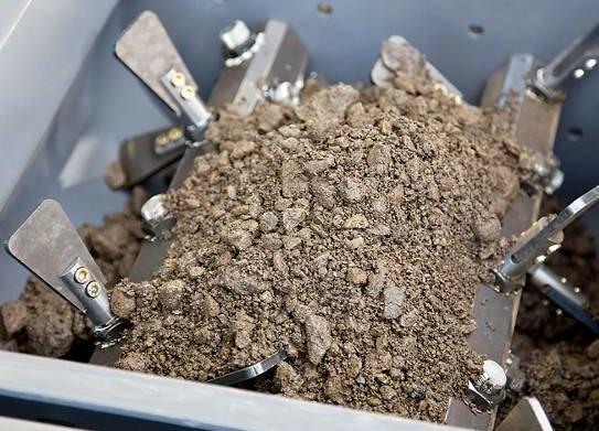

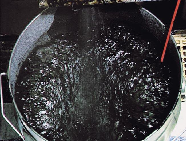
UCPRC-GL-2020-01 79
: Determining expansion ratio and halflife of asphalt binder.
Figure 5.6: Laboratory foaming unit coupled with a pugmill mixer.
Figure 5.7: Pugmill mixer used for all mix designs to replicate recycler mixing.
active are also recommended if relevant (i.e., roads where the asphalt concrete that is being recycled is relatively new or if there is significant recent patching or digouts along the project).
Indirect tensile strength (ITS) tests are more commonly used than penetration or performance grade tests for this purpose in foamed asphalt mix designs. Test are conducted on compacted and cured specimens with no recycling agent or active filler following the specimen preparation, curing, and soaking procedures in the CT-315 procedure. If the wet strength, with no recycling agent or active filler, exceeds 14.5 psi (100 kPa), then the asphalt in the recycled material may still be active and the foamed asphalt content may need to be adjusted based on the results of these tests to prevent early rutting in the recycled layer.
A flowchart summarizing the main steps in a foamed asphalt mix design is shown in Figure 5.11, at the end of the chapter.
5.4.3 Portland Cement (Full-Depth Recycling)
Until a Caltrans method for mix designs of cement-treated materials is published, follow the mix design procedure in LP-8-C in Appendix B. This mix design procedure is based on initial consumption of stabilizer (ICS, Figure 5.8) to identify a minimum starting cement content that will ensure a durable mix and an adequate unconfined compressive strength (Figure 5.9).
Durability testing is optional if project considerations warrant them (e.g., known freeze-thaw conditions). Coating and raveling tests, and tests on the existing asphalt binder discussed for emulsified and foamed asphalt are not relevant for portland cement mix designs.
Although Caltrans specifications for FDR-C projects currently require an unconfined compressive strength between 300 and 600 psi (2.1 and 4.1 MPa), it is recommended that a lower strength range of 300 to 450 psi (1.7 and 3.1 MPa) be targeted in the mix design to limit the likelihood of shrinkage cracking. This range is in line with the Portland Cement Association’s Guide to FullDepth Reclamation (FDR) with Cement (250 to 400 psi) (15) and with other state specifications such as Virginia’s.
A flowchart summarizing the main steps in a portland cement mix design is shown in Figure 5.12, at the end of the chapter.
80 UCPRC-GL-2020-01
The ICS and durability tests have not been widely practiced as part of mix designs for cementtreated materials in California in the past, although durability testing is recommended as part of the mix design in the Portland Cement Association’s guidance (15). These tests, and specifically the ICS test, are encouraged, especially for recycled layers that consist primarily of good quality materials (i.e., asphalt concrete, aggregate base layers, or old cement-treated layers) that will likely have relatively high unconfined compressive strengths at relatively low cement contents. Under these conditions, the recycled layer may be strong, but it may not be durable, which can lead to shrinkage and other types of cracking, crushing, and/or carbonation-related failures.
Initial Consumption of Stabilizer Test
The ICS test is based on ASTM D6276 [Standard Test Method for Using pH to Estimate the SoilLime Proportion Requirement for Soil Stabilization], which was originally developed for determining minimum lime contents in lime-treated soils. However, the method can also be used, with minor modification, to indicate an appropriate minimum starting cement content that will ensure a permanent stabilization reaction and result in a durable mix. These results must always be verified with strength and, where appropriate, durability tests.

A modified ICS test method is included in the LP-8-C test method in Appendix B. The key differences between the LP-8-C and ASTM D6276 methods include the following:
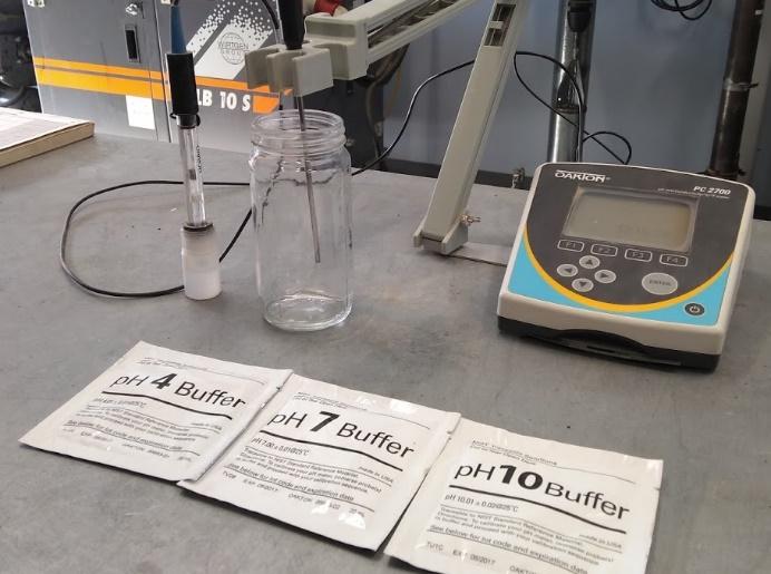
UCPRC-GL-2020-01 81
Figure 5.8: Initial consumption of stabilizer test.
Figure 5.9: Unconfined compressive strength test.
• The LP-8-C method is run on the material passing the 0.75 in. (19 mm) sieve rather than on the material passing the #40 (0.425 mm) sieve, which is specified in ASTM D6276.
• In the LP-8-C method, the choice of a starting stabilizer content is based on the amount of stabilizer required to achieve a constant pH rather than the amount of stabilizer required to achieve a pH of 12.4, which is specified in ASTM D6276
The starting cement content for FDR-C mix designs should be the initial consumption value plus one percent to ensure durability and to account for variations in spreading, mixing, and material properties.
Durability Tests
Two tests are commonly used to assess the durability of cement-treated materials:
• ASTM D559/559M (Standard Test Methods for Wetting and Drying Compacted Soil-Cement Mixtures). Follow this method for all climate regions in California.
• ASTM D560/560M (Standard Test Methods for Freezing and Thawing Compacted SoilCement Mixtures). Consider this method if freeze-thaw damage to pavements is common in the vicinity of the project (potentially in High Mountain and High Desert climate regions of California).
There is no published guidance in the United States on limits for the wet-dry durability test. Published international research recommends a maximum loss of 20 percent (21). This limit is suggested for California until locally derived limits can be established.
The Portland Cement Association recommends a maximum loss of 14 percent for the freeze-thaw durability test (15) This limit is also recommended for California.
5.5 Mix Design Approvals
Caltrans currently reviews and approves mix designs submitted by contractors, but does not verify mix designs with independent testing. Mix design approval should include, but not be limited to the following checks Example mix design approval checklists are provided in Appendix C.
• For all mix designs:
+ The mix design is signed by a professional civil or geotechnical engineer registered in the state of California.
+ The testing laboratory is certified according to Caltrans requirements and the certifications are current.
82 UCPRC-GL-2020-01
+ The samples were collected from the specified locations on the project.
+ The specified number of mix designs, based on variability along the project, have been completed.
+ The specified mix design procedures were followed and the listed tests were used
+ The combined material ratios are representative of the pavement design and the actual materials that will be recycled on the project.
+ The gradation(s) used match those in the specified mix design procedures.
+ There is no significant variation in results between replicate specimens
+ Specific gravities, maximum dry densities, optimum moisture contents, and air-void contents of the materials and specimens appear reasonable.
• For emulsified asphalt and foamed asphalt mix designs:
+ The binder content of the reclaimed asphalt pavement (RAP) used in the mix design is reported.
+ A satisfactory range of binder contents was tested.
+ The active filler content is based on a maximum ratio of 2.5:1 emulsified asphalt residue or foamed asphalt to active filler and the active filler content has not been increased above this ratio to meet the minimum strength/stability requirements.
+ The dry and wet strengths/stabilities and retained strength/stability meet the minimum specified requirements with reasonable safety margins.
+ The strength/stability test results are plotted against binder content and the selected binder content is shown on the plot.
• For emulsified asphalt mix designs:
+ The results of tests on the emulsion (i.e., sieve test, residue by evaporation, penetration, ductility, and creep stiffness) all meet the specified requirements.
+ The raveling test results meet the specified minimum requirements.
+ The RAP coating test results meet the specified minimum requirements.
• For foamed asphalt mix designs:
+ The performance grade of the binder used is appropriate.
+ A satisfactory range of binder temperatures and foaming water contents were tested to determine the foaming properties.
+ The foaming properties (expansion ratio and half-life) of the asphalt binder meet the minimum specified requirements and take expected project temperature conditions into consideration.
+ If required in the project specifications, the raveling test results are reported and the results appear reasonable.
• For portland cement mix designs:
+ A constant pH was achieved in the initial consumption of stabilizer (ICS) test.
UCPRC-GL-2020-01 83
+ The ICS plus 1 percent cement was used as the starting cement content and at least two other cement contents above this starting content were tested.
+ The UCS test results are plotted against cement content and the selected cement content is shown on the plot.
+ The selected cement content meets or is higher than the ICS plus 1 percent requirement and results in an unconfined compressive strength (UCS) within the specified range (preferably between 300 and 450 psi [2.1 and 3.1 MPa]).
+ The strengths are consistent with the cement content. Higher cement contents (e.g., more than 4 percent) should not give unrealistically low strengths and low cement contents (e.g., 2 to 4 percent) should not give unrealistically high strengths.
84 UCPRC-GL-2020-01
Sample representative materials
Test PG of extracted RAP binder
Mix Design for In-Place Recycling with Emulsified
(EA) (Caltrans Test CT-315 ) Yes
Is RAP primarily new or mostly new patches?
No
Check penetration of extracted binder, or ITS of RAP with no recycling agent
Crush bound materials to representative grading
Dry materials to constant weight at 60ºC
Fractionate and reconstitute to target gradation
Determine optimum moisture content and max dry density
Is active filler type specified?
Determine optimum emulsified asphalt content
Determine raveling resistance
Does optimum EA content pass raveling target?
Determine active filler type
1Select 4 binder contents
2 Compact specimens
3 Cure specimens for 72 hours
4 Dry cure 3 specimens for additional 24 hours
5 Moisture condition 3 specimens for 24 hours
6 Test Marshall stability (and indirect tensile strength if required )
7 Calculate retained stability (and strength)
8 Determine air void content
Increase EA content to meet target resistance
Check coating of aggregate
Determine job mix formula
Report results
UCPRC-GL-2020-01 85
Figure 5.10: Simplified flowchart summarizing main steps in an emulsified asphalt mix design.
Asphalt
Yes No
No Yes
Sample representative materials
Test PG of extracted RAP binder
Crush bound materials to representative grading
Dry materials to constant weight at 60ºC
Fractionate and reconstitute to target gradation
Determine optimum foaming temperature and water content
Determine optimum moisture content and max dry density
Is active filler type specified?
Yes
Determine optimum foamed asphalt content
Does optimum FA content pass raveling target?
No Yes
Is RAP primarily new or mostly new patches?
Mix Design for In-Place Recycling with Foamed Asphalt (FA ) (Caltrans Test CT-313 [FDR] and CT -315 [PDR]) Yes No
Check ITS of RAP with no recycling agent
Determine active filler type
1Select 4 binder contents
2 Compact specimens
3 Cure specimens for 72 hours
4 Dry cure 3 specimens for additional 24 hours
5 Moisture condition 3 specimens for 24 hours
6 Test indirect tensile strength
7 Calculate retained strength
8 Determine air void content
Increase FA content to meet target resistance
Report results
86 UCPRC-GL-2020-01
Figure 5.11: Simplified flowchart summarizing main steps in a foamed asphalt mix design.
Determine job mix formula No
Determine raveling resistance (recommended)
Sample representative materials
Crush bound materials to representative grading
Dry materials to constant weight at 60ºC
Fractionate and reconstitute to target gradation
Determine initial consumption of stabilizer (ICS test)
Determine optimum moisture content and max dry density
Determine optimum cement content
Mix Design for In-Place Recycling with Portland Cement (Caltrans Lab Procedure LP-8-C)
Is durability a concern? Determine durability
Determine job mix formula
Report results
1Select 3 cement contents (e.g., ICS +1, 2 & 3%)
2 Compact specimens
3 Cure specimens for 7 days
4 Test unconfined compressive strength
UCPRC-GL-2020-01 87
Figure 5.12: Simplified flowchart summarizing main steps in a portland cement mix design.
No
Yes
88 UCPRC-GL-2020-01 Blank page
6. CONSTRUCTION
6.1 Introduction
As with any road construction project, the construction procedures and quality of the work on in-place recycling projects are both critical to ensuring that the final pavement will perform satisfactorily over its design life. The recycling of layers and mixing of the recycling agent/stabilizer are intricate processes that require the correct equipment, an experienced crew, and careful logistical planning. It is important to remember that in-place recycling is different than the construction of unbound layers and the placement of asphalt concrete, and it therefore requires different supervision and inspection skills. This chapter highlights the key issues pertaining to specification enforcement and to the oversight of procedures that should be considered when contractors rehabilitate roads using in-place recycling processes. Deviations from accepted procedures may influence short- and long-term performance In each section below, items relevant to all recycling process are covered first, then followed by items specific to individual recycling strategies, if appropriate.
6.2 Specification Requirements
Specifications for full-depth in-place recycling (FDR) are covered in Section 30 of the Caltrans Standard Specifications. As of this writing, partial-depth (PDR) and cold central plant recycling (CCPR) are covered by non-standard special provisions (nSSPs). Specifications and nSSPs are updated at regular intervals and the latest versions should be referred to when reading this guide given that the updated specification language may be different to the information provided in the latest version of this guide. Key procedures covered in the specifications and special provisions that Caltrans site personnel need to beware of include the following:
• All in-place recycling
+ Review and approval of the quality control plan
+ Review and acceptance of the mix design/job mix formula (see Chapter 5)
+ Review and approval of the contingency plan
+ Review and approval of the traffic control plan
+ Participation in the preconstruction meeting
+ Approval of the equipment fleet with spot checks of pipe connections and inspections for leaks
UCPRC-GL-2020-01 89
+ Checks of ambient and pavement temperatures
+ Approval of the test strip and rolling patterns
+ Checks on active filler and stabilizer spread rate and uniformity
+ Checks on the uniform dispersion of the recycling agent or stabilizer, the recycling operation, and the consistency of the recycled material, including moisture content
+ Checks on recycling depth, overlaps, and joints
+ Checks on material spreading, compaction procedures, rolling patterns, the quality of the compacted layer, and the compaction and relative densities achieved
+ Checks of final grade, width, thickness, surface integrity, and smoothness of the compacted recycled layer
+ Assessment of curing seal and sand applications and temporary striping prior to opening to traffic
+ Checks on surface condition prior to placement of the asphalt concrete wearing course
+ Submittal of the daily quality control report, including general information, production rates and quantities, measurements and test results, and compliance certificates
+ Submittal of samples
• Additional specifications relevant to CCPR
+ Testing of gradations after crushing
+ Checks on the consistency of the recycled material, including moisture content, and the uniform dispersion of the recycling agent or stabilizer
+ Length of time that material is stockpiled
• Additional specifications relevant to foamed asphalt
+ Checks on asphalt binder temperature on tankers. Note that recycling equipment can maintain asphalt binder at the required temperature, but it is not equipped to heat it to that temperature.
+ Checks on foam half-life and expansion ratio
• Additional specifications relevant to recycling with emulsified asphalt
+ Checks on supplemental compaction of the recycled layer
• Additional specifications relevant to FDR with portland cement
+ Checks that prepulverized layers are milled to a depth 0.2 ft less than the design recycle depth, and shaped and compacted prior to spreading and mixing of cement to the full design depth
+ Checks on shrinkage crack mitigation (microcracking)
6.3 Key Issues for Successful Construction of In-Place Recycled Pavements
Key issues for the successful construction of in-place and cold central plant recycled pavements are discussed briefly below. Some may not be called out specifically in the specifications, but
90 UCPRC-GL-2020-01
engineers and superintendents need to be aware of them and to check on them during construction. Note that many of the potential problems discussed below are not commonly observed on projects with experienced recycling contractors, but it is important for agency staff to be aware of them.
• Contractor experience (Section 6.3.1)
• Traffic accommodation (Section 6.3.2)
• Premilling (Section 6.3.3)
• Importing new material (Section 6.3.4)
• Equipment inventory (Section 6.3.5)
• Recycling train crew responsibilities (Section 6.3.6)
• Daily recycling train setup (Section 0)
• Test strip (Section 6.3.8)
• Prepulverization (Section 6.3.9)
• Weather conditions (Section 6.3.10)
• Recycling plan (Section 6.3.11)
• Active filler/powder stabilizer spreading (Section 6.3.12)
• Lateral joints (Section 6.3.13)
• Compaction moisture (Section 6.3.14)
• Material placement/spreading (Section )
• Primary compaction (Section 6.3.16)
• Final grades and intermediate and final compaction (Section 6.3.17)
• Quality control and quality assurance (Section 6.3.18)
• Curing (Section 6.3.19)
• Opening to traffic (Section 6.3.20)
• Shrinkage crack mitigation (microcracking) on FDR-C layers (Section 6.3.21)
• Surfacing (Section 6.3.22)
• Drainage (Section 6.3.23)
6.3.1 Contractor Experience
The in-place recycling component of rehabilitation projects is, in most instances, done by a recycling subcontractor. This subcontractor usually does the active filler spreading and operates the recycling train, which includes the subcontractors water truck, and if an asphalt recycling agent is used, an asphalt binder tanker. On PDR projects, compaction, curing seal application, sand spreading, and temporary striping are done by either the subcontractor or the prime contractor depending on the contract arrangement. On FDR projects, primary compaction is
UCPRC-GL-2020-01 91
often done by the subcontractor, with shaping, levelling, final compaction, curing seal application, sanding, and temporary striping done by the prime contractor. It is therefore important for prime contractors to be completely familiar with the recycling process before work begins, especially on the specific components that differ from those in conventional construction and rehabilitation that are detailed below. As with any construction project, the safety of workers and the public is very important and all crew members should be fully trained on all safety issues, especially in handling the high temperature asphalt binder in the case of foamed asphalt projects.
Agency staff should ensure that the roles and responsibilities of all parties are clear at the preconstruction meeting.
6.3.2 Traffic Accommodation
In-place recycling generally has less impact on traffic than most other rehabilitation or reconstruction options because of its often shorter construction periods and the smaller number of trucks removing old material and bringing in new material.
On two-lane roads, one lane is typically recycled at a time, allowing controlled traffic to use the remaining half of the road (Figure 6.1). The recycled layer (PDR and FDR) can usually be opened to traffic within a few hours after final compaction as long as speed limits are reduced to prevent raveling of the surface. Appropriate speed and traffic control measures must be implemented by the contractor.
On multi-lane highways with higher traffic volumes, construction is usually done behind cones or a k-rail, and the road is usually only opened to traffic once the asphalt concrete has been placed and striping has been completed.
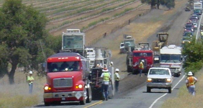
92 UCPRC-GL-2020-01
Figure 6.1: Pilot car traffic control on FDR project.
6.3.3 Premilling
Premilling and removal of the recycled asphalt pavement (RAP) may be required if the existing asphalt concrete is too thick (i.e., typically, thicker than 0.85 ft [250 mm]), or if precise surface levels and/or crossfall need to be maintained (e.g., in urban areas). Premilling and/or excavation of shoulders, if these are included in the recycle, may also be required. Standard milling equipment and procedures are used and it must be completed ahead of recycling operations and before the active filler is spread (Figure 6.2 and Figure 6.3) If necessary, with appropriate traffic control and information signs set up, traffic can drive on the pre-milled surface after brooming. Note that premilling should not be confused with prepulverization, which is discussed in Section 6.3.9.
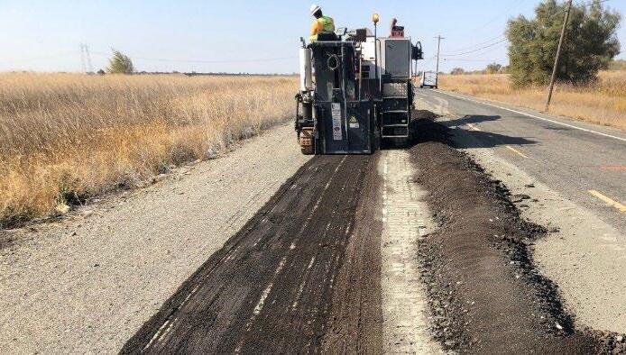
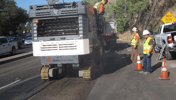
Note that aggregate layers will also need to be excavated to the recycling depth and removed.
6.3.4 Importing New Material
Additional aggregate base, RAP, or other recycled material may be called for in the rehabilitation design to correct grades, increase layer thickness, and/or to improve the bearing capacity of the pavement structure. This additional material must be included in the mix design in the correct proportions if it will be part of the recycled layer.
Note that crushed recycled portland cement concrete typically contains some unhydrated cement that will hydrate during mixing and compaction. On FDR-C projects, this can lead to additional available cement than can lead to higher than expected unconfined compressive strengths that may exceed the specified limits for FDR-C materials.
UCPRC-GL-2020-01 93
Figure 6.2: Premilling to maintain crossfall prior to PDR.
Figure 6.3: Premilling to include shoulders in a PDR project.
Additional aggregates that meet the specified requirements should be spread to the required thickness on top of the existing road surface, shaped to the required cross-slope, watered, and then compacted to the specified density. This operation should be completed before recycling operations begin (Figure 6.4 and Figure 6.5). The compacted surface can be trafficked at low speeds for short periods if necessary (e.g., for local access), provided that the surface is watered to prevent raveling and to control dust.


Supplemental fines used to improve gradation should be spread on the pavement ahead of the recycling train using a process similar to that used for spreading active fillers and powder stabilizers. On CCPR projects, supplemental fines should be blended with the crushed material prior to processing. Note that some cold central plants can accommodate blending of materials in the hopper.
6.3.5 Equipment Inventory
Rehabilitation or reconstruction using in-place or cold central plant recycling requires specialized equipment in addition to that used for the rehabilitation or reconstruction of conventional aggregate and asphalt concrete pavement layers. The recycling trains and, where used, cold central plant, are fundamental components of the equipment inventory on in-place recycling projects and must be calibrated and operating correctly, and where required, must have current Material Plant Quality Program (MPQP) certificates. The remaining equipment requirements are similar to those for conventional asphalt concrete construction, in the case of PDR, and aggregate base course construction, in the case of FDR.
• Partial-depth recycling trains PDR trains are either single- or multi-unit (Figure 6.6 and Figure 6.7).
94 UCPRC-GL-2020-01
Figure 6.4: Distressed road prior to addition of new layer.
Figure 6.5: Adding new layer for structural improvement prior to recycling.
+ On single-unit trains, a lane-width cutting head mills the pavement to the required depth and cross-slope, sizes the material, injects the recycling agent and compaction water (both fed from separate tankers pushed by the recycler), and mixes them with the milled material. Injection of the recycling agents and water are volumetrically controlled by systems that adjust the quantities based on forward speed and cutting depth. These trains do not include screening and crushing units, but are able to achieve the desired gradation by operating the cutting head in a down-cutting mode, by controlling the forward speed of the machine, and with the use of pressure and breaker bars. The recycled material can be paved through a screed attached to the recycler, by beltfeeding the recycled material into a following paver, or by windrowing the material for pickup and loading into a paver. Single-unit trains have the advantage of shorter length, which allows for greater maneuverability, but a disadvantage of less control of gradation, especially on pavements with severe alligator cracking where the blocks are loose and difficult to mill/grind to a satisfactory gradation
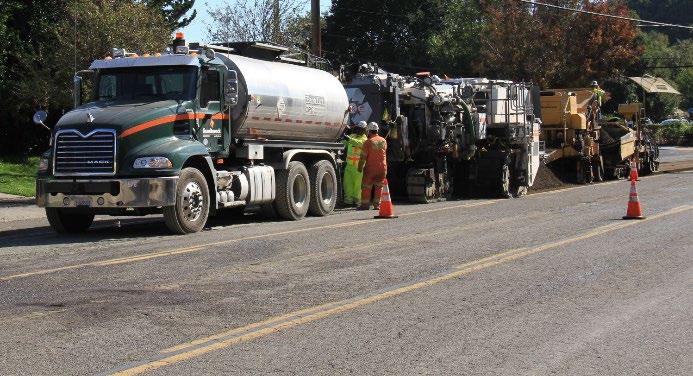
+ Multi-unit trains typically consist of a lane-width cold planing machine followed by a trailer with a screening unit, a crusher, and a pugmill mixer. Oversized material retained on the screen is crushed before being fed into the pugmill, which contains the asphalt recycling agent and water injection systems. These systems are controlled by scales on the belts that feed the pugmill. Processed material is either belt-fed into the paver, or windrowed for the pickup machine and paver combination. Multi-unit trains have the advantage of better gradation control and more accurate proportioning, which is based on the actual weight of the recycled material, but the disadvantage of decreased maneuverability due to their greater length.
+ Calibration certificates for metering systems must be available for all recyclers on the project.
• Full-depth recycling trains. FDR trains are either wheel-driven (up-cut, Figure 6.8) or trackdriven (down-cut, Figure 6.9) single-unit recyclers.
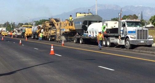
UCPRC-GL-2020-01 95
Figure 6.6: Single-unit PDR recycling train.
Figure 6.7: Multi-unit PDR recycling train.
+ Cutting head widths on wheel-driven recyclers vary, with 8 ft to 10 ft (2.4 m to 3.0 m) being the most common. Some newer track-driven recyclers can now do full lane width (and wider if segmented drum systems are used) FDR to a depth of 12 in. (300 mm), which minimizes the number of passes required. Track-driven FDR trains operate in the same way as the single unit PDR trains described above.
+ Wheel- and track-driven trains have the same or similar recycling agent and water injection systems, which are adjusted by automated control systems based on forward speed and cutting depth. Recycling agents and compaction water are fed from separate tankers pushed by the recycler. The desired gradation and mixing are controlled by the forward speed of the machine, and with the use of pressure and breaker bars.
+ When wheel-driven trains are used, the recycled material is left in place and it needs to be compacted in a specific way (described in Section 6.3.16) to ensure that differential compaction caused by the recycler tires does not impact later performance. Given that the recycled material is not laid with a paver, the cutting depth, grade, and material gradation and consistency are more difficult to monitor than with track-driven equipment.

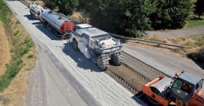
+ Calibration certificates for metering systems must be available for all recyclers on the project.
• Cold central plant recycling units. Cold central plants can either be specifically designed for the purpose (Figure 6.10), or be a stationary setup of the screening/crushing/pugmill part of a multi-unit PDR train described above (Figure 6.11). Central plants include asphalt binder and water supplies, and silos for the active filler or powder stabilizers. Millings from the project or from RAP piles are crushed on site (usually in an impact crusher) and screened to the required grading before being fed into the central plant. The materials are mixed along with the injected asphalt recycling agent, active filler, and compaction water in a twin-shaft pugmill. Injection systems are controlled by scales on the belt feeds. The
96 UCPRC-GL-2020-01
Figure 6.8: Wheel-driven FDR recycling train. Figure 6.9: Track-driven recycling train for PDR and FDR (down to 12 in. [300 mm]).
processed material exits the pugmill onto a belt that carries it directly into a waiting truck (which may have just transported millings from the project) or onto a temporary stockpile.

+ CCPR materials should not be stockpiled for long periods ahead of placement. The recycled materials must be placed and compacted within two hours of the start of mixing to ensure that target strengths and stiffnesses are achieved before emulsified asphalts start to break and/or the active filler/cementitious stabilizers have set up.
• Active filler/powder stabilizer and supplemental fines (Figure 6.12). Active filler, powder stabilizers, and supplemental fines (if used) need to be spread accurately and evenly ahead of the recycling train. Active fillers in slurry form are currently not considered in the Caltrans specifications. Note that most spreaders cannot accurately spread active filler contents of less than about 0.92 lb/ft2 (4.5 kg/m2). A spread rate of 1 percent active filler on a PDR project with a recycle depth of 0.33 ft (100 mm) equates to about 0.5 lb/ft2. Site calibration with trays is therefore especially important for active filler spreading where application rates usually do not exceed 1 percent (discussed in Section 6.3.12).

+ Most wheel-driven full-depth recyclers are configured to mix material primarily in the vertical plane (i.e., they do not mix material appreciably in the horizontal and longitudinal plane), making accurate stabilizer and active filler spreading an important factor to prevent isolated areas of very high strength and stiffness.
+ The application of powder stabilizers as a slurry at the mixing moisture content through full-depth recyclers is possible, but not commonly used in California, and currently not permitted in Caltrans specifications Although this can eliminate some of the problems associated with spreading dry powder (discussed in Section 6.3.12), it also reduces the ability to adjust moisture contents in wetter or dryer areas.
UCPRC-GL-2020-01 97
Figure 6.10: Cold central plant. Figure 6.11: Cold central plant using processing unit from a multi-unit recycling train.
• Pavers
+ Conventional asphalt pavers are used to place the recycled material on PDR and CCPR projects, and FDR projects with track-driven recyclers. Larger pavers will be required on FDR projects and/or if shoulder widening is part of the project.


• Rollers
+ On PDR projects, compaction is usually achieved with the same combination of rollers used on asphalt concrete layers (i.e., breakdown [Figure 6.13], pneumatic-tired [Figure 6.14], and finishing). Roller weights should be selected based on layer thickness. Note that project specifications may call for intelligent compaction of PDR layers.
+ On FDR projects, primary compaction is achieved with vibratory or segmented padfoot rollers (Figure 6.15 and Figure 6.16). Roller weights should be selected based on layer thickness. Examples of roller weights are provided in Table 6.1 Care must be taken to ensure that punching of the recycled material into the subgrade and/or pumping of fines from the subgrade into the recycled layer does not occur when heavier rollers (more than 18 tons) are used. Blades on padfoot rollers are useful for spreading material into the padfoot impressions on reverse passes to help the operator check on progress (i.e., primary compaction is typically achieved when impressions are no longer left by the pads). Final compaction is achieved with a combination of smooth-drum and pneumatictired rollers.
98 UCPRC-GL-2020-01
Figure 6.12: Active filler/stabilizer spreader.
Figure 6.13: Steel breakdown roller on a PDR layer.
Figure 6.14: Pneumatic-tired roller on a PDR layer.
a Care should be taken to ensure that punching of the recycled material into the subgrade or pumping
fines into the recycled layer does not occur when heavy rollers are used.
+ On CCPR projects, roller choice will depend on layer type and thickness. Thicker, lower layers (i.e., thicker than 0.4 ft. [125 mm]) are typically compacted as described for FDR layers, while thinner, upper layers are typically compacted as described for PDR layers. Subgrade stabilization as part of CCPR projects is typically compacted as described for FDR projects.
+ Regardless of project type, the weights of the individual rollers must be selected based on the thickness of the recycled layer. The specified density must be achievable throughout the thickness of the recycled layer. Smooth-drum rollers must have functional water sprays.
• Grader. Standard construction graders are used for final shaping and leveling on FDR projects.

• Water tankers. A dedicated second water tanker is usually made available for refilling the water tanker in the recycling train. Additional standard water tankers are used on FDR projects for correcting moisture content after primary compaction with the padfoot roller has been completed (i.e., during final shaping, leveling, and compaction), as well as for temporary dust control, limiting raveling, and curing in the period between completion of the recycled layer and spraying the curing seal. Although emulsified asphalt curing seals are more effective, water tankers may also be used on occasion for curing FDR-C layers.
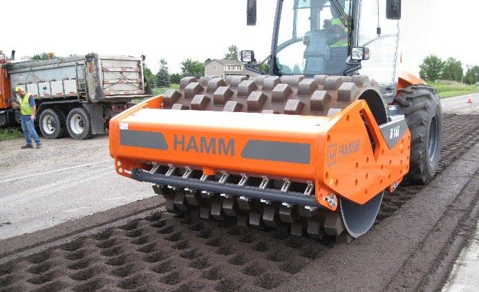
UCPRC-GL-2020-01 99
Figure 6.15: Vibratory padfoot roller on an FDR-FA layer.
Figure 6.16: Segmented padfoot roller on an FDR-C layer.
Compacted Layer Thickness (ft.) Compacted Layer Thickness (in.) Compacted Layer Thickness (mm) Static Weight (tons) < 0.50 < 6 < 150 ≥ 12 0.50 – 0.65 6 – 8 150 – 200 ≥ 15 0.65 – 0.80 8 – 10 200 – 250 ≥ 18 0.8 – 1.0 10 – 12 250 – 300 ≥ 20a > 1.0 > 12 > 300 ≥ 25a
Table 6.1: Example Primary Roller Weights for Different Layer Thicknesses
of the subgrade
• Loader. A loader is used for moving excess materials from the roadway and clearing aggregate and asphalt concrete spills from side drains and culvert openings.
• Mechanical broom. This is used to sweep loose material from the surface prior to applying the curing seal and sand cover and prior to placing the asphalt concrete surface layer(s).

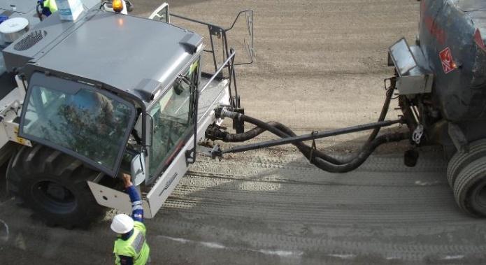
6.3.6 Recycling Train Crew Responsibilities
The recycling train crew must understand and be able to fulfill their responsibilities, which include but are not necessarily limited to:
• Checking for marked utilities, power lines, culverts, overhanging branches, etc., that may influence the recycling train.
• Checking that push/tow bars that connect the recycler to the recycling agent and/or water tankers are correctly installed and that the feed hoses are attached to prevent them (Figure 6.17) dragging along the road surface (Figure 6.18). Dragging hoses can redistribute active filler or stabilizer, resulting in areas with too little additive where the hose has dragged it away and too much additive where the hose deposits it (Figure 6.19). This can result in localized areas of very high additive content, especially on FDR projects, that can lead to localized early reflected shrinkage cracks (Figure 6.20).
• Checking that couplings between the tankers and recycler are tight with no leaks, and that there are no leaks or spills during tanker changes (Figure 6.21). These can lead to soft spots being left in the pavement (Figure 6.22) that may form localized depressions or potholes at a later date, especially if the layer is paved soon after recycling (Figure 6.23).
• Checking that the recycler drum is correctly zeroed on the road surface to ensure that consistent cutting depths at the required grade are achieved across the lane.
• Checking that recycling cutting drums are completely removed from the pavement layer when the machines are stopped but idling, to prevent localized areas of segregation caused by repeated turning of the drum (Figure 6.24).
100 UCPRC-GL-2020-01
Figure 6.17: Correct use of push bar with hoses attached.
Figure 6.18: Recycler with no push bar and hose dragging cement stabilizer (FDR-C).
• Checking that powder stabilizers or active fillers are spread evenly and consistently at the specified rate for a suitable distance ahead of the recycling train, while ensuring that spread rate is not affected by wind or passing traffic (discussed in Section 6.3.12).
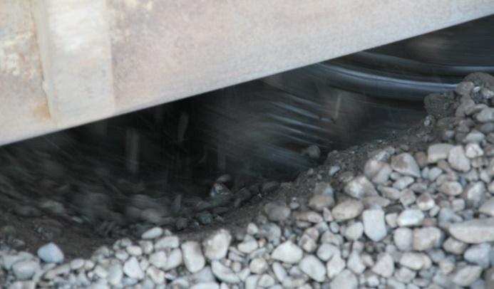
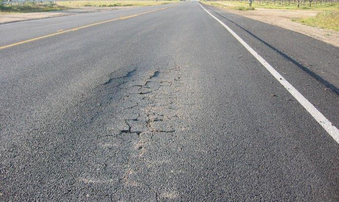


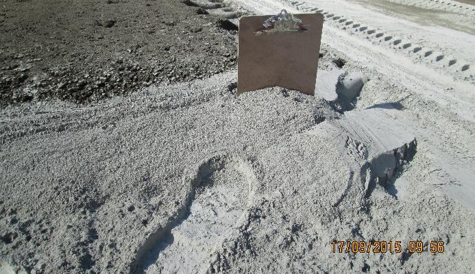
• Marking guides to ensure that adequate overlaps are included in each recycling pass (discussed in Section 6.3.11).
• On projects where track-driven single-unit PDR and FDR trains, and wheel-driven FDR trains are used:
UCPRC-GL-2020-01 101
Figure 6.19: Accumulated cement dragged by hose at end of recycling run (FDR-C).
Figure 6.20: Early shrinkage cracks in area of accumulated cement (FDR-C).
Figure 6.21: Water leak during tanker change (FDR).
Figure 6.22: Wet area caused by water leaks during tanker change (FDR).
Figure 6.23: Localized early failure resulting from a wet area (FDR).
Figure 6.24: Localized segregation caused by idling recycler drum (FDR).
+ Checking that an appropriate speed of advance is maintained to ensure an optimal gradation and consistent mixing of the material and additives (typically between 18 and 33 ft/min [7.0 and 9.0 m/min]).
• On projects using asphalt recycling agents:

+ Checking the delivery paperwork for each tanker to ensure that the specified emulsified asphalt/correct binder grade has been delivered and that the source has not been changed.
+ Checking that binder temperatures in the tankers are within the acceptable range. Note that both emulsified and foamed asphalt must be kept within specified temperature ranges.
• On foamed asphalt projects
+ Checking that asphalt binder temperature in the tanker is within an appropriate range prior to connecting to the recycler. This temperature should be determined from a sample collected in a bucket from the outlet or from the hatch on top of the tank. Tank thermometers, if installed, should not be trusted. Binder below the specified temperatures (i.e., mix-design temperature) or above 375°F (190°C) must be returned to the refinery.
+ Checking binder foaming characteristics when each new tanker load is connected to the recycler or central plant (Figure 6.25). Recyclers and central plants have a dedicated, accessible foaming nozzle for these checks (Figure 6.26).
• Ensuring that an experienced technician is always present behind the recycler to monitor all operations and ensure that immediate appropriate actions are taken to correct any problems. This is important because of the variability in materials, moisture content, and layer thickness in the old pavement. Actions include communication with the recycler operator to adjust machine settings, stopping the recycling train to correct problems,
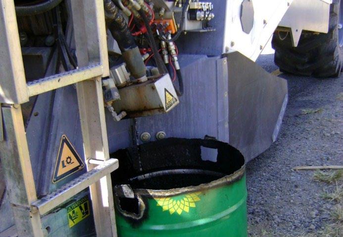
102 UCPRC-GL-2020-01
Figure 6.25: Checking binder foaming characteristics after tanker change.
Figure 6.26: Nozzle for checking binder foaming characteristics.
and/or reworking sections of the road. Responsibilities of this technician include, but are not limited to the following:
+ Ensuring that appropriate safety procedures are followed during recycling, especially during the change-over of asphalt binder tankers, and when work is conducted between the recycler, tankers, and rollers.
+ Checking that cut depth on both sides of the recycler meets the design requirements for layer thickness and crossfall. Feedback on the depth should be provided to the recycler operator for appropriate adjustments. If the recycling depth is less than the specified depth, the recycling train must be stopped and the section reworked to the correct depth. New recycling agent/active filler or stabilizer should not be added during the rework, although the compaction moisture content may need to be supplemented.
On PDR projects, and FDR projects with track-driven recyclers, depth is checked by measuring the depth on both sides of the cut between the recycler and the paver (Figure 6.27).
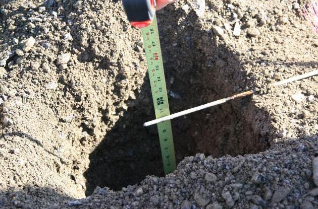
On FDR projects, depth can be measured across the recycled material using a string line and T-bar; or by using a T-bar or digging a hole on either side of the recycled path (Figure 6.28) and measuring the depth against a reference point (e.g., the existing pavement) (Figure 6.29 and Figure 6.30). Measurements should be taken at least every 300 ft (100 m) Where feasible, digging a furrow across the full recycled width with a shovel or backhoe every 1,500 ft (500 m) is useful for assessing recycling depth and material consistency throughout the layer. Excavated material must be replaced back into any holes and trenches before primary compaction starts.

UCPRC-GL-2020-01 103
Figure 6.27: Checking recycling depth on a PDR project.
Figure 6.28: Checking recycling depth in a hole on an FDR project.
+ Visually checking that mixing fluid contents in the recycled layer are within an appropriate range and adjusted to account for variations in in-situ moisture content in the road. Fluid content can be water or a combination of recycling agent (e.g., emulsified asphalt) and water. A simple “squeeze test” provides a good indication of the fluid content (a handful of material, when squeezed, should not exude water [too wet], or crumble [too dry] when released [Figure 6.31]).
+ Checking recycle overlaps at least every 300 ft (100 m) at the same time as the recycling depth checks. If a strip of unrecycled material is encountered between two recycling paths, the recycling trains must be stopped and the strip reworked.
+ Checking for high fines contents and/or the presence of clay. Small, soft balls of fine material in the mix that feel “spongy” when squeezed can be an indication of this.


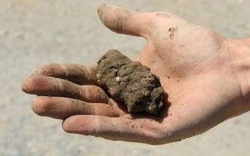
+ Checking that all nozzles in the spray bars (water and asphalt) are always functioning.
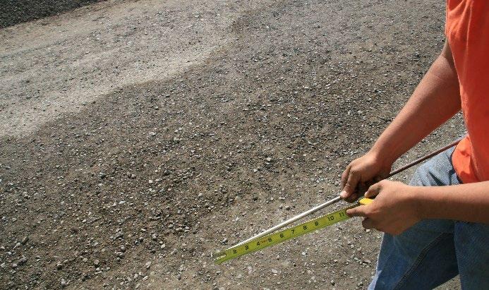

+ Checking that material characteristics, material consistency, and gradation are acceptable, and giving suggested forward speed or drum speed adjustments to the recycler operator when appropriate (Figure 6.32 through Figure 6.35). There should be no particles larger than the specified maximum aggregate size.
+ On CCPR projects, checking that material has not been stockpiled longer than the specified allowable period and that the material is still workable. Key issues to check include whether the active filler or stabilizer has set up (hard lumps of agglomerated
104 UCPRC-GL-2020-01
Figure 6.29: Checking recycling depth using a Tbar on an FDR project.
Figure 6.30: Measuring recycling depth on the Tbar (FDR).
[a] [b] [c]
Figure 6.31: Squeeze test for assessing moisture content ([a] good, [b] too dry, [c] too wet).
aggregate), and whether the material still appears to be workable (the squeeze test can be completed and the resulting ball easily broken up into constituent parts). On emulsified asphalt projects, additional checks will include whether the emulsion has broken (material is black instead of brown).


consistency and gradation (FDR).
(Note that working between the recycler and a towed vehicle is not recommended for safety reasons).

+ Checking that non-aggregate materials such as raised pavement markers, cat eye road studs, fabric (Figure 6.36), and/or crack seal (Figure 6.37) are either satisfactorily milled and will not affect performance of the recycled layer, or are removed from the recycled material. Note that pavement markers and studs should have been removed from the road surface prior to recycling.
+ Checking that primary rollers (steel breakdown roller on PDR and padfoot on FDR) are never more than 300 ft (≈100 m) behind the recycling train, and stopping the recycling train if these rollers fall too far behind. Allowing rollers to fall behind the recycling operation can result in the material drying out before primary compaction is complete. Delays in completing compaction can also influence active filler and stabilizer reactions.
+ Clearing markers in the material that overflows onto the adjacent pavement with a rake, shovel, or boot to indicate the edge of the recycle path (Figure 6.38). This assists roller
UCPRC-GL-2020-01 105
Figure 6.32: Good gradation and consistency behind the recycler on a PDR project.
Figure 6.33: Oversize material behind the recycler on an FDR project.
Figure 6.34: Sampling to check material
Figure 6.35: Checking material consistency and gradation (FDR).
operators in keeping the roller on the recycled material to prevent bridging (discussed in Section 6.3.16).
+ On projects with asphalt recycling agents:
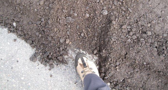
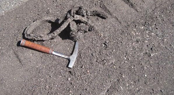
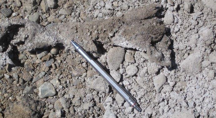
Checking for blocked nozzles. On FDR projects, this is often indicated by binder adhering to the recycler tires (Figure 6.39 through Figure 6.41). Alternatively, globules and stringers of asphalt in the recycled material are also indicators of the problem (Figure 6.42). Crews must notify the recycler operator and stop the recycling train if problems with the spray bars are apparent. Stringers or globules of asphalt recycling agent will result in localized areas of very high asphalt binder content, which can in turn lead to areas of localized deformation (Figure 6.43).
Using the squeeze test described above to assess asphalt binder dispersion. Large sticky spots of asphalt remaining on the hand after squeezing the material indicates poorly dispersed asphalt binder (Figure 6.44). On foamed asphalt projects, after squeezing, asphalt binder should show as tiny “pinpricks,” indicating good dispersion of the foam (Figure 6.45). If a sheen of water is left on the hand along with the pinpricks of binder, this usually indicates that the foaming water content is too high. Using the squeeze test to get an indication of the cohesiveness of the material. This is done by rolling the squeezed material into a ball, holding the ball between the thumb and index finger, and then applying gentle pressure on opposite sides. The ball
106 UCPRC-GL-2020-01
Figure 6.36: Fabric behind the recycler on an FDR project.
Figure 6.37: Crack seal behind the recycler on a PDR project.
Figure 6.38: Clearing marks in overflow material to guide roller operators.
should deform before falling apart. The face of the broken ball should be inspected for asphalt dispersion. The presence of asphalt globules indicates a poor mix.


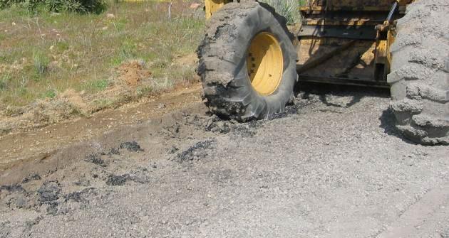
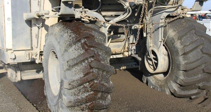
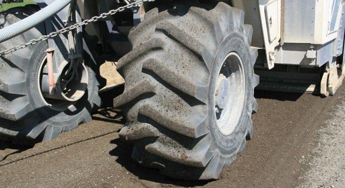
UCPRC-GL-2020-01 107
Figure 6.39: Normal tire condition when nozzles are functioning correctly (FDR).
Figure 6.40: Effect of problem nozzles on an FDREA project.
Figure 6.41: Effect of problem nozzles on an FDR-FA project.
Figure 6.42: Unfoamed binder in recycled material on an FDR-FA project.
Figure 6.43: Localized early rutting caused by nozzle problem in Figure 6.41.
Figure 6.44: Poorly dispersed asphalt recycling agent (nozzle problem).
Figure 6.45: Good dispersion of foamed asphalt.
“Pin pricks” of binder
+ On PDR projects:
Checking that the exposed layer in the cut between the recycler and the paver is intact and that there are no signs of distresses that will affect the completed pavement’s performance (discussed in Section 6.3.8).
+ On FDR projects
Checking that the color of the material immediately across the width of the recycled material behind the recycler is consistent, indicating that the machine is set up correctly. A gradual change in color across the width normally indicates that one end of the drum is lower than the other and that the milling teeth have probably penetrated into another layer. A lighter appearance on one side can indicate underapplication of water and/or asphalt recycling agent or stabilizer caused by the drum penetrating beyond the specified depth. A darker color can indicate an overapplication due to the drum not penetrating to the required depth. Foamed asphalt application consistency can also be checked with a temperature gun. A variation in the temperature across the recycled material immediately behind the recycler often indicates inconsistent binder application (i.e., higher temperatures indicate higher binder application rates).
+ On FDR-C projects
Checking that the cement is being mixed to the required depth by the recycler. This can be done during the normal recycling depth checks described above by digging a hole and spraying the sides with phenolphthalein. This pH indicator will turn crimson in contact with cement, clearly showing to what depth the cement has been mixed (Figure 6.46 and Figure 6.47).
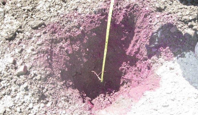
NOTE: The contractor crew and Caltrans supervisors working on and around the recycling train should be cautious at all times. Tanker changes, checking foam characteristics on foamed asphalt projects, and the monitoring of milling depth and recycled material behind the recycler are particularly dangerous exercises.

108 UCPRC-GL-2020-01
Figure 6.46: Checking recycling depth on an FDR-C project.
Figure 6.47: Checking cement mixing depth on an FDR-C project (note crimson color).
6.3.7 Daily Recycling Operations Setup
Apart from the standard start-up procedures specified in the equipment operating procedures and manuals, a number of preliminary checks should be completed before commencing operations each day. The procedures are quick and simple to carry out and should become routine practice at the start of every shift. Procedures include but are not necessarily limited to:
• All personnel on site participate in a daily safety briefing and understand each person’s roles and responsibilities. This is especially important if the recycling contractor is a subcontractor on the project.
• The recycler operator should confirm their familiarity with the day plan and that they have all relevant data including the recycling plan, overlaps, recycling agent contents, mixing moisture contents, and recycling depths. The recycler or central plant operator and walkbehind technician should check and confirm communication procedures.
• The operators of the active filler/stabilizer spreader, and, if used, the supplemental fines spreader, confirm their familiarity with the recycling plan, application rates, and required spread-distance ahead of the recycler, and are aware of the implications of overlaps and uneven spreading.
• Operators and drivers of all other ancillary machines and vehicles confirm that they have a clear understanding of their responsibilities and of what they are expected to do to ensure that the recycling operation is successful.
• Confirmation that daily maintenance and inspections have been completed on all machines and equipment to be used in the recycling operation.
• Confirmation that recycler settings (drum angle, drum speed, breaker bar and rear door pressure on single unit trains, etc.) are correct and that, where present, the rubber flap fitted to the base of the front door of the milling chamber has been lifted to prevent redistribution of the prespread active filler.
• Confirmation that all spray bar settings are correct, all nozzles are working, and that there are no blockages in the system.
• Confirmation that temperatures of the recycling agent, air, road surface, and spread stabilizer or active filler have been measured and are within specified ranges, or above specified minimums.
• Confirmation that sufficient quantities of recycling agent/stabilizer, active filler, and water are available or are scheduled for delivery to complete the day’s planned activities.
• Confirmation that feed pipes on recycling trains and central plants are correctly connected and leak-free, that valves are open, and that air has been bled from the system.
UCPRC-GL-2020-01 109
+ On foamed asphalt projects, checks should be made to ensure that there are no cold asphalt plugs in the hose connections on the tanker and/or recycler or central plant (Figure 6.48). These can damage the pumps.

• Confirmation that the recycler or central plant has been warmed up to the correct operating temperatures.
6.3.8 Test Strip
On the first production day, before full-scale operations begin, a single-lane test strip at least 1,500-ft (500 m) long should be constructed at the starting point of each project. This test strip provides the resident engineer and construction superintendent/inspector an opportunity to assess all aspects of the recycling part of the project, including many of the checks discussed in Sections 6.3.6 and 0 The test strip is constructed to check the following:
• The correct equipment is on site and in sound working condition, and that crews (contractor and subcontractor) are adequately trained and understand their roles and responsibilities
• The recycling train can produce and place an acceptable grading throughout the predetermined recycling depth; that no oversize chunks remain in the processed material; and that the recycling depth, measured against the adjacent unrecycled material on each side of the cut, meets the design requirements. The gradation should be checked against the mix-design grading (i.e., by pulverizing a short distance at the expected forward speed at the start of the test strip without the addition of any recycling agent/stabilizer). Adjustments should be assessed to determine minimum and maximum production speeds for the recycling train.
+ On wheel-driven and single-unit recyclers, grading can be changed by adjusting the recycling drum speed, the forward speed of the recycler, the position of the breaker bar in front of the milling and mixing chamber, and/or by adjusting the rear door of the mixing chamber.
110 UCPRC-GL-2020-01
Figure 6.48: Cold plug in the asphalt feed connection of a binder tanker.
+ On multi-unit trains, grading is controlled by a combination of forward speed and onboard screen and crusher settings.
+ On CCPR projects, the crushed material should be checked to ensure that it meets the required gradation, and that if supplemental fines are added, the gradation of the blended material is consistent.
• The moisture content of the in-situ material has been correctly estimated and that mixing and compaction moisture contents have been correctly calculated, and can be achieved by the recycler or central plant.
• The recycling agent delivery temperature is within specification, and on foamed asphalt projects, the expansion ratio and half-life of the binder meet or exceed the mix-design requirements.
• The stabilizer or active filler can be accurately and uniformly spread at the correct rate and that there is no significant overlap, which could lead to localized cracking due to higherthan-design stabilizer or active filler contents.
• The recycled material with recycling agent and active filler, or stabilizer, appears adequately processed prior to compaction; that there are no globules or stringers of asphalt in the mix. If wheel-driven recyclers are used, recycling agent or treated material should not adhere to the recycler tires.
• Samples for quality control and quality assurance testing are collected as per specification requirements. Typically, materials for testing are sampled between the recycler and paver, or from the paver on PDR and FDR projects with windrowed or belt-fed material, from behind the recycler on FDR projects, or from the belt feed on central plants. The materials are tested to check the properties on the test strip against those specified and/or determined during the mix design.
• The compaction equipment operators understand the differences between compacting recycled materials and asphalt concrete or natural aggregate base, know the correct procedures for compacting recycled layers (see Sections 6.3.16 and 6.3.17), and can keep up with the recycling train/paver.
• The correct bulking factor has been calculated and the following is undertaken to ensure that the design final levels can be achieved:
+ On PDR and FDR projects, the correct quantity of material is premilled from the surface, if required.
+ On FDR projects, the correct quantity of material is bladed from the road after primary compaction, if required.
+ On FDR-C projects, the correct quantity of material is bladed from the road after prepulverization, if required
• The specified density can be achieved at both the top and bottom of the recycled layer.
UCPRC-GL-2020-01 111
• The design surface finish and final levels can be achieved.
+ On FDR projects, the recycled layer can only be trimmed. Material may not be bladed back to add material on low spots as this will result in a “biscuit” layer that will delaminate or disintegrate when opened to traffic.
• The emulsified asphalt curing seal, sand, and temporary markings are correctly applied at the appropriate time.

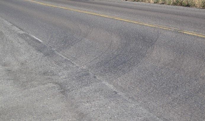
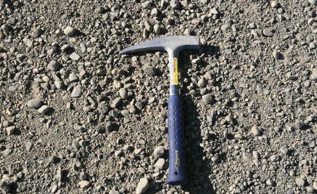

• The surface can be broomed if required without disintegration (Figure 6.49 and Figure 6.50) or raveling (Figure 6.51 and Figure 6.52).
112 UCPRC-GL-2020-01
Figure 6.49: Good quality PDR and FDR surfaces after final compaction.
Figure 6.50: Unacceptable PDR and FDR surfaces after final compaction.
Figure 6.51: Trafficked recycled layer with no raveling/scuffing from turning vehicles (PDR).
Figure 6.52: Trafficked recycled layer with severe raveling (patched) (PDR).
• On PDR projects:
+ The exposed old asphalt concrete layer in the cut behind the recycler is intact and there are no signs of distresses that will affect performance of the completed pavement. Distresses in the underlying layer such as thin layers of debonded material (Figure 6.53) or fatigue cracking (Figure 6.54) can be indications that the project investigation missed these distresses and/or that the choice of rehabilitation strategy was not appropriate.
The resident engineer must approve the test strip before the contractor can proceed with the project. If any project requirements cannot be met, the contractor will need to take the necessary steps to correct the problems before continuing with the project. Any adjustments to the process (e.g., change in asphalt binder content, active filler content, recycling depth, etc.) must be agreed on between the contractor and the resident engineer before proceeding or constructing a second test strip.
6.3.9 Prepulverization
Prepulverization, which should not be confused with premilling (Section 6.3.3), of the material prior to recycling (Figure 6.55) is not required on PDR projects. It should only be considered on FDR projects under the following conditions:
• Grade changes that require moving material longitudinally (to level undulations) or transversely (to widen the lane or add shoulders) along the project.
• Grade-height restrictions, which require removal of some of the existing material to accommodate for bulking (“fluffing”) of the recycled layer and the new asphalt concrete surface.

+ On some lower-volume roads where the existing pavement structure consists of relatively thick asphalt concrete layers over marginal base course material, prepulverization to the depth of the new recycled layer will mix the asphalt concrete and marginal base to form a homogenous material with improved properties. This
UCPRC-GL-2020-01 113
Figure 6.53: Thin, debonded layer on a PDR project.
Figure 6.54: Fatigue cracks in underlying layer on a PDR project.
Fatigue cracks
prepulverized layer can then be shaped and compacted, and the excess material scraped off, leaving an improved layer for treatment.
• On FDR-C projects, especially those with relatively high cement contents and/or recycle depths exceeding 0.75 ft (225 mm), to ensure satisfactory distribution and mixing of the cement and the compaction water.

Key issues to consider include, but are not necessarily limited to, the following:
• Multiple passes with a recycler can lead to breaking down of the aggregate and result in a finer gradation (and increased particle surface area) than the one used in the mix design. Consequently, strengths may be slightly lower and required compaction moisture contents may be slightly higher if multiple recycler passes are applied during a recycling project.
• Prepulverization results in considerable bulking of the material (Figure 6.56), making it very difficult for the recycler operator to know precisely where the bottom of the prepulverized layer is when setting up for subsequent passes To ensure that the correct thickness is recycled, it is important to complete the prepulverization and then shape and compact the road to the desired grade before starting the second phase, when recycling agents/stabilizers are added.
114 UCPRC-GL-2020-01
Figure 6.55: Prepulverization on an FDR project.
Figure 6.56: Bulking of material after prepulverization to a depth of 12 in. (300 mm).
• If lane or shoulder widening is part of the project, marginal or in-situ materials in the widening zone should be milled to the design depth and removed prior to the start of prepulverization to ensure that they are not mixed in with the better quality materials.
The following procedure for prepulverization is recommended:
1. If lane and/or shoulder widening is part of the project, marginal or in-situ materials should be milled and removed
2. Material is pre-pulverized to a depth of 0.2 ft. (60 mm) less than the design depth.
3. The pre-pulverized material is then spread, shaped, and compacted to the full design width, grade, and crossfall.
4. The active filler or stabilizer is spread on the compacted surface.
5. The material is recycled and mixed to the full design depth, accounting for any increase in grade height resulting from pre-pulverization (measured from a known reference point), and ensuring that there is no prepulverized, untreated material at the bottom of the recycled layer. Recycling and mixing should be done in a single pass with appropriate overlaps where required (see Section 6.3.11).
6. The recycled layer is compacted and shaped to the design grade and crossfall
6.3.10 Weather Conditions
In-place pavement recycling specifications state that recycling should not be started if rain is forecast within 24-hours. Minimum allowable ambient and pavement temperatures for recycling are listed in the specifications as follows:
• For PDR and FDR projects with asphalt recycling agents, ambient and road surface temperatures must both be higher than 50°F (10°C) before recycling can begin. If active filler has been spread, recycling should not start until the temperature of the active filler is higher than 50°F (10°C) (Figure 6.57).
+ On projects using foamed asphalt, note that effective dispersion of foamed asphalt in the material is reduced as the temperature of the material decreases. The recommended minimum expansion ratio is 10 and half-life is 8 seconds for recycling at temperatures between 50°F and 60°F (10°C and 15°C). At temperatures above 60°F (15°C), the recommended minimum expansion ratio and half-life can be relaxed to 8 and 6 seconds, respectively.
+ On FDR-C projects, ambient and road surface temperatures, and the temperature of the spread cement must all be higher than 40°F (4.5°C) before recycling can begin.
UCPRC-GL-2020-01 115
6.3.11 Recycling Plan
A number of factors influence the way a road will be recycled. The number of recycling passes will depend primarily on the type of recycling project, the road width, and the equipment used. The cross-slope influences the positioning of longitudinal joints between adjacent passes on FDR projects where wheel-driven recyclers are used. On PDR projects and on FDR projects recycled with a track-driven recycler, the recycling width is typically equal to the full lane width, and shoulder-widening can usually be accommodated by the paver in a single pass. Some newermodel track-driven recyclers have segmented drums that allow drum width to be reduced for working on narrower lanes, or extended for recycling a lane and shoulder together. On FDR projects recycled with wheel-driven recyclers, the recycling width is typically between 8 and 10 ft (2.4 and 3.0 m), which is narrower than standard lane widths. Overlap management is important on these projects. Considerations when preparing the recycling plan include but are not necessarily limited to the following:
• Steep gradients should be recycled by working downhill, where possible, to ensure that the required production speeds are maintained. Equipment operators should ensure that sufficient head is maintained over the outlet valves on the binder and water tankers, especially when working on gradients.
• Overlaps are required along the full length of each joint to achieve continuity between adjacent cuts. Centerline overlaps are typically between 0.5 and 1 ft. (150 mm and 300 mm) wide, with a width of 1 ft (300 mm) if the planned pass will overlap a pass constructed more than 12 hours earlier. Overlap widths within the lane will depend on the design width for recycling, and ensuring that marginal materials in the shoulder are not mixed in with the higher quality materials in the lane unless this was considered in the mix design.
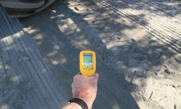
116 UCPRC-GL-2020-01
Figure 6.57: Active filler below specified starting temperature on an FDR-FA project.
46° F (6° C)
• Recycling plans must ensure that any joins or overlaps are positioned on the centerline of the road, the outside edge of the traveled lane, or in the middle of the lane. Joins or overlaps must never be in the traffic wheelpaths.
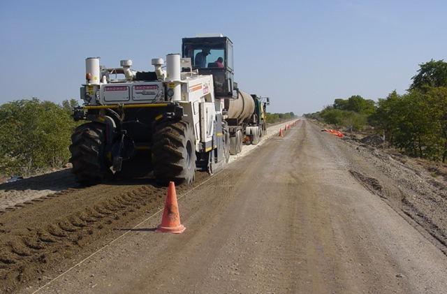
+ If no clear markers are present (e.g., lane markings) to guide operators, spray paint or string lines on the road should be used to assist the recycler operator and walk-behind technician with maintaining correct overlaps (Figure 6.58 and Figure 6.59).

• On projects where single-unit PDR and FDR trains and wheel-driven FDR trains are used:
+ The binder and water nozzle(s) in the overlap area must be switched off to prevent overapplication of binder and water.
+ Active filler must not be spread again in the overlap area if the overlap is recycled on the same day and within 8 hours of the original pass.
+ On FDR-C projects, cement must not be spread again in the overlap areas at any time.
• On FDR projects using wheel-driven recyclers:
+ The width of the recycled cut will usually be less than the road or lane width, so more than one pass will be required to recycle the full width; this will result in a series of longitudinal joints between adjacent passes. The location of these longitudinal joints must be either on the centerline or between the wheelpaths of any lane. Crowned roads should be treated in half-widths to maintain road shape and achieve a uniform depth of recycling across the crown. An example FDR recycle plan for a two-lane highway without shoulder-widening is shown in Figure 6.60
+ When planning the recycling operation, it should be noted that only the first cut will recycle virgin material over the full drum width, and thereafter, the effective width of all subsequent cuts will be reduced by the width of overlap.
+ The use of two recycling trains is preferable on most FDR projects using wheel-driven recyclers to limit time lost and address safety concerns when the recycling train is reversed on half-width projects, and to alleviate problems associated with overlaps and longitudinal joints (Figure 6.61).
UCPRC-GL-2020-01 117
Figure 6.58: Spray painting direction and overlap guides for the recycling train (FDR).
Figure 6.59: String line for direction and overlap guides for the recycling train (FDR).
6.3.12 Active Filler/Powder Stabilizer and Supplemental Fines Spreading
Stabilizers and active fillers, and supplemental fines when used, must be spread evenly on top of the road surface ahead of the recycling train. The following considerations are important:
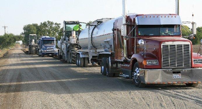
• Spread rates must be checked at least twice per day. This is best achieved by placing pans of known size and weight on the road surface ahead of the spreader and then weighing each pan after the spreader has passed (Figure 6.62 through Figure 6.66). The collected material must be spread back into the footprint of the tray after weighing. If the spread rates exceed the design application rate, the active filler/stabilizer or supplemental fines must be removed and reapplied at the correct rate.
• On FDR projects where wheel-driven or track-driven recyclers are used that spread the recycled material immediately behind the drum housing, consistent even spreading of the active filler/stabilizer to the same width as the recycling drum is critical since the lateral mixing ability of these recyclers is not as effective as the vertical mixing. These recyclers will not spread stabilizer and active fillers transversally or longitudinally on the project. + Spreading stabilizer, active filler, or supplemental fines in a strip that is narrower than the recycling drum (Figure 6.67) can lead to differential strength and stiffness across the
118 UCPRC-GL-2020-01
Figure 6.60: Example FDR plan for wheel-driven recyclers for a two-lane highway.
Figure 6.61: Tandem FDR train.
2.5 ft. overlap 3.0 ft. overlap Lane width (12 ft.) Recycle width (13 ft.) 0.5 ft. overlap Centerline Wheel Path Wheel Path Wheel Path Wheel Path Cut #1 Cut #2 Cut #4 Cut #3
recycled lane, which could lead to early corresponding longitudinal cracks and other distresses. Figure 6.68 shows a plot of stiffness measured with a light weight deflectometer (LWD) and soil stiffness gauge (SSG) on an FDR-FA project where the active filler was spread in a narrower width than the recycler drum. The stiffness of the compacted layer inside the spreader width was about 60 percent higher than the stiffness of the compacted layer outside the spread width.
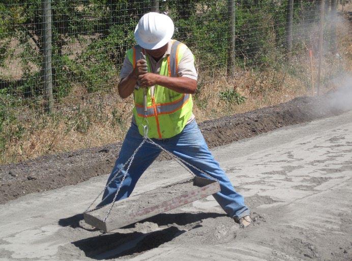
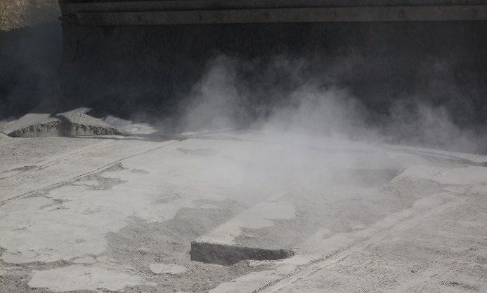

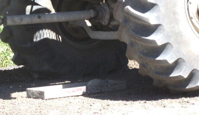
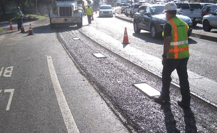
UCPRC-GL-2020-01 119
Figure 6.62: Placing active filler calibration pans on a premilled PDR project.
Figure 6.63: Spreader passing over pan on a prepulverized FDR-C project.
Figure 6.64: Pan after spreader has passed on a PDR-FA project (1% active filler).
Figure 6.65: Pan after spreader has passed on an FDR-C project (4% stabilizer).
Figure 6.66: Weighing a calibration pan on an FDR-C project.
+ Concentrations and overlaps of active filler/stabilizer during spreading can lead to localized excesses, which in turn can lead to localized shrinkage cracking in the recycled base. These cracks can reflect through the asphalt concrete quickly (Figure 6.69 through Figure 6.72). Overlaps of stabilizer and active filler are therefore not permitted.
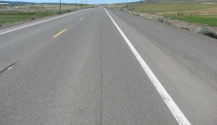


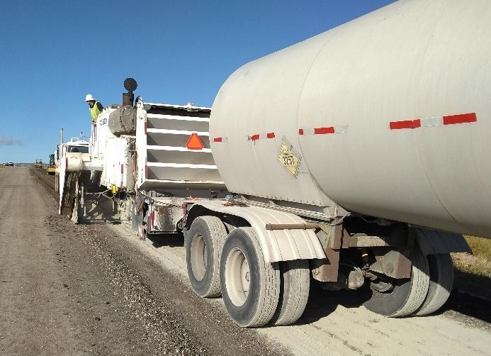
120 UCPRC-GL-2020-01
Figure 6.67: Spreading active filler in a strip that is narrower than the recycler (FDR).
Figure 6.68: Differential stiffness across recycled lane (FDR).
Figure 6.69: Stabilizer accumulation at end of spread on an FDR-C project.
Figure 6.70: Reflected shrinkage crack in area of cement accumulation on an FDR-C project.
Figure 6.71: Overlap of cement spread on an FDRC project (double application).
Recycling widthwiderthan active filler spread 0 10 20 30 40 50 60 0 10 20 30 40 50 60 02468 10121416 SSG Stiffness (klbf/in) LWD Stiffness (klbf/in) Transverse Distance (feet) LWD Stiffness (klbf/in) SSG Stiffness (klbf/in) Milling Machine Width Cement Spreader Width Accumulation Cement overlap
Figure 6.72: Reflected longitudinal crack in area of cement spread overlap (FDR-C).
• Some wheel-driven full-depth recyclers have a tendency to form a wave ahead of the drum housing and/or a windrow on the sides of the mixing chamber that can lead to excesses with similar consequences to those described above (Figure 6.73). Spillage of fine aggregates from the side of the mixing chamber of the recycler may lead to these windrows being covered, making them difficult to detect. These windrows of active filler/stabilizer need to be raked level before the next pass of the recycler.
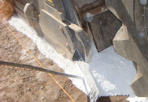
• Spread distances must be reduced in windy conditions (Figure 6.74) or if there is a possibility that the recycling train will need to stop for an extended period (e.g., waiting for asphalt binder delivery).
• Any water sprayed for dust control, compaction, curing, etc., in adjacent lanes must not contact the spread stabilizer or active filler under any circumstances.
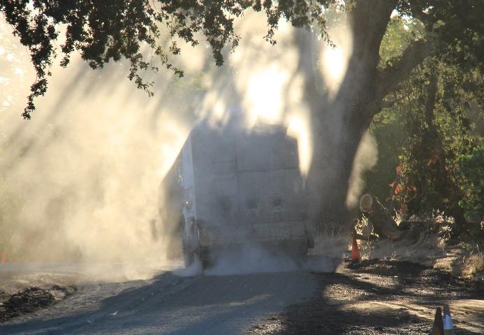
6.3.13 Lateral Joints
Lateral joints are discontinuities across the width of cut that are formed each time the recycling operation stops and starts (e.g., tanker changes, breakdowns, compaction problems, and/or end of daily production). Most problems encountered result from over- or under-application of asphalt recycling agent and/or water at the joint when using single-unit or wheel-driven recyclers, and/or material segregation when the recycler is idling with the drum rotating in the milled material (see Figure 6.24). These problems can be minimized by taking the following steps:
• Limiting the number of production stoppages (e.g., filling the water tanker from another tanker while the train is moving, instead of stopping to switch tankers)
• Lifting the drum completely off the road while the recycler is idling.
• On single-unit and wheel driven recycling trains:
UCPRC-GL-2020-01 121
Figure 6.73: Windrow and wave of active filler on an FDR-FA project.
Figure 6.74: Loss of active filler/stabilizer during windy conditions.
Active filler windrowand wave
Windrow covered byfinematerial
+ Following correct start-up procedures. Bleeding of air from the asphalt binder and water supply lines is especially important. Failure to do this can result in short sections of roadway being recycled with incorrect quantities of binder and/or water.
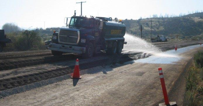
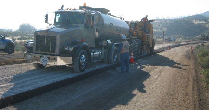
+ Enriching the joint area by reversing the recycling train back into the previously recycled material by the diameter of the milling drum (approximately 5 ft [1.5 m]), thereby ensuring that all material is treated across the effective width of the joint. Before moving forward again, the operator should apply full power and accelerate immediately to the specified operating speed.
6.3.14 Compaction Moisture
Optimal compaction moisture content is critical to ensure that the specified compaction density is achieved. On most FDR projects, and some PDR projects, additional water will be required to supplement the in-situ moisture in the recycled layer to reach the optimal mixing and compaction moisture content. The following considerations are important:
• The compaction water supplied by an attached tanker must be mixed with the material in the mixing chamber of the recycler or central plant. Enough water must be added through the recycler or central plant to meet the design moisture content for completion of primary compaction. No additional water should be added from tankers during primary compaction.
• Under no circumstances should water be sprayed onto the uncompacted material behind the recycler or paver using a separate water tanker (Figure 6.75 through Figure 6.77). Doing this will result in non-uniform distribution of the water throughout the layer, leading to poor mixing and compaction. On FDR-C projects, it can also result in inconsistencies in the hydration of the cement. Poor distribution of compaction water can lead to differential drying and its associated cracking, which can reflect through the asphalt concrete surface (Figure 6.78, photographed approximately five years after completion of the project shown in Figure 6.77).
122 UCPRC-GL-2020-01
Figure 6.75: FDR-FA recycling train with no water tanker.
Figure 6.76: Separate water application behind recycler (FDR).
• On FDR projects, water can be sprayed onto the surface after completion of primary compaction with the padfoot roller to facilitate final shaping and final compaction with the smooth-drum and pneumatic-tired rollers.


6.3.15 Material Placement/Spreading
On PDR projects and FDR projects using track-driven recyclers, the recycled material is either spread behind the recycler using an attached screed, or more commonly, with a paver fed either by a belt or by a pickup machine (Figure 6.79 and Figure 6.80). Any excess material can be removed by shifting the belt feed on the recycler from the paver to a nearby truck (Figure 6.81), or by using a loader and truck if the material is being windrowed.
On CCPR projects, all processed materials are placed with a paver. Material can be dumped directly into the paver, or in a windrow ahead of the paver then transferred to the paver with a pickup machine. Multiple lifts can be placed in this way.

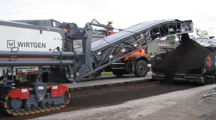
UCPRC-GL-2020-01 123
Figure 6.77: Water application between recycler and primary compaction roller (FDR).
Figure 6.78: Early cracking caused by poor moisture distribution in recycled layer (FDR).
Figure 6.79: PDR project with belt feed into paver.
Figure 6.80: PDR project with pickup machine feeding the paver.
On FDR projects recycled with wheel-driven recyclers, the material is spread by downward pressure of the rear door as it exits the mixing chamber. This material is partially compacted by the rear wheels of the recycler and any attached equipment (Figure 6.82 and Figure 6.83). The extent of this partial compaction (i.e., the height of the uncompacted material) increases with increasing recycle depth. Excess material on FDR projects using wheel-driven recyclers is removed during final shaping and leveling (discussed in Section 6.3.17).
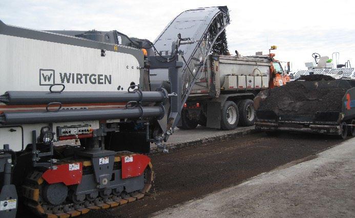
6.3.16 Primary Compaction
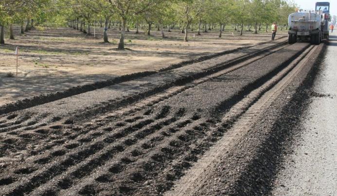
Primary compaction on PDR projects, FDR projects recycled with track-driven recyclers, and CCPR projects, is different than the primary compaction of FDR projects recycled with wheel-driven recyclers. Primary compaction on PDR and FDR projects is discussed separately below. If the material is processed in a central plant, the primary compaction procedures to follow will depend on layer thickness: on thinner layers, PDR compaction procedures will be followed, and on thicker layers, the FDR compaction procedures used behind track-driven recyclers will be followed.
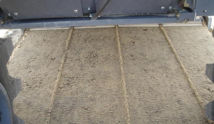
124 UCPRC-GL-2020-01
Figure 6.81: Removing excess material on a PDR project.
Figure 6.82: Material behind mixing chamber on FDR project with wheel-driven recycler.
Figure 6.83: Partial compaction by recycling train wheels on an FDR project.
• On all projects, primary compaction should be based on the test strip and subsequent rolling patterns. New/revised rolling patterns should be established at least once per day and each time there are apparent changes in material properties.
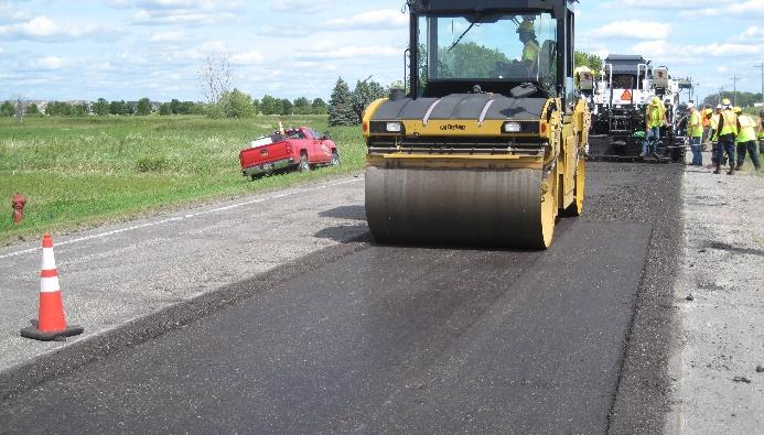
• On PDR projects:
+ During compaction, cold recycled materials look and behave very differently than warm or hot mix asphalt, so care must be taken when trying to compare them. Note that compacted PDR layers typically have higher air-void contents (8 to 16 percent) than asphalt concrete layers (4 to 6 percent).


+ Primary or breakdown compaction on PDR projects is typically carried out with smoothdrum (Figure 6.84) and pneumatic-tired rollers (Figure 6.85) to achieve a breakover (refusal) density (i.e., rolling until density measured with a nuclear gauge does not increase). Rolling typically starts with the smooth-drum roller to provide a smooth starting surface and prevent edge distortion. Starting with the pneumatic-tired roller tends to distort the material, which is difficult to correct with the finishing roller and can lead to smoothness issues. Specifications may require that intelligent compaction procedures are used.
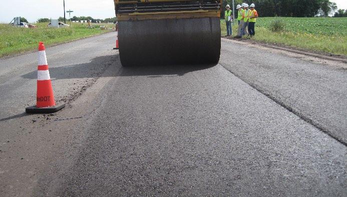
UCPRC-GL-2020-01 125
Figure 6.84: Primary compaction starting with smooth-drum roller on a PDR project.
Figure 6.85: Primary compaction with pneumatic-tired roller on a PDR project.
+ The roller weights on PDR projects are typically heavier than those used on asphalt concrete layers, primarily because of the thicker lifts as well as the nature of the material
(i.e., the higher internal friction between mix particles in PDR projects). Roller weights must be matched to recycled layer thickness.
+ Rollers should be as close as possible to the paver to ensure that the layer is compacted before the moisture starts to evaporate.
+ Longitudinal joints between recycled layers should be compacted first.
+ Initial roller passes should begin on the outside edge and progress inwards, overlapping the passes parallel to the centerline. This helps to prevent lateral shoving of the material.
+ It is critical to ensure that roller drums do not run on the adjacent existing pavement or unrecycled shoulder (Figure 6.86). This leads to bridging, where the weight of the roller is supported by the adjacent pavement and results in a wedge of poorly compacted material in the affected area. Early failure in this area can result (Figure 6.87). The paving crew must clear material on both cut edges so that the roller operator can see where to position the drum to avoid bridging (Figure 6.88).


+ Rolling patterns and procedures, vibration settings, number of roller passes, and moisture control all need to be strictly monitored to ensure that optimal compaction is achieved. No evidence of material shearing should be visible on the surface after completion of primary and subsequent compaction (Figure 6.89).
126 UCPRC-GL-2020-01
Figure 6.86: Roller bridging during primary compaction.
Figure 6.87: Fatigue cracking in asphalt concrete in the bridged area.
Figure 6.88: Raking to clear material and provide a sight line for the roller operator.
Existing shoulder supporting edge of roller
Bridged area with poor compaction
+ On PDR projects with emulsified asphalt:
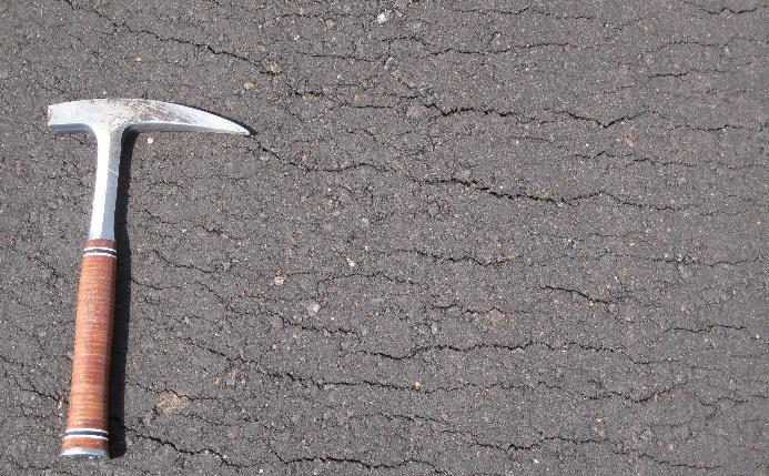
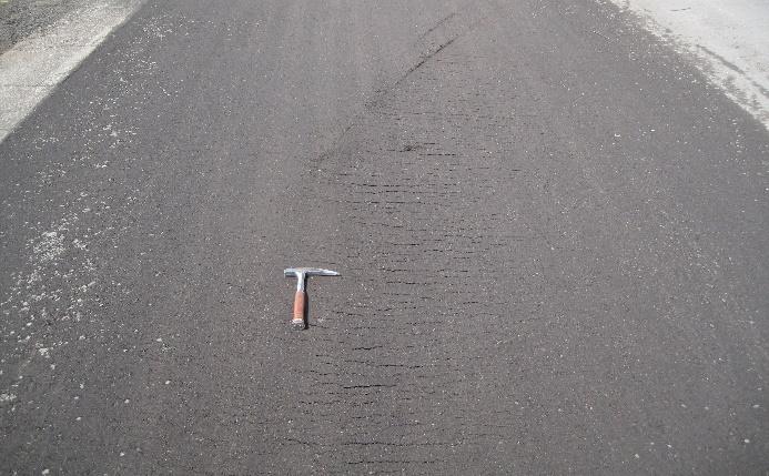
On PDR projects with emulsified asphalt, primary compaction should start as soon as the emulsion starts to break (i.e., when the surface color starts changing from brown to black). This can take anywhere between a few minutes and an hour, depending on the emulsion formulation and weather conditions. Delaying the start of compaction too long after the emulsion starts to break can cause a crust to form on the top of the layer, making compaction more difficult and increasing the likelihood of checking and cracking as shown in Figure 6.89.
• On FDR projects:
+ FDR layers are typically much thicker than PDR layers and therefore usually require heavier rollers. Rollers must be correctly selected and shown to be effective during test strip construction, where density testing must be rigorously carried out to ensure that the specified density is obtained throughout the recycled layer. The use of a roller with insufficient static mass, using low amplitude vibration, compacting very thick layers (i.e., thicker than 1 ft [300 mm]), and/or compacting thick layers on weak or wet supporting layers can result in densification of the material in the upper horizon of the layer only, forming a bridge of compacted material over layers of increasingly lower density. This can lead to differential compaction through the depth of the layer, which in turn can lead to further densification/settlement under traffic, resulting in early rutting and/or cracking.
+ Vibrating or segmented-wheel padfoot rollers are commonly used for the primary compaction of recycled layers thicker than 0.65 ft (200 mm).
+ On tandem recycling trains, one padfoot roller must be used per recycling train and each must be the same make and model, with the same amplitude and vibration settings.
+ High amplitude vibration must be used to achieve maximum penetration of the compactive effort.
+ Roller speed should not exceed 2.0 mph (3.0 km/h) or 165 ft/min (50 m/min).
UCPRC-GL-2020-01 127
Figure 6.89: Shearing after completion of primary compaction on a PDR project.
+ To prevent bridging (described earlier), roller passes must not run onto the adjacent pavement.
+ Primary compaction on roads recycled with wheel-driven recyclers must follow a specific process. Although the material exiting the recycler is in a loose state, the rear wheels of the recycler and the wheels of any towed tankers will run on this material and result in compaction of the loose material in the equipment wheelpaths (Figure 6.83). The inplace density of this compacted material in the wheelpaths is at least 10 percent higher than that of the adjacent uncompacted material. Therefore, it is imperative that before initiating any additional processing, the material between the wheel impressions must first be compacted to at least the same density as that in the wheel impressions. Grading and/or shaping before primary compaction, or failure to compact this material in an appropriate sequence will result in a permanent density differential across the width of the layer, which could lead to premature rutting or longitudinal cracks. An example of the different densities recorded on an FDR project where blading preceded primary compaction is shown in Figure 6.90. On completion of compaction, the density in the recycler wheelpath was 135.1 lb/ft3 (2,164 kg/m3) and the density between the recycler wheelpaths was 125.7 lb/ft3 (2,013 kg/m3). This equates to 99 and 92 percent of relative density, respectively (a difference of 7 percent).
+ Primary compaction on roads recycled with wheel-driven recyclers should be done in the following sequence:

1. The first pass of the padfoot roller should proceed down the center of the recycling train wheelpaths, ensuring that the drum of the roller bridges the impressions (Figure 6.91).


2. At the end of the run (i.e., when the roller catches up with the recycling train), the roller should be reversed back down the same path. If the roller has a blade, it should be lowered on the reverse pass to lightly drag (never push) material into the padfoot impressions and recycler wheelpath impressions (Figure 6.92) If a tandem recycling
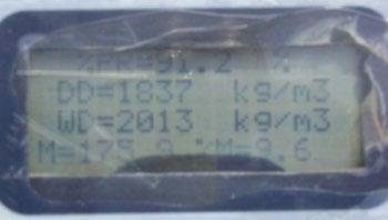
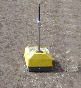
128 UCPRC-GL-2020-01
Figure 6.90: Density measurements in and between recycler wheelpaths (FDR).
Between recycler wheelpaths
In recycler wheelpath
train is used, the padfoot roller behind the second train must follow the same procedure.
3. The material between the recycler wheelpaths should now be level with and of a similar density to that in the impressions. A conventional rolling pattern can then be followed to obtain uniform compaction of the recycled material.


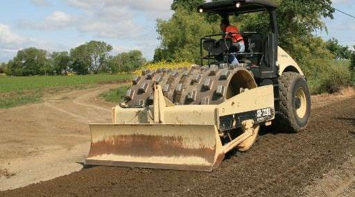
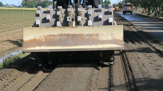
+ As more roller passes are applied, the increasing compactive effort results in increased density in the lower regions of the recycled layer, which increases the resistance to penetration of the individual pads on the roller and allows the roller to “walk out” of the material (i.e., when no impressions are left by subsequent passes of the padfoot roller). Only minor indentations, which must be removed by the grader during leveling, should be left on the surface after completion of primary compaction with the padfoot roller (Figure 6.93 and Figure 6.94).
+ If the recycler maintains a forward speed of about 24 ft/min (8 m/min), the padfoot roller, which typically operates at 165 ft/min (50 m/min) can make five unidirectional passes while keeping pace with the recycling train. If more than five passes are required to achieve the specified density, the speed of the recycling train will need to be reduced, or an additional roller used. If a second roller is used (i.e., two rollers if one recycling train is used and three rollers if two recycling trains are used), it should be the same
UCPRC-GL-2020-01 129
Figure 6.91: First padfoot roller pass on an FDR project.
Figure 6.92: Using the blade to drag material into padfoot impressions (FDR).
Figure 6.93: Padfoot impressions after first roller passes (FDR).
Figure 6.94: Padfoot impressions after multiple roller passes (FDR).
make and model as the other(s), with the same vibration settings. If the roller falls too far behind the recycling train (i.e., typically more than 300 ft [100 m], or when the material dries out and the specified density cannot be achieved throughout the layer [Figure 6.95 through Figure 6.97]), the train must be stopped until the roller catches up. + The cutting of final levels and final compaction should not interfere with primary compaction (Figure 6.98), which should be completed before the grader begins cutting final levels.
6.3.17 Final Grades and Intermediate and Final Compaction
Final grading and compaction should follow immediately after completion of primary compaction, and must be completed within two hours of the mixing water contacting the cementitious active filler or stabilizer. The following considerations are important:

• The final compacted surface should be free of ruts, bumps, indentations, cracks (other than thin drying cracks), segregation of fine and coarse aggregate, and delamination. The completed layer must conform with the planned profile and cross-slope.
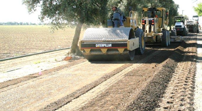
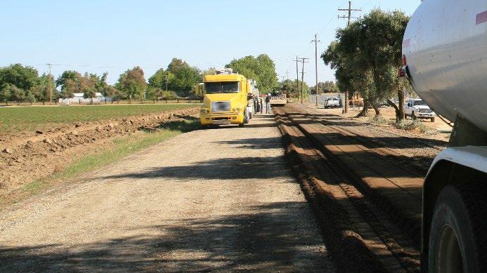
• Water systems should be used on roller drums and tires to prevent material pickup. Release agents should not be used as these may affect asphalt recycling agents.
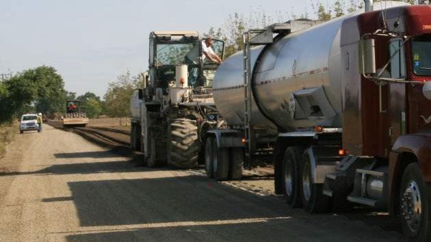
130 UCPRC-GL-2020-01
Figure 6.95: Primary compactor working in close proximity to recycling train (FDR).
Figure 6.96: Primary compactor too far behind recycling train (FDR).
Figure 6.97: Typical maximum distance of padfoot roller behind recycling train (FDR).
Figure 6.98: Final leveling and compaction interfering with primary compaction (FDR).
± 300 ft/100 m
Padfoot roller >300 ft (100 m) behind recycling train.
• On PDR projects:
+ Final grades should be achieved with the paver screed, with no grader work required.
+ Intermediate compaction is typically achieved using a pneumatic-tired roller with its weight selected according to layer thickness.
+ Final compaction, or finish rolling, mostly to smooth out any impressions from the primary and intermediate rolling, is typically achieved with a lighter, smooth-drum roller with no vibration.
+ In most instances, all compaction should be completed without the need for any additional water spraying. Additional water sprays are, however, permitted prior to and/or during final compaction if needed (e.g., hot, dry weather conditions)
+ All compaction must be completed within two hours of the mixing moisture contacting the cementitious active filler
+ Care must be taken to ensure that bridging of the rollers on adjacent pavement sections does not occur (discussed previously in Section 6.3.16).
+ Intelligent compaction may be required on Caltrans PDR projects.


• On FDR projects:
+ The processes followed for final grading and compaction are similar to those for standard aggregate base, but all final grading and compaction must be completed within two hours of the mixing moisture contacting the cementitious active filler (FDR projects with asphalt recycling agents) or stabilizer (FDR-C projects).
+ Some drying out of the material can be expected between the completion of primary compaction and the start of final compaction. Therefore, sufficient water should be sprayed onto the surface prior to grading and during intermediate and final rolling to prevent segregation and/or the formation of laminations, and to ensure that optimum density is achieved in the upper horizon of the layer.
+ Final grades should be cut with the grader after primary compaction is completed, ensuring that all padfoot impressions are removed (Figure 6.99). Failure to remove padfoot impressions can lead to smoothness problems after paving (Figure 6.100).
UCPRC-GL-2020-01 131
Figure 6.99: Shaping and final leveling with a grader on FDR projects.
Figure 6.100: Effect of padfoot impressions on overlay smoothness (FDR).
+ Movement of material with the grader, especially in thin lifts, should be minimized to prevent segregation (Figure 6.101).
+ Material should only be cut, not added, to address problems with low spots. Added material will delaminate and disintegrate (Figure 6.102).

+ Levels, widths, and crossfall should be checked using standard procedures.
+ Excess material is usually bladed to the side of the road and used for shoulder backfill, or collected with a scraper or loader and trucked away for planned minor corrections along the project. A windrow of material must not be left on the side of the road as this will impede drainage and be a safety hazard.

+ Intermediate compaction is typically achieved using a single or double drum steel roller and/or a pneumatic-tired roller with roller weights selected based on layer thickness (Figure 6.103 through Figure 6.105). A rolling pattern should be established and followed.
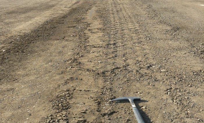
+ Final compaction is undertaken with a smooth-drum vibrating roller, followed by a pneumatic-tired roller. A rolling pattern should be established and followed. No vibration, or a low-amplitude vibration, should be used with the smooth-drum roller and care should be taken not to “overcompact” the material, which will result in aggregate breakdown and/or instability and loss of density. The pneumatic-tired roller is used to
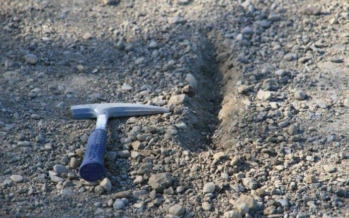
132 UCPRC-GL-2020-01
Figure 6.101: Segregation after excessive movement of material with a grader (FDR).
Figure 6.102: Delamination after blading thin lifts of material during grading (FDR).
obtain a tightly-knit surface finish, which is achieved by spraying water onto the surface followed by rolling (Figure 6.106). Sufficient passes should be applied with the pneumatic-tired roller to achieve the required surface finish. The surface should not be overwatered, as this can lead to segregation of the surface material, laminations, and/or weak spots.
• On PDR projects with emulsified asphalt + PDR projects recycled with emulsified asphalt may need secondary compaction to remove minor consolidation in the wheelpaths caused by traffic while the recycled material is still curing (discussed in Section 6.3.19). For this compaction, a rubber-tired
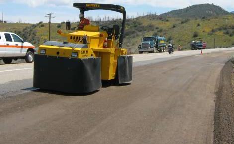
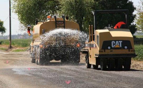
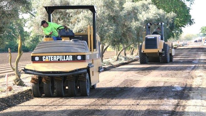
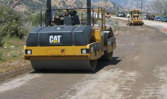

UCPRC-GL-2020-01 133
Figure 6.103: Intermediate rolling on FDR layer with single drum steel roller.
Figure 6.104: Intermediate rolling on FDR layer with double drum steel roller.
Figure 6.105: Intermediate rolling on FDR layer with steel-drum and pneumatic-tired rollers.
Figure 6.106: Final rolling on FDR projects with pneumatic-tired rollers.
roller should be used first, followed by a smooth-drum roller with no vibration. These are typically the same rollers used for intermediate and final rolling during the first round of compaction. A rolling pattern and break-over curve must be established in the same manner as during initial compaction Where feasible, secondary compaction should be done during the warmer part of the day.
6.3.18 Quality Control and Quality Assurance
Key quality control considerations on in-place recycling projects include compaction, thickness, grade, and visual condition Smoothness of the recycled layer is an acceptance criterion for PDR layers.
Strength tests are currently specified for PDR-FA, FDR-FA, and FDR-C projects. Although useful for checking that layer strengths match those determined in the mix design, they are impractical given the time they take to obtain a result (minimum four days for asphalt-treated materials and minimum eight days for cement stabilized materials). As of this writing, a National Cooperative Highway Research Program (NCHRP) project is investigating rapid quality control/quality assurance tests that can determine when a recycled layer can be opened to traffic and/or paved based on shear (rutting) and raveling resistance. These tests should be considered for Caltrans projects and in Caltrans specifications if they prove to be effective and are adopted by AASHTO.
Consider the following for quality control/quality assurance:
• Compaction must meet the specification and/or special project provision requirements.
+ On PDR projects, this typically requires a nuclear density gauge measurement following CT-375 on layers less than 0.35 ft. thick, and CT-231 on layers thicker than 0.35 ft., checked against a breakover curve. Each measurement must meet or exceed the specified density.
+ On FDR projects, this typically requires a nuclear density gauge measurement (CT-231) checked against a site laboratory-determined wet density (CT-216) for every lot. Each measurement must meet or exceed the specified density.
+ On FDR projects, measurements must be taken at two or three heights depending on the recycled layer thickness (e.g., two on layers 0.8 ft [250 mm] thick or less and three on layers thicker than 0.8 ft) to ensure that density requirements have been met over the full depth of the layer.
• Thickness control immediately after final compaction is difficult on in-place recycled materials because the layer cannot be cored until it has cured, which can take a number of days. By this time, it is difficult to take corrective action. Recycle depth can be monitored
134 UCPRC-GL-2020-01
during recycling to get an indication of thickness. A dynamic cone penetrometer (DCP) or ground-penetrating radar (GPR) can also give a reasonable initial indication of layer thickness immediately after compaction In most instances, acceptance is still based on cores when they can be taken (usually the same core taken to check asphalt concrete thickness). If the recycled layer thickness is less than the design thickness, the difference needs to be made up with asphalt concrete.
• Grade requirements (primarily lane width and crossfall) must meet design requirements and are measured using standard surveying techniques.
• Visual condition entails checking for problems including, but not limited to, debonding, delamination, segregation, cracks, deformation, soft areas, and/or raveling caused by construction traffic. The contractor will be required to take corrective actions to remedy any problems.
6.3.19 Curing
Recycled layers must dry back before they are surfaced. On two-lane roads, the recycled layers can usually be opened to traffic within a few hours after final compaction, provided that appropriate measures are taken to seal the surface and reduce traffic speeds. Considerations for curing include the following:
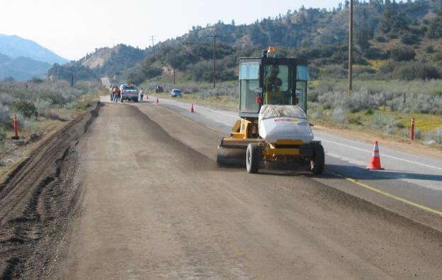
• Brooming, if required, must be done with care and only light pressure to prevent damage to and raveling of the uncured recycled layer surface (Figure 6.107).
• A curing seal that meets specification requirements (e.g., the emulsified asphalt used in tack coats diluted to 50 percent and applied at a rate typically between 0.1 and 0.2 gal/yd2 [≈ 0.5 and 0.9 L/m2]) should be applied on all recycled layers followed by an application of sand (1 to 2 lb/yd2 [≈ 0.5 to 1 kg/m2]), prior to opening to traffic (Figure 6.108 and Figure 6.109).
UCPRC-GL-2020-01 135
Figure 6.107: Light brooming prior to curing seal application on an FDR project.
• Temporary striping can be painted as soon as the curing seal emulsion has broken and the sand has bonded to it. Pop-up lane markers must not be used because they do not adhere to the recycled layer surface.
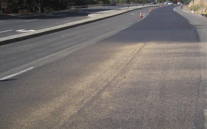
• On FDR-C projects:
+ Water-spraying for curing purposes is generally not appropriate on FDR-C projects because it is very difficult to ensure that the recycled layer will be kept at a constant moisture content throughout the curing period. Allowing the recycled layer to go through multiple wetting and drying cycles can lead to carbonation on top of the layer (Figure 6.110), and cause weakening, break-up, and raveling of the surface (Figure 6.111) (an introduction to carbonation of cement-treated layers is provided in Appendix A). The extent and depth of carbonation can be determined by spraying phenolphthalein on potentially affected areas. Intact areas will turn crimson, while carbonated areas will not change color, and just appear as a clear “wet” spot.
+ Carbonated, raveled, and/or debonded material must be removed (broom or grader) and the thickness made up with asphalt concrete.


136 UCPRC-GL-2020-01
Figure 6.108: Curing seal application on a PDR project.
Figure 6.109: Curing seal after application of sand on a PDR project.
Figure 6.110: Carbonation on an FDR-C layer caused by repeated wetting and drying cycles.
Figure 6.111: Breakup of surface of an FDR-C layer caused by carbonation.
Uncarbonatedmaterial below surface Carbonation of surface material
6.3.20 Opening to Traffic
In-place recycled layers typically have sufficient strength to open to traffic within one to four hours after final compaction In this period, the emulsified asphalt curing spray and sand application will have set up and temporary paint markings will have dried. The following considerations regarding opening to traffic are important:
• Appropriate traffic control, speed control, and signage requirements must be adhered to at all times.
• During the curing period and prior to the placement of the asphalt concrete surfacing, the recycled layers remain susceptible to damage by traffic, specifically to permanent deformation and raveling. If possible, the use of the road by heavy truck traffic should be limited until the wearing course has been placed.

• Traffic controls for the remaining days of recycling must also be carefully planned to ensure that traffic waiting at the Stop/Go control points does not stand on a section of recycled pavement that is less than 24 hours (and preferably 48 hours) old. Vehicles waiting on the recycled pavement before that period may leave permanent wheel impressions on the surface (Figure 6.112).
• In the period of trafficking prior to placement of the surfacing, the road should be monitored carefully each day to identify problem areas that need repair. The cause of any problems should be identified together with appropriate corrective actions. Potential problems could include, but are not limited to, the following:
+ Raveling, which is usually caused by low asphalt recycling agent contents, carbonation on cement-stabilized layers, inappropriate curing procedures or curing seal application rates, or excessive blading and/or brooming of the surface after compaction.
+ Cracking, which is usually caused by rapid drying of the layer, contamination of the recycled layer with plastic fines, higher-than-design contents of cement active filler/stabilizer, incorrect compaction procedures, and/or inappropriate curing procedures.
UCPRC-GL-2020-01 137
Figure 6.112: Permanent truck tire impressions on a PDR layer.
+ Rutting, which is usually caused by inadequate compaction, too-low asphalt recycling agent contents, overwetting of the surface, and/or opening to traffic too soon.
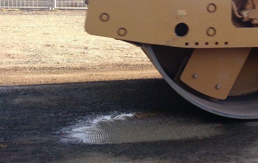

6.3.21 Shrinkage Crack Mitigation (Microcracking) on FDR-C Layers
Shrinkage crack mitigation, or microcracking, is required on all FDR-C layers between 48 and 56 hours after final compaction of the layer. The Caltrans method specification that must be followed states: “During the period from 48 to 56 hours after compaction, microcrack the surface by applying 2 to 3 single passes using a 12-ton vibratory steel-drum roller at maximum amplitude travelling from 2 to 3 mph” (Figure 6.113 and Figure 6.114). The road should be lightly sprayed with water prior to starting microcracking.
Although not required in the specifications, the contractor may check the effectiveness of the shrinkage crack mitigation by measuring the stiffness with a soil stiffness gauge or light weight deflectometer after each roller pass (Figure 6.115 and Figure 6.116). The target stiffness reduction is typically 40 percent. Stiffness reduction below the target level implies that shrinkage crack mitigation has not been achieved and that shrinkage cracks in the recycled layer will likely reflect through the asphalt surfacing. Stiffness reduction above the target level implies that permanent damage may have been caused to the layer and that no stiffness recovery/increase, or only a limited amount, will occur.
Areas with inappropriate curing seal applications (Figure 6.117) and/or carbonation, delamination, or debonding will usually be exposed after microcracking (Figure 6.118).
138 UCPRC-GL-2020-01
Figure 6.113: Shrinkage crack mitigation (microcracking) on an FDR-C layer.
Figure 6.114: Close-up view of microcracking showing vibrations applied to road surface.
6.3.22 Surfacing

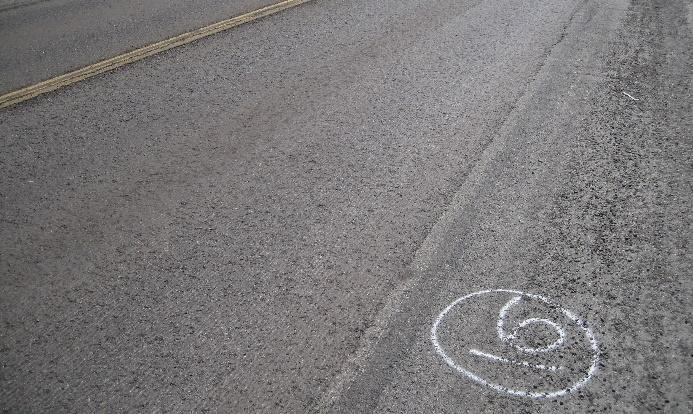

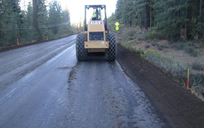
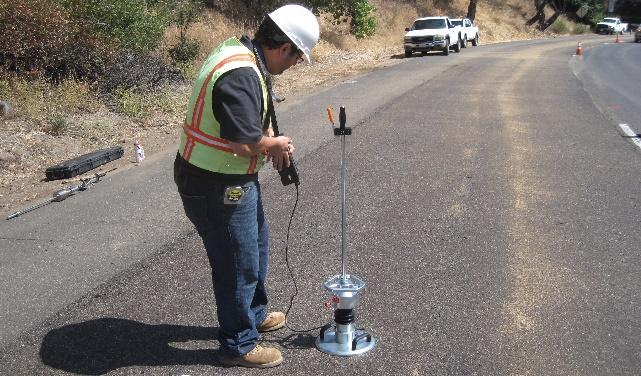
Surfacings should not be placed on the recycled layer until the material has dried back to between 30 and 50 percent of the optimum moisture content. Micromilling of the cured recycled layer surface to improve smoothness and remove minor irregularities is permitted, provided that the design layer thickness is maintained (Figure 6.119). A fog seal should be applied after micromilling to seal the surface and reduce any potential for raveling.
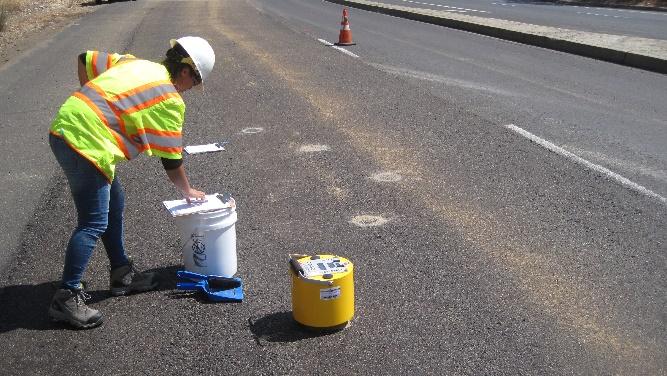
UCPRC-GL-2020-01 139
Figure 6.115: Checking stiffness reduction with a soil stiffness gauge.
Figure 6.116: Checking stiffness reduction with a light weight deflectometer.
Figure 6.117: Damage to emulsion curing seal during shrinkage crack mitigation (FDR-C).
Figure 6.118: Delaminated area exposed during shrinkage crack mitigation (FDR-C).
Figure 6.119: PDR layer milled for smoothness prior to placing asphalt concrete surface.
The project should be inspected before approval to place the surfacing is given. All problem areas must be repaired (usually by removal and replacement with asphalt concrete [Figure 6.120]), and all loose material broomed from the surface (the broom should not cause the surface to ravel).

Surfacings must not be placed onto a raveled surface (Figure 6.121 and Figure 6.122).

Tack coats must be applied prior to placing the asphalt concrete to ensure a good bond between the recycled layer and the asphalt concrete. The emulsified asphalt seal applied for curing purposes (Section 6.3.19) is not considered as a tack coat for the asphalt concrete surfacing.
Surfacings, typically asphalt concrete, must be placed according to the relevant standard specifications.
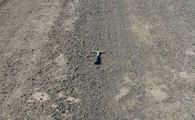
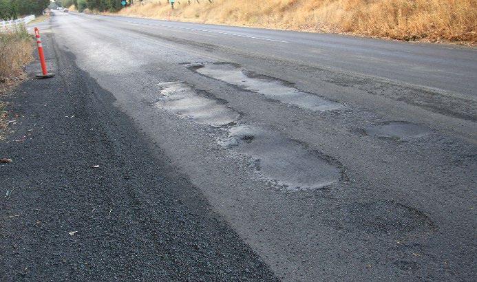
6.3.23 Drainage
Recycled pavement performance, like that of all other pavements, is sensitive to moisture, so adequate, functioning drainage is imperative to ensure good performance throughout the design
140 UCPRC-GL-2020-01
Figure 6.120: Patched distressed areas prior to surfacing.
Figure 6.121: Acceptable surface prior to tack coat application.
Figure 6.122: Unacceptable surface prior to tack coat application.
life of the rehabilitated road. The following need to be checked during construction and before the project is closed:
• That adequate crossfall has been provided along the length of the project to ensure that water can drain off the road and that no localized ponding will occur in low spots.
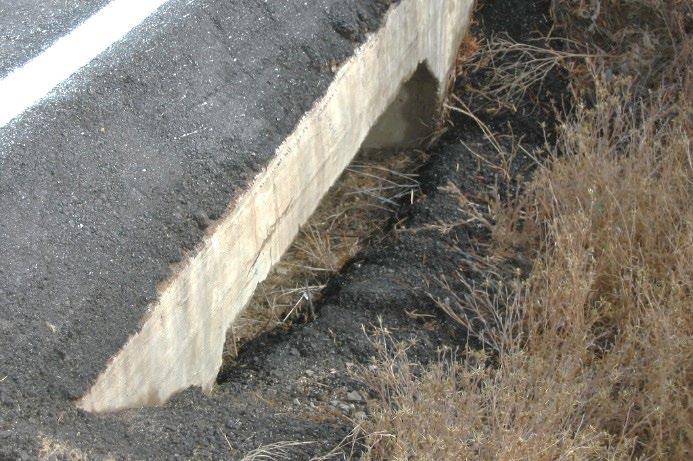
• That side drains and drain turnouts have been cleared to ensure that water can drain away from the road and will not pond near the structure. This is particularly important on roads that do not have wide shoulders.
• That culverts have been checked for blockages, and that all excess construction material has been cleared from inlets and outlets (Figure 6.123 and Figure 6.124) so water will not pond near them.
• That irrigation channels and ditches have been checked to ensure that they do not interfere with road drainage.
UCPRC-GL-2020-01 141
Figure 6.123: Excess asphalt concrete blocking a culvert after placement.
Figure 6.124: Soil blocking a culvert after completing an FDR project.
Excess asphalt
142 UCPRC-GL-2020-01 Blank page
REFERENCES
1. Highway Design Manual. 2020. Sacramento, CA: California Department of Transportation (dot.ca.gov/-/media/dot-media/programs/design/documents/hdm-complete032020.pdf).
2. Jones, D., Fu, P. and Harvey, J.T. 2009. Full-Depth Reclamation with Foamed Asphalt in California: Guidelines for Project Selection, Design, and Construction. Davis and Berkeley, CA: University of California Pavement Research Center. (UCPRC-GL-2008-01).
3. Maintenance Technical Advisory Guide: Volume I – Flexible Pavement Preservation, Second Edition. Sacramento, CA: California Department of Transportation (dot.ca.gov/programs/ maintenance/pavement/mtag/mtag-flex).
4. Santos, J., Bryce, J., Flintsch, G., Ferreira, A. and Diefenderfer, B. 2015. A Life-Cycle Assessment of In-Place Recycling and Conventional Pavement Construction and Maintenance Practices. Structure and Infrastructure Engineering. Taylor and Francis.
5. Saboori, A., Harvey, J., Lea, J. and Jones, D. 2020. A Framework for Selection Between EndOf-Life Alternatives at the Project-Level Considering Full Life-Cycle Environmental Impacts. Proceedings of the 2020 Conference on Pavement, Roadway, and Bridge Life Cycle Assessment. CRC Press.
6. Al-Qadi, I.L., Ozer, H., Diefenderfer, B. and Zhou, Q. 2020. Pavement Recycling: A Case Study of Life-Cycle Assessment and Life-Cycle Cost Analysis. Proceedings of the 2020 Conference on Pavement, Roadway, and Bridge Life Cycle Assessment. CRC Press.
7. Amarh, E., Oliveira dos Santos, J., Flintsch, G. and Diefenderfer, B. 2020. Development of Pavement Performance Prediction Models for In Situ Recycled Pavements in Virginia. Proceedings of the 2020 Conference on Pavement, Roadway, and Bridge Life Cycle Assessment. CRC Press.
8. Jones, D., Fu, P. and Harvey, J.T. 2008. Full-Depth Reclamation with Foamed Asphalt in California: Final Report. Davis and Berkeley, CA: University of California Pavement Research Center. (Research Report: UCPRC-RR-2008-07).
9. Jones, D., Louw, S. and Wu, R. 2015. Full-Depth Recycling Study: Test Track Construction and First-Level Analysis of Phase 1 and Phase 2 HVS Testing, Forensic Investigation, and Phase 1 Laboratory Testing. Davis and Berkeley, CA: University of California Pavement Research Center. (Research Report: UCPRC-RR-2015-02).
10. Jones, D., Louw, S., Hammack, J., Wu, R., Buch, K. and Harvey, J. 2020. Full-Depth Recycling Study: Phase 2 and Phase 3 Laboratory Testing and Second-Level Data Analysis Davis and Berkeley, CA: University of California Pavement Research Center. (Research Report: UCPRCRR-2020-05).
UCPRC-GL-2020-01 143
11. Louw, S., Jones, D. and Hammack, J. 2016. Pavement Recycling: Shrinkage Crack Mitigation in Cement-Treated Pavement Layers — Phase 1 Laboratory Testing. Davis and Berkeley, CA: University of California Pavement Research Center. (Research Report: UCPRC-RR-2016-07).
12. Louw, S., Jones, D. Hammack, J., and Harvey, J. 2020 Pavement Recycling: Shrinkage Crack Mitigation in Cement-Treated Pavement Layers — Phase 2a Test Road Construction and Monitoring. Davis and Berkeley, CA: University of California Pavement Research Center. (Research Report: UCPRC-RR-2019-05).
13. Louw, S., Jones, D. Hammack, J., and Harvey, J. 2020 Pavement Recycling: Shrinkage Crack Mitigation in Cement-Treated Pavement Layers — Phase 2b Laboratory Testing and Performance Modeling. Davis and Berkeley, CA: University of California Pavement Research Center. (Research Report: UCPRC-RR-2020-04).
14. Basic Asphalt Recycling Manual. 2015. Annapolis, MD: Asphalt Recycling and Reclaiming Association.
15. Reeder, G.D., Harrington, D.S., Ayers, M.E. and Adaska, W. 2019. Guide to Full-Depth Reclamation (FDR) with Cement. Skokie, IL: Portland Cement Association (SR1006P).
16. Wirtgen Cold Recycling Technology. 2012. Windhagen, Germany: Wirtgen GmbH.
17. Bitumen Stabilized Recycling: Laboratory Handbook. 2017. Windhagen, Germany: Wirtgen GmbH.
18. A Guideline for the Design and Construction of Bitumen Emulsion and Foamed Bitumen Stabilised Materials. 2020. Pretoria, South Africa: Asphalt Academy (Technical Guideline TG2, 3rd Edition).
19. Jones, D., Wu, R. and Harvey, J. 2020. Site Investigation Guide for Mechanistic-Empirical Design of California Pavements. Davis and Berkeley, CA.: University of California Pavement Research Center. (Guideline: UCPRC-GL-2020-02). (Under review at the time of writing this guideline).
20. Jones, D. and Harvey, J. 2005. Relationship Between DCP, Stiffness, Shear Strength and R-Value. Davis and Berkeley, CA.: University of California Pavement Research Center. (Technical Memorandum: UCPRC-TM-2005-12).
21. Paige-Green, P. 2015. Cementitious Stabilization of Road Materials. Pretoria, South Africa: Council for Scientific and Industrial Research.
22. Life-Cycle Cost Analysis Procedures Manual. 2013. Sacramento, CA: California Department of Transportation.
23. Jones, D., Louw, S. and Hammack, J. 2020. Full-Depth Recycling Study: Phase 4 Laboratory Testing Davis and Berkeley, CA: University of California Pavement Research Center. (Report in preparation).
144 UCPRC-GL-2020-01

