i.d.e.a. Museum Renovations - 15% Schematic Design Report
project team
Owner
City of Mesa
JENNIFER DONAHUE
Project Manager
JULIE CHRISTOPH
Project Manager
CINDY ORNSTEIN
Director of Arts & Culture
BRIAN SPOON
Engineering / Facilities
i.d.e.a. Museum
JEFFORY MORRIS
Museum Curator
DYAN SEABURG
Interim Director
DENA MILLIRON
Museum Education Curator
ILLYA RISKE
Dep. Director of Arts & Culture
Design
Holly Street Studio Architecture
DIANE JACOBS
Principal In Charge
ANNETTE PARK
Project Designer
Dig Studio Landscape Architecture
CHAD ATTERBURY
Lead Landscape Architect
Museum Planning
Gyroscope, Inc.
Museum Planning Consultants
MAERYTA MEDRANO
Museum Planning Consultant
Engineering
Pangolin Structural
Structural Engineering
CRYSTAL BLANTON
Lead Structural Engineer
Energy Systems Design
MEP Engineering
MONTE STURDEVANT
Lead Mechanical Engineer
NATHAN SHORT
Lead Electrical Engineer
Dibble Engineering Civil Engineering
ADRIAN CARVAJAL
Lead Civil Engineer
of contents
I. Project Summary
II. Project Priorities
III. Proposed Plan + Phasing
IV. Square Footage Summaries & Comparisons
V. Conceptual Views
VI. Schematic Design Documents (15%)
VII. Engineering Narratives
VIII. Appendix
I. PROJECT SUMMARY
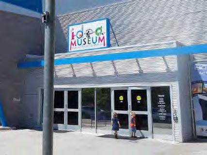
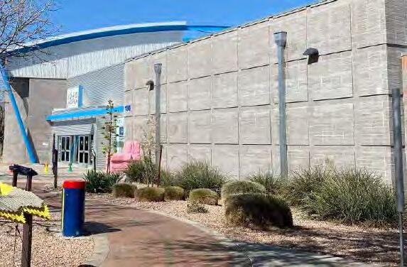
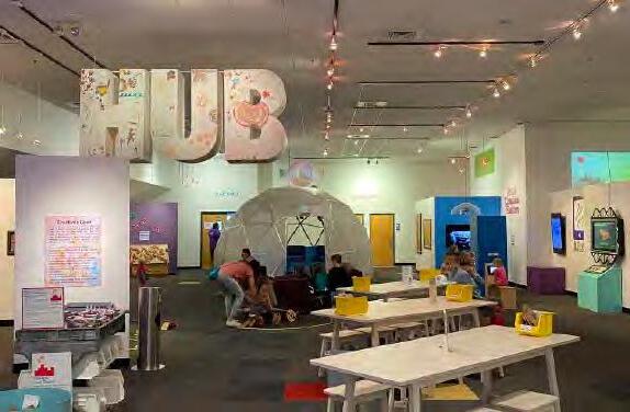
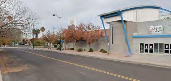
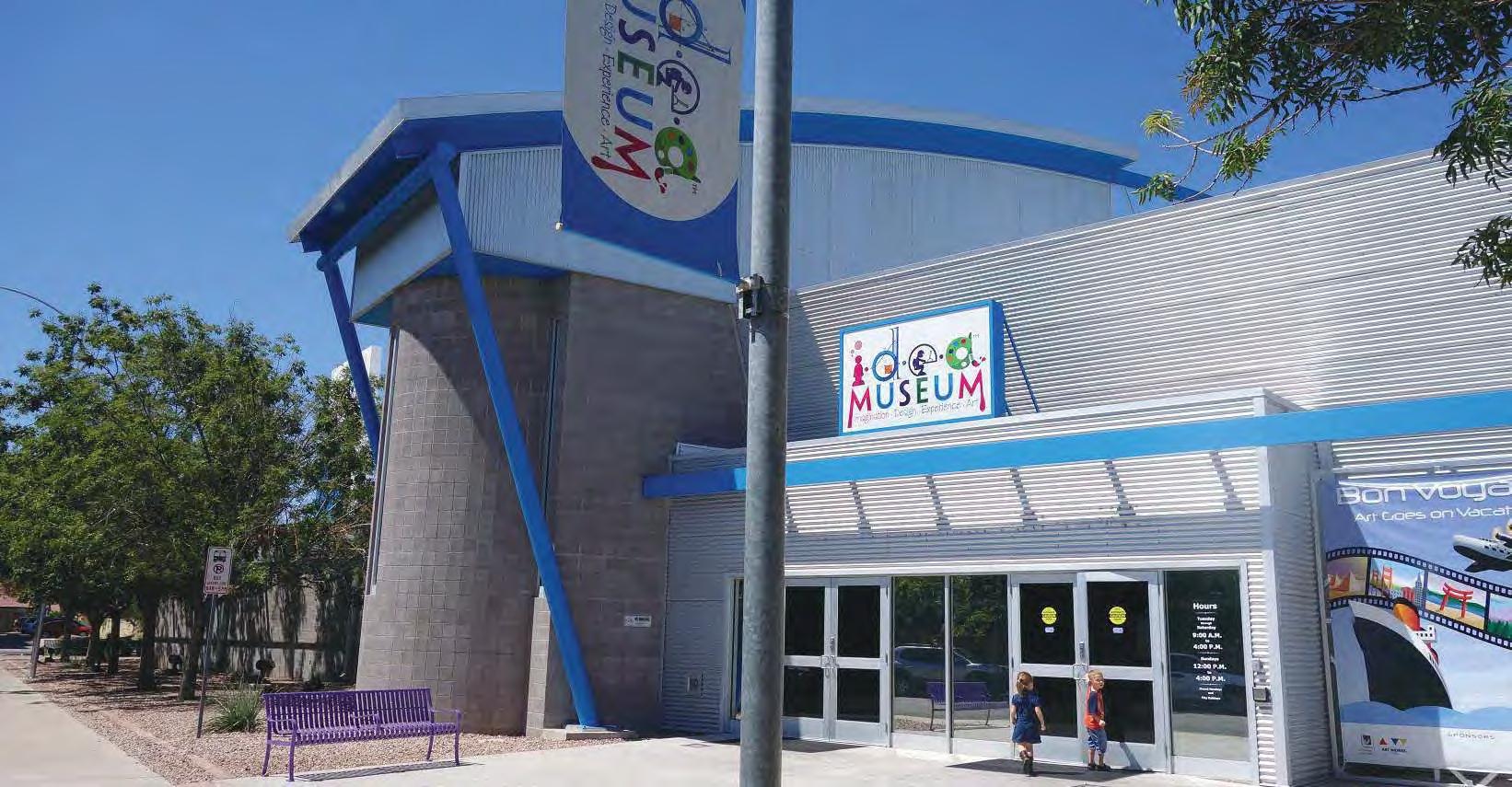
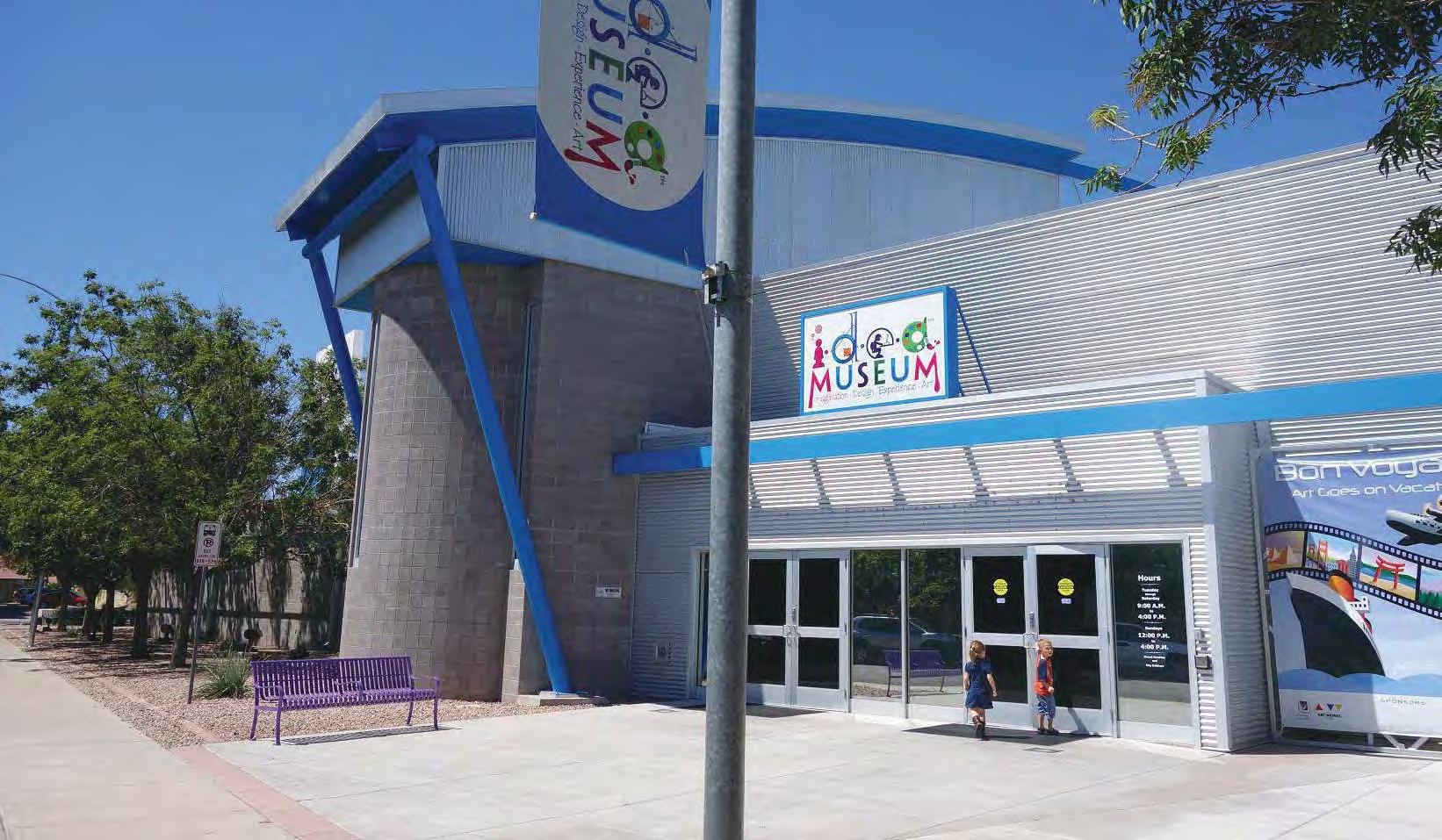
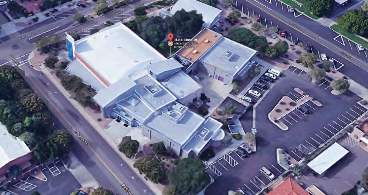
Operated by the City of Mesa, the museum attracts over 90,000 annual visitors, providing art exhibitions and STEAM activities focused on supporting early learning, nurturing creative thinking, and engaging families. The i.d.e.a. Museum Renovation Project re-purposes existing spaces within the current museum building [a former Bashas grocery store] to create new galleries, interactive public spaces, offices, and a new entrance zone in keeping with overall strategies and recommendations from the 2018 . The recommendations for architectural renovations are based 2018 i.d.e.a. Museum Artooze Site Master Plan by Gyroscope Inc. and informed by the 2019 Feasibility Report by EMC2 as well as the City of Mesa’s Scope Diagram and priority spaces - see right.
About the Museum:
“Founded in 1978 by Jack and John Whiteman, the i.d.e.a. Museum was originally known as the Children’s Fine Art Center. It was the only children’s museum in the United States to focus on fine art, providing interactive art exhibitions to introduce children to the world of art and encourage self- expression. The name was changed to the Arizona Museum for Youth (AMY) in 1981 and was rebranded as the i.d.e.a. Museum in 2014. Today the Museum is a 501(c)3 public-private partnership between the City of Mesa and the i.d.e.a. Museum Board of Directors, Inc. The Museum uses art as the inspiration and vehicle to explore concepts in science, engineering, math, history, cultures, and language arts, often using technology as a facilitation tool. Programs and exhibitions are focused on early learning needs and statewide school standards.”
Goals for this Phase:
- Gyroscope Inc Site Masterplan, June 2018
Enclosed within, is a detailed review existing architecture, systems + exterior conditions and recommendations for capturing the programmatic and flow delineated in the Master Plan of 2018. The conceptual design that focuses on exposing the texture and geometry of the building, maximizing existing square footages, opening and connecting indoor and outdoor exhibit spaces, upgrading systems, and providing more places to explore + create inside and out. Plans + Narratives attached represent a 15% Schematic Design level intended for the development of a conceptual cost estimate leading to implementation and construction. Priorities begin and end with exhibit space, focusing on the adaptability, possibility and accessibility for kids of all ages.
project priorities | City of Mesa + i.d.e.a. Museum
PRIORITY
ONE
1. Staff Office Relocation & Renovation
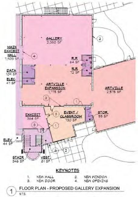
2. Artville Gallery Expansion
3. Daylight at Existing Artville Gallery
4. Texture Trails Early Childhood Garden
PRIORITY TWO
5. Landscape Improvements at Atrium
6. New Main Entry Zone at Pepper
7. Main Exhibit Hall Renovation
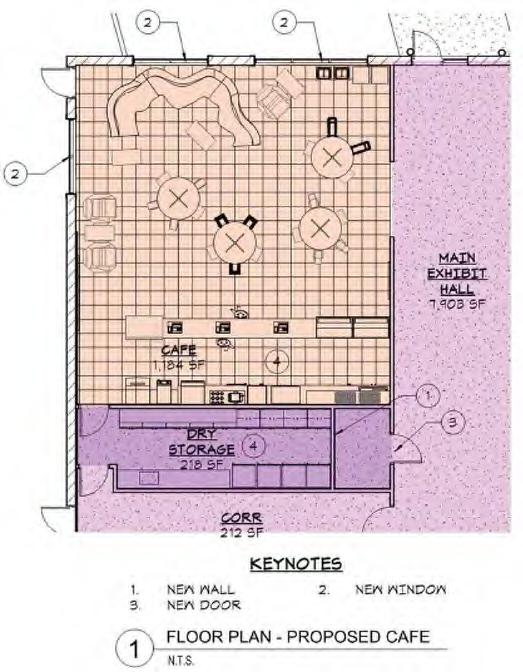
8. New Café
9. New Gift Shop - Now Kiosks
10. Second Level Program + Staff Space
Main Exhibit RR +
Artville 1 RR + Classroom Upgrades
13. Fabrication Lab Upgrades
14. West Entry (site + canopy) Upgrades
15. Cafe (site + canopy) Upgrades
16. Cafe Expansion
17. Admin Courtyard
18. Trash Enclosure Modification
19. East Site Upgrades
20. Pepper Place Expansion
Atrium
Museum Entrance Entrance Lobby
I. PROJECT SUMMARY | Previous Studies
i.d.e.a. MUSEUM Artooze Site Masterplan 2018 | Gyroscope Inc.
“...With increased demand for more programming, new visitor amenities, more exhibits and more dedicated spaces for early childhood families, the Museum has embarked on a visionary Site Master Plan to meet these needs.
Goals of Site Masterplan project:
• Create High Visibility and Leadership in the Arts and Innovation District.
• Increase Attendance, Earned Revenue, And Capacity.
• Activate, Reorganize, and Leverage Underutilized Areas of the Building and Site.
• Improve Quality of Visitor Experience, Adding Amenities and Expanded Program Offerings
• Be Responsible Stewards of the City’s And Museums’ Donor Investments through Strategic Capital Improvements that Impact the Bottom Line.
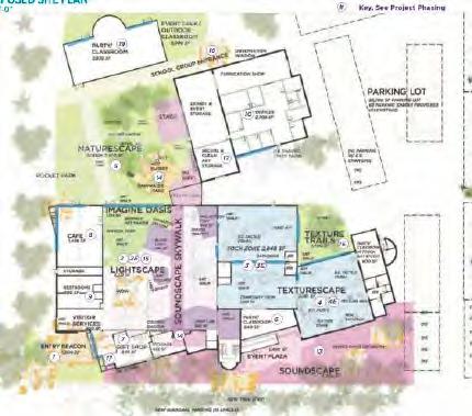
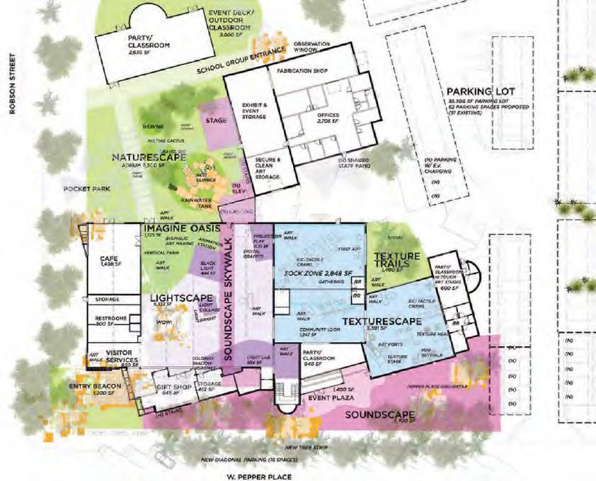
Informed by a conceptual theme of “ARTOOZE”, the Gyroscope Site Masterplan organizes exhibits and public space into four distinct zones (Lightscape, Texturescape, Soundscape, and Naturescape), embodying the i.d.e.a. Museum’s mission of infusing Imagination, Design, Experience, and Arts throughout the site.
Strategies
• Space Re-Organization
• Increased Street Visibility
• Improved Visitor Experience
Feasibility Report 2019 | EMC2
“...The i.d.e.a. Museum, constructed in 1995 by re-purposeing the original 1950’s Basha’s Grocery Store underwent a second major remodel and addition in 2002. The Feasibility Report is to determine the constructability and associated costs for the design recommendations made in the Gyroscope Masterplan to increase and improve capacity, function, branding, and programs.” Tasks within this project included:
Review of Costs & Feasibility of:
• Exposing Bowstring Trusses In Main Exhibit Hall.
• Relocating Electrical Room At North Side Of Main Exhibit Hall.
• Installing Windows In Exterior Walls At 11 Separate Locations.
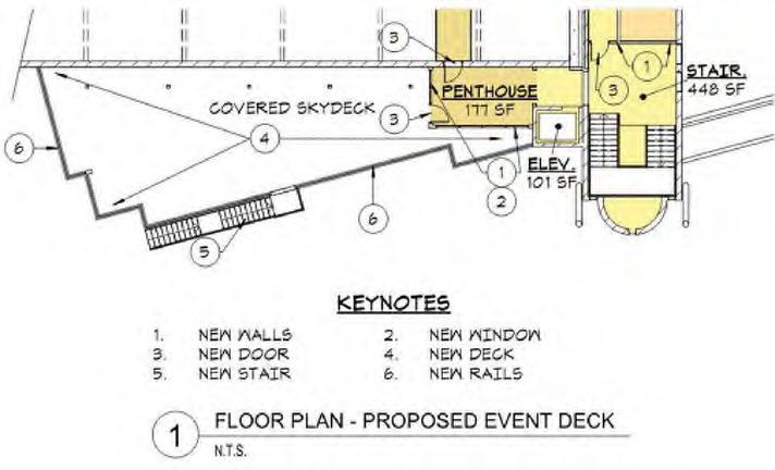
• Converting The Roof Of One-Story Spaces On South Side into an Event Deck.
Additionally, the EMC2 team evaluated the impact of design options in several key areas, including the Fabrication Shop, Artville & Artville Expansion, 2nd Floor Offices, Main Exhibit Hall, Cafe, New Entry, Gift Shop, Atrium Classroom, and an Event Deck. The final report also included preliminary cost summaries for each altered space, detailing new or relocated MEP system requirements, structural implications, and conceptual design layout suggestions.
Gyroscope Masterplan - Main Exhibit Concept
EMC2 - Feasibility Report
II. PROJECT PRIORITIES | One
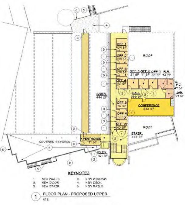
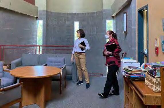
1. Staff Office Relocation
Relocation of administrative offices from the first floor of main building to Building 2 creates 4,000sf + of new gallery space and brings design, development and educational staff under one roof.
• Relocate all museum staff to single location at ground level.
• Create efficient layout and flexible work zones + offices.
• Provide spaces for meetings and break room.
• Harvest daylight, connect to outdoor space.
• Increase proximity to fabrication lab and exhibition operations.
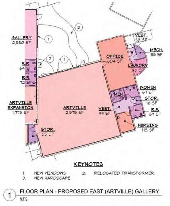
2. Artville Gallery Expansion
With administrative offices relocated from main building first floor space, the Artville Gallery will expand into Artville 2 with new exhibits that grow popular experiences for younger children and older siblings.
• Create direct link and visibility from Artville 1 to Artville 2.
• Expand existing gallery space and exhibit opportunities.
• Improve visibility and connection to entry hall and amenities.
• Increase flexibility and program opportunities for revenue.
• Upgraded MEP system. New drinking fountain.
• Connection to exterior Texture Trails outdoor exhibit.
3. Daylight at Existing Artville Gallery
Existing Artville Gallery - now Artville 1, will open directly into the new Texture Trails outdoor exhibit gallery. This connection brings much needed daylight into the space and direct access to outdoor activities linked to indoor experiences as well as loading zone.
• Grow existing masonry opening to with glazed garage doors.
• Open exhibit space to garden views.
• Increase comfort and energy efficiency with outside air.
4. Create Texture Trails at Early Childhood Garden
Demolition of existing hard, non-porous surfaces to be replaced by natural elements, intermittent paving, power and water for interpretive displays.
• New outdoor exhibit area with revised hardscape and landscape.
• Create zone for interactive biophillia installations.
• Connect to larger courtyard adjacent to staff space, with low gate structure to divide and or connect as needed.
• New trees, planting and water sources for play and discovery.
• Expansion of area with demolition of patio space along east wall.
II. PROJECT PRIORITIES |
5. Atrium Landscape Improvements
Work with existing grades and hardscape to open atrium zone for larger spectator crowds and lunch zone
• Align existing hardscape geometry to create more efficient, open green space at exterior courtyard and new gathering zone for picnics at cafe.
• Create performance stage at east side of Atrium space
• Provide space to add new sculptures, play components post construction.
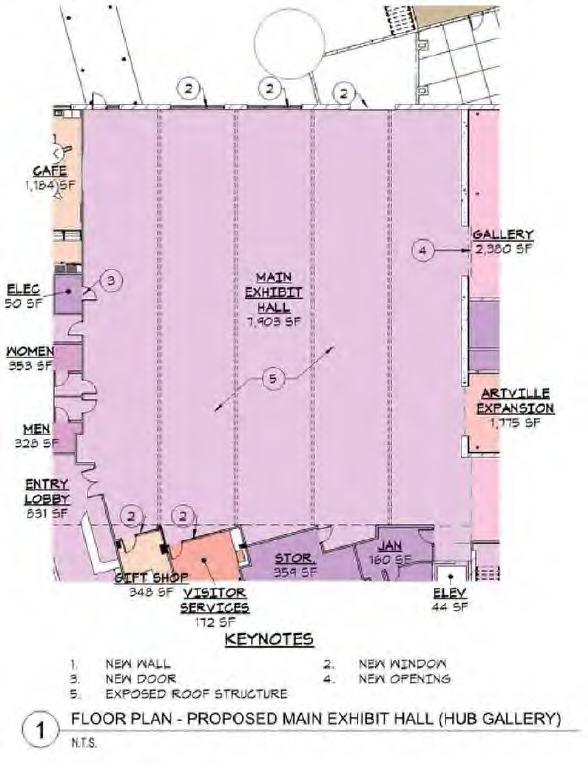
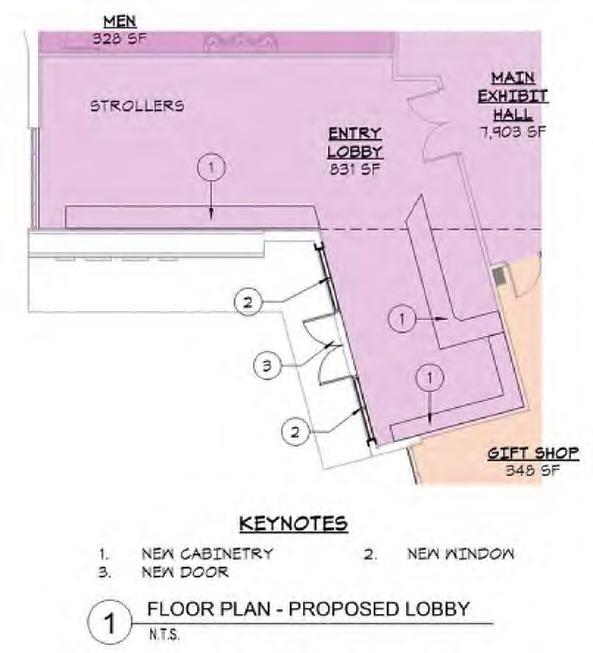
6. New Entry
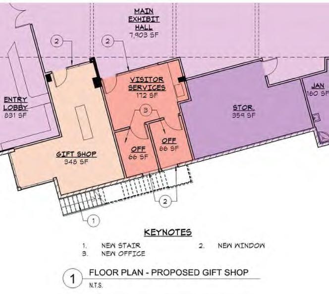
Open and clarify interior entry hall by removing existing service and storage zones along south wall of gallery. Create a space for tickets, orientation, gift + snack kiosks with access to changing exhibits and direct connection to each gallery space to the north.
• Remove obstructive structural elements as budget allows.
• Increase visibility to streetscape, Exhibit Hall and Artville spaces.
• Unify circulation along singular spline, and one continuous ceiling.
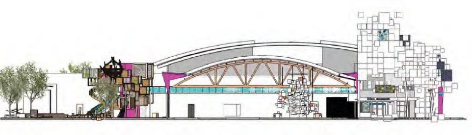
7. Main Exhibition Hall
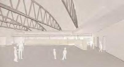
Centerpiece of renovation: open structure and increased ceiling heights celebrate original building architecture and create a ‘wow’ factor at entry. Texture at ceilings in gallery inspire creativity, experimentation and gathering.
• Expression of original structure, converging geometries, & textures.
• New MEP Systems to tie in with CoM Downtown Chiller Plant.
• New, low profile ‘Learning Wall’ separates busy entry, provides storage, while organizing pedestrian traffic within building.
8.
New Cafe
Create new meal prep-ready zone at northwest corner of building with access to outdoor sidewalks and courtyard picnic zones and main exhibit hall.
• Increase capacity for both staff functions and revenue generation
• Provide public visibility to the street with new glazing.
• Expand footprint with outdoor connections to Atrium.
9. Mobile Gift Shop Kiosks (in lieu of Gift Shop)
Generous 24’-0” corridors at New Entry provide opportunity for movable and changeable kiosks to serve evolving retail needs. Space is provided along south side of corridor in new scheme for direct access to visitors.
10. Second Floor Exhibit and Rental Space
Renovate spaces previously occupied by staff offices to create open, flexible program space for gatherings, meetings, and exhibits. Reserve northern zone adjacent to exterior stair - (accessible to new offices) - for staff library/ workroom.
II. PROJECT PRIORITIES | Future
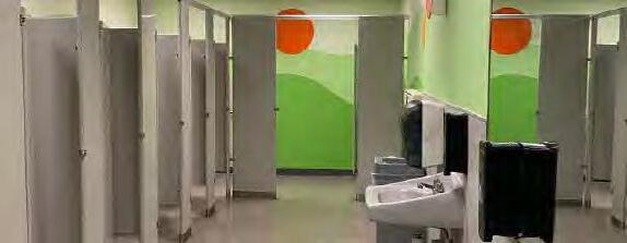
11. Main Exhibition Restroom + Support Upgrades
Modify existing restrooms for improved visitor flow and access, along with upgrades to existing fixtures and finishes and new drinking fountains.
12. Artville 1 Restroom + Classroom Upgrades
Modify existing restrooms for improved visitor flow and access, along with upgrades to existing fixtures and finishes and new drinking fountains.
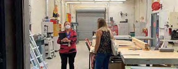
13. Fabrication Lab Upgrades
Provide daylight to shop with additional window openings at north wall for views from students arriving at north drop off zones to exhibits in progress.
14. West Entry (Site + Canopy) Upgrades
Establish easy-to-navigate, highly visible outdoor entry zone with accommodations for new beacon, shade and landscaping to create courtyard atmosphere at Pepper and Robson and windows into Entry Exhibit Hall.
15. Cafe (Site + Canopy) Upgrades
Provide new opening along west side of museum to create sidewalk cafe zone and west garden entry. Vews into space both day and night to activate street and invite community. Expand reach of cafe to public as available.
16. Cafe Expansion
Create new cafe destination for children and families with possibilities for service both during and after museum hours. Use space for revenue generation and special events. Accessible from inside and outside of Exhibit Hall as required.
17. Administration Courtyard
Use Texture Trails gallery as catalyst to for full back courtyard renovation with landscape, hardscape, shade devices for staff gathering/workzonesseparated by operable low height gate - opened for full special occasions.
18. Trash Enclosure Modifications
Reduce existing footprint at trash enclosures commensurate with museum needs, resolve geometry at curb and enclosure for more efficient use of courtyard space.
19. East Site Upgrades
Complete sidewalk improvements and exterior space for Artville 1 opening.
20. Pepper Place Sidewalk Expansion
Expand sidewalk for safety and shade at northwest side of Pepper to Robson.
II. PROJECT PRIORITIES
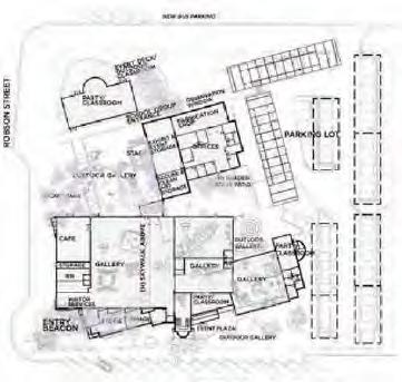
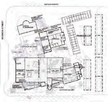
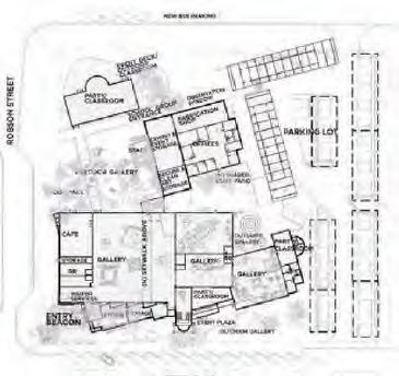
III. PROPOSED PLAN |
Reveal Existing Concealed Structural Elements
Highlight Materials + Textures of Original Building
Remove Column Obstructions + Blocked Views
Clear Away Partitions in Favor of Open Spaces
Provide Perimeter Storage Zones Throughout
Create Single, Programmable Circulation Spline
Upgrade + Provide Direct Access to MEP Systems
Expand Exhibit Footprint with Indoor/Outdoor Connections
Ensure Accessibility for All Sizes and Ages
Create Additional Revenue Generating Spaces
Create Spatious Entry Sequence
Unify and Improve Staff Zones
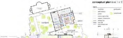
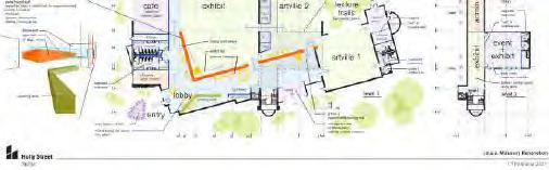
III. PROPOSED PLAN | Design Concept
IV. SQUARE FOOTAGES | Summary and
Existing
B
B
B
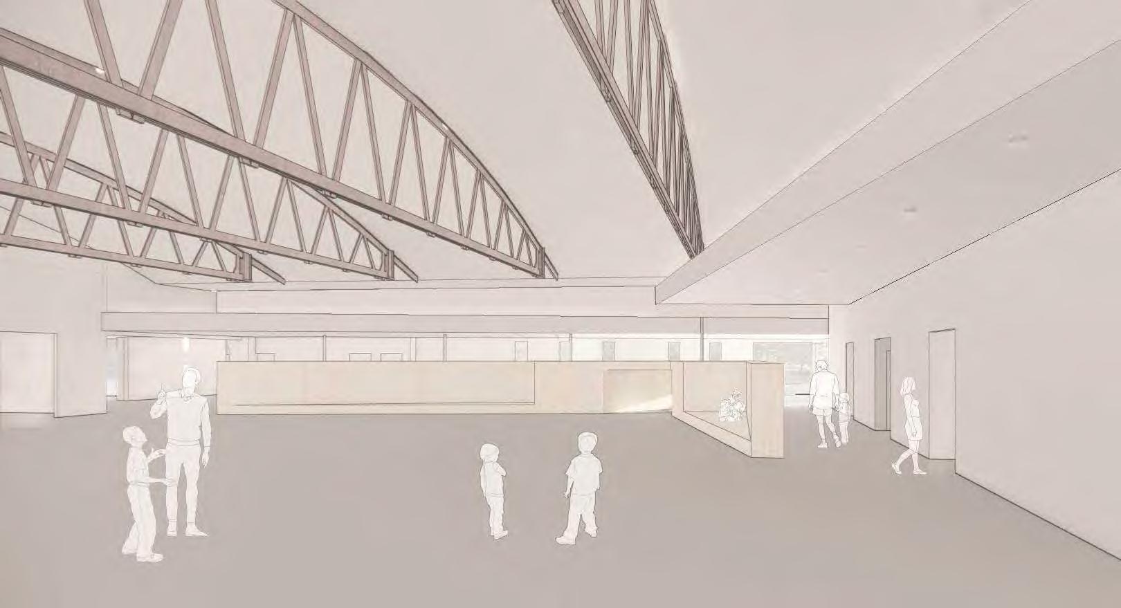
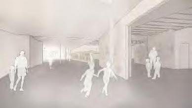
V. CONCEPTUAL VIEWS
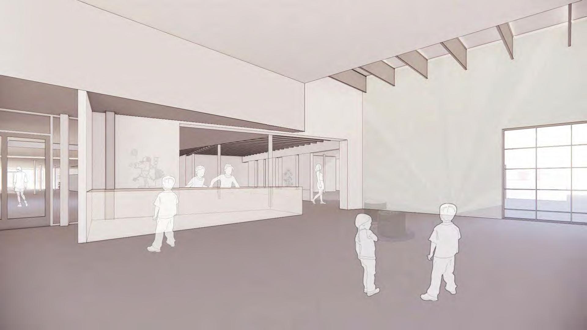
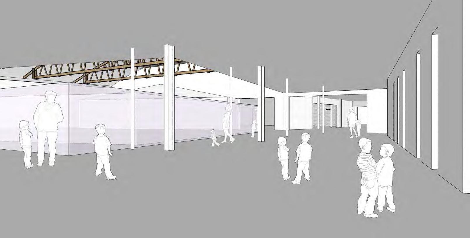
NEW ENTRY LOOKING EAST (Priority Two)
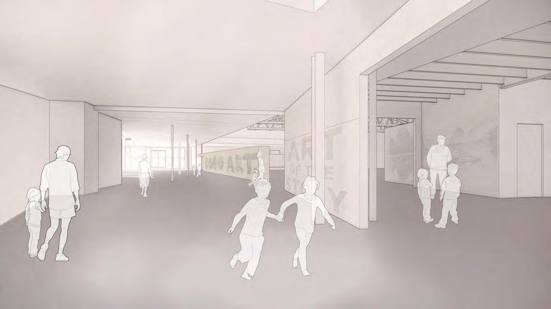
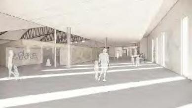
V. CONCEPTUAL VIEWS
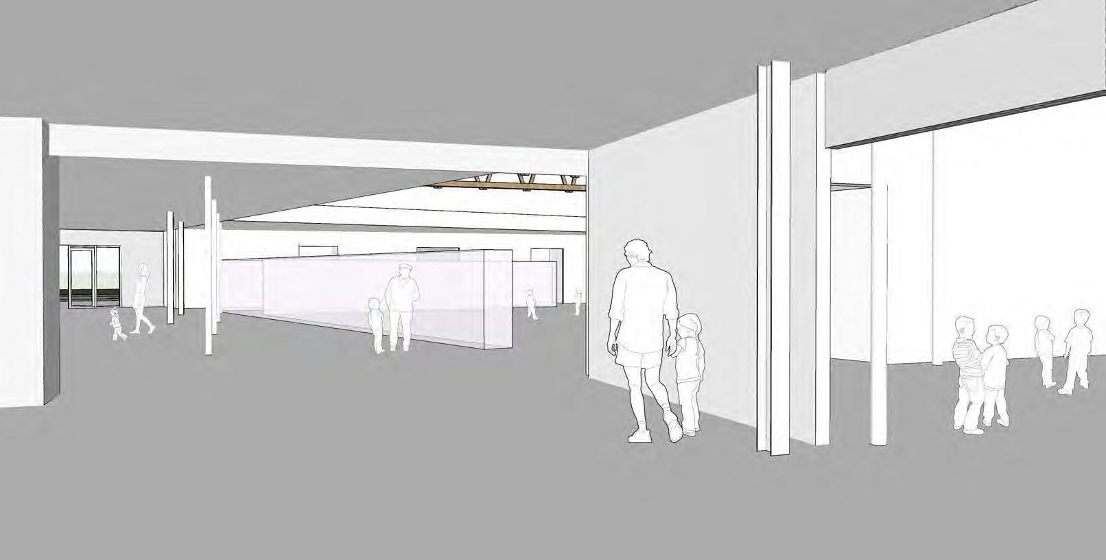
EXHIBIT HALL LOOKING WEST TO NEW ENTRY (Priority Two)
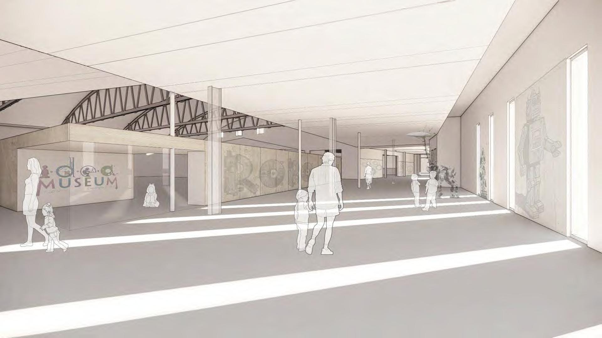
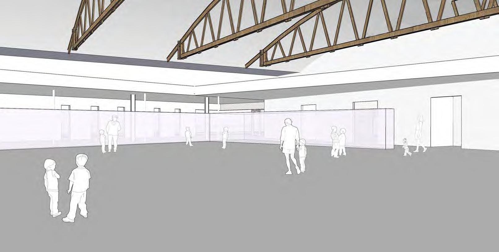
V. CONCEPTUAL VIEWS
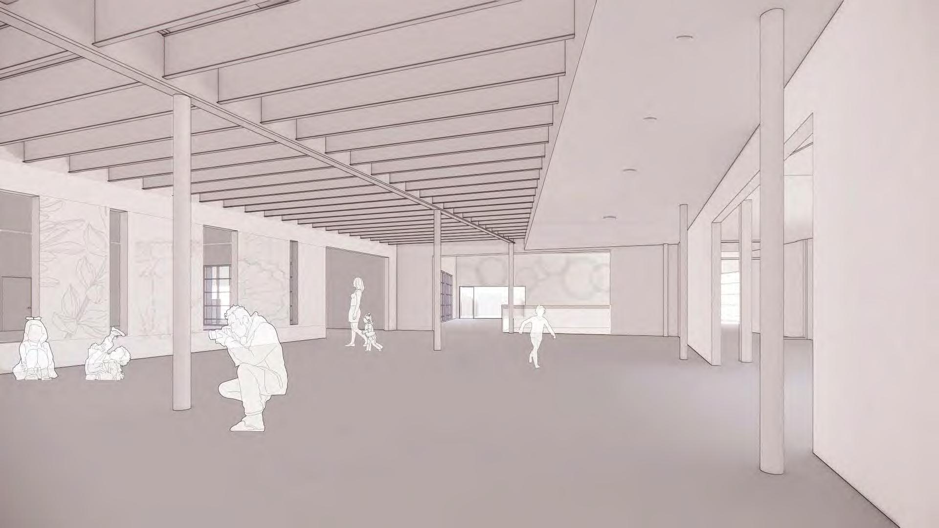
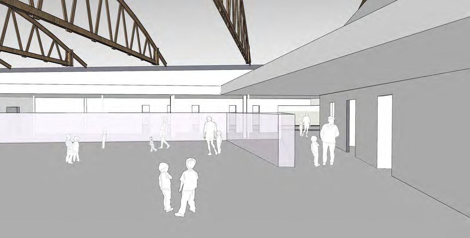
MAIN EXHIBITION LOOKING SOUTH (Priority Two)
V. CONCEPTUAL VIEWS
Schematic Design Report
ARTVILLE ONE LOOKING INTO ARTVILLE TWO (Priority One)
V. CONCEPTUAL VIEWS
ARTVILLE TWO LOOKING INTO ARTVILLE ONE (Priority One)
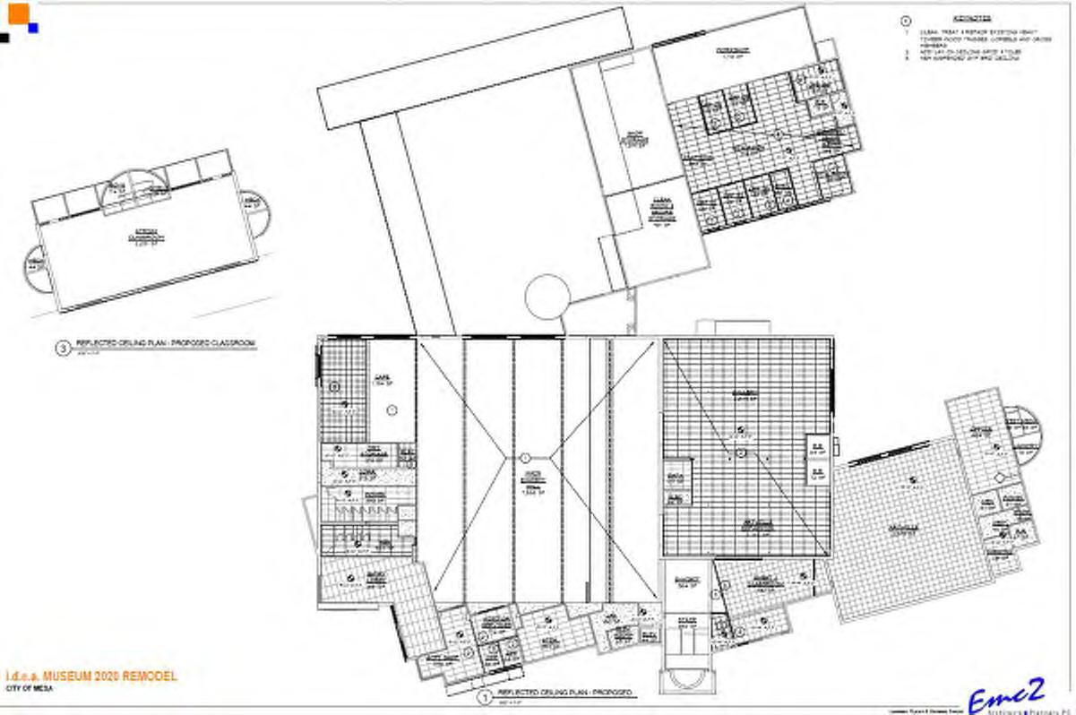
VI. SCHEMATIC DESIGN DOCUMENTS
VI. SCHEMATIC DESIGN DOCUMENTS (15%)
1.All
2.Do
3.Verify
5.Notify
6.Details,
7.All
11.All
VI. SCHEMATIC DESIGN DOCUMENTS
VI. SCHEMATIC DESIGN DOCUMENTS (15%)
VI. SCHEMATIC DESIGN DOCUMENTS (15%)
AVGAVERAGE
B&BBALLED AND BURLAPPED
BFBOTTOM OF FOOTING
BLDGBUILDING
BMBENCHMARK
BCBACK OF CURB
BOSBOTTOM OF SLOPE
BRBOTTOM OF RAMP
BRGBEARING
BSBOTTOM OF STEP/STAIR
BWBOTTOM OF WALL
CALCALIPER
C.B.CATCH BASIN
CFCUBIC FEET
CIPCAST-IN-PLACE
CJCONTROL JOINT
CLCENTERLINE
CLRCLEAR(ANCE)
C.O.CLEAN OUT COLCOLUMN
CONCCONCRETE CONTCONTINUOUS CUCUBIC DEGDEGREE
DEMODEMOLISH, DEMOLITION
DLDRAIN INLET
DIADIAMETER DIMDIMENSION DNDOWN DPDRAIN PANEL
JTJOINT LOWLIMIT OF WORK LPLOWPOINT MAXMAXIMUM MHMANHOLE MINMINIMUM MISCMISCELLANEOUS MTDMOUNTED MTLMETAL NICNOT IN CONTRACT
NOMNOMINAL
NTSNOT TO SCALE
OCON CENTER(S)
ODOUTSIDE DIAMETER
OPPOPPOSITE PCPOINT OF CURVATURE
PEDPEDESTRIAN PERFPERFORATED
PIPOINT OF INTERSECTION PLPROPERTY LINE PTPOINT OF TANGENCY PVMTPAVEMENT PVRPAVER(S) QTYQUANTITY RRADIUS RDROOF DRAIN REREFERENCE REINFREINFORCE(D), (ING)
REQ'DREQUIRED REVREVISION(S), REVISED RIMRIM ELEVATION ROWRIGHT OF WAY SANSANITARY SCHSCHEDULE SDSTORM DRAIN SECSECTION SFSQUARE FOOT (FEET)
FCFACE OF CURB FGFINISH GRADE FLFLOWLINE FOSFACE OF STEP R RADIUS FOWFACE OF WALL
FSFINISHED SURFACE
FTFOOT (FEET)
FTGFOOTING
GAGAUGE
GALVGALVANIZED
GBGRADE BREAK
GCGENERAL CONTRACT(OR)
GPMGALLON PER MINUTE
HORIZHORIZONTAL HPHIGH POINT HTHEIGHT IDINSIDE ININCHES IEINVERT
VI. SCHEMATIC DESIGN DOCUMENTS (15%)
VI. SCHEMATIC DESIGN DOCUMENTS (15%)
VI. SCHEMATIC DESIGN DOCUMENTS (15%)
DEMOLITION NOTES
VI. SCHEMATIC DESIGN DOCUMENTS (15%)
DEMOLITION NOTES
NOTES
1.CONTRACTOR
CONTACT LANDSCAPE ARCHITECT IF PROTECT IN PLACE TREES ARE IN CONFLICT WITH HARDSCAPE LAYOUT AND CONSTRUCTION.
4.ALL EXISTING IRRIGATION TO EXISTING TREES SHALL REMAIN FUNCTIONAL THROUGH CONSTRUCTION.
VI. SCHEMATIC DESIGN DOCUMENTS (15%)
DEMOLITION NOTES
59RUELLIA BRITTONIANA `BLANCA` 1 GAL BLANCA RUELLIA 12SALVIA CLEVELANDII 15 GAL CLEVELAND SAGE
NOTES
VI. SCHEMATIC DESIGN DOCUMENTS (15%)
SCHEDULE
MULTIRADIATA 1 GAL DESERT MARIGOLD 369BOUTELOUA GRACILIS `BLONDE AMBITION`1 GAL BLONDE AMBITION BLUE GRAMA 96ENCELIA FARINOSA 5 GAL BRITTLE BUSH
MEXICO PRICKLYPEAR
GAURA LINDHEIMERI 5 GAL GAURA
22OPUNTIA GOMEI `OLD MEXICO` 15 GAL OLD MEXICO PRICKLYPEAR
29PENSTEMON EATONII 5 GAL FIRECRACKER PENSTEMON
29PENSTEMON EATONII 5 GAL FIRECRACKER PENSTEMON
87PENSTEMON PARRYI 5 GAL PARRY`S BEARDTONGUE
GAL FIRECRACKER PENSTEMON
87PENSTEMON PARRYI 5 GAL PARRY`S BEARDTONGUE
11PHYLLOSTACHYS AUREA 15 GAL GOLDEN BAMBOO
87PENSTEMON PARRYI 5 GAL PARRY`S BEARDTONGUE
11PHYLLOSTACHYS AUREA 15 GAL GOLDEN BAMBOO
11PHYLLOSTACHYS AUREA 15 GAL GOLDEN BAMBOO
59RUELLIA BRITTONIANA `BLANCA`
59RUELLIA BRITTONIANA `BLANCA` 1 GAL BLANCA RUELLIA
12SALVIA CLEVELANDII 15 GAL CLEVELAND SAGE
DEMOLITION NOTES
31SALVIA GREGGII 5 GAL AUTUMN SAGE
59RUELLIA BRITTONIANA `BLANCA` 1 GAL BLANCA RUELLIA 12SALVIA CLEVELANDII 15 GAL CLEVELAND SAGE 31SALVIA GREGGII 5 GAL AUTUMN SAGE 63SPHAERALCEA AMBIGUA 5 GAL DESERT GLOBEMALLOW
COVERS QTY BOTANICAL COMMON
63SPHAERALCEA AMBIGUA 5 GAL DESERT GLOBEMALLOW
GROUND COVERSQTYBOTANICAL / COMMON NAME
ARCHITECT IF PROTECT IN PLACE TREES ARE IN CONFLICT WITH HARDSCAPE LAYOUT AND CONSTRUCTION.
4.ALL EXISTING IRRIGATION TO EXISTING TREES SHALL REMAIN FUNCTIONAL THROUGH CONSTRUCTION.
2,451 SFTURF GRASS SOD
VI. SCHEMATIC DESIGN DOCUMENTS (15%)
VI. SCHEMATIC DESIGN DOCUMENTS (15%)
d2d3
VI. SCHEMATIC DESIGN DOCUMENTS (15%)
VI. SCHEMATIC DESIGN DOCUMENTS (15%)
VI. SCHEMATIC DESIGN DOCUMENTS (15%)
VI. SCHEMATIC DESIGN DOCUMENTS (15%)
VI. SCHEMATIC DESIGN DOCUMENTS (15%)
VI. SCHEMATIC DESIGN DOCUMENTS (15%)
VI. SCHEMATIC DESIGN DOCUMENTS (15%)
VI. SCHEMATIC DESIGN DOCUMENTS (15%)
VI. SCHEMATIC DESIGN DOCUMENTS (15%)
VI. SCHEMATIC DESIGN DOCUMENTS (15%)
VI. SCHEMATIC DESIGN DOCUMENTS (15%)
VII. ENGINEERING NARRATIVES
GENERAL
The purpose of the assessment is to evaluate the condition of the existing mechanical, plumbing and electrical systems and determine what modifications and replacement will be necessary to accommodate the proposed new usages.
This initial 15% design narrative describes the MPE requirements for renovation of key areas and phasing options.
The project will repurpose existing spaces within the existing museum and former Bashas Grocery store, located at 150 W. Pepper Place, Mesa, AZ 85201 to create new galleries, interactive public spaces, new offices, and a relocation of the museum entrance.
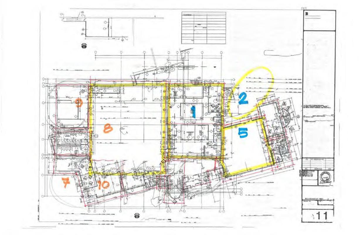
Areas included in the scope:
1. Zone 1 Existing Exhibit Space (1.19 Exhibit)
2. Zone 2 New Gallery (1.15 Artville) Expansion
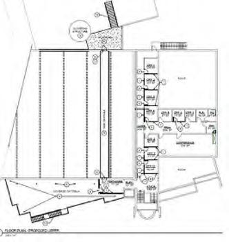
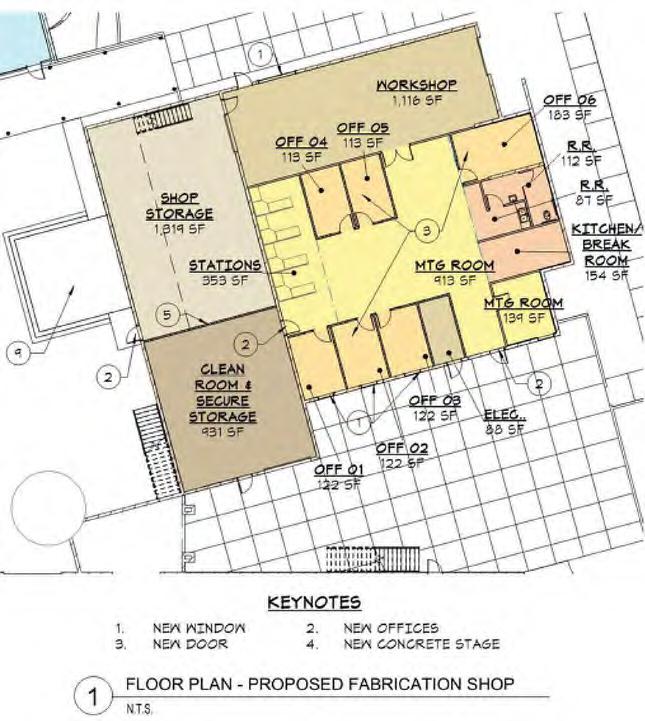
3. Zone 5 Fabrication Shop
4. Second Floor Offices
Areas included in future scope:
1. Zones 3 and 4 East Gallery (Artville)
Refer to the proposed new Architectural Drawings and Diagrams for specific locations and details regarding the location and new usage of each of these spaces.
The mechanical electrical and plumbing systems analysis is based on site walks, meetings, and review of existing MPE drawings. The objective is that these narratives will accomplish the following:
• Communicate proposed design concepts.
• Enable order of magnitude estimates of probable construction costs.
• Identify issues to be addressed in the development of the systems designs.
The building systems designs will comply with applicable 2018 International Codes with City of Mesa Amendments, and the 2017 National Electrical Code.
MECHANICAL
Existing Conditions:
• Chilled water is delivered to the building from the City of Mesa District Cooling system. Chilled water mains extend from the district mains in First Street to the building. These lines rise up on the north side of the building and route across the roof above the fabrication shop to the courtyard between main exhibit area and the fabrication shop. The chilled water piping connects to an existing air cooled chiller mounted on a mezzanine above the courtyard.
• The existing air cooled chiller is no longer operable so the shell and tube heat exchanger in the air cooled chiller has been converted to a chilled water heat exchanger and this heat exchanger is used to decouple the building from the District Cooling System.
• Chilled water pumps are installed on the mezzanine to provide chilled water flow to the building.
• A gas fired heating hot water boiler and circulating pump are also mounted on the mezzanine. Heating hot water piping extends to the air handling unit, fan coil units and the VAV boxes.
• A Variable Air Volume chilled water air handling unit is also mounted on the mezzanine. This unit provides cooling and outside air to the main exhibit area and lobby.
• Building chilled water piping also extends to four fan coil units located in the fabrication shop.
VII. ENGINEERING NARRATIVES
• There are two split system heat pump units serving the existing classroom building. Vertical air handling units are located in fan rooms and air cooled condensing units are located in small exterior mechanical yards.
• The rest of the building is conditioned using packaged rooftop heat pump units.
General:
• Refer to the attached mechanical sketch sheet M1.00.
• The air cooled chiller is no longer operable and should be removed and replaced with a new plate and frame heat exchanger.
• The new plate and frame heat exchanger must comply with City of Mesa standards.
• The new heat exchanger will need to be insulated and jacketed with aluminum jacketing to prevent condensation and to protect the insulation from damage.
• It is recommended that the heat exchanger be mounted inside the building to protect it from the elements, proposed location is on the mezzanine in the storage area.
• The new heat exchanger should be sized to accommodate the total cooling load for the entire building so that as rooftop units fail, they can be replaced with chilled water air handling units.
• New chilled water pumps, valves, and controls should be provided with the new heat exchanger.
• The existing air handling unit serving the exhibit hall is in need of repair. At a minimum, duct insulation should be replaced and the coils and drain pan should be cleaned.
• Currently the packaged units and split systems are controlled with wall mounted programmable thermostats. A City of Mesa standard Trane Building Automation System should be installed in this building to control the heat exchanger, boiler, pumps, air handling unit and all new and existing equipment.
Zone 1 Existing Exhibit Space (1.19 Exhibit)
• It will be necessary to modify the existing ductwork and air distribution to accommodate the new floor plan and ceiling revisions. The existing VAV boxes, heating hot water piping and medium pressure educt mains are to remain.
• The toilet exhaust fans and associated ductwork are to be replaced.
• Future: There is consideration or removing the ceiling in this area in the future to provide exposed structure. If this is to be accomplished, it will be necessary to provide new medium pressure duct mains, new heating hot water piping and all new VAV boxes which will need to be located above the new storage room with new exposed spiral low pressure duct mains routed through the webs of the roof trusses with round air distribution devices.
Zone 2 New Gallery (1.15 Artville) Expansion
• The area which will become the New Gallery (Artville) is served by a nominal 10-ton packaged rooftop unit with gas heat. This unit serves the area to become the new lobby as well.
• This area will be converted to an open floor plan area. This unit will probably not be adequate to serve the new use.
• It will be necessary to replace this unit during the renovation.
• The existing unit should be replaced with a new chilled water air handling unit.
• The unit could be VAV with VAV boxes with electric heat or Constant Volume with hot water heating coil to serve the new occupancy.
• Chilled water (and possibly heating hot water piping) will need to be extended from the heat exchanger and boiler to this new location. This piping should be sized to accommodate the East Gallery in the future as well.
• The air handling unit should have a 100% outside air economizer for free cooling when outside conditions are favorable. A gravity hood with motorized dampers should be installed for building relief and to maintain the building at a positive pressure relationship with respect to outside.
• The existing supply and return air ductwork and air distribution devices will need to be replaced to accommodate the new floor plan layout in these areas.
• The new ductwork and air distribution will need to be coordinated with the new ceilings and lighting to provide an integrated solution.
• The new air handling unit will need to be interfaced with the Building Automation System for control and monitoring.
ENERGY SYSTEMS DESIGN, INC.
SCHEMATIC DESIGN NARRATIVE
Zones 3 and 4 East Gallery (Artville) (Future Scope)
• The area which will become the East Gallery (Artville) is served by a nominal 17 ½-ton packaged rooftop unit with gas heat.
• The existing unit should be adequate to serve the new use. The unit should be replaced in the future with a VAV chilled water unit with VAV boxes with electric or hot water heat.
• It will be necessary to modify the existing supply and return air ductwork and add new air distribution devices to accommodate the new floor plan layout in these areas.
• The new ductwork and air distribution will need to be coordinated with the new ceilings and lighting to provide an integrated solution.
Zone 5 Fabrication Shop
• The fabrication shop is conditioned with a nominal 10-ton packaged rooftop unit. This unit serves the wood workshop shop as well.
• When the fabrication shop is converted to office space, it will be necessary to separate the office space from the wood workshop and provide separate temperature zones.
• The existing packaged rooftop unit should be removed and replaced with a new Variable Air Volume chilled water air handling unit. New medium pressure supply air ductwork should be extended to the new office areas. VAV boxes with electric heat or hot water heat should be installed to provide zone control of the offices.
• The air handling unit should have a 100% outside air economizer for free cooling when outside conditions are favorable. A gravity hood with motorized dampers should be installed for building relief and to maintain the building at a positive pressure relationship with respect to outside.
• The warehouse shop is conditioned by four fan coil units with chilled water coils and heating hot water coils. There are also evap coolers installed on the roof above this space but they appear to have been abandoned.
• A portion of the warehouse is to be converted to office space. This area should be connected to the new VAV air handling unit.
• One or two of the existing fan coil units serving the warehouse could be repurposed to serve the workshop or a new chilled water fan coil unit could be provided as appropriate.
• All new equipment will need to be interfaced with the Building Automation System for control and monitoring.
Second Floor Offices
• The second floor offices are to be modified into an exhibit area, an administration area and a party room/exhibit space. This area is currently served by a single nominal 7 1/2-ton packaged rooftop unit with gas heat.
• The existing Library space on the south end is hot in the summer.
• This unit is not adequate to serve the new use.
• The party room/exhibit space, administration area and the exhibit area should be provided with new mechanical systems. The chilled water piping at the mezzanine is just outside this area to the north. We would recommend extending chilled water piping into this area and providing new chilled water fan coil units to serve these spaces.
• Each space should get a separate unit to provide zone temperature control.
• Heating hot water piping could also be extended to this are and the new units could have hot water heating coils or the new units could be provided with electric heating coils.
• Outside air should be ducted to wall louvers or gravity hoods.
• This area will require all new ceilings and therefor all new air distribution.
• New temperature sensors and control valves will be necessary to control the new units.
• The new and existing units should be interfaced with the Building Automation System for Control and Monitoring.
VII. ENGINEERING NARRATIVES
VII. ENGINEERING NARRATIVES
Existing Main Distribution System:
A. The building is proved utility power from a City of Mesa Electric utility transformer that supplies power to an existing 1200A, 480/277V, 3-phase, 4-wire Service Entrance Section (SES) located outside the building. The SES and associated circuit breakers and distribution equipment are circa. 2002. Per industry standards, average useful life for well-maintained equipment is 35 years and 17 years for unmaintained. At 19 years old the building electrical distribution equipment appears to be within its life cycle and may remain in place and operational.
Branch Distribution System:
1. The service feeds a series of 480/277V distribution equipment, transformers, and 208/120V, 3-phase, 4wire panelboards that supply lighting, mechanical, HVAC and receptacle loads throughout the space. Existing distribution, switchboards, panelb oards and transformers also appear to be in adequate condition and may remain and be reused for new work.
Lighting Fixtures:
1. Entire building using a combination of 2x4 troffers, recessed downlights, track lights, directional lights, strip lights, and low bays. There is a mix of Fluorescent, incandescent and LED lamps. All new light fixture will utilize LED lamps.
2. Some public areas where the touching of surfaces occurs the most may get fixtures with germicidal lamps.
Lighting controls:
1. Existing lighting controls are a combination of manual switching in the office and utility areas and a Lutron LCP128 Dimming and Switching System that controls the museum exhibit galleries. The existing lighting control system will need to be upgraded with a combination of 1) Automatic daylighting controls – the lights must dim automatically in relation to the amount of daylight entering through windows. 2) Occupant/vacancy sensing controls – the lights must automatically turn off no people in the room. 3) Dimming control. At this time, we feel the lighting control panel that controls the exhibit lights can remain and be reused.
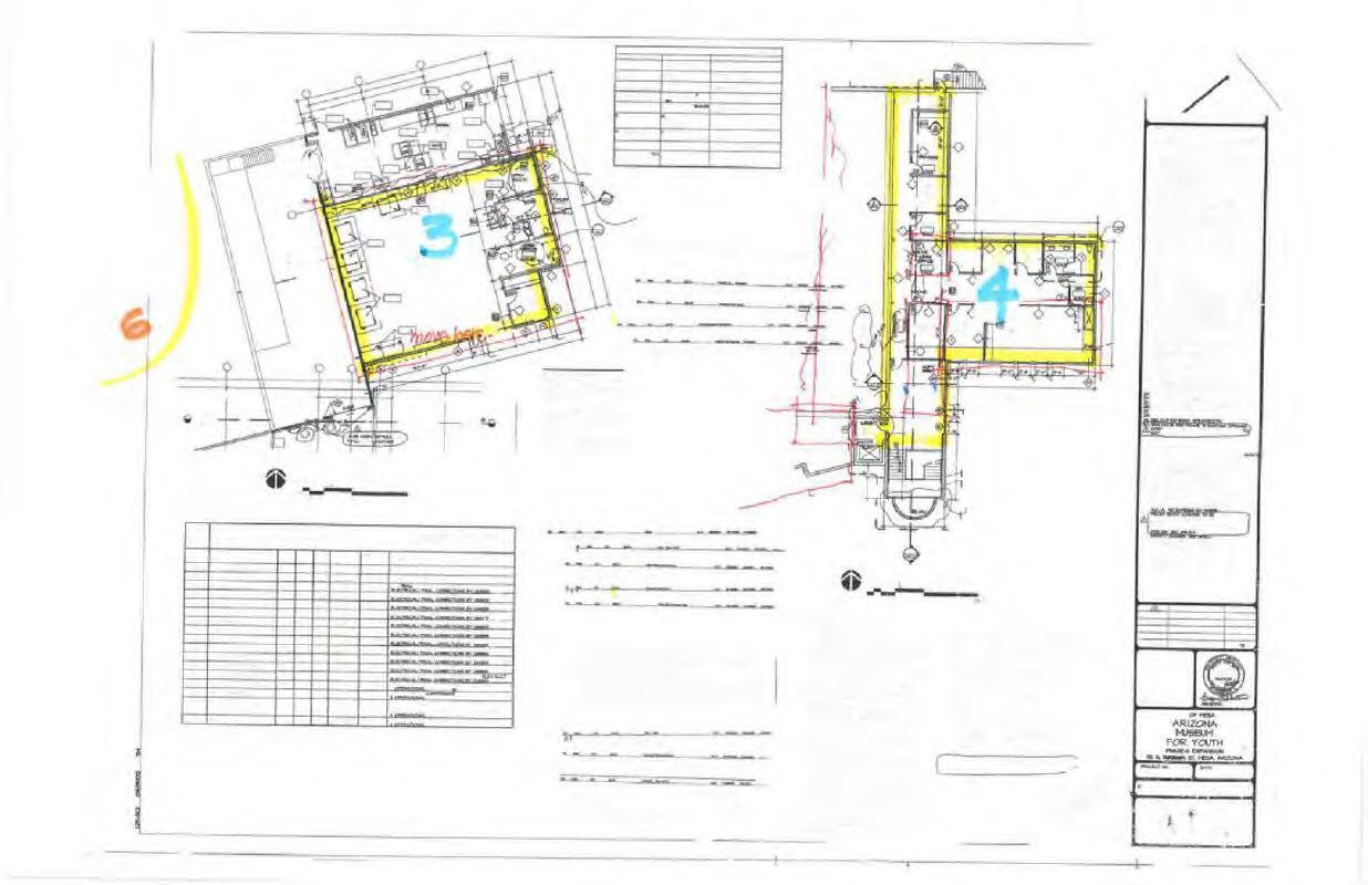
Exhibit & Main Electrical Room (Future Scope)
• The main electrical room located to the north west of the main building is scheduled to be demolished. All existing electrical equipment in this room will require relocation to new Storage Room 1.16. Equipment is as follows: Panels ‘AC’, ‘A’, ‘C’, ‘C2’, Lutron Lighting Control Panel, Lighting panel, and all dimming switchbanks. All existing feeder conduits and conductors will need to be intercepted and extended to new location, either by trenching slab or routed overhead. All branch circuits will need to be reconnected to panels. All lighting control wiring will be reconnected to the 20+ dimmer switches and lighting control panel.
• Relocation of electrical room panelboards and lighting control panel shall be as a phased/future scope.
• New LED light fixtures will be required along with updated lighting controls.
• New floor boxes for power and possibly data/communication outlets will be required for exhibits. Saw cutting of existing slab, or above slab raceway concealed by flooring will be required for new wiring and cabling. The 2 main options are 1) an in-slab flush to grad system such as Legrand Walker Duct which would require many feet of saw cutting concrete, or 2) a raised floor system such as FreeAxez raised floor system.
• New HVAC unit will require a new disconnect and power connection.
New Gallery (1.15 Artville 2) Expansion
• Most of this area will be converted to an open floor plan area. Only the I.T Room and Fire Alarm Room are to remain.
• Two 208/120V electrical panels (panels ‘P3’ and ‘P4’) located on a wall scheduled for demolition will need to be relocated.
• The proposed new location for existing panels ‘P3’ and ‘P4’ shall be in the new 1.16 Storage Room.
• New LED light fixtures will be required along with updated lighting controls.
• New floor boxes for power and possibly data/communication outlets will be required for exhibits. Saw cutting of existing slab, or above slab raceway concealed by flooring will be required for new wiring and cabling.
• New HVAC unit will require a new disconnect and power connection.
East Gallery (1.15 Artville 1)
• Most of this area will be converted to an open floor plan area. Only the 2 restrooms, laundry room and mechanical room to remain.
• Existing 208/120V panels ‘P1’ and ‘P2’ are to remain in place on the east block wall. Since these panels are open to public view, a new electrical closet is to be built around these panels.
• New LED light fixtures will be required along with updated lighting controls.
• New floor boxes for power and possibly data/communication outlets will be required for exhibits. Saw cutting of existing slab, or above slab raceway concealed by flooring will be required for new wiring and cabling.
• New HVAC unit will require a new disconnect and power connection.
Fabrication Shop
• The fabrication shop is to be converted to office space. Since new offices will be built on the south wall, the existing electrical equipment located in this area will need to be relocated. This electrical equipment includes an existing 480/277V, 3ph panel ‘HSH’, transformer ‘TXLSH’, and two 208/120V, 3ph panels ‘LSH1’ and ‘LSH2’ that feeds the tools, receptacles, lights and HVAC in the area. All distribution equipment will be relocated to the Warehouse area. All existing conduit and conductors shall be extended to the new equipment locations for reconnection.
• The existing paint booth is being removed including the exhaust, as well as some fabrication tools. This should free up some capacity in the existing panel for new office lighting, receptacle and HVAC loads.
Second Floor Offices
• The second floor offices are to be modified into an exhibit area, an administration area and a party room/exhibit space. This area is currently served by an existing Panel ‘P5’ (100A, 208/120V, 3ph).
• Depending on the electrical requirements of the new spaces, this existing second floor panel may need to increase in size.
• This area will require all new ceilings and therefor all new light fixtures and controls.
• Additional power will be required for the new HVAC units.
Courtyard area between the main building and I.D.E.A Bldg. 3
• An existing electrical wireway and metal enclosure housing receptacles and control transformers is located just to the east of the exit door located on the north west corner of the main building. The wall this electrical equipment is mounted to is scheduled to be demolished. The existing equipment and associated wiring to be relocated to the west of the new doorway.
• It is recommended the Museum evaluates the functionality of this existing equipment at this time and possibly update this outdoor lighting setup.
Recommendation:
ESD has determined that the existing 1200A 480/277V service has adequate capacity for this new work and can remain in place and operational. Relocating panels will require extending existing feeders and
SYSTEMS DESIGN, INC.
VII. ENGINEERING NARRATIVES
Existing 1200A, 480/277V, 3PH Service Entrance Section Existing Lighting Control Panel to
Courtyard outlets & control transformers to be relocated
VII. ENGINEERING NARRATIVES
PLUMBING SYSTEMS
Plumbing modifications include:
• Upgrading the existing restrooms at the new entrance
• Upgrading the existing restrooms at the East Gallery
• Upgrading the existing restrooms at the second floor party room/event space
• Upgrading the existing restrooms at the fabrication shop
The existing backbone plumbing systems should be adequate to serve the modifications.
Sanitary Building Drain and Vent:
Sanitary drain piping from all fixtures will extend below floor slab and connect to existing sanitary building drain. New piping for sanitary drain piping below slab is proposed to be cast iron piping with hub-less couplings and fittings. SCH 40 Solid wall PVC can be considered for below slab drainage. Above floor piping is proposed to be cast-iron piping with hub-less fittings.
Sanitary vent piping will connect to all fixtures and collect above ceiling and overhead and extend through the roof in multiple locations or connect to existing where adequate.
Rainwater:
Existing roof drains and piping is to remain.
Domestic Water Distribution:
Domestic cold-water piping will be extended as required to the renovated restrooms. Domestic cold-water piping will be Type L copper with wrought solder fittings and joints.
Valves and Devices:
All branch mains and cold-water lines serving groups of fixtures and separate areas will be provided with isolation valves.
Hot Water Systems:
Restrooms:
Existing hot water piping will be extended to new fixtures as required. Hot water will be circulated in accordance with IECC requirements and to ensure prompt hot water delivery to lavatories.
Plumbing Fixtures:
Fixtures will be of high efficiency commercial grade fixtures.
G Monte Sturdevant, P.E. Matthew Klem CPD Andy Nathal President Senior Plumbing Designer Senior Electrical Designer
7135 E. Camelback Rd. Suite 275 Scottsdale, Arizona 85251 480.481.4900 ENERGY SYSTEMS DESIGN, INC.
VII. ENGINEERING NARRATIVES
1440 E Missouri Ave Suite C195
Phoenix, AZ 85014
p.602.888.0336
www.pangolinstr.com
I.D.E.A. MUSEUM STRUCTURAL NARRATIVE JUNE4,2021
DESCRIPTION
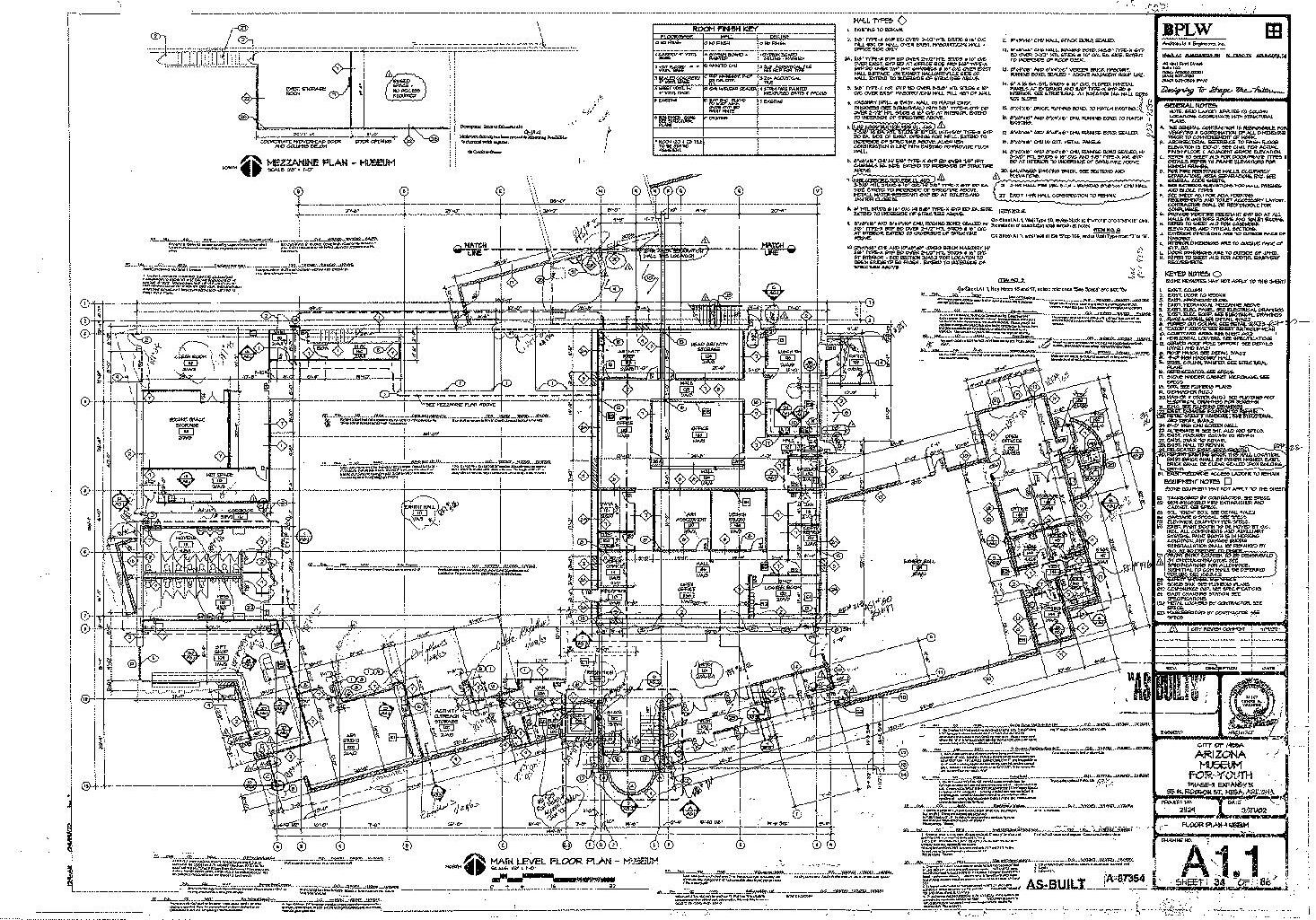
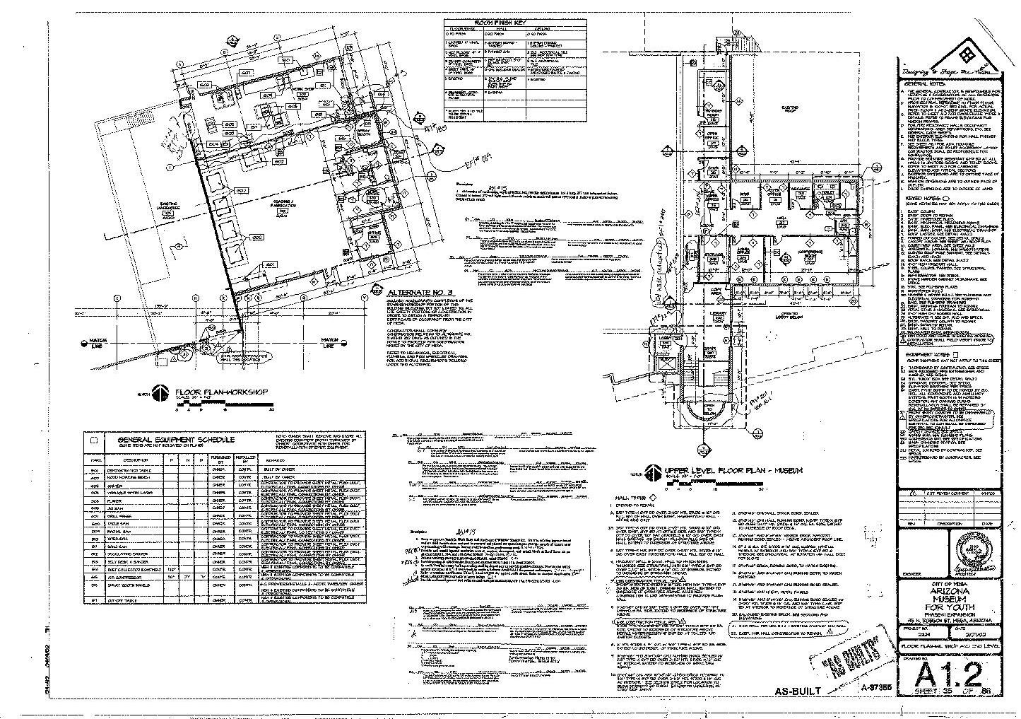
The i.d.e.a. Museum at 35 N. Robson St. in Mesa, Arizona consists of a single-story 1950’s era building functioning as the main exhibit hall space of a children’s museum. The building underwent a major addition and expansion in 1995 which include an adjoining single-story warehouse building and a separate single-story classroom building. In 2002, another major expansion occurred which included a single-story addition south of the main exhibit hall, a single-story east expansion for additional exhibit/activity space and a central ‘spine’ that included a two-story office/administrative space.
The original 1950’s building structure consists of curved wood trusses at approximately 17 feet on-center with wood purlins spanning between trusses. The trusses and roof structure bears on perimeter masonry walls and steel columns. The 1995 warehouse addition is constructed of wood TJI’s at 24” on-center bearing on masonry bearing walls. The structure of the 2002 additions are primarily steel deck on steel joists and steel beams spanning to a combination of steel beams and masonry walls (existing and new).
Existing structural drawings for the 1995 and 2002 additions/expansions have been provided by the Owner for review; however, the original building structural drawings were not provided.
We have completed the schematic design for the i.d.e.a. Museum renovation. We are providing foundation and framing plans showing the conceptual design for areas requiring modifications or additions to the existing structure as outlined below.
DEMOLITION
Demolition of the existing structure is minimal for this scope of work. Structural demolition is limited to new openings in existing masonry walls and sawcut and removal of existing slab-on-grade to provide for underground, concealed electrical and data. Please refer to architectural information regarding selective demolition related to main entry reconfiguration and removal/replacement of existing steel girders and removal of several steel columns
BUILDING PERIMETER (Base Scope)
The foundation plan shows several locations where portions of the existing perimeter masonry wall will be demolished to create new openings in the wall. To support the new openings, steel angle lintels will be added at these locations.
New glazed roll-up doors will be added at four locations around the perimeter of the building. New steel columns will be provided at the ends of the doors for support. HSS6x4x1/4 columns are called out on the schematic design plans. These sizes will need to be verified once roll-up door product data is available, as manufacturer specifications may require different dimensions. These columns bear on existing wall footings, which will need to be extended to account for the new concentrated loads under the columns. Required sizes are called out on the plans. New steel lintels will be required to support these new longer openings. Required wide flange beam sizes are called out on the framing plans.
Masonry wall infills are called out where required. Infills will be tied into existing masonry walls and footings with epoxy bars.
MAIN ENTRY FRAMING (Base Scope)
The main entry storefront configuration will be redesigned. To do so, portions of existing masonry walls and existing steel columns will be demolished. Four new steel columns will be added to support the new storefront. Three of these columns will bear on new footings, and one of them will bear on an existing wall footing that will need to be extended in order to meet the demand of the new concentrated load.
The new storefront configuration will require modifications to the roof framing above. Steel beams wil be added at locations where the demolished masonry walls were and support the existing steel joists. Some of the new beams will frame into existing joists. These joists have been evaluated and determined to be structurally adequate to support the additional point load from the new beams. Prior to demolition of the existing masonry walls, a site visit will be required to determine the bearing point of one of the joists in this area, as existing drawings do not clearly show which bearing wall the joist is supported by.
Two existing wide flange columns by the main entry will be removed. New roof beams will be required to support the existing joists based on the new spans. Existing wide flange columns and footings in this area have been evaluated and determined to be structurally adequate for the additional concentrated loads. A deeper analysis will be required in this area, as one of the beams affected by the column removal appears to be part of the lateral system (moment frame). A method to transfer the lateral loads in this area will need to be designed.
MAIN ENTRY CANOPY (Phased Scope)
A new steel canopy will be added to the new main entry to the museum. The canopy is framed using HSS members supporting a perforated metal deck per architectural. The canopy beams will be supported by two columns on the outside of the buildings, and the new steel structure supporting the new storefront at the main entry. Preliminary sizes for the beams and columns have been provided, but there is some flexibility with the dimensions and shapes (round vs square HSS) of the members in case a different architectural look is desired.
CAFÉ CANOPY (Phased Scope)
Per the provided backgrounds, there will be a new canopy built on the side of the café. The canopy is anticipated to be framed utilizing HSS members supporting perforated metal deck per architectural and shall be cantilevered from the existing building utilizing post-installed connection plates to the masonry wall.
ARTVILLE FRAMING (Phased Scope)
PANGOLIN
VII. ENGINEERING NARRATIVES
Per client’s request we evaluated the possibility of removing 4 columns in the Artville space. We recommend keeping these columns. All four of these columns are supporting girders from the second floor above. None of the existing supports would be able to support the additional loads if the requested columns were removed.
A portion of the masonry wall on grid 5, between grids S and V will be removed. Due to the bearing conditions above, a steel lintel will need to be added to support the wall above, with columns at each end of the beam. These columns will bear on existing wall footings, which will need to be extended to support the new concentrated loads.
BUILDING CODE
2018 International Building Code (IBC) and United Facilities Criteria (IFC) 3-301-01
VERTICAL LOADS
New construction:
Roof Dead Load = 20 psf
Roof Live Load = 20 psf (reducible)
2nd Floor Dead Load = 85 psf
2nd Floor Live Load (exhibit/event) = 100 psf
2nd Floor Live Load (office) = 50 psf
Mechanical room = 150 psf
LATERAL LOADS
Wind:
Basic Wind Speed = 102 mph
Exposure Category = C
Seismic:
Importance Factor = 1.0
Soils Site Class = D (default)
Spectral Response Coefficients:
SDS = 0.201
SD1 = 0.107
Seismic Design Category = B
Analysis Procedure: Equivalent Lateral Force Procedure
Lateral Force Resisting System: Intermediate Masonry Shear Walls (R=3.5)
MATERIAL PROPERTIES
Concrete: Walls = 4000 psi
Footings = 3,000 psi
Slabs on Grade = 4,000 psi
All other = 3,000 psi
LLC 1440 E Missouri Ave, Suite C195, Phoenix, AZ 85014 Page 3 of 4
For additional information regarding this narrative or the schematic design plans, feel free to reach out to us.
Prepared
By,
LUIS F. VALDEZ S., P.E. CRYSTAL E. BLANTON, S.E.
Project Engineer Principal / Managing Partner lvaldezsoto@pangolinstr.com cblanton@pangolinstr.com
STRUCTURAL LLC 1440 E Missouri Ave, Suite C195, Phoenix, AZ 85014 Page 4 of 4
PANGOLIN STRUCTURAL
PANGOLIN
VII. ENGINEERING NARRATIVES
I. Civil Narrative – Assessment of Existing Conditions
The i.d.e.a. Museum in Mesa is proposing improvements to multiple areas and exhibits within the existing facility. The project will include improvements to the Childhood Gallery, Childhood Garden, Artville Gallery, exhibits and landscape improvements at The Atrium, staff office renovation/relocation, and potentially improvements to the entry. The civil portion of the project will include assessment of the existing grading and drainage for the site and the impacts of the proposed improvements. This narrative provides a summary of these findings, as well as recommendations for meeting City of Mesa (COM) requirements for retention in the proposed condition.
A. Existing Conditions
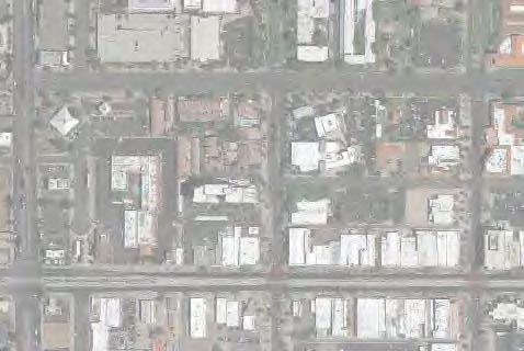
1. Project Site and Location
The project site is an existing museum on a parcel of approximately 2.3 acres in Mesa, Arizona. The museum is located at the northeast corner of the intersection of N. Robson and W. Pepper Place in COM’s Downtown Redevelopment Area, as outlined in COM’s Engineering and Design Standards. The existing site is composed of the museum building, multiple courtyard areas within the facility gates, paved parking and sidewalks around the exterior, and exterior landscape areas.
2.
Required Retention
Per the COM’s Engineering and Design Standards, total required retention for the site was calculated using the equation, V=cAp/12, where V is the required retention volume in cubic feet (cf), c is the overall runoff coefficient for the site based on site land use type(s), A is the overall drainage area in square feet (sf), and p is the total rainfall for the design storm in inches (in).
As previously noted, there are multiple land use types throughout the existing facility that will contribute to the weighted runoff coefficient. In accordance with Table 8.1 of the Engineering Design Standards for the 100-year frequency, 2-hour duration storm event , coefficients of 0.31, 0.50, and 0.95 were assumed for turf landscaping, desert landscaping, and pavement, rooftops, and concrete surfaces respectively. Using these values, a weighted coefficient for the project site was determined using the equation c=ΣA *c /A. Areas for each of the land uses were determined based on as-built drawings and supported by site observation. Results of the weighted runoff coefficient calculation can be seen in Table 1
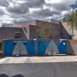
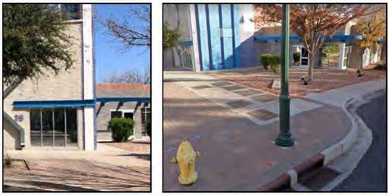
3. Existing Retention Provided
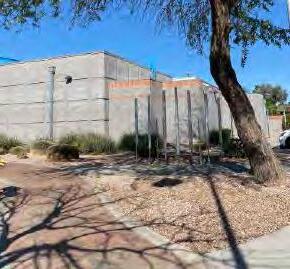
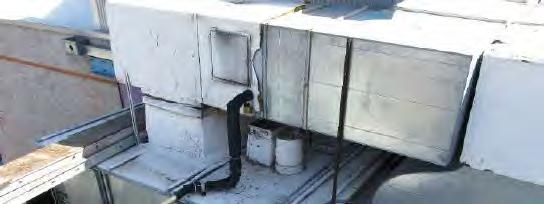
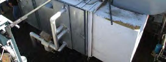
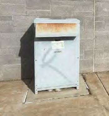
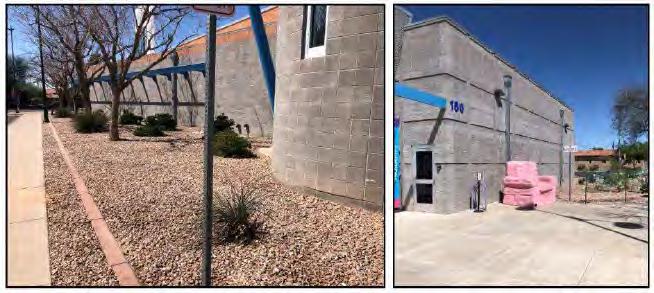
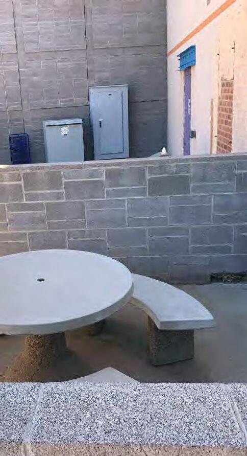
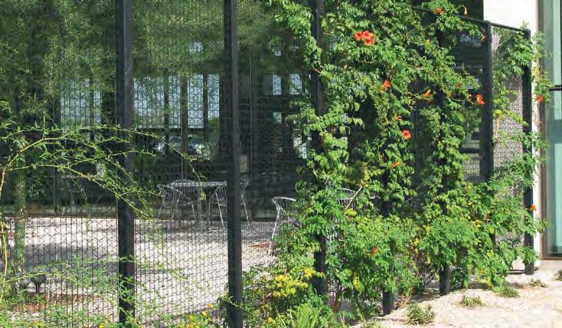
Based on onsite observation and a review of grading and drainage as-builts from 1996 and 2005, the sit e was determined to have 3 separate retention areas. Two of the existing retention areas are within the courtyard north of the main exhibit area on the west side of the museum. One of these retention areas is a large turf area that is depressed below all adjacent hardscape (Figure 1). Based on original as-builts, this retention area has a maximum depth of 1 foot and a storage capacity of approximately 3,400 cf. The other retention area within this courtyard is along the inside of the west site wall. This area is a depressed desert landscape area adjacent to hardscape and contains multiple utility features as well (Figure 2 ). This retention area also has a maximum depth of 1 foot, and it has a storage capacity of approximately 644 cf. The total storage capacity of the existing retention areas within the courtyard is approximately 4,044 cf.
As noted previously, the project site is within COM’s Downtown Redevelopment Area. According to the Engineering and Design Standards, a depth of 2.2 inches is assumed for retention calculations within COM, but only 2/3 of the standard rainfall depth is to be used in required retention calculations for properties within the Downtown Redevelopment Area. As such, a rainfall depth of 1.47 inches is to be used for the project site.
Using the weighted runoff coefficient, the total area of the lot, and the specified rainfall depth, the required volume for the existing condition was calculated to be 10,109 cf. This calculation can be seen in Table 2
Table 1 - Weighted Runoff Coefficient
Figure 1 - Existing Courtyard Turf Retention Area
VII. ENGINEERING NARRATIVES
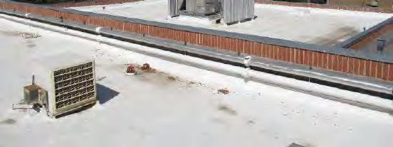
The third existing retention area noted on the site is within a large landscape area at the northwest corner of the site (Figure 3 ). This is the largest of the existing retention areas, as it provides 9,874 cf of storage at a maximum depth of 2 feet. This area is adjacent to the north side of the existing museum and the public sidewalk along the south side of W 1st Street and the east side of N Robson.
The total retention provided in the three areas noted is 13,918 cf, which is sufficient to store the required volume of 10,109 cf. In the existing condition, the site has an excess storage capacity of 3,809 cf, as can be seen in Table 3.
4.
Existing Site Grading and Drainage
Runoff from the existing site flows to the aforementioned retention areas via roof drain piping and surface flow. Based on site observations, all the roof drains around the facility appear to discharge above grade at the exterior of the existing buildings. According to the as-builts, and supported by site observations , the exterior areas on the south and west sides of the existing building are graded to convey runoff into W Pepper Place and N Robson, where it can be captured by the existing COM storm drain system. All other exterior areas – within the courtyards, parking lot, and along the north side of the site – are graded to convey runoff into the existing onsite retention basins described in the previous section. Runoff that overtops the existing retention basins within the courtyard flows out of the courtyard to the west and to the northeast. Runoff that flows west out of the courtyard flows into N Robson, where it can be captured by the existing COM storm drain system, and runoff that flows out to the northeast flows into the existing retention basin at the north side of the site.
B. Proposed Conditions
Several of the proposed improvements to the museum will impact the civil characteristics of the site. Specifically, improvements may increase the amount of required retention onsite, decrease the amount of retention provided onsite, and/or necessitate relocations of utilities and equipment. The areas of improvement that may impact the site civil design are the proposed Texture Trails and adjacent courtyard area (east), the Atrium courtyard area (northwest), and the Entry at the south side of the building. These areas can be seen in Figure 4. Proposed improvements for each of the areas have been broken out into base scope items, which are currently included in the project, and phased scope items, which are not currently included but may be added by COM based on project budget.
Figure 2 - Existing Courtyard Landscape Retention Area
Figure 3 - North Landscape Retention Area
Figure 4 - Proposed Improvements
VII. ENGINEERING NARRATIVES
Part of the phased scope throughout the site includes potential improvements to address ADA accessibility concerns of the existing facility. The recommended improvements are based on a report prepared for COM in November of 2019 by Sally Swanson Architects. There are portions of this phased scope within each of the identified improvement areas.
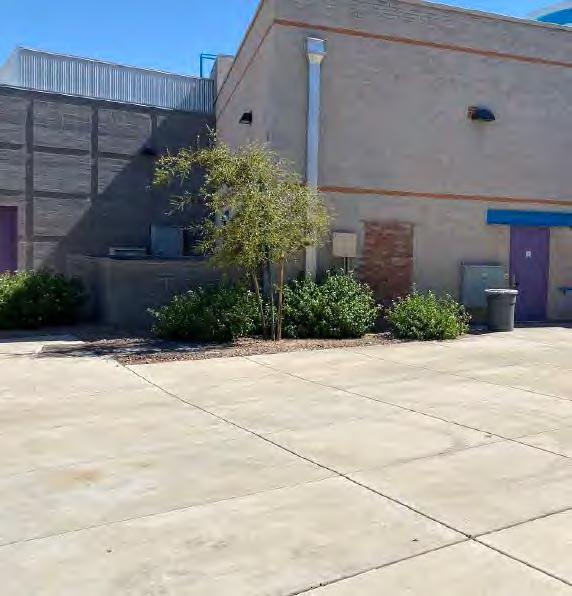
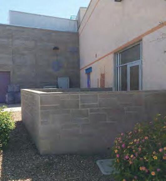
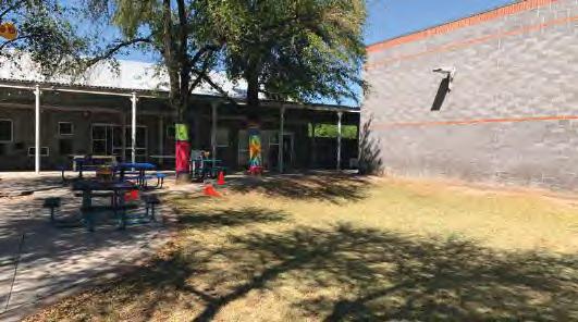
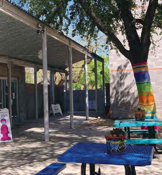
1. Texture Trails/East Courtyard
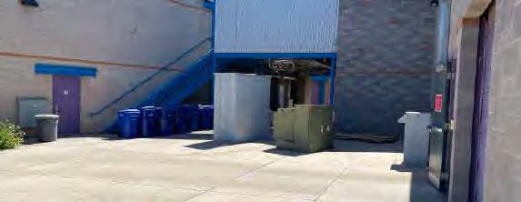
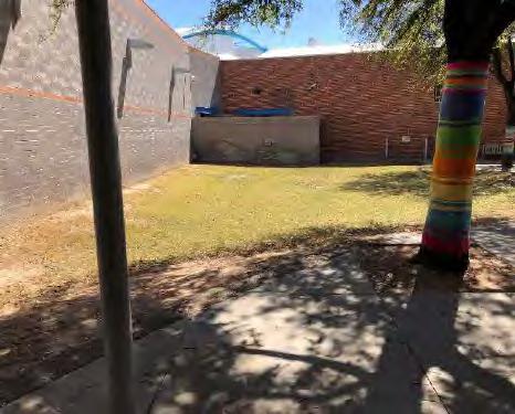
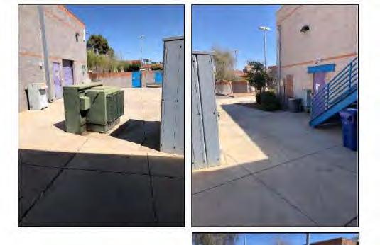
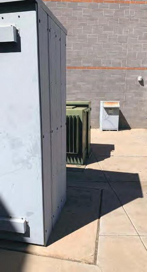
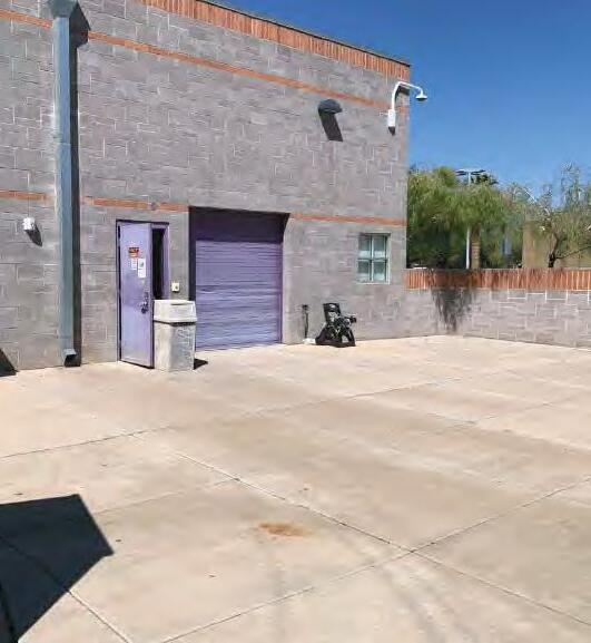
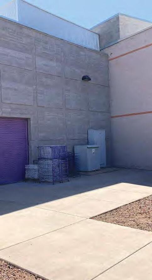
The proposed Texture Trails, part of the base scope, is intended to provide an outdoor exhibit with interactive tactile components. The adjacent courtyard space, part of the phased scope, will include an outdoor garden and social area for staff. The exist ing condition of both of these areas is generally characterized by paved surfaces with some small desert landscaped areas. Existing surface conditions can be seen in Figure 5
Due to the existing surface condition of this area being generally impervious, it is anticipated that the amount of required retention will not increase as a result of the proposed improvements. Any replacement of the desert landscape areas should be balanced by the proposed garden spaces in this area, so the weighted runoff coefficient for the overall area should not increase as part of this project.
Because there is no retention provided in this area currently, improvements to the area would not decrease the overall retention volume provided onsite. Retention for this area is provided in the existing northwest courtyard and in the existing landscape area north of the building along 1st Street. The proposed landscape improvements to this area include the addition of a raised curb planter between the Texture Trails space and the staff courtyard. While this will function as a stormwater capture and reuse entity, the amount of retention provided will not be sufficient for the overall area. The overall grading concept for the area should be maintained in the proposed condition to ensure that excess runoff from the area and the adjacent roof drains continues to flow to the existing retention areas.
As can be seen in Figure 5, there are multiple pieces of utility equipment on this portion of the site. Equipment in this area includes electrical transformers and cabinets, a light pole, and an underground utility vault. Pending the final layout of the improvements to this area, some or all of this equipment may need to be relocated in order to provide the intended exhibit and gathering space.
a. ADA Accessibility
Per the aforementioned report from November 2019, there are multiple ADA compliance concerns within the existing interior courtyard. At one of the existing doors to the courtyard, slopes outside the doorway exceed the maximum 2%, with slopes as high as 3.6%. The proposed solution is to modify the surface slope at the door.
At one of the other doorways, the required clearance is not provided on all sides of the doorway, as t here is an electrical panel within one foot of the door opening. See report for recommended building/electrical modifications.
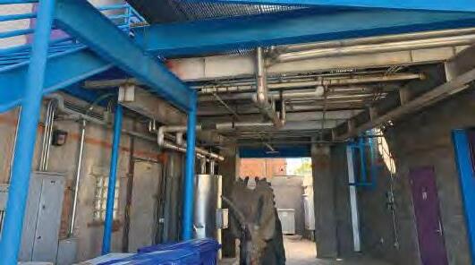
One of the noted non-compliant features within this courtyard is the existing set of stairs at the mechanical space. The report noted concerns with the stair risers, handrail, tread surface, and vertical clearance. See report for recommended architectural modifications.
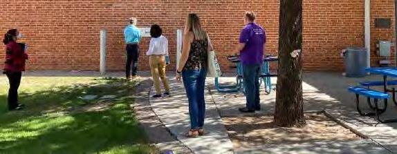
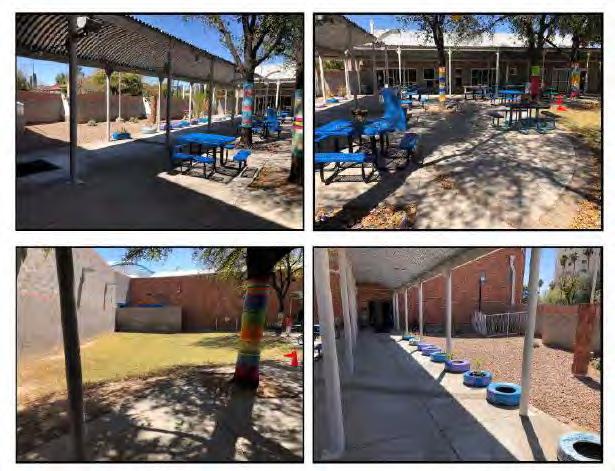
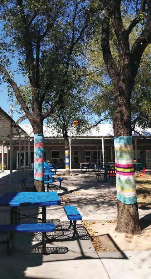
2. Atrium (Northwest Courtyard)
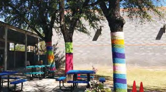
The proposed Atrium is intended to provide an outdo or gathering space, with a stage, seating, and patio access to the proposed cafe. The existing condition of this area includes a large turf area that functions as a retention basin, a smaller desert landscape area that also provides some retention volume, and paved areas providing seating and access between buildings and the parking lot. Existing surface conditions can be seen in Figure 6.
Dibble
2021
Figure 5 - East Courtyard Existing Condition
Dibble
2021
VII. ENGINEERING NARRATIVES
Proposed base scope improvements to the area include additional patio space adjacent to the proposed cafe and some patio seating space within the existing turf area. Based on converting these existing portions of landscape area to impervious surface, it is anticipated that the amount of required retention will increase as a result of improvements in this area. There are no additional landscape areas proposed to balance out the removal of landscaping, so the weighted runoff coefficient for the overall area will likely increase as part of this project. Proposed phased scope improvements include options to replace/modify the existing arcade canopy through the atrium, and to extend the limits of improvements west of the courtyard into the hardscape within the right-of-way. These improvements are not anticipated to have any impact on the runoff coefficient, as they would not change the surface condition of the existing area.
The addition of patio seating areas north of the cafe and within the existing turf area will reduce the amount of retention provided in both of these areas currently. The extent of the retention volume removed will depend on the final site plan layout for this area. As noted in Section I.A.3 , the existing site condition provides an excess storage volume of 3,809 cubic feet. If the additional required retention and reduced provided retention combine for more than the current excess storage volume, additional retention will need to be provided.
It is unlikely that additional surface retention will be an option due to the proposed improvements to the outdoor areas, so underground retention would likely be required. Any new retention that must be provided could be provided in underground infrastructure within the Atrium beneath any remaining turf and/or the proposed seating areas. This would allow for the overall grading concept to remain the same in this area, since the new retention will be provided in the same location as the existing retention that is lost. If the grading concept is maintained, the underground storage would require one or two surface inlets to capture runoff from this portion of the site.
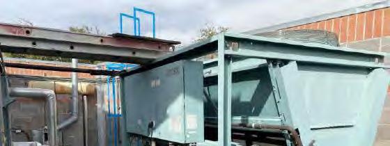
As can be seen in Figure 6, there are multiple pieces of utility equipment on this portion of the site, including an air conditioning unit and a backflow preventer for the facility’s fire service. To provide the proposed patio space at the cafe, the air conditioning unit will need to be relocated. Based on the current proposed site plan, the improvements are not anticipated to impact the existing backflow preventer.
a. ADA Accessibility
The existing Atrium space also contains several ADA non-compliant features throughout. As previously noted, addressing these concerns is part of the phased scope for this area.
There are slope concerns near each of the doors that exit out to public spaces. At the northeast door that exits to the north end of the site and toward the parking lot, cross slopes as high as 3.3% were observed, which is steeper than the maximum 2%. Surfaces slopes should be modified to a compliant design.
At the west door that exits to the sidewalk along North Robson, the ramp from the Atrium down to the door contains slopes in excess of 7% and no landing is provided on either side of the door. Because handrails are not currently provided, the maximum slope in the direction of travel should not exceed 5% in existing condition. If handrails were installed, slopes up to 8.33% would be acceptable per ADA requirements; however, landings would still be required on each side of the door. If these improvements are not feasible, signage should be provided within the Atrium and along North Robson, directing pedestrians to an accessible route.
The existing picnic tables within this space were also found to be out of compliance with ADA requirements. As part of the phased scope for this area, the tables should be replaced with ones that provide the appropriate minimum knee clearance.
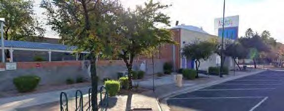
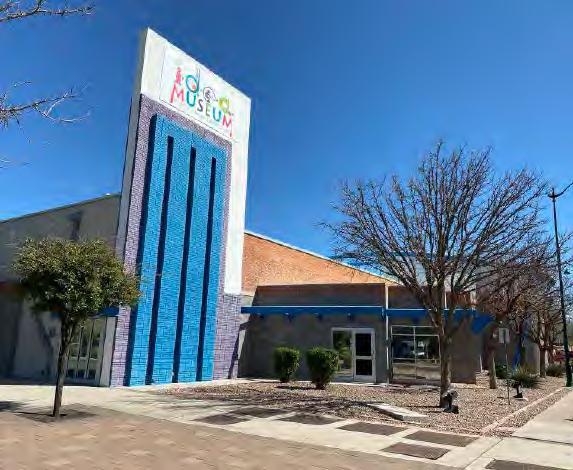
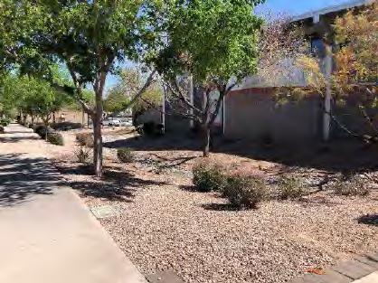
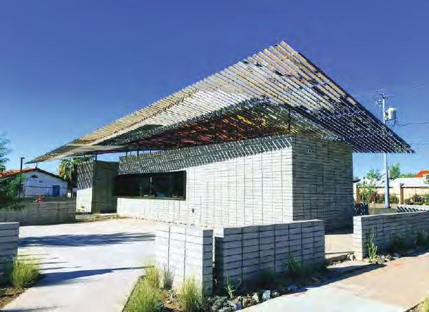
3. Entry
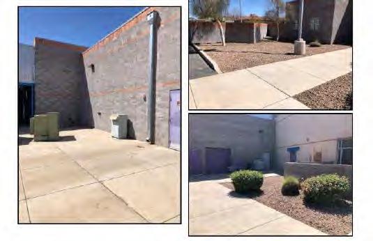
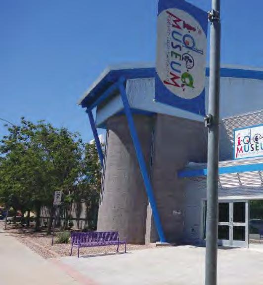
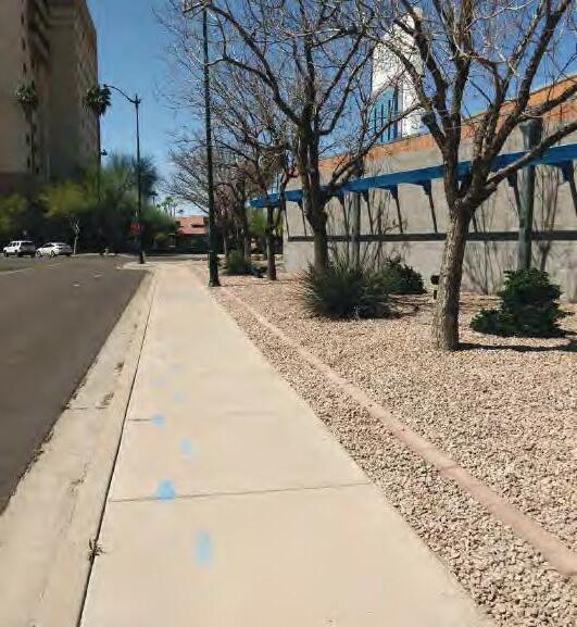
The proposed entry improvements are intended to provide a welcoming plaza area for the relocated main entrance and an interactive, shaded walkway connecting it to the parking lot. The existing condition of this area includes sidewalk to the existing access points and desert landscape areas between the building and the adjacent sidewalks along Pepper Place and Robson. Existing surface conditions can be seen in Figures 7 and 8
Dibble May 2021
7 Mesa i.d.e.a. renovation
Use Permit Narrative
Figure 6 - Northwest Courtyard Existing Condition
Dibble May 2021
Figure 7 - Southwest Entry Existing Condition
VII. ENGINEERING NARRATIVES
8 - South Exterior Existing Condition
Proposed base scope improvements to the area include additional paved sidewalk to provide a plaza outside the new main entry doors at the southwest corner of the building. Improvements along the south exterior may also include the addition of sidewalk to provide an interactive, shaded path to the entry. Phased scope improvements may include improvements to the north side of Pepper Place at the drop-off location and improvements to the plaza/landscape space at the southeast corner of the existing building, providing an improved experience from the parking lot to the new entrance. Based on converting some of the existing landscape area to impervious surface, it is anticipated that the amount of required retention for the site will increase as a result of improvements in this area. There are no additional landscape areas proposed to balance out the removal of landscaping, so the weighted runoff coefficient for the overall area will likely increase as part of this project.
Because there is no retention provided in this area currently, improvements to the area would not decrease the overall retention volume provided onsite. Runoff from this area and the roof drains that discharge to it surface flows into the adjacent Pepper Place and Robson streets, where it can be captured by the existing COM storm drain system. The overall grading concept for the area should be maintained in the proposed condition to ensure that runoff continues to flow offsite. Even though the runoff from this area flows offsite to the COM storm drain system, the additional required retention will need to be provided in the onsite retention areas in order to maintain the 2/3 capacity required for parcels in the Downtown Redevelopment Area, as discussed in Section I.A.2 . It may be possible to utilize some of these smaller landscape areas as shallow retention or bioswales to offset the difference in the increases runoff coefficient. Bioswales would ultimately outfall into Pepper Place to maintain the existing flow patterns. A full survey with the final design will provide additional information to determine how much can be retained in this south area.
As can be seen in Figure 7, there are multiple utility appurtenances on or near this portion of the site, due to its proximity to the right of way. Items in this area include a fire hydrant, street lighting, landscape lighting, and a series of underground utility vaults. It is anticipated that the public utility components would remain in existing condition; however, consideration should be given to the aesthetics of existing utility covers given that this area will become a focal point of the site.
a. ADA Accessibility
The only items noted within this area of the project are excessive cross slopes and thresholds at the existing doors. The requirements for the doorways should be accounted for in the design of the base improvements for this area. For doors not intended for public access, the requirements are not applicable, but the access point should be marked as such.
4. Additional Phased Scope Areas
a. ADA Accessibility
Some of the areas noted to be out of compliance with ADA requirements are outside the limits of the base scope of this project. These areas include the north end of the site adjacent to the existing retention basin and the existing parking lot at the east side of the site.
The existing path along the north side of the building, from the parking lot to the Atrium, contains cross slopes up to 2.8%, exceeding the maximum 2%. There is also a walkway connecting this north sidewalk of the museum to the sidewalk along the south side of 1st Street, which contains longitudinal slopes up to nearly 14%, which exceeds the maximum of 5%. Per the report, this path should be marked with signage that directs pedestrians to the ADA accessible route.
Multiple concerns were noted along the access path from the parking lot to the museum entrance, including excessive cross slopes, excessive longitudinal slopes, excessive dislocation of existing concrete causing abrupt level changes greater than ½ inch, and absence of truncated domes for detectable warnings at curb ramps where pedestrians enter vehicular areas.
Several items within the parking lot were also noted to be out of compliance with ADA requirements. Cracking in the asphalt pavement has created an irregular surface within the ADA parking spaces. One of the van accessible spaces at the ADA parking was noted to be out of compliance due to the adjacent access aisle. Lastly, per standards, the ADA parking signage should be modified to not include the word “handicapped.”
C. Summary
Based on as-built review and onsite assessment, it has been determined that the existing facility has sufficient retention storage provided to meet the required retention volume. The existing required retention has been calculated based on overall land use for the site, and the provided retention has been determined using civil as-built drawings.
The proposed improvements to the site will necessitate an analysis of the future drainage and retention characteristics of the site. The amount of retention required will likely increase slightly as a result of these improvements, and the amount of surface retention provided will likely decrease. As such, either a limited amount of underground retention may be needed to fulfill the retention requirements or some minor surface retention areas could be utilized to offset the difference. The amount of additional retention required will depend on the extent of the improvements to the existing turf area as this is the largest area of existing retention that could be impacted. It is also possible given the excess existing retention amount, that the proposed improvements would not increase the amount required enough to necessitate additional retention. Final concepts and a topo survey will be required to confirm this. Per the current concepts, it appears the existing amount and the amount required would be close to being balanced.
Site grading concepts are anticipated to remain similar to existing conditions throughout the site. However, surface utility features will need to be relocated in some of the improved areas to accommodate the proposed site layout. Features that may need to be relocated include electrical equipment and a light pole in the Texture Trails/staff courtyard area and an air conditioning unit within the Atrium adjacent to the proposed cafe.
All proposed improvements should be designed in consideration of current ADA accessibility requirements. Additional non-compliant areas throughout the site have been identified in a November 2019 report prepared for the City. If these areas fall within the final scope of the project, any ADA compliance issues should be resolved by the proposed improvements.
Figure
I.D.E.A .MUSEUM 15% CHECK-IN 05.31.2021
VII. LANDSCAPE NARRATIVE
PHASE ONE:
i.d.e.a. Museum Project
Scope
PHASE ONE CITY BOND:
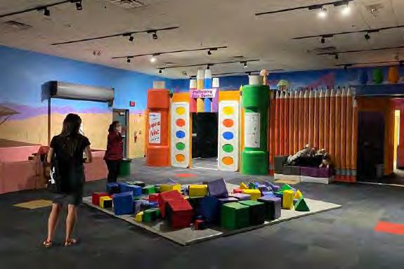
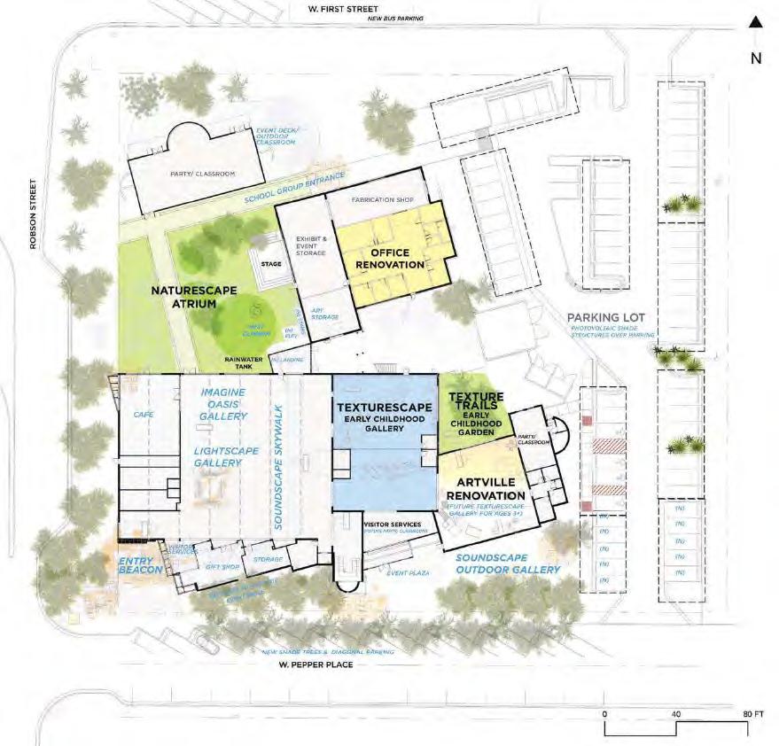
New Early Childhood Gallery: Architectural renovations will convert the ground floor administration to a new 4,095 sq. ft. gallery space called Texturescape. New exhibits will focus on highly tactile experiences and environments integrating gross and fine motor skill development, with hands on exploration of materials for ages birth-3 years.
New Early Childhood Garden: The new Texture Trails Early Childhood Garden invites visitors to refresh and ground themselves in art inspired by nature, outdoor exploration, full body experiences, and imaginative play for ages birth-3 years.
New Daylight at Existing Artville Gallery: Architectural renovations in the existing Artville Gallery will open up the space to daylight and garden views as well as increase comfort and energy efficiency with updated mechanical and electrical systems.
New Exhibits and Landscape Improvements at The Atrium: Nature play is integral to children’s social, psychological, academic and physical health. Activating the 9,500 sq. ft. Atrium with new exhibits and landscape improvements will provide opportunities for nature discovery and open ended play. The Museum will offer high quality event rental space and increase earning potential with a new performance stage and event seating and dining for 150 people.
Staff Office Relocation and Renovations: Relocating the Museum’s administrative offices from the first floor to the renovated second floor frees up 4,095 sq. ft. of prime gallery space. Design, development and education staff are relocated to the exhibit fabrication building, improving efficient work flows and collaboration.
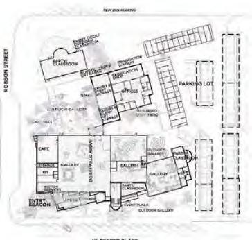
i.d.e.a. MUSEUM PROPOSED MASTER SITE PLAN SUBSEQUENT PHASES:
VII. LANDSCAPE NARRATIVE
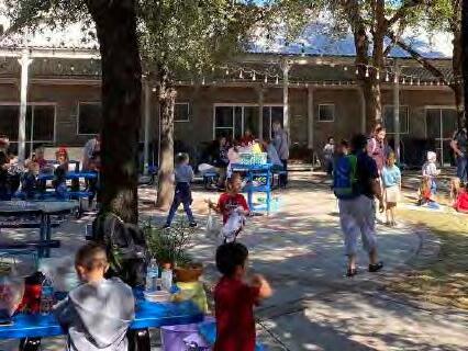
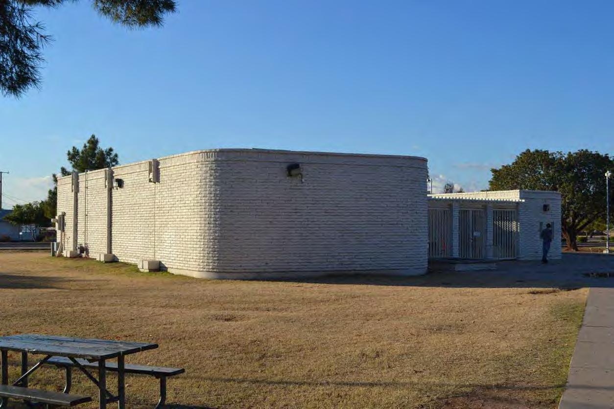
EXISTING CONDITIONS: SITE OVERVIEW
PEPPER PLACE
VII. LANDSCAPE NARRATIVE
DESIGN NARRATIVE: LANDSCAPE ARCHITECTURE OVERVIEW
Narrative:
The first phase museum Landscape Architecture improvements advanced in the 15% deliverable will primarily be in the outdoor space described as the Texture Trails. However, all the exterior spaces identified in this package need to be considered for a holistic approach to the user experiences and the ethos the museum promotes into the future. Immersive and thought provoking environments are a key component to the learning process and to engaging and creative activities. We aspire to create micro-climates, capture water, and provide shade in a way that heightens enjoyment, but also educates. We intend to make access, views, and connectivity be easy and user-friendly, but also interactive and experiential. We will look to use plants and materials that are tactile, diverse, and durable, while still creating a positive mindset for learning and imagination.
VII. LANDSCAPE NARRATIVE
DESIGN NARRATIVE: EMPLOYEE COURTYARD
Narrative:
The existing utilities and exposed nature of the space are the biggest challenges to address in this area. The cost of relocating the utilities may be prohibitive and adequate alternative locations with required access are limited. However, the existing structures do offer opportunities as well. The site conditions make the existing breezeway an attractive option for upgrading as a breakout space. The area may allow for seating and the structure could support extended shade.
Design Goals
• Provide Shaded Break Space
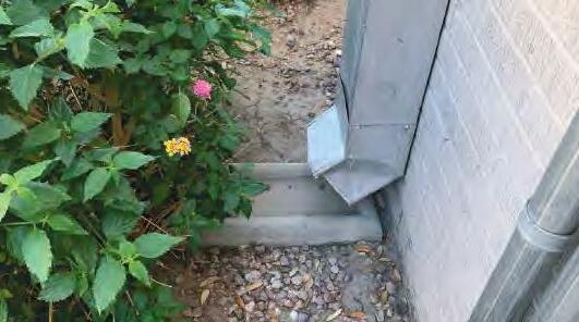
• Maintain and Improve Stormwater Collection from Roof Downspouts
• Maintain Access to Utilities
• Maintain Loading and Unloading Space
• Efficiently Address Utility Boxes/Cabinets
• Utilize and Transform Exiting Structures to Provide Needed Outdoor Space for Employees
• Improve Visual Delineation of Vehicular Access
VII. LANDSCAPE NARRATIVE
VII. LANDSCAPE NARRATIVE
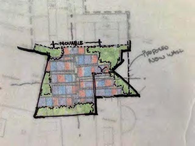
DESIGN NARRATIVE: TEXTURE TRAILS
The primary program of the texture trail space is to provide an immersive and interactive breakout space for the ‘Artville’ exhibit areas and classroom. To accomplish this several existing features in the space will need to be removed, relocated, or renovated. This includes the existing block wall and utilities along the future glass curtain walls.
To separate the space between the texture trails area and the employee courtyard and utility space, we propose an LID stormwater capture technique. This will channel the existing downspout into a raised curb planter. The planter will contain a vegetated barrier with controlled opening between the spaces.
Existing irrigation controllers and infrastructure will be made use of to irrigate new planting. Low voltage landscape lighting with 7 fixtures will add flexibility to the use of the space into evening hours. The low voltage transformer location will need to be coordinated moving forward.
Narrative: Design Goals
• Create Micro-Climates for Year-Round Outdoor Space
• Capture Water to Enhance Landscape
• Filter Polluted Storm Water Run-off
• Create an Immersive Environment that Heightens the Senses
• Provide Pleasant Viewing Experience from the Interior
• Safe Separation from Employee Area and Utilities
• Seasonal Transformations
• A Tactile and Visually Textured Experience
• Imaginative and Interactive
• Functional Small Group Breakout Space
VII. LANDSCAPE NARRATIVE
4: CONCEPTUAL DIRECTION
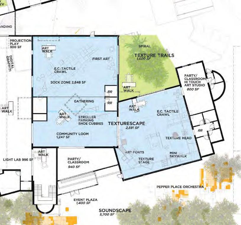
TEXTURE TRAILS: GYROSCOPE MASTER PLAN
ZONE: TEXTURESCAPE
Highly tactile experiences and environment integrating gross motor with fine motor hands-on exploration of materials. ‘Textile’, ‘texture’, and ‘text’ come from the same Latin root, meaning “to weave”. This zone combines experiences for children three years old and up, along with their caregivers, with a protected zone for the very young children birth to three. This strategy allows families to stay together with children of multiple ages.
The zone features a ‘Mini’ Skywalk, an art studio space, as well as a nursing area, access to bathrooms, and a new outdoor Early Childhood Texture Trails.
EXPERIENCE PLAN 1”=20’-0”
KEY EXPERIENCES FOR AGES 3+
• Art Walk
• Community Loom
• Art Forts
• Texture Head
• Texture Stage
• Mini Skywalk
• Make “Hi Touch” Art
KEY EXPERIENCES FOR EARLY CHILDHOOD AGES BIRTH-3 (E.C.)
• Art Walk
• Tactile Crawl (EC)
• First Art (EC)
• Gathering (EC)
• Texture Trails (EC)
• Spiral (EC)
• Snack/ Nursing Area (EC)
VII. LANDSCAPE NARRATIVE
TEXTURE TRAILS: OPTION
VII. LANDSCAPE NARRATIVE
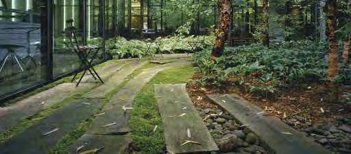
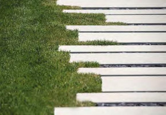
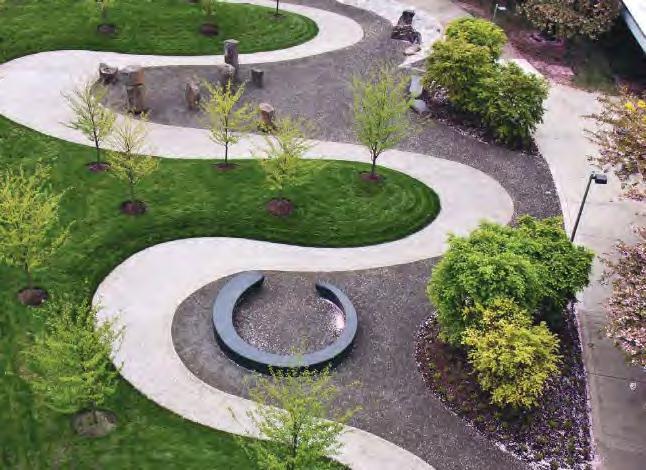
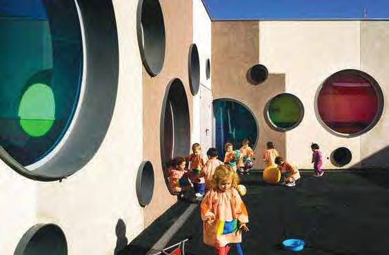
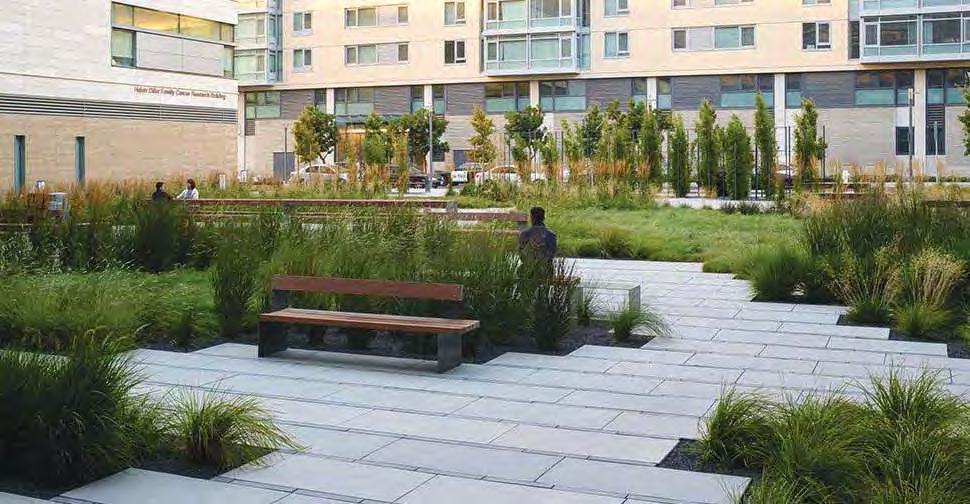
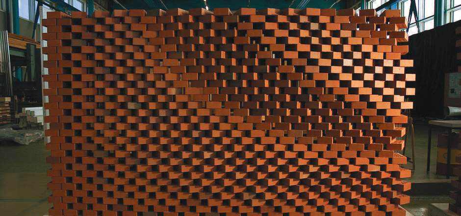
CONCEPT IMAGERY: TEXTURE TRAILS
VII. LANDSCAPE NARRATIVE
DESIGN NARRATIVE: ENTRY & STREETSCAPE
Narrative:
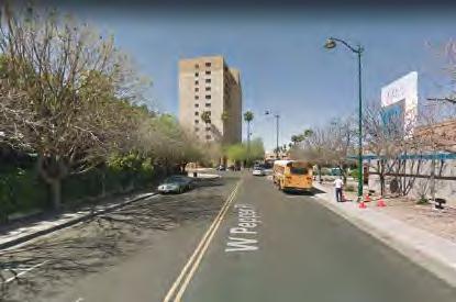
In future phases of the museum changes to the entry experience will shift the flow of people from the existing parking areas. The longer walk to the new entry, and the blank unshaded condition of the existing walkway, will need to be improved to ensure safe, shaded and engaging movement.
Design Goals
• Improve Physical Connectivity
• Provide Visual Cues and Clarity of Movement
• Expanded Interactive Features and Shaded Walkway Segments to Connect to New Entry
• Provide Buffer from Street and Parking for Safer Pedestrian Movements
• Emote the Museum’s Character and Mission with the Arrival and Entry Experience
VII. LANDSCAPE NARRATIVE
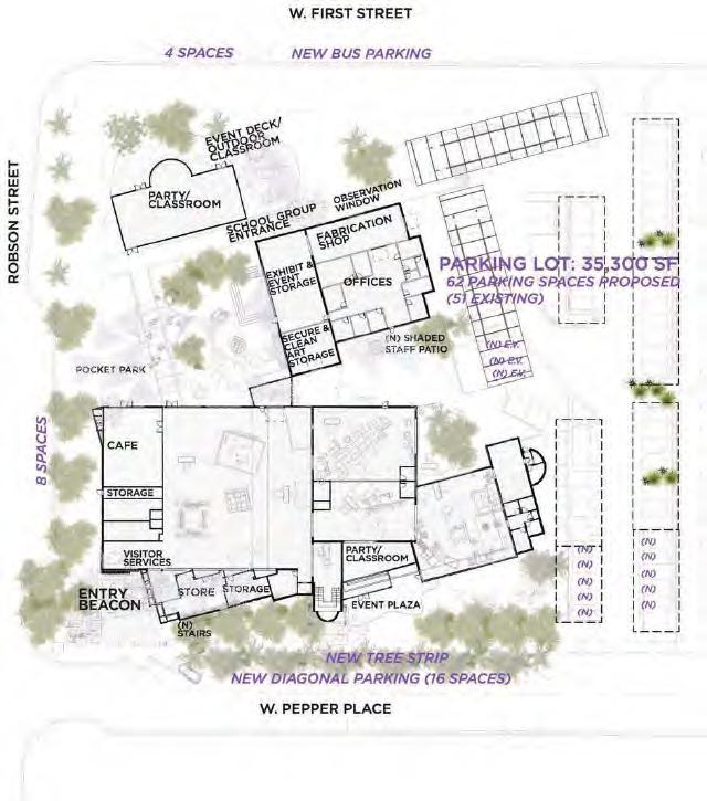
3: SITE & BUILDING
Existing parking lot (across street) = 77 spaces
Relocate bus parking adjacent to new school group entrance
New photo-voltaic shade structures
Provide new landscape island per zoning ordinance
Truck loading zone
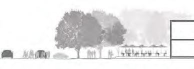
PEPPER PLACE EXISTING SECTION LOOKING WEST
Provide new landscape island per zoning ordinance
Straighten driveway to gain parking spaces
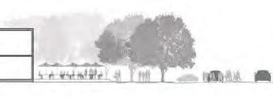
Put Pepper Place on a Road diet to gain diagonal parking and street trees.
PROPOSED ROAD DIET-PEPPER PLACE SECTION LOOKING WEST
VII. LANDSCAPE NARRATIVE
ENTRY & STREETSCAPE: OPTION
VII. LANDSCAPE NARRATIVE
CONCEPT IMAGERY: STREETSCAPE & ENTRY
VII. LANDSCAPE NARRATIVE
DESIGN NARRATIVE: NATURESCAPE ATRIUM
The Naturescape Atrium space is currently being addressed by internal fund raising efforts to implement various small scale improvements. In future phases of the museum upgrades this space may have additional enhancements and amenities added. The ground plane could be enhanced by leveling out uneven areas; offering more visual clarity and adding tactile cues. The enclosed space has the potential to be transformed by addressing the vertical surfaces and structures with art, color and lighting. The key landscape priority will be protecting the trees, and the grading and condition of the turf area will need to be modified with the addition of the stage.
Similar to other areas of the site, existing irrigation controllers and infrastructure will be made use of. Low voltage landscape lighting (7 fixtures) are proposed near the new cafe patio to extend its hours of operation. The low voltage transformer location will need to be coordinated moving forward.
Narrative: Design Goals
• Improve Group Entry Experience
• Expand Performance and Gathering Space Opportunities
• Enhance the Visual Impact of the Structures and Walls Surrounding the Space
• Maintain Tree Health and Their Shade Canopies
• Provide Environmental Comfort with Shade
• Improve Seating, Dining Spaces and Furnishings
• Address Grading and Drainage Improvements as Needed
VII. LANDSCAPE NARRATIVE
NATURESCAPE ATRIUM: COM INTERIM PLAN
EXIT TO ROBSON
MUSICAL FLOWERS ALONG WALKWAY MUSICAL GARDEN
EXISTING BACKFLOW PAINTED CLASSROOM BUILDING
CHALKBOARDWALL(INBETWEENWINDOWS)
TREES DINOSAUR NODE ON STABILIZED DECOMPOSED GRANITE
BUILDING
FEATURE POT
EXISTING POSTS PAINT TO MATCH IDEA LOGO SCHEME
WALKWAY FAIRY GARDEN
LINED PATH
PANELS AFFIXED TO FENCE
SHADE TREES RAINWATER HARVESTING DEMONSTRATION GARDEN TIRE PLANTERS ALONG PATH EDGES IN LANDSCAPE
YARN WRAPS AROUND TREES POTS AND LANDSCAPE IN TREE WELLS
VII. LANDSCAPE NARRATIVE
NATURSCAPE ATRIUM: OPTION
VII. LANDSCAPE NARRATIVE
CONCEPT IMAGERY: ARCADE
Dig Studio
City of Mesa
VII. LANDSCAPE NARRATIVE
Project Vision & Goals
The i.d.e.a. Museum Renovation Project will repurpose existing spaces within the current museum [a former Bashas grocery store] located at 150 W. Pepper Place, Mesa, AZ for new galleries, interactive public spaces, offices, and a new entrance zone. The improvements will be based Gyroscope’s 2018 Master Plan and informed by EMC2’s 2019 Feasibility Report. Per City of Mesa’s Scope Diagram [Attached] and priority spaces.
Guiding principles of the project remain as improving visitor experience, increase revenue, administrative reorganization, biophilia and activation of outdoor spaces.
Design team to take a holistic view of overlapping existing conditions in conjunction with Feasibility and Masterplan to create a detailed layout and systems plan at 15% SD level. The drawings will be used to generate a cost estimate/budget impact which will inform further phasing, scope and schedule.
Schedule
Start of construction of the first phase is scheduled for Fall of 2022. Initial design effort scheduled to be complete by Spring 2021. HSS will work with CoM, during schematic design to finalize the following milestones:
Purpose Initial scoping meeting to introduce project team and review project scope based on previous studies We reviewed existing conditions of the museum and presented preliminary phasing plan as understood by Holly Street Studio.
Scope Discussion
While the "short-term" project goal is to address the current problems at hand, the museum renovation will be guided by its long-term vision. Immediate needs include:
Administrative Reorganization (administrative and museum staff private and/or open offices, conference and team rooms):
- COVID-19 implications are changing the way we think about the workplace, from office quantities (some employees may either remain remote or may only be at the office part time) to the types of spaces (a mix of a dedicated [partitioned] and non-dedicated [shared open office] ). Other suggestions included a desire to have a central staff meeting place (reference Google collaboration hub) and "touch down" flex desks that can be converted to a staff desk when needed.
- A “best case scenario” includes organizing all staff in the Fab Shop building, possibility of small expansion of South side for more office space, depending on budget allocation. Could include indoor outdoor, shaded “staff patio”.
- The Fabrication Shop will not get any smaller, current footprint is ideal.
- Fab Shop building could be re-organized (partition Exhibit & Event Storage) for more flexible or increased storage capacity. This could also double as a “mini green room” for events and renters as needed.
- HSS requested the museum staff to provide future staff projections in order to plan for and provide adequate administrative space. Sunnee is meeting with museum staff on 1/13 to clarify employee capacity and general feedback for organization.
Upgrade Rental Spaces (Classrooms, Event Deck and Spaces, Cafe): - 2nd floor outdoor event space is not ideal. Outdoor event space could be on the street level.
- If staff could all move to the Fab Shop building, the 2 nd floor space could be designed as further flexible, rentable space.
- Classrooms are crucial for revenue generation, must be flexible enough for varying needs. Where possible, indoor/outdoor connections would increase value of space (Party/Classroom Atrium should spill out into outdoor space).
- Sunnee notes that a new apartment complex is going up directly across the street. This should be kept in mind for potential event programming (sound, visibility, etc).
- Café could be rentable space (as a sort of dining hall) and could open up to pocket park or atrium with visual / physical connections to the outdoor space. Upgraded cafe equipment and services may be a selling point to allure potential renters.
- Gift shop could be moved to a mostly “online” format to free up space, but likely would need some sort of flexible presence for exhibit specific sales. Sunee's also mentioned the current propsed Gift Shop SF is too big and could possibly be reduced in half
- Artville – visibility between spaces important for families of all ages (parents need to be able to monitor both toddlers + teens simultaneously).
Refresh and Expand Museum / Exhibit Space (Skybridge, Entry Lobby, Gift Shop)
- Diane suggesting of cleaning up new entry sequence with elements that tie into the rest of the streetscape rather than a massive landmark artwork. Goal of the “entry” is to draw attention to museum from street (competing with several established Mesa arts centers).
- Renovation of the Atrium space is a next level priority and can be taken out of scope as budget dictates
Refresh and Expand Back o House / Hidden Infrastructure (Storage, Janitor's, Elec, IT/Tel/Data, Structural, Mechanical, Plumping, and Electrical Systems):
- Off-site storage a possibility, depending on logistics of recurring exhibits, equipment, and available City of Mesa spaces. This could introduce further challenges in coordination, time and money for getting things in and out of storage. Jennifer suggests the possibility of a modular storage unit on site (parking lot or other).
- Storage needed for but not limited to: (100) chairs, (40) 6’ tables, currently on 4-5 carts. Other bulk furniture includes podium, sound equipment, bar materials, etc.
- Possibility of windowed views into MEP infrastructure to visitors as a sort of showcase / exhibit on how building’s work.
Create and Unify Indoor/Outdoor Space (Texture Trails and Gardens):
- Need to generate public interest with the Phase 1 work. Naturescape is a top priority due to COVID and visibility to the public.
- Texture Trails needs to connect to Artville.
- A possibility to add a 2nd floor rooftop garden was suggested, if an event space cannot be planned.
Miscellaneous:
- Some existing walls from original Basha’s footprint are extremely thick (24”). Should verify conditions for any new openings and connections.
- All restrooms need to be updated. HSS to confirm toilet room counts per code analysis.
- Design team should focus on getting to a good “vanilla shell”, lending more flexibility to connected spaces, visibility and circulation.
- Sunnee's announced her retirement. Her last day at i.d.e.a. museum is January 21. Jeffory will act as the Museum Director interim.
•
• On-site meeting with Structural + MPE to understand existing building systems and share ideas of proposed conceptual layout.
• HSS to develop and present conceptual plan.
• A series of brain storming workshops with HSS and user group for feedback and finalizing conceptual plan.
Attachments
• Scoping Meeting Presentation Part 2
• Meeting Notes by Ken Perkins, 07 23 2020 Prepared By
13 January 2021
Mesa i.d.e.a. Museum Renovations | Preliminary Phasing Plan
Mesa
Museum Renovations | Preliminary Phasing Plan 13 January 2021
i.d.e.a.
more exhibits and more dedicated spaces for early childhood families, the Museum has embarked on a visionary Site Master Plan to meet these needs. Gyroscope, Inc., a national museum planning, architecture and exhibition design company was selected for this master planning effort.
Project At A Glance
SITE: 150 W. Pepper Place, Mesa, AZ
SITE AREA: 2.3 Acre Site
BUILDING AREA: 33,000 SF
EXISTING INDOOR EXHIBIT AREA: 10,472 SF
PROPOSED INDOOR EXHIBIT AREA: 15,989 SF (153% Increase)
EXISTING OUTDOOR EVENT AREA: 9,600 SF
PROPOSED OUTDOOR EXHIBIT AREA: 23,432 SF (244% Increase)
EXISTING VISITOR CAPACITY: 1,903 people
PROPOSED VISITOR CAPACITY: 3,165 people (166% Increase)
CONCEPTUAL FRAMEWORK: ARTOOZE
EXHIBITS TYPOLOGIES: Imagine, Design, Experience, Art
AUDIENCE: Families with Children ages Birth-13
SCHEDULE: Completed in Two Phases
1: EXECUTIVE SUMMARY
The Need and Opportunities
During meetings with sixty-four stakeholders, including the Mayor and other government officials, a key phrase stood out: “Make it better, not bigger.” Clearly the Museum needs more space to meet increased demand and to generate more diverse revenue streams. However, as this new master site plan demonstrates, it is possible to increase visitor capacity without expanding the physical footprint by reorganizing and developing underutilized spaces and improving overall visitor flow.
Better utilization of space opens up the opportunity to double the early childhood galleries, meeting the needs for families learning together. Using art as a portal, exhibit experiences, activities and programs, serve as inspiration and personal expression in STEM, history, culture, literacy and language arts. Collectively, the program will emphasize 21st Century skills such as creativity, collaboration, innovation, and critical thinking while providing direct experiences with art.
As an active partner in Mesa’s Early Learning Network, the Museum will significantly strengthen its combined impact through expanded programming.
The Niche and Learning Focus
Launched in 1978, the Museum has distinguished itself from other local and regional cultural institutions by introducing fine art experiences to young children. The Museum’s niche since its founding has been and will continue to be as a hands-on Art Museum for Children and Families.
Engaging with local artists through artist-in-residences, art installations, special events and shared community programming, the Museum will become a showcase for innovative ideas, as well as for children’s own creative expression.
“Our
Biophilia
VIII. APPENDIX MEETING MINUTES
i.d.e.a . MUSEUM PROJECT ITEMS BY PHASE
i.d.e.a
Project Scope & Phasing
. MUSEUM PROJECT ITEMS BY PHASE
ONE:
PHASE TWO:
3: SITE & BUILDING
Circulation Plans
IMPROVE SENSE OF ARRIVAL
The new entry is leveraged to raise visibility, to create a dramatic sense of arrival and connect visually to the downtown arts district. Once inside the Museum, reimagined spaces and experiences encourage families to stay together without sorting by child’s age. All new exhibits include early childhood experiences, fine art and hands-on art activities throughout.
IMPROVED FLOW
• Ticketing, gift shop and cafe are adjacent at entry allowing for efficient use of staff.
• Exhibit design and education staff are co-located in exhibit workshop building for better use of space and improved workflow.
• Executive, marketing, and development staff are relocated to the 2nd floor offices opening up space to double size of EC gallery.
• New separate entrance for school groups from parking lot through Atrium; school lunches on new Atrium classroom deck.
PUBLIC AMENITIES
A new cafe is located along Robson Street with indoor/outdoor seating as well as access to the Atrium for catered facility rentals. The gift shop is located along W. Pepper Street: local art, art supplies in addition to children’s merchandise could be for sale. Both the cafe and gift shop could open before and after Museum hours.
OTHER IMPROVEMENTS
• Birthday party/classroom/multi-purpose space with access to outdoor gallery, separate entry and street
• North deck event space and school lunch area
• E xpanded Boardroom
• Outdoor EC classroom
SECTION THRU SKYWALK LOOKING EAST
2. SECTION THRU EARLY CHILDHOOD
1. SECTION THRU GALLERIES LOOKING NORTH
VIII. APPENDIX MEETING MINUTES
Mesa i.d.e.a. Museum Renovations | EMC2 Feasibility Study Map
January 2021
Second Floor 10. Event Deck
New Entry 7. Main Exhibit Hall 8. Cafe
1. New Gallery (Artville) Expansion
VIII. APPENDIX MEETING MINUTES
13 January 2021
Mesa i.d.e.a. Museum Renovations | EMC2 Feasibility Study
VIII. APPENDIX MEETING MINUTES
13 January 2021
Mesa i.d.e.a. Museum Renovations | EMC2 Feasibility Study
VIII.
DRAFT
Mesa i.d.e.a. Museum Renovations EMC2 Feasibility Study
VIII. APPENDIX MEETING MINUTES
Mesa i.d.e.a. Museum Renovations | EMC2 Feasibility Study
January 2021
VIII. APPENDIX MEETING MINUTES
• Enlarge window openings
• Replace (2) 6-Ton Split Systems with 12.5 Ton Split System HVAC
• Add window openings at north wall
• Convert retention basin to outdoor learning space
• Add underground retention tanks & drywell
• Add structural support and concrete topping to existing deck
• Remove existing roof system
• Provide water proof deck coating
• Add structural steel stairs for second exit
• Add fabric shade canopy
13 January 2021
Mesa i.d.e.a. Museum Renovations EMC2 Feasibility Study
VIII. APPENDIX MEETING MINUTES
Mesa i.d.e.a. Museum Renovations | Preliminary Phasing Plan
January 2021
VIII. APPENDIX MEETING MINUTES
Mesa i.d.e.a. Museum Renovations | Preliminary Phasing Plan
January 2021
VIII. APPENDIX MEETING MINUTES
25 January 2021 Mesa i.d.e.a. Museum Renovations SMPE site walk Location 150 W. Pepper Place, Mesa, AZ 85201-7326
Project Vision & Goals
The i.d.e.a. Museum Renovation Project will repurpose existing spaces within the current museum [a former Bashas grocery store] located at 150 W. Pepper Place, Mesa, AZ. for new galleries, interactive public spaces, offices, and a new entrance zone. The improvements will be based Gyroscope’s 2018 Master Plan and informed by EMC2’s 2019 Feasibility Report. Per City of Mesa’s Scope Diagram [Attached] and priority spaces
Guiding principles of the project remain as improving visitor experience, increase revenue, administrative reorganization, biophilia and activation of outdoor spaces.
Design team to take a holistic view of overlapping existing conditions in conjunction with Feasibility and Masterplan to create a detailed layout and systems plan at 15% SD level. The drawings will be used to generate a cost estimate/budget impact which will inform further phasing, scope and schedule.
Schedule
Start of construction of the first phase is scheduled for Fall of 2022. Initial design effort scheduled to be complete by Spring 2021. HSS will work with CoM, during schematic design to finalize the following milestones:
Jennifer Donahue, Project Manager, main POC Brian Spoon
i.d.e.a. Museum (IDEA)
Jeffory Morris, Museum Curator
Holly Street Studio (HSS) Diane Jacobs, Principal-In-Charge Annette Park, Project Designer
Pangolin Structural (PS) Crystal Blanton, Principal
Energy Systems Design (ESD) Andy Nathal, Electrical Evan Veregge, Mechanical
Discussion
Purpose: Site walk to review existing Structural, Mechanical, Plumbing and Electrical and discuss projects goals related to each discipline.
Structural:
• The original Basha’s building may have had a 2nd floor admin space, right above the proposed Café between gridlines B/3-5. Further investigations are needed to determine feasibility of adding administrative offices to this area, if a second floor exists. CoM and IDEA will schedule a time to visit this area for feasibility and share findings with AE team.
• Due to inclement weather, roof observations were deferred to another day.
• Review of existing second floor for potential modifications to partitions and openings at west wall for visibility to galleries.
Mechanical:
• Project goal is to cleanup, clarify and consolidate the current mechanical systems.
• Existing chiller needs to be replaced with one that can tie into CoM’s system (located on Pepper Place).
• The main museum building and north classroom buildings are independently operated and can remain as is
MINUTES 25 January 2021
Mesa i.d.e.a. Museum Renovations SMPE site walk Location 150 W. Pepper Place, Mesa, AZ 85201-7326
Electrical:
• The main exhibit halls currently get power from overhead ceiling mounted receptables. BS and JM expressed an interest in a gridded floor mounted trenched solution, as it will provide the greatest flexibility and clarify overhead views.
• ESD to advise if current lighting loads are adequate for museum fit-out. ESD was involved in a 2018 museum lighting study to provide recommendations, but as new programs are added to project scope, further studies may be required.
• All existing lighting in project scope to be removed and upgraded with LED lighting.
• UV and Plasma lighting were discussed as a strategy for sanitizing spaces. IDEA expressed a dislike for UV lights due to maintenance and degenerative properties. UV lighting preferred and direction to proceed with.
Plumbing:
• Current facilities do not provide enough space and quantities for visitor loads. HSS to look into code required versus recommended quantities and advise on layouts, locations, and amounts.
• Existing in-slab plumbing lines (running north and south, adjacent to restroom and café area at gridline B) may conflict with CoM/IDEA desired floor trenched electrical lines.
Upcoming Meeting / Next Steps
1. All disciplines to review 2019 feasibility study against site observations
2. All disciplines to review existing/as-built drawings against site observations.
3. HSS distributed i.d.e.a. Museum as-builts to consultants.
4. JD and JM to schedule a meeting to investigate possible 2nd floor above café.
5. HSS to share initial conceptual plans with CoM and pass along to consultants post review.
6. Consultants to review site findings and concept designs for presentation of recommendations at upcoming team meeting, expected for end of week of February 1.
7. Design team workshop to review conceptual plans.
Attachments
• N/A
Prepared By
• Annette Park, Diane Jacobs HSS will rely on these notes as the approved record of matters discussed and conclusions reached during these meetings unless written notice to the contrary is received by HSS within seven calendar days of the issue date of these minutes.
VIII. APPENDIX MEETING MINUTES
Project Vision & Goals
The i.d.e.a. Museum Renovation Project will repurpose existing spaces within the current museum [a former Bashas grocery store] located at 150 W. Pepper Place, Mesa, AZ for new galleries, interactive public spaces, offices, and a new entrance zone. The improvements will be based Gyroscope’s 2018 Master Plan and informed by EMC2’s 2019 Feasibility Report. Per City of Mesa’s Scope Diagram [Attached] and priority spaces.
Guiding principles of the project remain as improving visitor experience, increase revenue, administrative reorganization, biophilia and activation of outdoor spaces.
Design team to take a holistic view of overlapping existing conditions in conjunction with Feasibility and Masterplan to create a detailed layout and systems plan at 15% SD level. The drawings will be used to generate a cost estimate/budget impact which will inform further phasing, scope and schedule.
Schedule
Start of construction of the first phase is scheduled for Fall of 2022. Initial design effort scheduled to be complete by Spring 2021. HSS will work with CoM, during schematic design to finalize the following milestones:
Holly Street Studio (HSS) Diane Jacobs, Principal-In-Charge Annette Park, Project Designer
Purpose Design presentation of Level 1 + 2 conceptual plan.
The attached conceptual diagrams reflect feedback and next steps toward plan development and should serve as a graphic (+comments) record of the meeting discussion as well as earlier comments provided by JD/IDEA on PDF - via email. HSS responses included in comment summary.
Revised conceptual plan was provided on 12 February 21 reflecting progress development of the project as a result of meeting and is attached for reference as well
Upcoming Meeting / Next Steps
1. JD to schedule meeting with CoM for internal review/approval of conceptual plan.
2. HSS to follow up with Gyroscope.
3. HSS to pass along conceptual plan to consultants (for feasibility of work) after approval.
4. HSS to develop conceptual plan and schedule another design meeting w/ CoM + IDEA.
5. Workshops to follow.
Attachments
• Meeting Comments per 11 Feb 2021
• CoM Review Comments per 10 Feb 2021
• Modified Concept Plans per 12 Feb 2021
Prepared By
• Annette Park Diane Jacobs HSS will rely on these notes as the approved record of matters discussed and conclusions reached during these meetings unless written notice to the contrary is received by HSS within seven calendar days of the issue date of these minutes.
The i.d.e.a. Museum Renovation Project will repurpose existing spaces within the current museum [a former Bashas grocery store] located at 150 W. Pepper Place, Mesa, AZ for new galleries, interactive public spaces, offices, and a new entrance zone. The improvements will be based Gyroscope’s 2018 Master Plan and informed by EMC2’s 2019 Feasibility Report. Per City of Mesa’s Scope Diagram [Attached] and priority spaces.
Guiding principles of the project remain as improving visitor experience, increase revenue, administrative reorganization, biophilia and activation of outdoor spaces.
Design team to take a holistic view of overlapping existing conditions in conjunction with Feasibility and Masterplan to create a detailed layout and systems plan at 15% SD level. The drawings will be used to generate a cost estimate/budget impact which will inform further phasing, scope and schedule.
Schedule
Start of construction of the first phase is scheduled for Fall of 2022. Initial design effort scheduled to be complete by Spring 2021. HSS will work with CoM, during schematic design to finalize the following milestones:
s HSS shared overall strategies based on extensive study of existing architectural, structural, mechanical, electrical and plumbing conditions as well as work sessions with consulting team - to accommodate Master Plan goals in both current and future phases.
Renovation Concept - tread lightly on the existing structure, provide a flexible and open backdrop for a wide variety of exhibits + experiences, provide necessary infrastructure to support the art-inspired theme of the museum. Focus architectural renovation on revealing building structure, removing and / or organizing obstructive structural elements resolve pinch-points in plan resulting from clashing interior and exterior geometries so the program can thrive.
• Proximity to power, light, water, data, storage.
• Upgrading of systems for efficiency and sustainability.
• Expression of structure, converging geometries, textures, finishes
• Removal of barriers with addition of storage.
• Seamless connection to the outdoors for both front and back of building.
• Appropriate scale for all sizes and ages.
Mtg 5 - 06 May 2021
Updated Architectural Floor Plan
M I N U T E S Mesa i.d.e.a. Museum Renovations Location 5-7
Mtg 6 - 11 May 2021
Mtg 7 - 13 May 2021
Proposed Mechanical Strategies
Proposed Landscape Strategies Video Conference
• Accessibility for all levels of ability.
• Clarity of circulation, wayfinding via singular circulation spline/exhibit hall
• Creating a sequential, spacious and safe exterior/interior entry/transition experience.
• Increased revenue spaces – upstairs and outside
• Careful integration of new electrical rooms, conduit runs and mechanical diffusers at galleries.
• Consolidating staff, and providing new places for training and gathering.
• Landscape Architecture with non-prescriptive, open, flexible designs for variety of use.
1. Updated Architectural Floor Plan (Meeting 5)
2. Proposed Mechanical strategies (Meeting 6)
3. Proposed Landscape strategies (Meeting 7)
M
The updated conceptual plan was presented to show design evolutions since the last staff presentation on 2/11/2021 An overview of project goals, existing conditions to mechanical strategies were explained to clarify current floor plan layouts.
Feedback from i.d.e.a. /CoM staff
• Entry/Exhibit Hall –Proposed design to clarify building corner at entry and create new windows along south edge was favored. As the new entry relocates to southwest corner, i.d.e.a. staff favorably embraced the opening of views in and out of the museum to activate the experience for visitors and pedestrians CO referenced the “Endless Bridge/Guthrie Theater” in Minneapolis as an example of this condition where the museum could achieve a similar affect.
• Visitor experience –A desire for each area to be differentiated as individual exhibit zones is desired. Strong circulation spline will tie all together, help with wayfinding and allow for direct views from one space to another.
• L Wall –Expressed positive interest in this this element as it functions to distinguish entry and exhibition space Suggestions for use include storage, locker, exhibit display, and greeting desk opportunities HSS wil engage with staff on designing L Wall together Design considerations were material transparency, modularity of wall configuration for flexibility, apertures in wall for visibility.
• Artville –Visibility between Artville 1 + 2 is important. Proposed storage room at two intersecting volumes creates too much of a visual barrier. HSS will look at lowering or removing storage room in order to create lines of sight from Artville 1 + 2. Proposed glazed roll-up doors were met with positive feedback allowing for wider openings for a stronger interior + exterior connection Roll up doors are part of the existing building visual vocabulary as well as the neighboring Mesa Arts Center.
• Storage –The staff does not yet have quantifiable input on storage requirements Proposed storage capacity felt okay but could not be confirmed. CO suggested i.d.e.a. staff create a review + quantify existing storage space (in cubic feet) and compare with proposed storage capacity. * s t a f f a c i o n i e m
• Proposed Mechanical Strategy –A diagrammatic overview of proposed strategies was presented. JD requested a dedicated meeting with Brian Spoon/CoM and MEP + design team to review. (See Meeting 6 below)
An overview of Proposed Mechanical Plan was presented, with detailed explanations to strategies. Additional meeting notes + feedback is recorded in the attached “Mechanical Strategies Proposed Plan.pdf
High-level takeaways are:
• Existing CW unit at exterior mezzanine platform suggested to be replaced. ESD recommends installation of an interior plate + frame heat exchange chiller. Suggested location of the unit to be located at north side at existing Fab Lab Storage (at mezzanine level), as existing CoM chilled water main connects closely and distributes efficiently to museum
• Replacement of Rooftop units at Zones 3+4 originally slated for replacement, can be removed from current project scope and considered for future replacement and tie in to District chilled water systems at a later phase.
• Existing air handler unit that serves current Exhibit area can remain. Scope to demo finished ceiling and exposed wood truss girders + purlins will cause some level of redesign existing duct locations + routing and should be included as scope for pricing exercise.
• New and separate functions for offices + staff at Building 2 will require new individual rooftop units
Purpose of meeting was to review Proposed Landscape Strategies as a means to clarify programmatic expectations for outdoor areas – noting the role of hard and softscape interventions at this stage - as supplementary and flexible for future exhibit uses.
Landscape scope includes 4 areas:
• Texture Trails – Goal is to create a learning space immersed in nature as an outdoor exploratory lab. Discussions surrounding how landscape design revolved around the question of Landscape as a Backdrop or Landscape as nteractive Exhibit. With this in mind, 2 options were presented and both received favorably.
o Option 1 Radial ayout: a mix of planting, artificial turf, and pavers. Elements were part of a permanent solution, as elements not designed for moving or relocating
o Option 2 Homogenized/field layout allowing for flexibility addition of exhibits and rotating events. Graphic vocabulary to be comparable to a more open and linear arrangement of elements with staff’s input as the plan develops. This option was preferred by staff
Also, the current site wall geometries by east trash enclosure cause inefficient usable space By relocating the enclosure and/or simplifying layout with (1) trash, IDEA staff will have a more efficient layout for future exhibits and events. HSS to look at redesigning trash enclosure layout for final deliverables.
• Staff Courtyard – Proposed design will allow for a separation of spaces but can also work together with Texture Trails layout Elements should spill in and out of both areas, to create one holistic zone, with 2 distinct activity areas. This will allow for full use of the overall courtyard for special larger scale events as needed.
• Entry and streetscape along Pepper Place
o Extend interior museum footprint for additional program opportunities, via garage doors, small openings.
o Create meandering and non-directional flow
o Extend sidewalk to open up pedestrian traffic and plant vegetation for shade JD to research possibility of eliminating current on-street parking for additional sf for procession to entrance * s t a f f a c t o n t e m
o Explore design options at east side as future phased project.
• Atrium – Needs to serve 4 distinct purposes and areas: stage, café, museum learning/exhibits school bus drop off zone. Proposed design was approved with comments
o Must accommodate about 125 children combined for lunch, gathering, performance viewing.
o Space must be adaptable. Daytime museum functions should convertible to nighttime events + galas
o Create a safe and friendly path for school children coming in for tours.
Upcoming Meeting / Next Steps
• IDEA to quantify current storage space.
• HSS to quantify proposed storage capacity.
• ESD/HSS site visit to observe current electrical room. (occurred 05.13.21)
• JD to schedule CoM upper management meeting to present project scope.
Attachments
• Conceptual Design Progress for Staff per 06 May 2021
• Mechanical Strategy Presentation per 11 May 2021
• Landscape Presentation per 13 May 2021
Prepared By
• Annette Park + Diane Jacobs
HSS will rely on these notes as the approved record of matters discussed and conclusions reached during these meetings unless written notice to the contrary is received by HSS within seven calendar days of the issue date of these minutes.
i.d.e.a. Museum | Conceptual Design Progress
masterplan + feasibility study goals:
* create * discover * play * gather * engage * * open + organize + upgrade systems * create backdrop for all *
i.d.e.a. Museum | Conceptual Design Progress
architectural + engineering strategies
* Flexibility for changing exhibits and programs *
* Proximity to power, light, water, data, storage *
* Upgrading of systems for efficiency and sustainability *
* Expression of structure, geometries, textures, finishes *
* Connection to outdoors: front + back of building *
* Appropriate scale and Accessibility for all sizes and ages *
* Clarity of circulation, wayfinding: sense of whole to part *
i.d.e.a. Museum | Conceptual Design Progress
architectural + engineering strategies
* Resolving structural loads to create openness.
* Integration of new electrical mechanical components *
* Removal of layers of finishes to expose structure and textures *
* Increase visibility for families to stay ‘together’ while exploring all *
* Create a safe, secure, manageable entry zone with staff zones *
* Connect multiple activities along an open, singular circulation spline *
* Flexible * Adaptable * Free Flowing Spaces *
* Unify staff with new places for training and gathering *
VIII. APPENDIX MEETING MINUTES
i.d.e.a.
Museum | Conceptual Design Progress
existing building structure + recommended interventions
i.d.e.a. Museum | Conceptual Design Progress
proposed renovations - plans and views architecture + landscape
VIII. APPENDIX MEETING MINUTES
View at new entry looking east
VIII. APPENDIX MEETING MINUTES
View in front of elevator/stair looking west to new entry
View at exhibit looking south
05 06_Conceptual Design Progress for Staff
VIII. APPENDIX MEETING MINUTES
View at exhibit looking south west
Faye Gray Recreation Center
Faye Gray Recreation Center
project example that demonstrates flexibility, adaptability, visbility
The first phase museum Landscape Architecture improvements advanced in the 15% deliverable will primarily be in the outdoor space described as the Texture Trails. However, all the exterior spaces identified in this package need to be considered for a holistic approach to the user experiences and the ethos the museum promotes into the future.
Immersive and thought provoking environments are a key component to the learning process and to engaging and creative activities. We aspire to create micro-climates, capture water, and provide shade in a way that heightens enjoyment, but also educates. We intend to make access, views, and connectivity be easy and user-friendly, but also interactive and experiential. We will look to use plants and materials that are tactile, diverse, and durable, while still creating a positive mindset for learning and imagination.
VIII. APPENDIX MEETING MINUTES
DESIGN NARRATIVE: EMPLOYEE COURTYARD
Narrative:
The existing utilities and exposed nature of the space are the biggest challenges to address in this area. The cost of relocating the utilities may be prohibitive and adequate alternative locations with required access are limited. However, the existing structures do offer opportunities as well. The site conditions make the existing breezeway an attractive option for upgrading as a breakout space. The area may allow for seating and the structure could support extended shade.
Design Goals
• Provide Shaded Break Space
• Maintain and Improve Stormwater Collection from Roof Downspouts
• Maintain Access to Utilities
• Maintain Loading and Unloading Space
• Efficiently Address Utility Boxes/Cabinets
• Utilize and Transform Exiting Structures to Provide Needed Outdoor Space for Employees
• Improve Visual Delineation of Vehicular Access
DESIGN NARRATIVE: TEXTURE TRAILS
Narrative:
The primary program of the texture trail space is to provide an immersive and interactive breakout space for the ‘Artville’ exhibit areas and classroom. To accomplish this several existing features in the space will need to be removed, relocated, or renovated. This includes the existing block wall and utilities along the future glass curtain walls.
To separate the space between the texture trails area and the employee courtyard and utility space, we propose an LID stormwater capture technique. This will channel the existing downspout into a raised curb planter. The planter will contain a vegetated barrier with controlled opening between the spaces. Within the texture trails space further design options will be developed: One, a smaller break out patio leading to a “forest“ path, and another with a central patio space with denser and more diverse planting materials surrounding it.
Design Goals
• Create Micro-Climates for Year-Round Outdoor Space
• Capture Water to Enhance Landscape
• Filter Polluted Storm Water Run-off
• Create an Immersive Environment that Heightens the Senses
• Provide Pleasant Viewing Experience from the Interior
• Safe Separation from Employee Area and Utilities
• Seasonal Transformations
• A Tactile and Visually Textured Experience
• Imaginative and Interactive
• Functional Small Group Breakout Space
4: CONCEPTUAL DIRECTION
TEXTURE TRAILS: GYROSCOPE MASTER PLAN
ZONE: TEXTURESCAPE
Highly tactile experiences and environment integrating gross motor with fine motor hands-on exploration of materials. ‘Textile’, ‘texture’, and ‘text’ come from the same Latin root, meaning “to weave”. This zone combines experiences for children three years old and up, along with their caregivers, with a protected zone for the very young children birth to three. This strategy allows families to stay together with children of multiple ages.
The zone features a ‘Mini’ Skywalk, an art studio space, as well as a nursing area, access to bathrooms, and a new outdoor Early Childhood Texture Trails.
KEY EXPERIENCES FOR AGES 3+
• Art Walk
• Community Loom
• Art Forts
• Texture Head
• Texture Stage
• Mini Skywalk
• Make “Hi Touch” Art
KEY EXPERIENCES FOR EARLY CHILDHOOD AGES BIRTH-3 (E.C.)
• Art Walk
• Tactile Crawl (EC)
• First Art (EC)
• Gathering (EC)
• Texture Trails (EC)
• Spiral (EC)
• Snack/ Nursing Area (EC)
TEXTURE TRAILS: OPTION
2. Texture trail loop
3. Planting
4. Artificial turf
5. Tulip shade structure above
6. LID Infiltration channel
7. Saw cut existing concrete at employee courtyard
Texture Trails art installations throughout.
DESIGN NARRATIVE: ENTRY & STREETSCAPE
Narrative:
In future phases of the museum changes to the entry experience will shift the flow of people from the existing parking areas. The longer walk to the new entry, and the blank unshaded condition of the existing walkway, will need to be improved to ensure safe, shaded and engaging movement.
Design Goals
• Improve Physical Connectivity
• Provide Visual Cues and Clarity of Movement
• Expanded Interactive Features and Shaded Walkway Segments to Connect to New Entry
• Provide Buffer from Street and Parking for Safer Pedestrian Movements
• Emote the Museum’s Character and Mission with the Arrival and Entry Experience
ENTRY & STREETSCAPE: OPT
DESIGN NARRATIVE: NATURESCAPE ATRIUM
Narrative:
The Naturescape Atrium space is currently being addressed by internal fund raising efforts to implement various small scale improvements. However, in future phases of the museum upgrades this space may have additional enhancements and amenities added. The ground plane could be enhanced by leveling out uneven areas, offering more visual clarity and tactile cues. The enclosed space has the potential to be transformed by addressing the vertical surfaces and structures with art, color and lighting. The key landscape priority is protecting the trees, but the grading and condition of the turf area may need to be modified if a stage feature is added.
Design Goals
• Improve Group Entry Experience
• Expand Performance and Gathering Space Opportunities
• Enhance the Visual Impact of the Structures and Walls Surrounding the Space
• Maintain Tree Health and Their Shade Canopies
• Provide Environmental Comfort with Shade
• Improve Seating, Dining Spaces and Furnishings
• Address Grading and Drainage Improvements as Needed
NATURESCAPE ATRIUM: COM INTERIM PLAN
DINOSAUR NODE ON STABILIZED DECOMPOSED GRANITE
TIRE PLANTERS ALONG PATH EDGES IN LANDSCAPE EXISTING BACKFLOW PAINTED
GARDEN EXISTING POSTS PAINT TO MATCH IDEA LOGO SCHEME MUSICAL FLOWERS ALONG WALKWAY MUSICAL GARDEN
TREES RAINWATER HARVESTING DEMONSTRATION GARDEN
PANELS AFFIXED TO FENCE
NATURESCAPE ATRIUM: COM INTERIM PLAN
CLASSROOM BUILDING
CHALKBOARDWALL(INBETWEENWINDOWS)
NODE
MUSICAL FLOWERS ALONG WALKWAY
TIRE PLANTERS ALONG PATH EDGES IN LANDSCAPE
EXISTING BACKFLOW PAINTED
MUSICAL GARDEN SEATING EXISTING
EXISTING POSTS PAINT TO MATCH IDEA LOGO SCHEME
FAIRY GARDEN
EXISTING TREES
TABLES/CHAIRS YARN WRAPS AROUND TREES POTS AND LANDSCAPE IN TREE WELLS WATER FEATURE POT ROCK LINED PATH
PANELS AFFIXED TO FENCE NEW SHADE TREES
RAINWATER HARVESTING DEMONSTRATION GARDEN
DINOSAUR NODE ON STABILIZED DECOMPOSED GRANITE EXISTING TURF