Table 1: QC and QA Testing Frequency for City and New Development
May 2022 Page 4 of 30
TEST METHOD (AASHTO
CURRENT VERSION IN USE MINIMUM REQUIRED QC FREQUENCY MINIMUM REQUIRED QA FREQUENCY STREET SUBGRADE Sieve Analysis T311 1 per soil type 1 per soil type Moisture Density Relationship T99 & T224 1 per soil type 1 per soil type In-Place Density T191(sandcone) or T310 (nuke) (note 8) 1 per 250 linear feet per traffic lane or portion thereof per day (notes 1 & 4) 1 per 1000 linear feet per traffic lane CURB & GUTTER SUBGRADE OR SIDEWALK SUBGRADE Sieve Analysis T311 1 per soil type 1 per soil type Moisture Density Relationship T99 & T224 1 per soil type 1 per soil type In-Place Density T191(sandcone) or T310 (nuke) (note 8) 1 per 250 linear feet or portion thereof per day (notes 1 & 4) 1 per 1000 linear feet STRUCTURE FOUNDATION – SUBGRADE (if required) Sieve Analysis T311 1 per soil type 1 per soil type Moisture Density Relationship T99 & T224 1 per soil type 1 per soil type In-Place Density T191(sandcone) or T310 (nuke) (note 8) 1 per 125 square feet Or 1 per isolated footer location (notes 1 & 4) 1 per 250 square feet STRUCTURAL BACKFILL Sieve Analysis T311 1 per soil type 1 per soil type Moisture Density Relationship T99 & T224 1 per soil type 1 per soil type In-Place Density T191(sandcone) or T310 (nuke) (note 8) 1 per 1,000 cubic feet or per 2-feet of lift thickness, whichever is greater (notes 1 & 4) 1 per 4,000 cubic feet or per 2feet of lift thickness, whichever is greater (notes 1 & 4) EMBANKMENT Sieve Analysis T311 1 per soil type 1 per soil type Moisture Density Relationship T99 & T224 1 per soil type 1 per soil type In-Place Density T191(sandcone) or T310 (nuke) (note 8) 1 per 250 linear feet per traffic lane per 12 inches of depth or portion thereof (notes 1 & 4) 1 per 1000 linear feet per traffic lane per 12 inches of depth or portion thereof (notes 1 & 4) TRENCH BACKFILL Sieve Analysis T311 1 per soil type 1 per soil type Moisture Density Relationship T99 & T224 1 per soil type 1 per soil type In-Place Density T191(sandcone) or T310 (nuke) (note 8) 1 per 250 linear feet per 2 feet of depth or portion thereof (notes 1, 3, & 4) 1 per 1000 linear feet per 2 feet of depth or portion thereof (notes 1, 3, & 4)
UNLESS OTHERWISE NOTED)
feet per paving pass or 1 per each day’s paving, whichever is greater (notes 5 & 7)
MARSHALL
QC to provide 1 companion core per every 4 cores to the COM.
Percent In-Place Air Voids T269 or ASTM D 7227
1 per each day’s paving or 500 tons whichever is greater
1 per each day’s paving or 500 tons whichever is greater 1 per each day’s paving or 500 tons whichever is greater
1 per each day’s paving or 500 tons whichever is greater Compaction of Marshall Specimens
per each day’s paving or 500 tons whichever is greater 1 per each day’s paving or 500 tons whichever is greater
1 per each day’s paving or 500 tons whichever is greater
1 per 1,000 linear feet per paving pass or 1 per each day’s paving, whichever is greater (notes 5 & 7)
1 per each day’s paving or 500 tons whichever is greater
QC to provide 1 companion core per every 4 cores to the COM.
May 2022 Page 5 of 30 TEST METHOD (AASHTO UNLESS OTHERWISE NOTED) CURRENT VERSION IN USE MINIMUM REQUIRED QC FREQUENCY MINIMUM REQUIRED QA FREQUENCY AGGREGATE BASE COURSE Sieve Analysis T27 1 per source per each day’s delivery 1 per source per each day’s delivery Plasticity Index T146, T89 & T90 1 per source per each day’s delivery 1 per source per each day’s delivery Moisture Density Relationship T 99 & T224 1 per source 1 per source In-Place Density T191(sandcone) or T310 (nuke) (note 8) 1 per 500 linear feet per traffic lane (notes 1 & 4) 1 per 2000 linear feet per traffic lane (notes 1 & 4) RESIDENTIAL, ARTERIAL, & RUBBERIZED ASPHALTIC CONCRETE Ignition Furnace Binder Calibration T308 1 per mix design per project (note 6) 1 per mix design. (note 6) GYRATORY ASPHALTIC CONCRETE Asphalt Binder Content T308 1 per each day’s paving or 500 tons whichever is greater 1 per each day’s paving or 500 tons whichever is greater Percent In-Lab Air Voids @ Ndes T269 1 per each day’s paving or 500 tons whichever is greater 1 per each day’s paving or 500 tons whichever is greater Theoretical Max Specific Gravity (Rice) T209 1 per each day’s paving or 500 tons whichever is greater 1 per each day’s paving or 500 tons whichever is greater Gyratory Density T312 1 per each day’s paving or 500 tons whichever is greater 1 per each day’s paving or 500 tons whichever is greater Sieve Analysis T30 1 per each day’s paving or 500 tons whichever is greater 1 per each day’s paving or 500 tons whichever is greater Percent In-Place Air Voids T269 or ASTM D 7227 1 per 1,000
linear
ASPHALTIC CONCRETE Asphalt Binder Content T308 1 per each day’s paving or 500 tons whichever is greater 1 per each day’s paving or 500 tons whichever is greater Percent In-Lab Air Voids T269 1 per each day’s paving or 500 tons whichever is greater 1 per each day’s paving or 500 tons whichever is greater Theoretical Max Specific Gravity (Rice) T209
T245
Sieve
T30
Analysis
1
T166
Bulk Specific Gravity of Marshall Specimens
PORTLAND
Note 1: Minimum testing frequency is based on passing tests only. Initial tests and retests that indicate noncompliance shall not be counted. The technician(s) performing the tests shall be present during the placement, moisturizing and compaction of the material. The technician(s) shall provide a written description of the Contractor's activities in the compaction of the material (e.g., depth of lift, number of passes of the compactor, type of equipment used, how the material is reacting to compaction (pumping), level or sloped surface, how the fill material is tying in with previous material, etc.). The description will be included in the daily report.
Note 2: Not Used.
Note 3: In-Place Density testing shall start at spring line for pipes 48 inches in diameter or less. Pipe with a diameter greater than 48 inches shall be tested in 2-foot increments from bottom of pipe. Laterals will be tested independently of the main line.
Note 4: The testing frequency stated will be the minimum required when continuous observation is performed by the Contractor’s Quality Control Personnel. When Quality Control Personnel do not directly observe the construction process, the engineer has the option to stop Work and/or adjust the testing frequency. Any adjustments, which result in an increase in the testing frequency and/or lost time, shall be at no additional cost to the City.
Note 5: The Contractor will provide companion cored specimens at a ratio of 1:4 (one for the City to four for the Contractor), subject to a minimum of one companion core for every day of paving. The City may witness the coring and reserves the option to obtain additional specimens as it deems necessary. Re-coring for deficient thickness or compaction will be performed no later than two Working days after the original specimens are obtained. All cores are to be consecutively numbered without any duplication. Contractor shall coordinate with City inspector to mark out core location(s).
Note 6: Correction factors shall be established in strict accordance with AASHTO T308, Annex A.
May 2022 Page 6 of 30
(AASHTO
CURRENT
USE
REQUIRED QC FREQUENCY
REQUIRED QA FREQUENCY
TEST METHOD
UNLESS OTHERWISE NOTED)
VERSION IN
MINIMUM
MINIMUM
of Concrete T141 1 per 50 cubic yards or per placement, whichever is
1 per 50 cubic yards or per placement, whichever is greater Temperature of Concrete T309 1 per 50 cubic yards or per placement, whichever is greater 1 per 50 cubic yards or per placement, whichever is greater Slump T119 1 per 50 cubic yards or per placement, whichever is greater 1 per 50 cubic yards or per placement, whichever is greater Making & Curing Concrete Specimens T23 1 set of 4 cylinders per 50 cubic yards or per placement, whichever is greater
set of 4 cylinders per 50 cubic yards or per placement, whichever is greater Compressive Strength of Concrete Specimens T22 1 set of 4 cylinders per 50 cubic yards or per placement, whichever is greater 1 set of 4 cylinders per 50 cubic yards or per placement, whichever is greater Percent Entrained Air Content T152, T196, or T199 Per COM Inspector Discretion Per COM Inspector Discretion GROUT Sampling & Testing Grout ASTM C1019 1 per day’s construction or 5,000 square feet, whichever is greater 1 per day’s construction or 5,000 square feet, whichever is greater MORTAR Strength of Molded Masonry Cylinders & Cubes ASTM C780 ANNEX
CEMENT CONCRETE Sampling
greater
1
A6 1 per day’s construction or 5,000 square feet, whichever is greater
GRANITE Sieve Analysis T27 1 per soil type or source PLAYGROUND SAND Sieve Analysis T27 1 per soil type or source
1 per day’s construction or 5,000 square feet, whichever is greater DECOMPOSED
Note 7: Cores shall be obtained according to MAG 321.14 and patched according to MAG 321.14 & MAG 708.
Note 8: For in-place density tests, the ratio of nuclear density tests to sand cone tests shall not exceed 10:1, unless otherwise approved by the City.
Note 9. All failing QC test results shall be recorded and reported to the City.
Note 10. Not Used.
Note 11. At City Inspectors’ discretion QA frequency quantities can be modified
106.2.6 Failing Test Results and Referee Lab:
The respective lab performing QC or QA testing shall notify the City Inspector, the Contractor, and the Permittee (if applicable) immediately if the lab determines that the material being tested is not in conformance with the required specifications. The Contractor or Permittee shall take corrective action and the materials shall be retested by the same testing laboratory that performed the tests that indicated noncompliance.
If the QA test results are not in agreement with the QC test results, the Contractor shall have the option to retain a third-party laboratory for referee tests. The Contractor shall propose third-party laboratory they would like to use for the referee tests for City approval. The third-party laboratory shall meet the same requirements as the laboratory performing the QC testing. The results of the third party shall be binding. All cost incurred by the referee testing shall be the Contractor’s expense. If the Contractor elects not to retain a third party for referee testing, the City test results will prevail.
If QA and QC test results are in agreement, referee tests are not permitted or needed.
D. Subsection 107.11 – Modify the subsection to add the following:
Underground Damage Prevention: For all projects that include underground excavation or other work that could impact City utilities, the Contractor/Permittee is required to complete the City of Mesa’s Energy Resources online Damage Prevention & Safety training, prior to commencing work. The Contractor/Permittee can register and complete online training at https://my.mesaaz.gov/energycompliance. For assistance with online registration and testing, contact the Damage Prevention Office at 480-644-4552.
This presentation includes background training on the various City utility systems, current City programs for locating and protecting existing utilities, a review of hazardous conditions specific to buried utility lines such as natural gas, electric, water, sewer, telecommunications, etc., and provides a forum for establishing lines of communication between appropriate City and Contractor staff prior to beginning work on the project.
At a minimum, the following Contractor/Permittee personnel shall attend this presentation and complete any required follow-up activities: Job Superintendent, Foreman, and Operator(s) from Contractor/Permittee, the same staff from the Natural Gas Subcontractor(s), and any other major Subcontractor as determined by City. This training is free of charge. The Contractor/Permittee is encouraged to have additional field personnel attend if possible.
Following completion of the presentation, the Contractor/Permittee shall provide a letter certifying compliance with this Section to the City’s Engineering Inspector. To be accepted by City, the Contractor Certification Letter must include the date(s) of the training, and the names of field personnel who attended and must specifically reference the Project Name and City Project Number or Permit Number, as applicable.
Nothing in this Section or City’s Damage Prevention & Safety training shall be construed as replacing or superseding OSHA Regulations, Arizona State Law, and City’s established policy for Contract Construction Safety, or other applicable regulations. The Contractor/Permittee shall maintain and have sole responsibility for safety on the job site.
E. Subsection 108.1 – Add the following subsection:
(C) Start of Work
May 2022 Page 7 of 30
Work shall not start until the contract has been executed by both the contractor and the City.
F. Subsection 109.7 (A) – Replace the text of the first paragraph of the existing subsection with the following:
Contractors are advised that the City will make monthly progress payments during the course of the contract based on the Contractor’s Application and Certificate of Payment together with a detailed estimate of work completed, which shall be in the form of the American Institute of Architect’s (AIA’s) forms G702 and G703 or City of Mesa Application for Payment form. The detailed estimate of work completed shall include all items from the bid schedule and/or schedule of values as applicable and shall include values for work completed previous to application, current work completed, previously stored materials, new stored materials, value of work completed, retention, value of work completed less retention, and amount due this request. The monthly payment cycle will start with the date of the Notice to Proceed. The City may process payments more frequently if requested by the Contractor and agreed to by the City.
The payment process functions as follows: prior to the monthly payment cycle date, the Contractor and the City’s Construction Inspector shall together prepare a list of agreed upon quantities for each item of work completed and accepted during the progress payment period. The Contractor shall then submit the Application and Certificate of Payment and an invoice with the detailed estimate of work completed based on the list of agreed upon quantities to the City’s Inspector for signature. The invoice shall reflect the Contractor’s company name, billing information, City of Mesa project number, Project Manager information and the total amount due at time of billing. Upon receipt of these documents, the Inspector will obtain the necessary approvals and forward the Application to the appropriate City staff for payment processing. The progress payment will be processed for payment within fourteen (14) days (except final payments) after the Application for Payment has been certified and approved by the Engineer in accordance with A.R.S. §34-221.
For the purpose of definition, the City’s Construction Inspectors are the “owner’s designated recipients” of all pay requests. If the Contractor has any questions about the payment process, please call the City’s Engineering Contract Administration. Contact information will be provided at the pre-construction meeting. All other questions shall be directed to the City Inspector assigned to the contract.
When the contract nears completion and the contract proceeds approach the limit of funds approved, the City of Mesa shall pay up to the aggregate amount approved by initial award and as revised by executed change orders, less appropriate retention, if applicable. When the final adjusting/balancing change order is written and approved, the balance of contract proceeds, if any, will be released to the Contractor. This procedure is in no way intended to delay or reduce the Contractor’s right to final payment, as set forth in A.R.S. §34-221.
Note: The remaining paragraphs of the existing subsection shall remain as written.
G. Subsection 109.8 – Add a new subsection 109.8.4, to read as follows:
109.8.4 Delays and Damages Policy:
The Contractor is advised that the City of Mesa has established a written Policy Statement for Calculating Delays and Damages. The latest revision of this Policy, dated February 27, 2013, is herewith incorporated by reference and made a part hereof. Copies of the Policy Statement may be obtained on the following City of Mesa web link: https://www.mesaaz.gov/business/engineering/engineering-contracts under General Conditions- Appendices (Appendix 2).
If progress in the work covered by the contract is delayed, the provisions of the Policy Statement shall come into effect.
Neither this section nor the Policy Statement shall be construed to void any provisions of this contract which require notice of delays; provides for arbitration or other procedures for settlement, or provides for liquidated damages.
May 2022 Page 8 of 30
H. Subsection 301.3 – Revise Subparagraph (B) compaction requirements to read as follows and add general note to all compaction requirements:
(B) Detached sidewalks not subject to vehicular traffic 90 Percent
All compaction above shall be performed within 2 percent of the optimum moisture content.
I. Subsection 306.1 – Add the following text to the end of this subsection:
Unless otherwise approved in writing in advance by the City Engineer, geogrid reinforcement of the subgrade shall not be used to reduce (or justify a reduction in) the pavement or aggregate base course thickness or cross-section.
J. Subsection 310.3 – Revise subparagraph (C) to reflect 90%
K. Subsection 310.4 – Revise the Corrective Measures in Table 310-1, Type IV and Type V to add the following:
NOTE: All lime treated ABC shall have plasticity index of Non-Plastic (NP) per City of Mesa Policy for Testing of Lime-Modified Aggregate Base to Determine Plasticity Index, latest version (available at http://mesaaz.gov/business/engineering/policies-forms )
L. Section 321 – Remove any references to Warm Mix Asphalt (WMA) Technologies.
M. Subsection 321.1 – Add the following to the subsection:
All work shall be in accordance with the project specifications, as shown on the approved plans or as directed in writing by the Engineer.
N. Subsection 321.5 – Delete the 1st paragraph and substitute the following:
The mix design shall be in accordance with the current East Valley Asphalt Committee criteria and be included on the current approved asphalt mixes list.
O. Subsection 321.5 – Delete the 3rd paragraph and substitute the following:
If the contractor elects to change its source of material, the contractor shall furnish the Engineer with a new mix design that is in accordance the East Valley Asphalt Committee criteria and is included on the current approved asphalt mixes list.
P. Subsection 321.8.4 – Modify the subsection to add the following:
Cold rolling of asphalt pavement (defined as compacting the pavement when its temperature has dropped below 185 degrees Fahrenheit) is prohibited.
Q. Subsection 321.8.6 – Delete the 2nd paragraph and substitute the following:
Asphalt concrete mix aggregate gradation and percentage of asphalt binder shall be in accordance with Section 710 and the East Valley Asphalt Committee criteria.
R. Subsection 321.10.2 – Delete reference to “fan drying per AASHTO T209 Section 15”.
S. Subsection 321.10.2 – Add the following to paragraph 5 after TABLE 321-4:
Should the pavement exhibit visible signs of instability (including but not limited to: bleeding, raveling, rutting, shoving, cracking, etc.), an area the full width of paving pass(es) and no less than one city block or 660 feet in length, encompassing the limits of the affected pavement, shall be removed. The Contractor shall remove any areas of
May 2022 Page 9 of 30
instability, regardless of binder content, as directed by the Engineer, and replace the affected material with new material meeting the specification requirements for the mix type involved. Some signs of instability may appear over time under traffic. Removal and replacement of such pavement shall be done if observed during the project and any time within the one (1) year warranty until the instability has been corrected, at no additional cost to the City. The criteria for identifying instability of the mix due to displacement (rutting or shoving) shall be 3/8-inch movement or more of the asphalt measured with a 10-foot straight edge in any direction.
T. Subsection 321.10.4 – Add the following after TABLE 321-6:
Asphalt pavement thickness deficiency greater than 0.50 inches shall require an 8-foot edge mill and the placement of a minimum of 1.5-inch of additional asphalt overlay at no cost to the Owner.
U. Subsection 321.10.6 – Delete this section in its entirety.
V. Subsection 321.10.11 – Delete this section in its entirety.
W. Subsection 326.1 – Add the following to the subsection:
All work shall be in accordance with the project specifications, as shown on the approved plans or as directed in writing by the Engineer.
X. Subsection 326.5 – Delete the first paragraph and substitute with the following:
The mix design shall be in accordance with the current East Valley Asphalt Committee criteria and be included on the current approved asphalt mixes list.
Y. Subsection 326.5 – Delete the 3rd paragraph and substitute the following:
If the Contractor elects to change its source of material, the Contractor shall furnish the Engineer with a new mix design that is in accordance the East Valley Asphalt Committee criteria and is included on the current approved asphalt mixes list.
Z. Subsection 326.8.4 – Modify the subsection to add the following:
Cold rolling of asphalt pavement (defined as compacting the pavement when its temperature has dropped below 185 degrees Fahrenheit) is prohibited.
AA. Subsection 326.8.6 – Delete the 2nd paragraph and substitute the following:
Asphalt concrete mix aggregate gradation and percentage of asphalt binder shall be in accordance with Section 710 and the East Valley Asphalt Committee criteria.
BB. Subsection 326.10.1 – Modify the subsection to add the following paragraph:
For all Modified Asphalt mixes, asphalt pavement acceptance criteria and penalties are defined per the East Valley Asphalt Committee's Hot Mix Asphalt Criteria.
CC. Subsection 326.10.2 – In the 1st paragraph, delete reference to “fan drying per AASHTO T209 Section 15”.
DD. Subsection 326.10.2 – Delete the 4th paragraph in its entirety.
EE. Subsection 326.10.2 – Delete Table 326-4 and substitute EVAC Table 326-4 for Asphalt Binder Content Acceptance and Penalties
May 2022 Page 10 of 30
FF. Subsection 326.10.2 – Delete the 5th Paragraph in its entirety.
GG. Subsection 326.10.2 – Delete Table 326-5 in its entirety.
HH. Subsection 326.10.2 – Add the following to paragraph 5 after TABLE 326-4:
Should the pavement exhibit visible signs of instability (including but not limited to: bleeding, raveling, rutting, shoving, cracking, etc.), an area the full width of paving pass(es) and no less than one city block or 660 feet in length, encompassing the limits of the affected pavement, shall be removed. The Contractor shall remove any areas of instability, regardless of binder content, as directed by the Engineer, and replace the affected material with new material meeting the specification requirements for the mix type involved. Some signs of instability may appear over time under traffic. Removal and replacement of such pavement shall be done if observed during the project and any time within the one (1) year warranty until the instability has been corrected, at no additional cost to the City. The criteria for identifying instability of the mix due to displacement (rutting or shoving) shall be 3/8-inch movement or more of the asphalt measured with a 10-foot straight edge in any direction.
II. Subsection 326.10.4 – Add the following after TABLE 326-6:
Asphalt pavement thickness deficiency greater than 0.50 inches shall require an 8-foot edge mill and the placement of a minimum of 1.5-inch of additional asphalt overlay at no cost to the Owner.
JJ. Subsection 326.10.5.2 – Delete the 6th Paragraph in its entirety.
KK. Subsection 326.10.5.2 – Delete Table 326-8 and replace with EVAC Table 326-8.1 and Table 326-8.2.
LL. Subsection 326.10.6 – Delete this section in its entirety.
MM. Subsection 326.10.11 – Delete this section in its entirety.
NN. Subsection 340.3.9 – Modify the subsection to add the following: Vertical displacement across joints shall not exceed 1/8 inch.
OO. Subsection 340.3.10 – Add the following immediately after the first paragraph:
Concrete work is considered deficient if any of the following conditions exist:
(A) Misalignment, heaving or settlement that results in a discontinuity in excess of 1/8inch over 5 feet.
(B) Visible cracks, not contained within control joints that have opened to 1/32-inch or more.
(C) Crazing, spalling or scaling of the concrete surface.
(D) Gouges that expose aggregate.
(E) Graffiti
(F) Imprints and/or depressions causing ponding or an inconsistency in the specified finish of the concrete.
(G) Broken or chipped edges.
(H) Structural cracking, durability cracking, or alkali-silica reaction (ASR) cracking
(I) Visible cracking in concrete used for architectural finishes and that negatively impacts the aesthetics, as determined by the Engineer.
PP. Subsection 340.3.10 – Replace the second paragraph with the following:
May 2022 Page 11 of 30
Concrete work that does not comply with tolerance requirements of this section and Section 340.3.9 shall be removed and replaced to the nearest joint. Remove and replace gutters that exceed the ponding tolerance. Concrete work that exhibits these deficiencies (except graffiti) within the one (1) year warranty period shall also be subject to removal and replacement, to the nearest joint, at no cost to the owner. Grinding is not allowed in lieu of replacement. Any use of grinding to correct minor deficiencies shall be submitted and approved by the Engineer prior to use.
QQ. Subsection 360.1 – Add the following immediately following the 3rd paragraph:
Requirements for and guidance on the permitting, placement, spacing, construction, installation and maintenance of Small Wireless Facilities (SWF), Utility Poles, Monopoles and Wireless Support Structures in Mesa’s right-of-way are provided on the City of Mesa Right of Way Management Group web page: https://www.mesaaz.gov/business/right-ofway-management-group
RR. Subsection 401.3 – Add a new sentence to read as follows:
Contractor shall use off-duty City of Mesa police officers as required by the City of Mesa Traffic Barricade Manual for work within the City limits.
SS. Section 402 – Add new Section to read as follows:
SECTION 402 PAVEMENT MARKING
402.1 DESCRIPTION:
This work shall consist of the installation or obliteration of pavement markings within the public right-of-way. Pavement markings and removals include:
(A) Mainline (Longitudinal) Pavement Markings: Markings or striping which are typically installed or removed at a rapid speed using a mainline truck that has a driver and operator(s). The types of markings to be installed or removed will include lane lines, center lines, edge lines, gore lines and storage lines.
All Mainline waterborne paint installation will be fifteen (15) wet mils with eight (8) pounds per gallon of glass bead. All Mainline thermoplastic pavement lines will be installed at sixty (60) mils with ten (10) pounds of glass beads per one hundred (100) square feet.
(B) Shortline (Transverse) Pavement Markings: Markings or striping that are typically installed or removed using a walk behind hand cart, a handheld sprayer, or torched onto the pavement. The types of markings installed or removed include crosswalks, intersection guidelines, stop bars, bike markings, legends, arrows, raised curb painting and railroad markings. Pavement letters or numbers will include up to four (4) letters or numbers per unit (ONLY, 202N, etc.).
All Shortline thermoplastic pavement lines or markings will be installed at ninety (90) mils with ten (10) pounds of glass beads per one hundred (100) square feet.
Contractor shall refer to the current edition of the ADOT Standard Specifications for Road and Bridge Construction for material properties.
402.2 PAINT MARKING MATERIALS:
The following materials are approved for use for Mainline and Shortline markings and reflect the minimum standard to be used:
Paint: EF series High Build Fast Dry Waterborne 985221 (White) 985222 (Yellow) or approved equal per ADOT Approved Products List Section 708 Waterborne Pavement Markings.
May 2022 Page 12 of 30
Thermoplastic (extruded): Swarco Alkyd Thermoplastic (white and yellow leadfree) or approved equal per ADOT Approved Products List Section 704 Thermoplastic Pavement Marking.
Glass Beads: Type 1, ADOT standard specification section 708 glass bead
Preformed Thermoplastic: Ennis-Flint PreMark products or approved equal per ADOT Approved Products List Section 705 Preformed Pavement Marking.
All applied materials, thermoplastic, paint, preformed markings and glass beads will remain in the original sealed containers, where feasible, that plainly show the designated name, formula or specification number, batch number, color, date of manufacture, manufacturer’s name and directions of use, all of which will be plainly legible at the time of use. Any package not marked accordingly will be documented by the Contractor. Prior to commencing work, Contractor will provide documentation to a City Representative on material supplied and brand to be used for that days’ work. City Representative will monitor material usage so that application rates correspond to the work performed. Legal disposal of all paint and material containers is the responsibility of the Contractor.
402.3 CONSTRUCTION:
402.3.1 Pavement Marking Layout:
The contactor shall set layout points no more than 50 feet apart along the lines to be striped, including at all transition points, beginnings, ends, breaks, and changes in the striping. The layout shall be approved by the City of Mesa prior to pavement marking installation.
402.3.2 Painting Equipment:
The contractor shall utilize an over-the-road, truck-mounted, high-pressure, airless spray mainline striping machine. The unit shall operate at speeds of up to twelve (12) miles per hour (mph), applying lines in two (2) colors (white or yellow) at fifteen (15) wet millimeters (mils) and shall be capable of applying clear cut lines of the width specified. The machine shall be equipped with a mechanical device capable of placing reflectorized lines with a glass bead dispenser which is capable of placing the glass beads into the paint as the paint is applied to the pavement. Truck drawn or walk behind equipment is not acceptable.
402.3.3 Pavement Marking Obliteration:
Following the obliteration of the pavement markings, the contractor shall apply 2 coats of Polymer Modified Masterseal (Seal) or equivalent (as approved by the Pavement Management Supervisor in the City of Mesa Transportation Department) to the obliterated portion of the roadway in accordance with material supplier specifications for application. The Seal will be applied at a width equal to 3 times the width of the pavement marking being obliterated. For example, a 4-inch stripe will have a 12-inch wide strip of Seal applied in the obliterated area, centered on the obliterated line. For pavement marking symbols, such as arrows or text, the Seal must cover the entire width and height of the pavement marking symbol, creating a square or rectangular treated area.
402.4 PAYMENT:
Payment will be made at the contract unit price and shall include full compensation for furnishing all labor, materials, tools, equipment and incidentals, and for doing all the work, complete in place, including disposal of surplus material as shown on the plans or as directed by the Engineer or City Inspector.
TT. Subsection 601.4.2 – At the end of paragraph 2, add a new sentence to read as follows:
Reclaimed Concrete Material, Reclaimed Asphalt Pavement, and cement or lime treated base shall not be used.
UU. Subsection 601.4.3 – At the end of paragraph 2, add the following:
Material shall be placed in lifts the height of which shall not exceed that which can be effectively compacted depending on the type of material, type of equipment, and methods used. Reclaimed Concrete Material, Reclaimed Asphalt Pavement, and cement or lime treated base shall not be used. Where CLSM is approved, material shall not come into contact with any metal surface, services, air releases, etc. The metal surface shall be protected with polyethylene wrap per Section 610.6, or other wrap as identified in Section 604.3 and Section 610.6. Native material shall not be used with Ductile Iron Pipe.
May 2022 Page 13 of 30
VV. Subsection 601.4.4 – At the end of paragraph 2, add a new sentence to read as follows:
Reclaimed Concrete Material, Reclaimed Asphalt Pavement, and cement or lime treated base shall not be used. Where CLSM is approved, material shall not come into contact with any metal surface, services, air releases, etc. the metal surface shall be protected with polyethylene wrap per Section 610.6, or other wrap as identified in Section 604.3 and Section 610.6. Native material shall not be used with Ductile Iron Pipe.
WW. Subsection 601.4.7 – Replace the Subsection in its entirety with the following:
Water Consolidation is not acceptable. Mechanical compaction is the only acceptable consolidation method. No exception shall be made for construction within new developments.
Drop hammer equipment similar to that used for breaking pavement or driving piles shall not be used for compacting backfill at any stage of the backfill operations.
XX. Subsection 601.7 – At the end of the paragraph, add the following:
Where Controlled Low Strength Material (CLSM) backfill is specified on the drawings or required per standard details and specifications, no additional compensation shall be given. CLSM backfill shall be included in the unit price per linear foot.
YY. Subsection 604.3 – Modify the sixth paragraph to include “Ductile Iron Pipe” and “any other metal pipe”
ZZ. Section 610 – Delete all references to PVC water pipe.
AAA. Subsection 610.3 (A) – Replace the last sentence with the following:
All pipes shall be minimum pressure class 250 psi unless otherwise specified.
BBB. Subsection 610.3 (B) – Replace the section with the following:
Pipes 20- inches diameter and larger shall be either:
a) Ductile Iron Pipe, minimum pressure class 250 psi
b) Bar-wrapped Concrete Cylinder Pipe, AWWA C303
CCC.Subsection 610.4.2 – Replace the first sentence with:
Pipe joint deflection shall be limited to three (3) degrees or 67 percent of the manufacturer’s recommended maximum allowable deflection, whichever is less.
DDD.Subsection 610.4.2 – Add the following paragraphs after the first sentence of this section:
The pipe shall be laid accurately to the alignments and grades shown on the plans or established by the Engineer. All adjustment to lines and grade shall be made by scraping away or filling in under the barrel of the pipe. Hammering on the pipe, dropping the pipe, or shimming under the pipe with rocks, blocks, or foreign material to bring the pipe to grade will not be permitted.
The pipe shall be handled and lowered into the trench by means of belt slings. The number and size of slings shall be adequate to prevent damage to the pipe.
The pipe shall be assembled and joined in accordance with the manufacturer’s instructions for the type of joint used. All portions of the joints shall be thoroughly cleaned before the sections of pipe are put together. The position of the rubber gasket shall be checked with a feeler gage at each joint prior to laying the next section.
May 2022 Page 14 of 30
EEE. Section 610.4.4 – Add the following paragraph after the first paragraph:
Prior to placing each pipe section, the interior shall be cleaned of all foreign matter. Cleaning shall be accomplished by brushing, blowing with compressed air, washing with water, or by any combination of these methods necessary to remove all foreign matter. The pipe shall be laid with a uniform bearing under the full length of the barrel. Normally, the pipe shall be laid with the bell end pointed in the direction of installation. On grades exceeding 10 percent, the pipe shall be laid uphill.
FFF. Section 610.5.5 – Replace the subsection with the following:
Extra Protection:
Water main crossings that require extra protection from sewer mains per MAG Standard Detail 404 shall have extra protection provided as follows:
1. Encasing both the water main and sewer main in at least six (6) inches of concrete for a horizontal distance of not less than ten (10) feet beyond the point of crossing per MAG Standard Detail 404-3; or
2. Constructing, or reconstructing the crossing as follows:
a) Water Main:
(1) Use only ductile iron pipe with standard pipe lengths centered at the point of crossing requiring extra protection.
(2) Pipe joints shall be located a minimum of six (6) feet horizontally from the point of crossing.
(3) Restrain pipe joints through the area requiring extra protection per MAG Standard Detail 404-2.
b) Sewer Main:
(1) Encase the sewer main in at least six (6) inches of concrete for a horizontal distance of not less than ten (10) feet on each side of the point of crossing per MAG Standard Detail 404-3. Alternate extra protection, subject to written approval by the City of Mesa Water Resources Department and Maricopa County Environmental Services Department, may be provided on a case by case basis. Refer to MAG Specification Section 610 for potential options. Options that include either constructing or reconstructing sewer mains with ductile iron pipe are prohibited.
Methods of protection for parallel water and sewer mains requiring extra protection shall be considered on a case by case basis under the direction of the City of Mesa Water Resources Department and Maricopa County Environmental Services Department.
Methods of protection for reclaimed water mains requiring extra protection from sewer mains, or water mains requiring extra protection from reclaimed mains, shall be considered on a case by case basis under the direction of the City of Mesa Water Resources Department and Maricopa County Environmental Services Department.
GGG. Subsection 610.6.1 – Add the following sentence:
All ductile iron pipe and fittings shall be polyethylene wrapped unless approved otherwise by the City.
HHH.Subsection 610.6.2 – Delete all references to naturally pigmented material.
III. Subsection 610.7 – Add the following paragraph to the end of this section:
Water main air release and vacuum valves shall not be constructed in driveways, sidewalks, pathways, washes or retention/detention areas unless approved in writing by the City.
May 2022 Page 15 of 30
JJJ. Subsection 610.9 – Add the following to the end of the second paragraph:
Touch ups shall utilize the hydrant manufacturer repair kits when applicable. At minimum, a two-part system comprised of an epoxy primer base coat and polyurethane topcoat each meeting the requirements of Section 756 is required. Color shall match the factory color. Surface preparation shall comply with hydrant manufacturer recommendations.
KKK. Subsection 610.9 – Add the following paragraphs to the end of this section:
Fire hydrants shall not be constructed in driveways, sidewalks, pathways, washes or retention/detention areas unless approved in writing by the City.
The approved list of fire hydrants that are allowed by the City of Mesa is available on-line at https://www.mesaaz.gov/business/engineering/approve-products-equipment-naturalgas-line-contractors?locale=en. No exceptions are allowed.
LLL. Subsection 610.10 (A) – Revise as follows:
Include ductile iron per ASTM A536 as an acceptable coupling sleeve material.
MMM. Subsection 610.10 B) – Revise subparagraph (B)(1) as follows: Remove cadmium plating per ASTM B766 as a coating option.
NNN.Subsection 610.10 (B) – Revise subparagraph (B)(1) to add:
Bolts and nuts for water transmission, water production, and water supply facilities shall be per Water Resources Approved Products List.
OOO. Subsection 610.10 (D) – Add the following paragraphs to the end of the subsection:
Insulating gaskets (flange isolation kits) shall be installed at flanged joints where dissimilar metals are joined, including, but not limited to the following:
Carbon Steel to Ductile Iron
Carbon Steel to Cast Iron
Carbon Steel to Stainless Steel
Stainless Steel to Ductile Iron
Stainless Steel to Cast Iron
Concrete Cylinder Pipe to Ductile Iron
Concrete Cylinder Pipe to Cast Iron
Concrete Cylinder Pipe to Stainless Steel
Concrete Cylinder Pipe to Carbon Steel
This requirement applies to flanged pipe, fittings, valves, tapping sleeve flanges, and other appurtenances regardless of exterior coating type. Additional flange isolation kits may be required as shown in the project drawings or specifications.
PPP. Subsection 610.11 - Replace the fifth paragraph with the following:
When shutdown of an existing water main is necessary in order to connect to the new lines or for other construction activities, the Contractor shall make application and pay the required charges to the City. The application shall be coordinated with the City inspector and reviewed and approved by the City Water Resources Department. The application shall consist of the following:
1. Identification of Primary and Secondary Valves required to isolate the system. Sufficient restraint of existing system is not guaranteed, and the primary system shutdown may need to extend to the secondary valve locations accordingly.
2. Fire Hydrant, or other appurtenance, to be used to depressurize the main.
3. List of customers affected by the shutdowns. Include customers affected by primary shutdown and separately customers affected by secondary shutdown. Note any critical customers. Water supply to some customers, such as medical facilities, cannot
May 2022 Page 16 of 30
be shut off at any time. Provisions to furnish a continuous supply of water so such establishments will be required.
4. Shutdown schedule and duration. Schedule shall include any required cure time for concrete thrust blocks prior to pressurization.
5. Method to protect existing system from contamination or backsurge. Any contamination of the existing system will require disinfection and bacteriological testing of the entire shutdown area.
6. Method for disinfection at time of connection.
7. Method for refilling drained pipe sections and purging trapped air. Opening of an existing system valve is not an approved method for refilling.
A conference between the Contractor’s representative, Engineering Inspection, and Water Distribution personnel shall be held prior to the proposed shutdown. If a test shutdown is desired by the contractor, it must be requested in advance as part of the application process. If necessary to minimize inconvenience to customers, or due to operational requirements of a system near well sites, pump stations, or other critical system features, shutdowns may be required to be scheduled during other than normal working hours. After application approval, it shall be the Contractor’s responsibility to notify all customers in advance that the water will be turned off. When possible, customers shall be notified 24 hours in advance and in no case, except in emergency, shall notification be less than 30 minutes. Notification shall be in writing, giving the reason for the shutdown and the time and duration the water service will be shut off. Applications are required to be approved at least five (5) business days in advance of the requested shutdown.
QQQ. Subsection 610.11 – Add the following paragraph to the end of this section:
Fittings cut into ACP within six feet of another fitting or joint will require that existing section of pipe to be removed and replaced with ductile iron pipe.
RRR. Subsection 610.13 – Add the following paragraph:
Water meters shall not be constructed in roadways, driveways, sidewalks, washes or retention/detention areas unless approved by the City.
If water meter boxes may be subjected to vehicular traffic the box and lid shall meet AASHTO H20 loading requirements.
SSS. Subsection 610.13 – Add the following paragraphs:
Meter boxes are prohibited from being installed in roadways, driveways, washes, or retention/detention areas. When the existing meter is located in such areas, a reasonable effort shall be made to place the new service line and meter box so that the proposed location is compliant with Engineering & Design Standards Section 317.18, or as directed by the City Inspector. Approval in writing by Water Resources and the City Inspector is required, if after reasonable efforts, a meter box is required to be placed in traffic environments.
Meter boxes are permitted adjacent to or within storm water retention basins provided the meter box is not subject to storm water inundation and installed flat and level. Refer to the Engineering & Design Standards Section 317.14.6 for additional requirements.
TTT. Subsection 610.13(A) – Replace (A) with the following:
(A) Extension of existing service lines is prohibited, and service lines and meter boxes shall be abandoned or removed per City of Mesa requirements. A new parallel service line shall be run to a new meter box placed adjacent to the existing, and after testing and disinfection is complete, the existing meter will be moved to the new meter box.
UUU. Subsection 610.14 – Add the following paragraph:
All pipelines shall be left clean. Before filling any section of pipeline with water, it shall be cleaned of all dirt and debris. The Engineer shall inspect the interior of the pipeline during
May 2022 Page 17 of 30
installation. The Contractor shall furnish the necessary lights and equipment for making the inspection.
VVV. Subsection 610.16 – Add the following paragraph:
(I) Corrosion Monitoring Test Stations: Measurement and payment for corrosion monitoring test stations shall be per each test station as furnished and installed per the plans, including all excavation, backfill, wiring, field testing, valve box and cover, and all appurtenant work. A final commissioning report shall be submitted and approved prior to final acceptance.
WWW. Add the following new Subsection:
610.17 Corrosion Monitoring Test Stations:
Corrosion test stations are required at all insulated flanged joints on water mains with diameters of 20” or greater and shall be designed and installed per the direction of a NACE- certified corrosion professional. Additional corrosion test stations may be required as shown on the project drawings and specifications.
Corrosion test station lids shall include the text "CTS Water" in raised lettering cast into or welded onto the led. Other types of permanent identification may be considered as approved in writing by the City of Mesa Water Resources Department.
Prior to acceptance of the water main by the City, a commissioning report shall be prepared by a NACE-certified Cathodic Protection Specialist and provided to the City of Mesa Water Resources Department demonstrating satisfactory installation and test results of corrosion monitoring and protection systems as applicable.
XXX. Subsection 611.1 – Description – Add the following to the end of the paragraph 2: and AWWA C651, latest edition.
YYY. Subsection 611.1 – Description- Modify paragraph 4 from “72 hours” to “3 business days”
ZZZ. Subsection 611.1 – Description – Add the following sentence to the end of this subsection:
Water Main testing and sampling procedures and requirements shall conform to the Sampling Procedure for New Fire Lines and Water Mains SOP, latest revision, available online at https://www.mesaaz.gov/business/engineering/mesa-standard-detailsspecifications.
AAAA. Subsection 611.2.1 (C) – Change “48-hour” to “2 business days”
BBBB. Subsection 611.3.2 - Disinfection - Replace first and second paragraphs with the following:
The method of chlorination used shall be approved by the Contracting Agency and must conform to NSF/ANSI 60 & 61 and the AWWA C651 (Latest Version) Standards. The Contracting Agency shall determine the number and locations for sample risers. For pipe 30” diameter and smaller the method of disinfection shall be Continuous Feed Method (or as approved by Contracting Agency) per AWWA C651, latest edition. For pipe larger than 30” diameter the method of disinfection may be Continuous Feed Method or Spray Disinfection per AWWA C651, latest edition. The contractor is responsible for supplying the equipment to properly apply chlorine for the selected method of disinfection. For the continuous feed method, the minimum injected chlorine concentration shall be 25 ppm. After a 24-hour holding period in the main there shall be a measured free chlorine concentration of not less than 10 ppm. For the spray disinfection method, the minimum chlorine concentration shall be 200 ppm sprayed on all surfaces. After a minimum of 30
May 2022 Page 18 of 30
minutes, the main shall be filled and tested. All new valves, hydrants and other appurtenances shall be operated fully to ensure full disinfection from the chlorine solution.
CCCC. Subsection 611.3.2 (A) – Methods of Applying Chlorine- Delete this section in its entirety
DDDD. Subsection 611.3.2 (B) – Point of Application- Add the following sentence to the end of the paragraph:
All connections to the existing water system utilized for filling, flushing or chlorination shall be made through a city-provided construction meter and backflow assembly.
EEEE. Subsection 611.3.2 (C) – Rate of Application – Rename subsection “Continuous Feed Rate of Application”
FFFF. Subsection 611.3.2 (D) – Retention Period – Rename subsection “Continuous Feed Retention Period”
GGGG. Subsection 611.3.2 (D) – Modify the first sentence of paragraph 2 to remove “not to exceed 300 ppm”
HHHH. Subsection 611.3.2 (E) – Short Pipe Sections/Laterals/Stubs - Replace this section in its entirety with the following:
For short pipe sections, equal to or less than one pipe length and as described in AWWA C651, Section 4.10, or where final connections to existing mains are being completed, disinfection and testing shall be per AWWA C651, latest edition, Section 4.10. When cutting into or repairing existing mains, disinfection and testing shall be per AWWA C651, latest edition, Section 4.11.
IIII. Subsection 611.3.3 – Final Flushing, Sampling and Testing – in paragraph 2, replace “48 hours” with “2 business days”
JJJJ. Subsection 611.3.3 – Final Flushing, Sampling and Testing- Add the following after paragraph 2:
The City Mesa of Water Resources Department conducts water main sampling for bacteria tests from 7:00 a.m. to 3:00 p.m., Monday through Thursday, except holidays, and requires a minimum of two business days notice prior to said sampling. The Contractor shall schedule the required bacteria testing within this time frame. There shall be no additional payment or allotment of time to Contractor for failure to coordinate the sampling in accordance with the City’s availability (as noted herein) to perform the sampling. If the Contractor schedules work such that sampling for bacteria tests is to be conducted on Friday, Saturday or Sunday, the Contractor may employ the services of a private laboratory to collect the samples and perform the required analytical tests. However, prior to using a private laboratory, the Contractor shall submit the laboratory’s information, credentials and proposed test methods to the City for prior approval. The laboratory shall be certified by the Arizona Department of Health Services (ADHS) to perform coliform bacteria and Heterotrophic Plate Count (HPC) tests in accordance with American Water Works Association (AWWA), Standard C651-14, Disinfecting Water Mains (State certified). When a private laboratory is utilized, a State approved report from the lab shall be provided to the City Inspector and to WaterQualityVM@MesaAz.gov prior to acceptance of the project. Sampling and testing performed by the City is done at no cost to the Contractor; the Contractor shall pay all costs (without any pass through to the City) for sampling and testing by the private laboratory.
KKKK. Subsection 611.3.3 - Final Flushing, Sampling and Testing – Add the following after the 6th paragraph:
May 2022 Page 19 of 30
All laboratory testing shall be performed by an ADHS state certified laboratory.
LLLL. Subsection 611.4 (D) – Closed Circuit T.V. Inspection – Add the following paragraph:
Closed-Circuit TV (CCTV) inspections shall be completed in accordance with Sheet WW7 of the Approved Products List for Wastewater.
(https://www.mesaaz.gov/business/engineering/approve-products-equipment-naturalgas-line-contractors)
At the discretion of the Water Resources Department, or Engineering Inspector, video inspections of sewer pipeline repairs or lateral tie-ins may be required. Video inspection requirements shall be per this Section.
MMMM. Subsection 615.2 – Modify the subsection as follows:
Remove references to HPDE, SRPE, PP, and DIP pipe types. These pipe materials are not approved for use in the City of Mesa for sanitary sewers.
NNNN. Subsection 615.8 – Modify the subsection to add the following paragraph:
Sanitary Sewer taps shall utilize wye connections; tees are not allowed. Service line wye connections shall be made at angles no greater than 45 degrees vertical as measured between the horizontal plan of the sewer main and the service line.
OOOO. Section 620 – Remove Section 620 entirely and add the following section:
SECTION 620
CAST-IN-PLACE CONCRETE PIPE
620.1 GENERAL:
This specification covers cast-in-place non-reinforced concrete pipe intended for use as storm sewers or irrigation lines. The abbreviated title is CIPP. CIPP is conduit made of Portland cement concrete cast monolithically in a properly prepared trench, using equipment specifically designed for this purpose. The type of equipment to be used by the Contractor must be approved by the Engineer and the Contractor may be required to furnish evidence of the successful use of this equipment on prior work. CIPP will be placed only:
(A) By experienced operators. The Engineer will be the sole judge as to experience level.
(B) In the presence of the Engineer or Representative.
(C) In ground capable of standing unsupported from the bottom of the trench to the top of the pipe without sloughing.
(D) In fill when it can be demonstrated to the satisfaction of the Engineer that the fill will adequately support the pipe.
(E) When allowed as an allowable storm sewer pipe material, this designation is no warranty, expressed or implied, that conditions will be suitable for the use of CIPP. Any costs incurred and/or time required to provide suitable conditions or to substitute an alternate pipe acceptable to the Engineer, in whole or part, shall be the responsibility of the Contractor. In addition, the Contractor at no additional cost to the City, shall provide the following: A Soils Report that confirms that soil conditions are adequate for CIPP installation; Engineering Analysis that indicates the hydraulic grade line for the design events is kept within the CIPP installation. The City Engineer must grant specific approval for the installation of CIPP.
620.2 MATERIALS:
620.2.1 Cement shall be ASTM C-150, Type II, low alkali as per Section 725.
May 2022 Page 20 of 30
620.2.2 Sand aggregate used for concrete and mortar shall conform to Section 701. Maximum size of the aggregate shall not be greater than 1/3 of the minimum wall thickness up to and including a wall thickness of 4-1/2 inches. The maximum aggregate size is 11/2 inches.
620.2.3 Water used for concrete and for curing the pipe shall be as per Section 725.
620.2.4 Concrete shall be Class A in accordance with Section 725. Slump shall be the minimum required for satisfactory placement of the concrete by the equipment used by the Contractor. The slump shall not exceed 3 inches.
620.2.5 Bonding mortar shall consist of two (2) or more parts of cement to three (3) parts of sand by volume.
620.3 CONSTRUCTION METHODS:
620.3.1 Excavation: The trench shall be neatly excavated with vertical sides and semicircular bottom. The trench shall be shaped to form the bottom outside of the pipe on the alignment and to the grades specified in the plans. Departure from and return to the established grade for the finished trench and the invert of the installed pipe shall not exceed 1 inch per 10 linear feet with a maximum allowable departure of 0.10 feet. Departure from and return to specified alignment for the trench and pipe shall not exceed the allowable tolerances specified for the grade. The bottom of the trench, hereinafter known as the trench form, shall be shaped to provide full, form, and uniform support by undisturbed earth or compacted fill for at least the bottom 210 degrees of the pipe. Density of the fill shall be at least five percent (5%) greater than the natural in-place soil, but in no case less than 90 percent (90%) when tested in accordance with AASHTO T-99, Method A and T-191 or ASTM D-2922 and D-3017.
In no case shall pipe be installed in rocky, fractured or fragmented strata or if the soil consists of large cobblestones or boulders. The Contractor may substitute rubber gasket reinforced concrete pipe for CIPP in these unsuitable areas. There will be no additional payment for this substitution. In no case will expansive soils be used for backfill.
Excavated trench shall be checked for compliance with requirements for grade and alignment prior to placement of concrete. The Contractor shall submit his proposed method of grade and alignment control and checking of same for conformance with specifications to the Engineer for his approval prior to start of work. The Contractor shall supply manpower, equipment and materials, as are required, to provide and confirm compliance with grade and alignment requirements. This is a non-pay item and all costs incurred shall be included in the bid item(s) for the pipe installation.
620.3.2 Placement: At the time of concrete placement, all soil in the trench shall be adequately moistened so that water is not drawn from the freshly placed concrete. However, the trench form shall be completely free of water, mud, and debris. All forming devices, including the slipforms and hopper of the placement device, shall be thoroughly moistened. Concrete shall not be placed when temperature of the concrete exceeds 90 degrees Fahrenheit or is less than 50 degrees Fahrenheit. The soil adjacent to the trench shall be at a temperature above freezing.
The pipe shall be constructed in one placement, the entire cross-section being placed monolithically. Inside forms shall be sufficiently rigid to withstand consolidation of the fresh concrete. Placement shall be such as to produce a thoroughly consolidated homogeneous concrete mixture conforming to the test requirements of this specification. Effective consolidation means shall be applied to the fresh concrete over the entire circumference and from within the pipe shell. Consolidation means shall be capable of effectively placing and consolidating fresh concrete at production speeds. Methods of consolidating shall be capable of building up sufficient pressure to effectively bond the concrete to the surrounding earth and to keep loose sand, mud, and water out of the pipe shell.
Under no circumstances will the Contractor be allowed to continue the pipe installation if the vibrators of the cast-in-place machine are inoperable. Portable vibrators or "stingers” shall only be used to supplement internal vibrators on the machine and not as a sole source to consolidate and distribute the concrete mix.
The Contractor shall make provisions for removing sloughed material, debris and any foreign objects from trench before and during placement of concrete such that buildup of material does not occur ahead of the machine. In addition, small transverse trenches shall
May 2022 Page 21 of 30
be dug across trench bottom, at distances not to exceed 25 linear feet, to receive soil built up and pushed ahead of the slipform.
(A) Construction Joints:
When pipe placement stops in excess of sixty (60) minutes, a construction joint shall be formed. The ends of the pipe that are to be butt contact shall be left in rough condition with a slope between 20 and 45 degrees. Number 4 reinforcing bars shall be embedded 12 inches in the previous pour and 12 inches into the next pour and shall be placed 12 inches on center for pipe 42 inches in diameter or less and shall be placed 18 inches on center for pipe diameters in excess of 42 inches. Immediately before resuming concrete placement the surface to be bonded shall be cleaned of all laitance, coatings, foreign materials, and loose or defective concrete thoroughly wetted and coated with a layer of bonding mortar (Section 620.2.5) approximately 1/4 inch thick. In lieu of the bonding mortar, neat cement paste may be thoroughly scrubbed onto the wet surface of the previously placed concrete.
For a joint that may be used for connections to another pipe or structure, a joint shall be made by squaring off the end of the pipe. An excavation shall be made along the sides and bottom of the cast-in-place pipe, for any diameter, to permit casting of a concrete collar as described above.
(B) Pipe Dimensions and Tolerances:
The internal diameter of the pipe at any point shall not be less than 95% of the nominal diameter, and the average of any four (4) measurements of the internal diameter made at 45-degree intervals shall not be less than the nominal diameter.
Pipe less than 15-inches inside diameter shall not be allowed.
For pipe with an inside diameter of 15-inches to 24-inches the minimum wall thickness shall be 2-1/2 inches. For pipe exceeding 24-inches inside diameter the minimum wall thickness shall be 1/12 of the inside diameter, plus 1-inch.
Offsets at form laps and horizontal edges shall not exceed ½-inch for pipe having inside diameter not greater than 42-inches; ¾-inch for pipe having inside diameter greater than 42-inches, but not greater than 72-inches; and 1-inch for pipe having inside diameter greater than 72-inches.
(C) Pipes Placement:
It is essential that concrete placement be done in a smooth and steady manner with as few starts and stops as is possible. The Contractor shall schedule materials and operate the pipe machine at speeds and in a manner that will achieve this.
The Contractor shall provide an anchoring system for pull of the machine in a manner which will provide the least probability of causing deviations in grade and/or alignment. Adjustments to or modifications in anchoring system when required in the opinion of the Engineer shall be made at no additional cost to the project.
620.3.3 Curing and Backfilling: The Contractor shall be responsible for proper curing of the concrete and backfilling the trench to an even grade. Final backfill and compaction shall not be started until concrete has developed a compressive strength of at least 3000 psi. The pipe shall be checked for grade, alignment and thickness prior to backfilling. Curing shall be performed in such a manner as to prevent the premature drying of the concrete. The Contractor shall use the method described below.
(A) Polyethylene film complying with ASTM C-171, nominal thickness 0.0015 inches, shall be placed on the exposed top surface of the pipe immediately after the pipe is cast. The film shall be anchored in place with loose soil to assure continuous, adequate curing.
A humid atmosphere within the pipe, as evidenced by condensation on the interior surface, shall be maintained for at least seven (7) days following placement, except for a maximum period of 24 hours allowed for removing forms and making repairs. To prevent air drafts which may dry the pipe and to maintain a humid atmosphere inside the pipe, all openings, ends, manholes, and connector pipes shall be kept closed or securely covered, except when actual work is in progress on the inside of the pipe. The pipeline shall be partially
May 2022 Page 22 of 30
filled with water during the curing period when work is not being performed on the inside of the pipe.
620.3.4 Repair: Immediately after removal of the forms, the inside of pipeline will be inspected for required repairs and conformance with all dimensional requirements including alignment and grade. The Engineer shall be the sole judge as to the repairability of deficiencies. The Engineer shall require removal and replacement of those sections of pipeline which the Engineer judges to be non-repairable or which is not within required dimensional tolerances including alignment and grade.
When concrete placement is done by a method requiring the use of metal inner forms, the Contractor shall schedule his work force, by extended, staggered or multiple shifts, as required, to provide for removal of forms within 4 to 6 hours of placement of concrete and start of repairing, patching and finishing of pipeline to conform with specification requirements.
When concrete placement is done by methods using pneumatically inflated inner liner, the Contractor shall schedule his work force, by extended, staggered or multiple shifts, as required, to provide for removal of the pneumatic inner liner within 12 hours of placement of concrete and start of repairing, patching and finishing of pipeline to conform with specification requirements.
All rock pockets, non-longitudinal cracks or indentations shall be cleaned out, moistened and filled with 1:2 cement grout or approved epoxy material. Except where, in the opinion of the Engineer, the width and/or length of the crack may indicate a structural deficiency, repairs shall be made as required for longitudinal cracks.
At the discretion of the Engineer, longitudinal cracks exceeding 0.01 inches in width and 12 inches in length may be cause for rejection and removal and replacement of that portion of the pipe. Subject to the approval of the Engineer, cracks may be repaired using a pressure applied epoxy compound capable of providing structural correction to the area in addition to sealing the void. A longitudinal crack shall be defined as one which has the general direction of a 30-degree angle or less with the alignment of the pipe.
Irrespective of concrete placement method, all repairs, patches and finishing shall be completed within 24 hours of concrete placement. The Contractor, prior to start of concrete placement on project shall submit a written schedule of his proposed work activities and work time schedules for the Engineer's review and approval. No time schedule requiring overtime by the Engineer's staff is authorized without specific written approval of the Engineer.
Compliance with this section is a non-pay item and any costs incurred shall be included in the bid proposal item(s) for the pipe.
620.3.5 Finishing: Except for the form offsets, the interior surface of the pipe shall be equivalent to or better than a wood float finish. Form offsets shall be trimmed so as to provide a reasonably tapered slope from surface to surface. The bottom of the pipe below the metal forms shall be finished in a workmanlike manner and shall conform to the general circular circumference of the pipe without sags, dips and/or humps. All extraneous concrete shall be removed from the interior surface.
620.4 TESTS:
Random tests shall be made of the wall thickness at the top, bottom and sides, approximately every 100 feet, on a daily basis by probes through fresh concrete or small holes drilled through the concrete. Holes shall be properly and permanently closed and sealed, flush with the inside surface of the pipe, after measurements are made, in accordance with the requirements of the fifth paragraph of the Mesa Supplement to MAG Specifications Subsection 620.3.4, contained herein.
Test cylinders shall be prepared and tested as per Section 725. If the cylinder tests indicate that the concrete does not meet the specified strength requirements, cores shall be taken from the same section of concrete represented by the faulty test cylinder under the supervision of the Engineer.
The concrete should be at least 14 days old before the core specimens are taken. The diameter of the core specimens for the determination of compressive strength should be at least three (3) times the maximum nominal size of the coarse aggregate used and must be at least twice the maximum nominal size of coarse aggregate.
May 2022 Page 23 of 30
The length of the specimen, when capped, should be twice the core diameter. A core having a maximum height of less than 95 percent of its diameter before capping or a height less than its diameter after capping shall not be tested.
If cores are taken, the Contractor shall patch all core holes in such a manner that the patch will be permanent, will not leak, and will have a smooth interior finish flush with the interior surface of the pipe.
Procedures and payment for coring shall be in accordance with applicable portions of Section 725.
The Engineer will evaluate the test results and his decision as to the required corrective action shall be final.
620.5 MEASUREMENT:
Measurement of cast-in-place concrete pipe will be the number of linear feet of pipe measured horizontally along the pipe axis from end to end of pipe. At change in diameter, the measurement shall be to center of manhole or transition.
620.6 PAYMENT:
Payment will be made at the contract unit price bid per linear foot to the nearest foot for each size of pipe and shall be compensation in full for furnishing and installing the castin-place concrete pipe as specified including removal of obstructions, excavation, backfilling, compacting, testing, and all incidental costs not specifically covered in other items in the proposal.
PPPP. Subsection 625.3.1 – Add the following text to the end of this Section:
All manholes shall have a minimum of 6-inches and maximum of 16-inches of chimney (adjusting rings).
All joints between shaft sections, cones and adjustment rings shall be sealed with “RAM NEK” plastic gasket, mortar, or approved equal.
When manholes are placed within asphalt paved areas, the rings and covers shall be installed per MAG Standard Detail 422.
QQQQ. Subsection 626.1.1 – Replace the first sentence:
(A) Scope: All new concrete manholes and access structures shall have an internal corrosion coating applied as specified herein. Materials shall be per City of Mesa Approved Products List for Wastewater.
(https://www.mesaaz.gov/business/engineering/approve-products-equipmentnatural-gas-line-contractors)
RRRR. Subsection 626.1.1.B - Add:
Manhole preparation, coating products and coating application shall conform to requirements listed in the City of Mesa Approved Products List for Wastewater.
(https://www.mesaaz.gov/business/engineering/approve-products-equipment-naturalgas-line-contractors)
May 2022 Page 24 of 30
SSSS. Subsection 627.1 - Add the following text to the end of this Section:
Coating products and application shall conform to the City of Mesa Approved Products List for Wastewater.
(https://www.mesaaz.gov/business/engineering/approve-products-equipment-naturalgas-line-contractors).
TTTT. Subsection 630.3.1 – Add the following text to the end of this section:
The approved list of gate valves that are allowed by the City of Mesa is available on-line at https://www.mesaaz.gov/business/engineering/approve-products-equipment-naturalgas-line-contractors?locale=en No exceptions are allowed.
Valves shall not be installed in the horizontal position.
Valves shall not be installed in vaults.
UUUU. Subsection 630.4.2 (A) – delete this subsection in its entirety and replace with the following:
(A) Fabricated Steel Tapping Sleeves shall conform to the following:
Tapping sleeves encompassed by this specification shall be epoxy coated fabricated steel conforming to AWWA C223.
Coating shall be factory applied fusion bonded, electrostatically applied, or liquid epoxy per AWWA C210 or AWWA C213. Tapping sleeves shall be fully coated: interior, exterior, and waterway.
Fabricated tapping sleeve bodies shall be carbon steel that meets or exceeds the requirements of AWWA C200.
Tapping flanges for fabricated steel tapping sleeves shall meet the requirements of AWWA C207. Flange class shall be AWWA C207 Class D ANSI 150 lb. drilling, unless otherwise specified by project specific specifications, and be recessed for tapping valve per MSSSP 60.
Branch gaskets shall be compounded for potable water service and shall be certified to, or compliant with NSF-61 and NSF-372. Acceptable branch gasket materials are SBR, NBR, or EPDM per ASTM D2000.
Bolting shall be stainless steel per AWWA C223. Bolts and nuts shall be type 304 stainless steel per ASTM A593 and ASTM A594, respectively.
A 3/4" test connection shall be provided per AWWA C223.
Tapping sleeve shall conform to the requirements of the Safe Drinking Water Act, NSF/ANSI 61, and NSF/ANSI 372.
Size on size taps are prohibited.
Tapping sleeve installation shall be per manufacturer’s installation instructions, AWWA C223, and MAG Standard Detail 340.
Tapping sleeve pressure testing shall be per MAG Specification Section 630.4.2 (C).
VVVV. Subsection 630.4.2 (B) – Add the following to the beginning of this subsection:
Stainless steel tapping sleeve design, materials, and models shall be per City of Mesa Approved Products List W-6 located at:
https://www.mesaaz.gov/business/engineering/approve-products-equipment-naturalgas-line-contractors?locale=en
May 2022 Page 25 of 30
WWWW. Subsection 630.4.2 (B) – Modify the third paragraph to remove Viton as an approved gasket material:
XXXX. Subsection 630.4.3 – Add the following to the end of this subsection:
(A) Tapping sleeves for AWWA C303 concrete cylinder pipe (CCP) shall conform to the following:
Tapping sleeves encompassed by this specification shall be epoxy coated fabricated steel or stainless-steel conforming to AWWA C223 and MAG Standard Detail 342.
Fabricated tapping sleeve bodies and lugs shall be carbon steel that meets or exceeds the requirements of AWWA C200, or type 304 stainless steel per ASTM A240 and AWWA C220.
Coating for carbon steel tapping sleeves shall be factory applied fusion bonded, electrostatically applied, or liquid epoxy per AWWA C210 or AWWA C213. Tapping sleeves shall be fully coated: interior, exterior, and waterway. No coating is required for stainless steel tapping sleeves.
Tapping flanges for carbon steel tapping sleeves shall meet the requirements of AWWA C207. Flange class shall be AWWA C207 Class D ANSI 150 lb. drilling, unless otherwise specified by project specific specifications, and be recessed for tapping valve per MSSSP 60.
Tapping flanges for stainless steel tapping sleeves shall meet the requirements of AWWA C207, except the material shall be type 304 stainless steel per ASTM A240. Flange class shall be AWWA C207 Class D ANSI 150 lb. drilling, unless otherwise specified by project specific specifications, and be recessed for tapping valve per MSS-SP 60.
Tapping sleeves shall be provided with grout ports.
Branch gaskets shall be compounded for potable water service and shall be certified to, or compliant with NSF-61 and NSF-372. Acceptable branch gasket materials are SBR, NBR, or EPDM per ASTM D2000.
Bolting shall be stainless steel per AWWA C223. Bolts shall be type 304 stainless steel per ASTM A593 or ASTM A193. Nuts shall be type 304 stainless steel per ASTM A594 or ASTM A194.
A 3/4" test connection shall be provided per AWWA C223.
Tapping sleeve shall conform to the requirements of the Safe Drinking Water Act, NSF/ANSI 61, and NSF/ANSI 372.
Size on size taps are prohibited.
(B) Installation and testing for tapping sleeves installed on AWWA C303 concrete cylinder pipe (CCP) shall conform to the following:
1. General Requirements:
a. Installation shall be performed by an approved contractor per City of Mesa Approved Products List – Water, W-7 Approved Wet Tap Contractors.
b. Tapping sleeves shall not be placed within 36” of any fitting, joint, coupling, or valve.
c. Tapping sleeve installation and testing on concrete pressure pipe shall be witnessed by a City of Mesa Engineering Construction Inspector (Inspector).
2. Design & Installation Requirements:
a. Thrust restraint and thrust block sizing shall be per AWWA M9 Concrete Pressure Pipe Manual of Practice. If not detailed in the project specific plans and specifications, calculations and details supporting the design shall be submitted to the City for review and approval. Thrust block material and installation shall be in conformance with MAG Specifications.
b. Valve blocking/support sizing shall be per project specific plans and specifications.
c. Installation of tapping sleeves encompassed by this specification shall conform to AWWA M9 Concrete Pressure Pipe Manual of Practice, manufacturers installation instructions, and the general requirements of MAG Standard Detail 340.
May 2022 Page 26 of 30
d. The gland gasket position shall be checked with a feeler gauge per manufacturers recommendations.
e. The gland gasket seal and gland cavity shall be tested for watertightness per AWWA M9 and the manufacturers recommendations. The fluid test pressure shall not exceed the pressure inside the pipe being tapped, and the duration of the test shall be per manufacturers recommendation.
f. Following pressure testing and acceptance by the Inspector, tapping of the pipe may be completed. The coupon removed during tapping shall be provided to the Inspector or representative of the City of Mesa Water Resources Department.
g. After tapping is complete the tapping valve shall be opened slightly to flush out any cuttings that remain.
h. Fill the space between the saddle and the gland with grout and apply a protective coat of cement mortar over the entirety of the assembly.
YYYY. Section 631 – Delete all references to “polyethylene pipe” from this section.
ZZZZ. Subsection 631.3.5 – Revise the subsection to delete all references to tapped couplings and direct taps and add the following:
Services shall be installed per City of Mesa Design Standards and Water Resources Approved Products List.
AAAAA. Subsection 702.1 – At the end of paragraph 4, add a new sentence to read as follows:
Reclaimed Concrete Material shall not be used within pipe embedment zones.
At the end of paragraph 5, add a new sentence to read as follows:
Reclaimed Asphalt Pavement shall not be used within pipe embedment zones. Add a new sentence to read as follows:
Cement or Lime treated base shall not be used within pipe embedment zones.
BBBBB. Subsection 710.1 – Delete 2nd sentence in 1st paragraph and replace with the following two (2) sentences:
Mineral admixture, mineral filler and anti-stripping agent shall be included in the mixture when required by the mix design or by the Engineer. All materials shall be proportioned by weight, volume or a combination in a central mix plant in the proportions required by the mix design to provide a homogeneous and workable mass.
CCCCC. Subsection 710.1 – Add the following after TABLE 710-1:
Unless otherwise noted, all hot asphalt pavement shall meet the “Hot Asphalt Mix Criteria” latest approved version at the time of asphalt placement, as established by the East Valley Asphalt Committee. Additionally, all hot asphalt mixes provided shall be approved in writing by the East Valley Asphalt Committee prior to placement. Copies of the “Hot Asphalt Mix Criteria” are available on the City of Mesa Engineering web link:
https://www.mesaaz.gov/business/engineering/approve-products-equipment-naturalgas-line-contractors?locale=en
DDDDD. Subsection710.2.2 – Delete last paragraph and substitute the following:
The natural sand shall not exceed 15 percent for Marshall mixes and Gyratory mixes by weight of the total aggregate for a mix.
EEEEE. Subsection 710.2.4 – Add the following to this section:
When liquid anti-stripping agents are used, the agent shall conform to the requirements of AASHTO designation R 15-89. The agent shall be added in accordance with the
May 2022 Page 27 of 30
manufacturer’s recommended dosage rate. Other mineral filler, mineral admixture, or antistripping agents shall be approved by the Engineer prior to start of the mix design.
FFFFF. Section 718 - Add the following paragraph:
Unless otherwise noted on the Plans or Specifications, all Preservative Seals for asphalt concrete pavement in the City of Mesa shall be Type D in compliance with the test methods and requirements within MAG Section 718.
GGGGG. Subsection 725.2.1 – (Pozzolanic): Only Class F Pozzolanic material will be permitted in Portland cement concrete.
HHHHH. Subsection 726.1 – Add the following to this subsection:
For concrete curbs, sidewalks and driveways, the contractor shall use a liquid membrane conforming to AASHTO M-148, Type 2 (White Pigmented).
IIIII. Subsection 750.1 - Delete section in its entirety.
JJJJJ. Subsection 750.3 - Add the following paragraph:
Ductile iron pipe shall be either push-on or mechanical joint. Lug type restraining systems which rely on penetrating into the pipe wall are acceptable. Alternatively, mechanical restraining systems shall be as approved in the City of Mesa Engineering and Design Standards Manual. The approved list of Mechanical Restraint and Joint Systems that are allowed in the City of Mesa is available on-line at:
https://www.mesaaz.gov/business/engineering/approve-products-equipment-naturalgas-line-contractors?locale=en No exceptions are allowed.
Where flanged fittings are called for on the plans, flanges shall be integrally cast with pipe and shall comply with ANSI B16.1, Class 125. If threaded flanges are used, a minimum Class 53 ductile iron pipe is required.
KKKKK. Subsection 750.4 – Delete references to gray iron and add the following:
See Water Resources Approved Products List for approved fitting materials, configurations, and manufacturers.
LLLLL. Section 752 – Delete this section in its entirety.
MMMMM. Section 756 – In addition to the standard requirements of this Section, the following requirements shall also pertain:
Internal bronze parts shall be low-zinc (not more than seven percent (7%) zinc). There shall be two (2) hose nozzles, 2 ½-inches in diameter with National Standard Threads; and one (1) steamer connection 4 ½-inches in diameter with National Standard Threads.
The approved list of fire hydrants that are allowed by the City of Mesa is available on-line at https://www.mesaaz.gov/business/engineering/approve-products-equipment-naturalgas-line-contractors?locale=en . No exceptions are allowed.
NNNNN. Section 758 - Modify the section as follows:
Delete all references to AWWA C301 and AWWA C304 prestressed concrete pressure pipe.
May 2022 Page 28 of 30
OOOOO. Subsection 772.2 – Modify the subsection as follows:
ALL posts, rails and braces shall be Type A, unless otherwise specified on the plans or in the Special Provisions.
PPPPP. Section 792 – Delete all reference to Lignin-Based, Organic Resin and Petroleum Resin Dust Palliatives from this section within the City of Mesa.
QQQQQ. SPECIAL NOTICE REGARDING STREET EXCAVATION BACKFILLING AND PAVEMENT REPLACEMENT:
The Contractor shall be responsible for backfilling and replacing pavement in all street excavations per the latest edition of the City of Mesa’s Policy Statement for Street Trench Backfilling and Pavement Replacement. Copies of this policy statement are available online at:
http://mesaaz.gov/business/engineering/policies-forms
SPECIAL ATTENTION IS CALLED TO THE POLICY STATEMENT REQUIREMENTS FOR TRANSVERSE TRENCHES. BACKFILL IN ALL TRANSVERSE TRENCHES SHALL BE ONE-HALF (1/2) SACK CONTROLLED LOW STRENGTH MATERIAL PER MAG SECTION 728.
A cash bond, as stipulated in the policy statement, will not be required for City of Mesa contract projects, but will be required for permit construction.
RRRRR. SPECIAL NOTICE REGARDING DRIVEWAY AND SIDEWALK RAMP CUTS IN EXISTING CURB AND GUTTER SECTION:
The City of Mesa does not allow vertical, longitudinal cuts through the gutter section in order to install driveways or sidewalk ramps. In order to accomplish this work, the Contractor shall employ one of the following methods:
1. Sawcut perpendicular to the flowline through the curb and gutter section at the limits of the section to be replaced, remove, and replace in entirety; or,
2. Saw through the curb section with the sawcut having a slope towards the gutter. At the face of the curb, the sawcut shall be flush with the gutter and at the back of the curb, one (1) inch above the gutter. Horizontal curb cut shall taper from sawcut to top of curb to establish wings in accordance with the City of Mesa’s details for driveways and sidewalk ramps.
SSSSS. SPECIAL NOTICE REGARDING TECHNICAL SPECIFICATIONS FOR RUBBERIZED ASPHALTIC CONCRETE PAVEMENT:
For streets classified as “Arterial” within the City of Mesa (listed within the most current City of Mesa Transportation Plan), all new construction and overlays shall receive a surface asphalt course of rubberized asphalt in accordance with the current East Valley Asphalt Committee criteria. Street widening and trench patches shall match the existing arterial asphalt surface type.
Other street classifications designated to receive rubberized asphalt overlays will also use the current East Valley Asphalt Committee criteria.
The materials, mix design and installation of the rubberized asphalt shall comply with MAG Section 321 and 710 as amended by the City of Mesa.
TTTTT. SPECIAL NOTICE REGARDING REQUIRED DETAILED SHOP DRAWINGS FOR SPECIALTY ITEMS:
This Special Notice applies to projects and permits that propose to use non-standard, specialty materials within City of Mesa rights-of-way or easements or for infrastructure that will be owned, operated or maintained by the City of Mesa. “Specialty materials” are defined as items, such as specialty streetlight poles, specialty streetlight fixtures or
May 2022 Page 29 of 30
specialty street name signs, that are requested for aesthetic reasons, and which are not on the City of Mesa’s Approved Products Lists or otherwise not fully in accordance with the City of Mesa’s Standard Details and Specifications. For such items, detailed shop drawings, including product data sheets, must be included and shown in the permit drawings and must be approved by the City of Mesa (including approval by the City of Mesa departments that own, operate or maintain such items) during the plan review process. For the submittal of some items (such as specialty streetlight poles), the City may also require the applicant to submit detailed structural design calculations sealed by a registered professional structural engineer properly licensed to practice in the State of Arizona. City approval of shop drawings and any required supporting structural calculations must be obtained prior to permit issuance. The permittee shall ensure that the materials delivered and installed in the field are in full compliance with the shop drawings and structural calculations approved by the City. The shop drawings must be shown in and remain a part of the approved building permit plan set that is used for construction, and shall remain in the engineer’s certified as-built/record drawings that the permittee is required to submit upon completion of the project.
By way of clarification: Specialty items should be discussed with the City during the planning and zoning phases of a project and should not, without prior discussion or notice, be proposed in plans submitted for review. The City typically requires execution of a development agreement with the developer during the project planning phase to set forth the requirements for the installation and maintenance of specialty items before such items may be proposed in a plan set or for a project. When specialty items are desired, the developer shall allot time for these activities in the planning phase. The City is not under any obligation to approve non-standard specialty items.
The requirements of this section do not apply to capital improvement projects contracted and administered by the City of Mesa (e.g., where the City is the contracting agency).
May 2022 Page 30 of 30
2023 City of Mesa Standard Details Revisions

1
Spec/Detail Name Change(s) M-1.01 SHEET INDEX TO MESA STANDARD DETAILS Minor updates. M-1.02 SHEET INDEX CONTINUED Minor updates. M-1.03 SHEET INDEX CONTINUED Minor updates. M-1.05 SHEET INDEX CONTINUED Minor updates. M-1.06 SHEET INDEX CONTINUED Minor updates. M-2 DEDICATION PLAQUE FOR CITY OF MESA FACILITIES Minor updates. M-15.02 14’ AND 22’ SPEED HUMP SPECIFICATIONS Added new Note 7 for vertical allowance on Section B-B. M-15.03 SPEED CUSHION SPECIFICATIONS – 34’ STREET Added new Note 7 for vertical allowance on Section B-B. M-15.04 SPEED CUSHION SPECIFICATIONS – 40’ STREET Added new Note 7 for vertical allowance on Section B-B. M-15.05 SPEED CUSHION SPECIFICATIONS – 44’ STREET Added new Note 7 for vertical allowance on Section B-B. M-15.06 SPEED CUSHION SPECIFICATIONS – 48’ STREET Added new Note 7 for vertical allowance on Section B-B.
M-16
M-17
M-19.01
M-19.04.1
M-19.05
RAISED MEDIAN OPENINGS
TYPICAL RIGHT IN / RIGHT OUT DRIVEWAY WITH RAISED MEDIAN
TYPICAL STREET SECTION
STANDARD TRENCH BACKFILL DETAIL ARTERIAL, COLLECTOR & LOCAL
STANDARD TRENCH BACKFILL DETAIL FOR TRENCHES WITHIN FUTURE ROADWAY PRISMS AND ALLEYS
Minor updates.
New detail.
Minor update.
Provided guidance for 1-ft maximum lift placement for pipe zone and initial backfill material.
Added Alley Section detail and Note 3 discussing depth of native material for telecommunication or coax installations.
M-19.06
WATER & SEWER ACCESS PATH OUTSIDE OF CITY RIGHT-OF-WAY AND EASEMENT REQUIREMENTS
New detail for designing an operations and maintenance access path. M-20.01
2
10” PUBLIC STREET NAME SIGN Minor updates. M-20.02 12” PUBLIC STREET NAME SIGN Minor updates. M-20.03 DEAD END STREET COMBINATION SIGN Minor updates. M-20.04 DOUBLE STREET NAME SIGN Minor updates. M-21.01 14” PRIVATE STREET NAME SIGN Minor updates. M-21.02 16” PRIVATE STREET NAME SIGN Minor updates. M-21.03 STREET NAME SIGNS, ARTERIAL/COLLECTOR TO LOCAL Cleaned up the details to visually match 10” and 12” street sign styles. M-21.04 STREET NAME SIGNS, LOCAL TO LOCAL Cleaned up the details to visually match 10” street sign styles. M-21.07 CONVENTIONAL METRO AND INTERNALLY ILLUMINATED SIGNS STANDARD LAYOUT Minor update. M-21.08 CONVENTIONAL METRO AND INTERNALLY ILLUMINATED SIGNS DUAL NAME LAYOUT Minor update. M-22.01 TYPICAL SIGNING
ARTERIAL AND COLLECTOR STREETS Updated links.
FOR
M-22.02
M-22.03
M-23.01
M-23.02
M-23.03
M-23.04
M-23.06
M-23.07
SIGN INSTALLATIONS ON STREET LIGHT POLES
New Note 7 and minor updates on Notes 5 and 6.
TYPICAL STREET NAME SIGN INSTALLATION LOCATION Minor update.
OBJECT AND END OF ROAD MARKERS, CHEVRON AND DELINEATOR INSTALLATION Minor updates.
STANDARD CLEARANCE FOR WARNING SIGNS Minor update.
VARIOUS SIGN INSTALLATIONS Minor update.
SIGNING FOR END OF SIDEWALK CONDITIONS Minor update.
STANDARD HANDICAP PARKING SIGN AND MARKINGS
SIGN HEIGHTS IN PARKING LOTS
M-25 ACCESSIBLE & VAN ACCESSIBLE PARKING SIGNS
PARKS ACCESSIBLE & VAN ACCESSIBLE PARKING
Updated to 2017 ICC/ANSI A117.1 Section and Figure 307.3 ADA criteria.
Provided height clarification on van accessibility signs.
Updated symbol to 2017 ICC/ANSI A117.1 Section and Figure 307.3 ADA criteria
M-25.01
New detail for non-federally funded Park installations of accessibility signs outside of Rightof-Way.
3
SIGNS
M-27.01.1
FIRE-RATED
METER ASSEMBLY Updated link. M-27.01.2
FIRE-RATED MECHANICAL WATER METER ASSEMBLY - NOTES Minor updates. M-27.02.1 6” FIRE-RATED MECHANICAL WATER METER ASSEMBLY Updated link. M-27.02.2
FIRE-RATED MECHANICAL WATER METER ASSEMBLY - NOTES Minor updates. M-27.03.1 8” FIRE-RATED MECHANICAL WATER METER ASSEMBLY Updated link. M-27.03.2 8” FIRE-RATED MECHANICAL WATER METER ASSEMBLY - NOTES Minor update. M-27.04.1 MANIFOLDED 8” FIRE MECHANICAL WATER METER ASSEMBLY Updated link.
4”
MECHANICAL WATER
4”
6”
M-27.04.2
M-28.01.1
M-28.01.2
M-28.02.1
M-28.02.2
M-31.01
M-31.02
M-31.03
M-31.04
M-31.05
M-31.06
M-31.07
M-38.01.1
M-38.01.2
M-38.02.1
MANIFOLDED 8” FIRE MECHANICAL WATER METER ASSEMBLY - NOTES
4” NON-FIRE-RATED MECHANICAL WATER METER ASSEMBLY
4” NON FIRE-RATED MECHANICAL WATER METER ASSEMBLY - NOTES
6” NON-FIRE-RATED MECHANICAL WATER METER ASSEMBLY
6” NON FIRE-RATED MECHANICAL WATER METER ASSEMBLY - NOTES
REDUCED PRESSURE PRINCIPLE BACKFLOW ASSEMBLY, 2 ½” AND LARGER
DOUBLE CHECK VALVE BACKFLOW ASSEMBLY, 2 ½” AND LARGER
REDUCED PRESSURE PRINCIPLE BACKFLOW ASSEMBLY, 2” AND LESS
Minor update.
Updated link.
Minor update.
Updated link.
Minor update.
Minor update.
Minor update.
Minor update.
DOUBLE CHECK VALVE BACKFLOW ASSEMBLY, 2” AND LESS Minor update.
PRESSURE VACUUM BREAKER ASSEMBLY, 2” AND LESS Minor update.
DOUBLE CHECK VALVE ASSEMBLY FOR FIRE PROTECTION SYSTEMS
FIRE LINES TO PRIVATE PROPERTY
Updated link.
New Note 9 and note in detail identifying service taps or other public connections prohibited within right of way or easements.
COMBINATION AIR VALVE DETAIL ABOVE GROUND Minor update.
COMBINATION AIR VALVE DETAIL ABOVE GROUNDNOTES Minor update.
COMBINATION AIR VALVE DETAIL BELOW GROUND Minor update.
M-38.02.2
COMBINATION AIR VALVE DETAIL BELOW GROUNDNOTES Minor update.
4
M-38.03
M-38.04.1
M-38.04.2
M-38.04.3
M-40.01
M-42
M-42.01
M-42.02
ARV / WV / SEWER MANHOLE MARKER DETAIL
WATER MAIN VERTICAL SWING-TIE CONNECTION DETAIL
WATER MAIN VERTICAL SWING-TIE CONNECTION DETAIL - NOTES
WATER MAIN CATHODIC PROTECTION SYSTEM DETAILS
RESIDENTIAL DRIVEWAY ENTRANCE – TYPE 1 (SIDEWALK ADJACENT TO CURB)
COMMERCIAL, INDUSTRIAL AND APARTMENT DRIVEWAY DETAIL
TYPICAL DRIVEWAY ACCESS TO PRIVATE GATED COMMUNITY WITHOUT MAILBOX AREA
TYPICAL DRIVEWAY ACCESS TO PRIVATE GATED COMMUNITY WITH MAILBOX AREA
M-44.01 ADA PUSH BUTTON LOCATION DETAIL
Added Sewer Manhole decal, associated notes, and updated sheet title.
Minor update.
Minor update.
New detail for water main cathodic protection installations.
Updated driveway widths for 2 car and 3 car carports/garages.
Added clarification to Note 7A requiring 4’ minimum sawcut and new Note 12.
Updated detail with Alternate Keypad Access bypass and associated Notes 6A and 6B.
Minor update.
Updated sidewalk extents, added new Note 8, and clarification on new push button location.
SIDEWALK RAMPS – TYPE D
M-44.05
Removed crosswalk reference. M-44.06
RETROFIT EXISTING RAMP WITH DETECTABLE WARNING SURFACE
M-46.01.1 ARTERIAL STREET INTERSECTION (4 LANES) WITH 4’ RAISED MEDIANS
5
Minor
M-45.01 BUS
Minor updates. M-45.02.1 BUS
Minor updates.
Minor updates.
BUS
Minor updates.
Minor updates.
Minor updates.
updates.
PULLOUT DETAIL
SHELTER WITHOUT KIOSK
M-45.02.2 BUS SHELTER WITH KIOSK
M-45.02.3
SHELTER KIOSK DETAIL
M-46.01.2 ARTERIAL STREET INTERSECTION (4 LANES) WITH 8’
M-46.02
M-46.03.1
M-46.03.2
M-46.04
M-46.05.1
M-46.05.2
M-46.05.3
M-46.05.4
RAISED MEDIANS
ARTERIAL STREET INTERSECTION (4 LANES) WITH STRIPED MEDIANS
ARTERIAL STREET INTERSECTION (6 LANES) WITH 4’ RAISED MEDIANS
ARTERIAL STREET INTERSECTION (6 LANES) WITH 8’ RAISED MEDIANS
ARTERIAL STREET INTERSECTION (6 LANES) WITH STRIPED MEDIANS
Minor updates.
Minor update.
Minor update.
Minor update.
TRANSITION FROM STRIPED TO 4’ RAISED MEDIAN (6 LANES) Minor updates.
TRANSITION FROM STRIPED TO 8’ RAISED MEDIAN (6 LANES) Minor updates.
TRANSITION FROM STRIPED TO 4’ RAISED MEDIAN (4 LANES) New detail.
TRANSITION FROM STRIPED TO 8’ RAISED MEDIAN (4 LANES)
M-46.06 RIGHT TURN DECELERATION LANE DETAIL
M-46.07.2
M-47.01
M-47.03
M-47.05
M-49.01
M-49.02
M-58
TYPICAL CROSSWALK STRIPING AT SIGNALIZED INTERSECTIONS
RIGHT TURN LANE TREATMENTS
TYPICAL APPLICATION OF PAVEMENT ARROWS
TYPICAL BIKE LANE LAYOUTS
WATER SERVICE INSTALLATION
Provided dimensions from centerline for different crosswalk layouts.
update.
Updated detail to include copper pigtail and associated notes.
WATER SERVICE INSTALLATION MATERIALS LIST Minor update.
JOINT USE WATER AND GAS TRENCH DETAIL CITY
Clarified zone of bedding material for gas facility and associated notes.
6
New detail.
New detail.
Minor updates.
Minor update.
Minor
M-62.01
UTLITIES ONLY
STANDARDS FOR SOLID WASTE VEHICLE ACCESS
M-62.02.1 SINGLE AND DOUBLE-WIDE BIN ENCLOSURES
SINGLE AND DOUBLE-WIDE BIN ENCLOSURES - NOTES Added new Notes 20, 21, 22, 23, and minor updates. M-62.03 TRIPLE-WIDE BIN ENCLOSURES Added new Note 7 and minor updates.
M-62.02.2
M-62.04.1 BIN ENCLOSURE SCREEN WALL, SAFETY POST AND GATE STANDARDS Added new Note 7 and minor updates. M-62.07 RESIDENTIAL SOLID WASTE GUIDELINES New Notes 14 providing guidance for barrel service location near community exit gate.
7
Minor updates.
Minor
updates.
M-64 DOUBLE
DETAIL 534, TYPE E Minor update. M-65 SAFETY
Minor update. M-66.01.2 4X4
MANHOLE Minor update. M-66.02 FIBER OPTIC MANHOLE FRAME AND COVER Minor update. M-66.07.2 MICRODUCT
Minor update.
TRAFFIC
II Added
M-93.01 TRAFFIC
Minor update. M-93.02 TRAFFIC
Minor update. M-93.03 TRAFFIC SIGNAL FIBER-OPTIC INSTALLATION Minor update. M-94.02 BIKE
Minor update. M-94.04 TRAFFIC
Minor update.
CATCH BASIN PER MAG
RAILING DETAILS
FIBER OPTIC BOTTOMLESS
INSTALLATION REFERENCE NOTES
M-90.05
SIGNAL CONSTRUCTION PROCEDURES
new Traffic Signal Activation Requirements.
SIGNAL PULL BOX INSTALLATION
SIGNAL FIBER-OPTIC INSTALLATION
PUSH BUTTON INSTALLATION
SIGNAL POLES
8
Minor update.
SIGNAL POLE DRILLING DETAIL Minor update. M-95.02 SIGNAL HEAD ASSEMBLY Minor update. M-95.07 LED ILLUMINATED STREET NAME SIGN SUPPORT STRUCTURE Minor update. M-95.10 CCTV AND 360 DEGREE PANORAMIC INSTALLATION DETAIL Minor update. M-95.11 VARIOUS COMMUNICATION DEVICE INSTALLATION DETAILS Minor update. M-96.01 DETECTOR LOOP INSTALLATION DETAILS Minor update. M-96.04 DETECTOR LOOP STUBOUT Minor update. M-97.01 25 CONDUCTOR CABLE ID CODING Minor update. M-97.02 GENERAL CABLE AND WIRING NOTES Minor update. M-97.03 25 CONDUCTOR CABLE #1 Minor update. M-97.04 25 CONDUCTOR CABLE #2 Minor update. M-97.06 CONDUCTORS IN TRAFFIC SIGNAL POLES Minor update. M-99.01 PUSH BUTTON STATION SIGNS Minor update. M-99.02 BICYCLE PUSH BUTTON STATION SIGNS Minor update. M-103.02 TREE PLANTING DETAIL IN TURF AREAS New Note 5 and minor updates. M-103.03 TREE PLANTING IN DECOMPOSED GRANITE AREAS New Note 5 and minor updates. M-104.07 CALSENSE CONTROLLER AND ENCLOSURE Updated for use of 2-wire and Conventional wire alternative Calsense models but upon City discretion. Must be coordinated during the planning or design phases of project.
M-94.09 3-ANTENNA CLAMP ASSEMBLY FOR 65’ ITS POLE
M-95.01
M-104.08
M-104.09
CALSENSE SOLAR IRRIGATION CONTROLLER AND SOLAR PANEL
Replaced LEIT Controller detail with new Calsense Solar Controller detail.
MOTOROLA IRRINET M AC PEDESTAL DETAIL Updated detail for new IRRInet M AC pedestal.
M-104.10 MOTOROLLA IRRINET ACE PEDESTAL DETAIL New detail for IRRInet Ace pedestal.
M-105.04
MASTER VALVE / FLOW SENSOR ASSEMBLY Updated pipe materials and associated notes.
M-105.05 CALSENSE MASTER VALVE / FLOW SENSOR Changed “Flow Meter Size” to “Pipe Diameter” in Table and schematic.
M-105.08
LANDSCAPE IRRIGATION BRASS BALL VALVE ASSEMBLY INSTALLED WITH RUBBER RING PIPE
M-106.04 IRRIGATION LEGEND
M-108.01 DRIP VALVE WITH FILTER AND PRESSURE REGULATOR ASSEMBLY
M-109.01 REMOTE CONTROL VALVE ASSEMBLY
M-109.01.1 REMOTE CONTROL VALVE ASSEMBLY IN RIGHT-OFWAY OR ROADWAY
M-109.01.2 REMOTE CONTROL VALVE ASSEMBLY IN PARK
M-111.02 WALKWAY DETAIL
Changed “Gate Valve” to “Brass Ball Valve”.
Updated pipe materials for “Shrub Lateral” and “Tree Lateral”.
Added Table 1 which identifies valve material in “R/W or Roadway” or “Park”.
Deleted and replaced with M-109.01.1 and M-109.01.2.
Updated title and provided new Note 7 for PVC remote control valves.
New detail for Park applications.
Minor comment.
9

Mesa Standard Details Amendments to MAG Uniform Standard Details for Public Works Construction ENGINEERING 2023 EFFECTIVE DATE AUGUST 10, 2023 MESA STANDARD DETAILS AVAILABLE ON-LINE WWW.MESAAZ.GOV/ENGINEERING







14' AND 22' S PEED H U MP S PE C IFI C ATI O N S M-15.02 DETAIL N O


S PEED CUS HI O N S PE C IFI C ATI O N S4 0 ' S TREE T M-15.04 DETAIL N O


S PEED CUS HI O N S PE C IFI C ATI O N S44' S TREE T M-15.05 DETAIL N O


S PEED CUS HI O N S PE C IFI C ATI O N S4 8 ' S TREE T M-15.06 DETAIL N O


S TANDARD TREN C H BA C KFILL DETAIL F O R TREN C HE S WITHIN FUTURE ROADWAY PRISMS AND ALLEYS M-19.05 DETAIL N O







D OU BLE S TREET NAME S I GN M-20.04 DETAIL N O









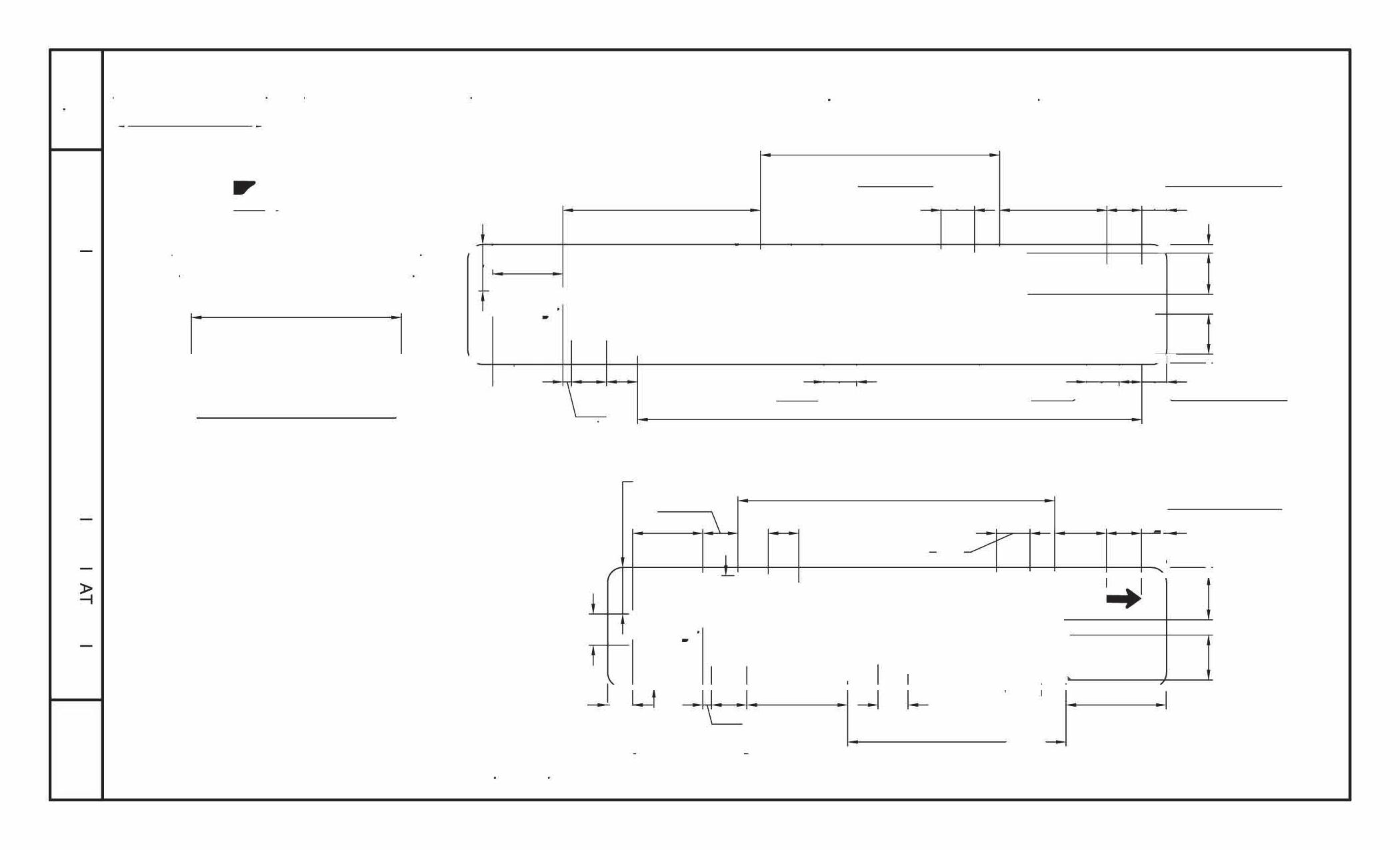


B IKE R OU TE LAN E O NLY C ENTE R LAN E O NLY C ENTE R
TYPICAL SIGNING FOR ARTERIAL AND COLLECTOR STREETS M-22.01 DETAIL N O DETAIL NO.


O BJE C T AND END O F R O AD MARKER S , C HEVR ON AND DELINEATOR INSTALLATION M-23.01 DETAIL N O DETAIL NO.

S TANDARD C LEARAN C E F O R WARNIN G S I G N S M-23.02 DETAIL N O DETAIL NO.







2 1/2"

DOUBLE CHECK VALVE BACKFLOW ASSEMBLY,
LARGER M-31.02 DETAIL N O DETAIL NO.
AND

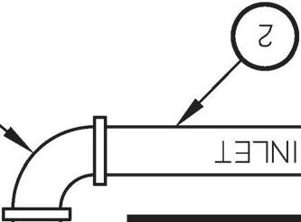

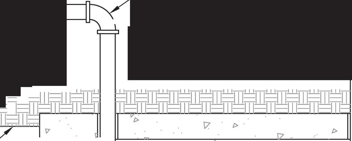

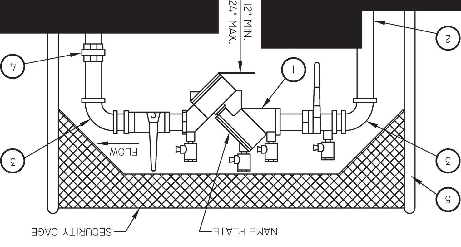
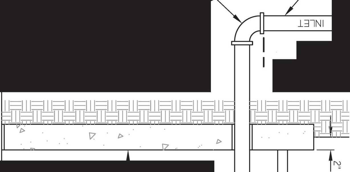



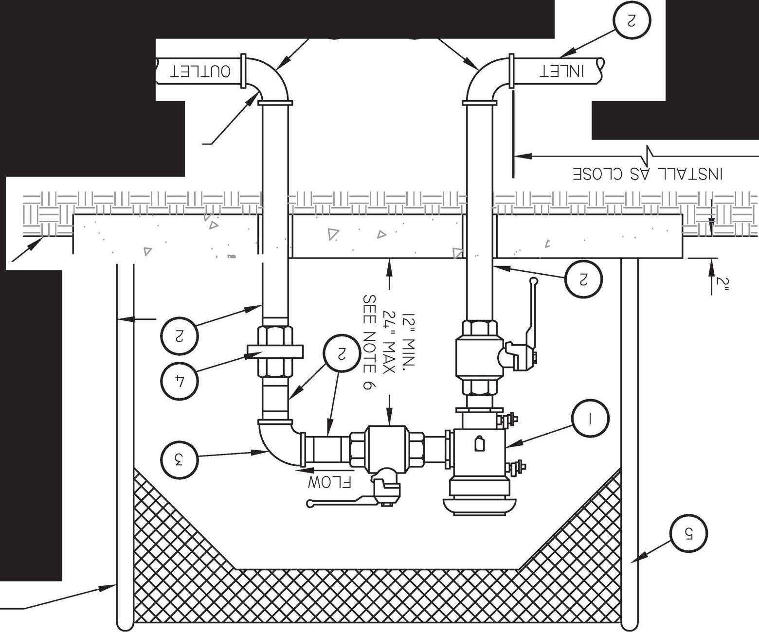


DOUBLE CHECK VALVE ASSEMBLY FOR FIRE PROTECTION SYSTEMS M-31.06 DETAIL N O DETAIL NO.



DETAIL NO. GUARD POST FOR BACKFLOW PREVENTION DEVICES M-32


DETAIL NO. GASKETED SEWER FITTINGS M-34


•• Know what's before you dig. below. Call •• Know what's before you dig below. Call •• Know wha 's before you dig below. Call AIR RELEASE VALVE/SEWER MANHOLE/WATER VALVE MARKER DETAIL M-38.03 DETAIL N O DETAIL NO.


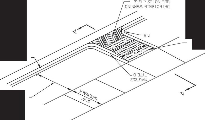


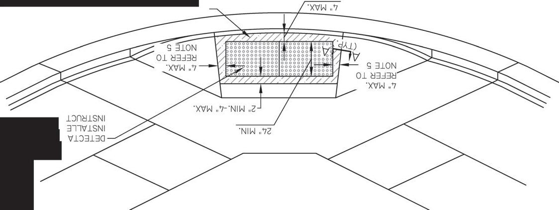
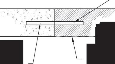


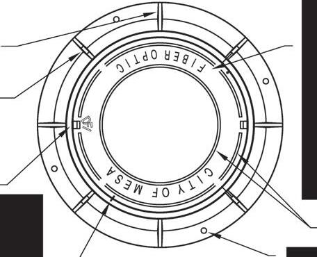

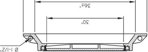





TRAFFI C S I G NAL FIBERO PTI C IN S TALLATI ON M-93.02 DETAIL N O


TREE PLANTIN G IN DE CO MP OS ED G RANITE AREA S M-103.03 DETAIL N O DETAIL NO.


≤

TURF REMOTE CONTROL VALVE ASSEMBLY
R EM O TE CO NTR O L VALVE A SS EMBLY IN RI G HTO F-WAY O R R O ADWAY M -1 09 0 1. 1 DETAIL N O DETAIL NO.


TURF
REMOTE CONTROL VALVE ASSEMBLY
R EM O TE CO NTR O L VALVE A SS EMBLY IN PAR K M -1 09 0 1. 2 DETAIL N O DETAIL NO.


