2. DIGITAL STANDARDIZATION & CODE CHECKING IN FIRE PREVENTION

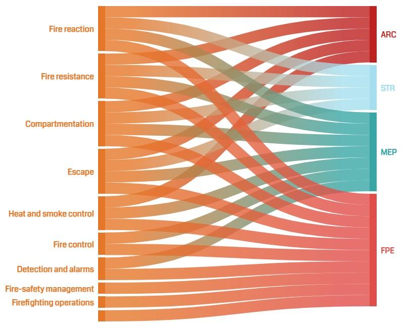
In the field of fire safety, communication between the stakeholders involved in the various disciplines and at different stages is of primary importance given the multiplicity of project teams that contribute to the definition of a fire prevention project. Figure 2 shows how the various aspects of fire prevention are of responsibility of at least two or more design teams (Amaro, 2020a) Research in recent years has shown that the adoption of a BIM approach and information standardization ensure proper collaboration between all stakeholders to properly manage the production, exchange, delivery, and verification of the information content inherent to the considered project.
The BIM approach consists of using a multidisciplinary object-oriented three-dimensional model of the constructed facility to document its design and to simulate different aspects of its construction or its operation. There are different levels of shared collaboration in a construction project: these are known as BIM maturity levels. As we move up the levels, collaboration between the various parties is increasing. Four levels of BIM maturity are currently distinguished. So far, the most common level is BIM Level 1, which encourages partial collaboration. It introduces the idea of a shared repository where all project information is collected but does not require models to be
13
Figure 2 | Interoperability relationships between several disciplines
shared between agents. The turning point is BIM Level 2, which shifts the focus to how information is shared between the various project members to ensure full interoperability. It does not require all stakeholders to operate on the same model rather everyone is free to use a separate model. What is important is the existence of a common file type that contains all the design information. Therefore, the software, which each part uses, should have the possibility to export to common file types. In conclusion, we can say that the elements of the teamwork in a coordinated way, each on their 3D model to get a federated model that maintains the specific characteristics of each design discipline. This practice of sharing information is called OpenBIM. It is a practice of sharing and exchanging information based on international standards in an open format and buildingSMART International (bSI) is the leading organization involved in the development of several OpenBIM standards, such as the Industrial Foundation Classes (IFC) (Redaelli, 2020). IFC has been steadily accepted as a standard in the industry and is the only open and relatively mature standard supported today by major BIM applications. A standard way for representing building model data is crucial in developing any stable application for building design review.
Building design review, also called Code Compliance Checking (CCC), is the procedure of checking a design against codes and standard provisions to satisfy the accuracy of the design and identify non-compliances before construction begins. The design review process is normally conducted at each phase of the design, from the conceptual to the final stage of construction documents. These series of reviews or CCC processes take a considerable amount of time and effort for both designers and building authorities. For building officials, the CCC is even more critical since they are responsible for issuing building permits to start the construction process. Over the last four decades there has been an extensive amount of research conducted in the area of automated and semi-automated regulatory compliance-checking for the AEC industry (J. Dimyadi & Amor, 2013). Automatic Code checking is a method of automatic project control. Hence, a building model should contain the information subject to review in an automatic building application and permission process. The development of BIM methodologies and neutral exchange formats have allowed the introduction of new tools for the automatic validation of rules. The data read into the IFC file is then properly managed and compared with the limits dictated by the regulations.
To initiate similar procedures in the Italian scenario of the fire prevention code compliance checking, in the following paragraphs, a careful analysis of the research launched at an international level and of the tools useful for code checking in fire prevention has been carried out to apply them to simple case studies described in Chapter 4.
2.1. INTEROPERABLE INFORMATION MANAGEMENT IN THE BUILDING PROCESS
Since the approval of Directive 2014/24/EU on public procurement the digitization of building construction processes, i.e., the use of BIM as a tool for pre-construction planning, construction, and post-construction management, has become one of the most important objectives for European Countries to make works more effective and efficient. Article 22 comma 4 of this directive states:
Digital standardization & Code Checking in fire prevention 14
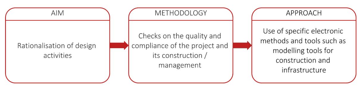
“For public works contracts and design contests, Member States may require the use of specific electronic tools, such as of building information electronic modelling tools or similar.”
(Directive 2014/24/EU art. 22 comma 4)
The legislation regulating BIM was introduced into Italian law by Ministerial Decree 560/2017 as implementation of Article 23 of Legislative Decree 50/2016 (Codice Appalti), called also “BIM Decree”. This article, implementing what is indicated in the European Directive, codified for the first time the possibility for Contracting Authority to require the use of the BIM methodology or more correctly the use of "specific electronic modeling methods and tools for construction and infrastructure". The use of such methods and tools enables Contracting Authorities to rationalize design activities and to verify the quality and compliance of both the project and the construction and management of the building (Figure 3). Thereby, the last aim of the standard is not to generate a BIM model, rather it is to manage the whole building process through digital information sharing systems.
It is logical the “BIM Decree” does not impose the use of certain open-source software on the stakeholders involved to pursuit the collaboration between them. Rather, the regulatory obligation is to activate an informative system in which information is shared through open formats to ensure proper interconnection between proprietary applications that each party may freely use. By informative system we mean the infrastructure used to manage data sharing. This means that information flows must take place within a data-sharing environment (Ambiente di condivisione dei dati), so that the information produced and shared between all participants in the project, construction, and management of the intervention can be used without the exclusive use of specific commercial technological applications.
The Italian standard identifies the sharing environment with the acronym ACDat (Ambiente di condivisione dei dati), introduced by Ministerial Decree 560/2017 and then specified in the part 5 and part 6 UNI 11337 standards while the international standard uses the term CDE (Common Data Environment) first introduced by the British standard BS 1192. This term was later adopted by international standards ISO 19650 – 1 and ISO 19650 – 2 approved by the International Technical Committee, ISO/TC 59/SC.
A Common Data Environment is a combination of technical solutions and process workflows. It is the means to manage project and asset information. It functions as a digital hub for
Interoperable information management in the building process 15
Figure 3 | Contents of Legislative Decree 50/2016 (source: Borin & Zanchetta, 2020)
project stakeholders to collect, manage and share building information models, documentation, reports, cost plans, specifications, and other project/asset information (Figure 5).
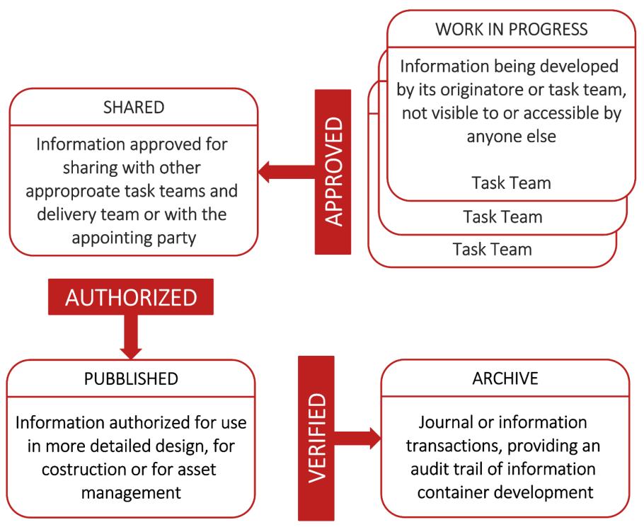
The Common Data Environment should be adopted throughout the project/activity lifecycle, encompassing both appointing and appointed parties. In addition to being a technological solution, it also includes the processes through which the information is managed, known as "workflow". It is possible to define four areas of the CDE that correspond to the same number of information content states (Figure 4):
Work in Progress, information is still being developed by the specific development team and is therefore not available to other operators yet; Shared, although information is considered complete for some disciplines, is not complete for all of them and is therefore potentially still subject to modification;
Published, information is authorized by appointing party for use; Archive that represents the History of transactions of information.
According to international standards ISO 19650 the information flow must be managed by the client or whoever handles the information on behalf of a client fulfils the role of the appointing party. Therefore, the client shall identify the information objectives of each phase of the process by drawing up a document which in Italy is called "Capitolato Informativo" (CI) and in England Employer's Information Requirements (EIR), which was replaced by the acronym "Exchange Information Requirements" with the publication of the ISO 19650 standards. It should contain the project information requirements, information delivery milestones, and information standards and identify specific procedures to produce information including its generation, delivery, and secure management. For example, when the project gets the authorization phase, which aims to obtain opinions and authorizations, the models shall provide a quality and quantity of information such that the requirements of third-party authorities responsible for releasing specific authorization documentation, and the quality and quantity of this information shall be defined by the contractor.
As a response to the EIRs, the project team and relevant bidders must supply a BIM execution plan (BEP) in accordance with the requirements. The BEP is developed in both pre- and post-types. “BIM Execution Plan pre-contract award” (BEP pre-contract award) is a document in which the tendering party expresses and specifies its method of information management of the process, in response to the requests of the appointing party. It is equivalent to the "offerta per la Gestione Informativa" (oGI) described in UNI 11337- 5. Whereas the “BIM Execution Plan” (BEP) describes from a detailed perspective the specific plans and strategies for delivering the required EIRs, specifying relevant protocols and procedures, and software and exchange formats for supporting technical aspects. It is drawn up by the winner of the tender and it is equivalent to the "piano per la Gestione Informativa” (pGI) described in UNI 11337- 5.
Digital standardization & Code Checking in fire prevention 16

Interoperable information management in the building process 17
Figure 4 | The essential structure of the Common Data Environment in PAS 1192-2
Figure 5 | The Common Data Environment
Considering the interaction between the EIRs and the BEP, the most important strategy for satisfying the information exchange requirements at each stage of the project is to define who the information is for, how it will be delivered, and what it will contain. In support of this BuildingSMART International (bSI) has developed the concept of the Information Delivery Manual (IDM). It represents a method to uniquely document the information exchange necessary for a given purpose, it describes which are the information flows and how they take place. In addition to holding a key role in public procurement for the drafting of the BEP (Jeon & Lee, 2018), it is also useful when it is a matter of obtaining authorization documents for construction purposes. In fact, through the drafting of an IDM, it is possible to highlight what information project teams need to exchange with third parties in charge of project verification. A suitable example for this thesis work is the checking process that the fire brigade authority is called upon to carry out to verify the compliance of the project with the requirements of the fire prevention code (Figure 6).
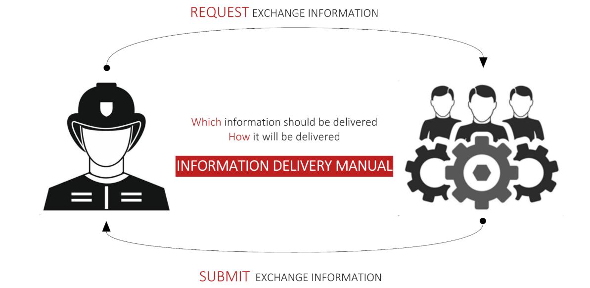
The drafting of a manual on the exchange of information between the fire brigade and the fire prevention planners would make it possible to make use of the BIM model for the verification of conformity with the fire prevention code.
The planning and realization of built facilities is a complex undertaking involving a wide range of stakeholders from different fields of expertise and lots of different tools are used in the process of design, construction, and management of a building. In such as highly fragmented process, the information exchange and interoperability are difficult to enforce. As told before, public authorities are not allowed to require stakeholders to use certain software products, for this reason, the “BIM Decree” explains the need to rely on open formats in order to make platforms interoperable. Interoperability is the ability of two systems to collaborate without errors or omissions. There are two categories of interoperability: horizontal and vertical. Horizontal or interdisciplinary interoperability is the ability of applications developed by different vendors to collaborate within a common domain. The term vertical or interdisciplinary interoperability refers to the possibility of implementing a functional and information link between different subject areas.
Digital standardization & Code Checking in fire prevention 18
Figure 6 | Exchange information process
Referring to the fire prevention discipline it is evident how the concept of interoperability is of primary importance. As shown in Figure 2 the various aspects of fire prevention are of responsibility of at least two or more design teams. For this reason, the collaboration and the updated information exchange between these teams is important (Amaro, 2020a). Moreover, even within the fire prevention discipline, the use of several software packages is often required. For example, in the case of escape routes and compartmentalization, it is essential to use building authoring software to define the structure and geometry of escape routes to be able to carry out simulations of possible fire or escape scenarios on the model using other specific software. In this sense, the lack of applications able to read open formats compares to the need to rebuild every time the spatial system in the modelling and simulation environment of the exodus or fire with a burden on the interoperability and quality of the information flow.
Finally, the “BIM Decree” emphasizes that the legislator's interest is not only to ensure that the contracting authority has a translation of the project in an open format at every stage, but that it is always able to verify the project. For this reason, it is not sufficient to require interoperability and an open data model, but it is necessary to use a structured database characterized by precise schemes and relations that can guarantee adequate verifiability of the model.
To this end, BuildingSMART International (bSI), as the leading international, nongovernmental, non-profit organization, has dedicated many years to pursues interoperability through the development of the Industry Foundation Classes (IFC) open format. The standardization activity carried out by bSI is to define the properties and relationships that characterize the building system, whether physical or virtual.
In general, the standardization problem concerns the representation of elements, the digitization of the properties defining the element, and the mapping of relations. In a representative scheme of the fire regulations, each building element must be associated with the properties of reaction to fire and fire resistance. But at the same time, it is essential to map the position of these elements in the spatial system of compartments and escape routes of the building and therefore the relationships that exist between the elements and the spaces to verify that the reaction and fire resistance properties comply with the requirements of the regulations. In this sense, the availability of a structured standard implies accessibility to a set of internal relations that guarantee greater verifiability of the same, since these relations represent the transcription of the constraints that underlie the design choices.
Besides, because IFC schema is the conceptualization of the information of the entire life cycle of an asset, it is not sustainable that every software should be able to manage such different information and data flows developed in different disciplines. In this regard bSI has developed another standard called Model View Definition (MVD) It is nothing more than a subset of the IFC schema. It serves to delimit the extension and use of IFC models to avoid software having to manage information and data flows that are not inert to the purpose for which the tools are used.
Interoperable information management in the building process 19
2.2. IFC DATA MODEL FOR AN OPEN EXCHANGE OF DIGITAL BUILDING MODELS
The international organization buildingSMART has dedicated many years to develop the Industry Foundation Classes (IFC). The IFC format was created in 1995 as a free exchange format by the work of the International Alliance for Interoperability (IAI) association, which became buildingSMART in 2008. In 2016 ISO recognized and adopted the IFC standard with the ISO 167392 standard and in 2018 updated it. Besides, buildingSMART regularly revises the definition of the standard.
The current version is the IFC4.2 schema available since 2016, but the most widely used and disseminated version is still IFC2x3 since it is referred to as the reference exchange format by several BIM protocols. However, the transition to the new version, which allows for better representation of complex geometries as it overcomes the limitations of the previous IFC2x3 release, is currently underway. IFC5 is currently in the planning and development phase.
IFC is a complex standard data model with which it is possible to represent both the geometry and semantic structure of a building model using an object-oriented approach. The building is broken down into its building components on the one hand and its spaces on the other, both of which are described in detail along with the interrelationships between them. Thanks to its comprehensive data structure, it can be used for almost any data exchange scenario in the life cycle of a building (Borrmann et al., 2018)
The bSI HTML documentation3 is the only public resource for understanding the IFC structure and follows the standard index of each ISO standard. In the initial parts, the purpose and normative references are defined, and a list of terms and abbreviations is provided. In the central part, the concept templates are illustrated and then the functioning of each class is explained. The documentation ends with a series of appendices, including a summary of the entities, diagrams in EXPRESS-G language, some examples, and a bibliography.
The IFC standard is implemented according to the EXPRESS modelling language. EXPRESS has two key functionalities: a human interface, understandable by the user through an intuitive graphic layout, called EXPRESS-G, and a machine-processable interface, partly addressed to the software and then written in machine language through a lexical form specified in ISO 10303-11 (§2.2.1)
Another language used is XML, which is generated by the EXPRESS language according to the mapping rules defined in ISO 10303-284 .
2 ISO 16739:2016 Industry Foundation Classes (IFC) for data sharing in the construction and facility management industries.
3 The last release is available in: https://standards.buildingsmart.org/IFC/RELEASE/IFC4/ADD2/HTML/
4 ISO 10303-28: Industrial automation systems and integration - Product data representation and exchange - Part 28: Implementation methods: XML representations of EXPRESS schemas and data, using XML schemas
Digital standardization & Code Checking in fire prevention 20
2.2.1. EXPRESS DEFINITION LANGUAGE & EXPRESS -G REPRESENTATION FOR IFC
EXPRESS is a conceptual schema language which provides for the specification of classes belonging to a defined domain, the information or attributes pertaining to those classes and the constraints on those classes. It is also used to define the relations which exist between classes and the numerical constraints applying to such relations (BuildingSMART International, 2016).
Attributes are the characteristics (data or behaviour) which are required to support use and understanding of the class. Attributes may be represented by simple data types (such as real, string, integer), or by other data type.
Simple data type represents the base unit of EXPRESS because a simple data type is indivisible into smaller parts. Allowed simple data types are:
REAL A decimal number;
INTEGER A whole number not containing a fraction or decimal element;
NUMBER A number that may arbitrarily evaluate to either an integer or a real;
LOGICAL A value which evaluates to TRUE, FALSE or UNKNOWN;
BOOLEAN A value which evaluates to TRUE or FALSE only;
BINARY A sequence of bits, each of which may have the value 0 or 1;
STRING A sequence of characters. Case of the character is significant.
A simple data type is graphically represented in the EXPRESS-G representation as a rectangle with a double vertical line on the right-hand side, inside which the name appears.
The other data types are:
Entity data type
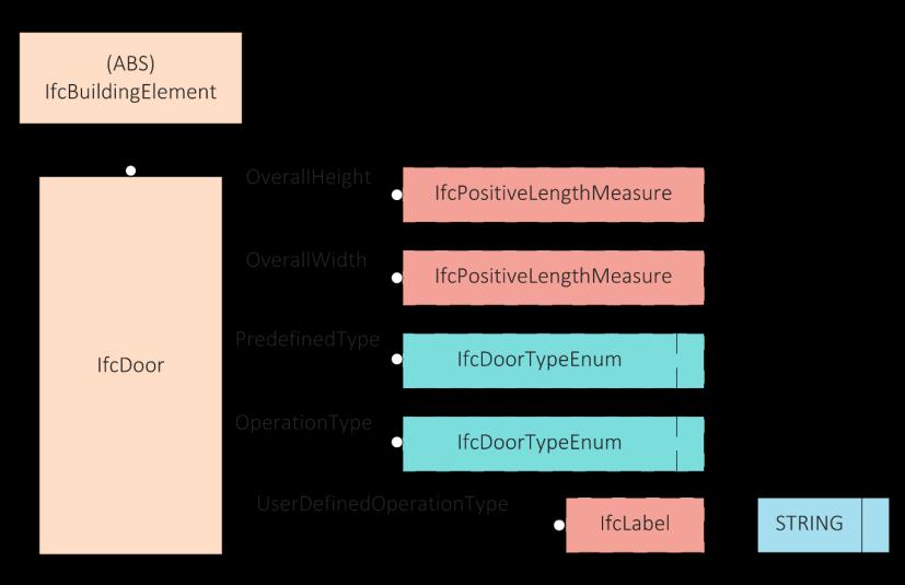
This is the most important data type in the EXPRESS language. It allows you to define realworld object classes and can be related to other entities through a sub-supertype hierarchical relationship or attribute definition. It is represented simply with a rectangle. In the EXPRESS language, entities defined as subtypes represent the specialization of supertype entities. Classes at a lower hierarchical level inherit all the characteristics of higher entities and can have other specializations by adding new instances and/or attributes. For example, the IfcWall, IfcDoor classes are subtypes of the IfcBuildingElement class because they inherit its properties and, with the addition of new instances, specialize the class. This relationship is represented with a continuous line having double thickness (Figure 8).
Enumeration data type
Enumerations are a collection of string data: for example, enumerating the opening type of a door will consist of as many strings as there are ways to open a door (Figure 8). In the EXPRESS-G graphic notation It is represented with a dotted-line rectangle with an additional dotted vertical segment to the right of the enumeration name.
IFC data model for an open exchange of digital building models 21
Defined data type
This is a data type that needs to be further specialized by other data types. For example, it can assume the characteristics of string or positive number. It is visualized with a dotted line rectangle. For example, the ifcPositiveLengthMeasure data type is used to specify the overall height of a door (Figure 8)
Select data type
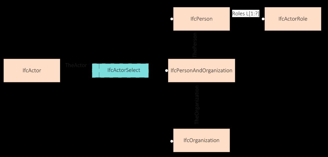
This is used in most cases to choose between different entity types. It is represented with a dotted line rectangle with a dotted vertical segment to the left of the data type name. For example, information about the IfcActor entity is provided by the attribute TheActor, which refers to the IfcActorSelect entity. This allows you to choose the type of actor between the IfcPerson, IfcOrganization, and IfcPersonAndOrganization entities (Figure 7).
Aggregation data type:
This is a datatype that represents a collection of other data types. An aggregation data type can be of type:
ARRAY: represents a collection of fixed and ordered size; is indicated by A[1:?];
BAG: represents a collection of untied elements that allows duplicates; is indicated by B[1:?];
LIST: represents an ordered collection that does not allow duplicate items; is indicated by L[1:?];
SET: represents an untidy collection that does not allow duplicate elements; is denoted by S[1:?].
Square brackets indicate the size of the collection, the first number represents the minimum size, and the second number indicates the maximum size. The character "?" indicates that the collection has an indeterminate dimension (Figure 7).
Digital standardization & Code Checking in fire prevention 22
Figure 7 | Comparison of EXPRESS representations for IfcActorSelect data type
Attributes allow you to add properties and relationships to entities. EXPRESS allows attributes to be mandatory or optional. A mandatory attribute which must be asserted is expressed by there being no prefix term before the attribute name as in the example above. An optional attribute that may be asserted is expressed by the word OPTIONAL appearing as a prefix term before the attribute name. A mandatoryattribute is represented with a continuous line, an optionalattribute is represented through a dotted line. In both cases, the name identifying the attribute is written above the line and a dot at one end indicates its main direction.
Such as attributes, a relationship, expresses a dependency or interaction, between two entities, through a cardinality that indicates the number of objects taken into account of each of the two entities that the relationship connects. Just like an attribute, the relationship is rendered graphically with a continuous line if it is required to be specified, or with a dotted line if it is optional and with a circle to indicate the main direction (Figure 9).Whereas, an inverse relationship expresses a relationship that must be described from both directions and can often be deduced from the original relationship. It is indicated by the prefix "(INV)" before the name (Figure 9).
IFC data model for an open exchange of digital building models 23
Figure 8 | Comparison of EXPRESS representations for the IfcDoor class
2.2.2. ANALYSIS OF STEP FILE AND IFCXML
Four different electronic formats can codify the IFC model (Table 1). In this thesis work, mainly two of these will be analysed: the IFC-SPF file and ifcXML file.
In the IFC-SPF file, each line typically consists of a single object together with its attributes. Opening a file with a text editor shows that it is divided into two parts: The HEADER of the file contains general information such as the IFC version and the software used, while the DATA contains all single entities (Figure 10).
Digital standardization & Code Checking in fire prevention 24
Figure 9 | Comparison of EXPRESS representations for a relationship
Format Extension Text Indexed Size STEP Physical File (SPF) .ifc Yes No 100% Extensible Markup Language (XML) .ifcXML Yes No 113% ZIP5 .ifcZIP No No 17% Terse RDF Triple Language (Turtle) .ttl based on ifcOWL Yes No 1372% Resource Description Framework (RDF/XML) .rdf based on ifcOWL Yes No 816%
Table 1 | IFC Formats (source: https://technical.buildingsmart.org/standards/ifc/ifc-formats/)
5 IFC data may embedded within a ZIP file. The embedded data may be encoded as either SPF or XML.
IFC data model for an open exchange of digital building models 25
If the EXPRESS language represents the conceptualmodel that governs the characteristics of each class, the STEP file is an instantiated model of the conceptual model and then specifies the attribute values of a given set of instances (Borin & Zanchetta, 2020)
The step file syntax is simple. Each row defines an entity by associating an ID through the "#" operator, and each entity is associated with a class through the "=" operator. Then, each entity is described by a text string with the values of its attributes.
Some values are represented with the operator "#" indicating the direction to other entities. The advantage of this method is that specific attributes are only stored once and can be used by other components through references. This makes it possible to reduce file sizes considerably.
If the value of an attribute refers to a constant in a default list from a schema entity (Enumeration definition or Select definition), it is inserted between two points in the form '. CONSTANTNAME.'.
In the IFC-SPF file, when an explicit attribute is defined as optional and an entity instance does not provide a value for such attribute, then the attribute will be marked in dollar sign “$”.
In IFC, data aggregations are supported as mentioned in §2.2.1. In a STEP file they are represented as shown in Figure 11. Collections have constraints known as cardinality which define a minimal and maximal number of elements. For exemplifying this, we may consider the IFC attribute coordinates from the IfcCartesianPoint entity. This attribute contains an ordered list of three elements: X coordinate, Y coordinate, and Z coordinate.
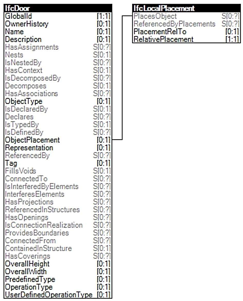
In IFC there are three kinds of attributes: direct attributes, inverse attributes, and derived attributes. The direct attributes are shown in the string of the entity to which they refer. The inverse and derived attributes do not list out directly in the entity in the IFC-SPF file but define queries for obtaining related data and enforcing referential integrity. In Figure 12 there is a list of attributes that are written under the entity IfcWall. Some of them are in black and others are in grey. Those are in black are direct attributes, those in grey are inverse attributes and/or derived attributes. In the STEP file at line #186 of IfcWall, there are nine partitions of descriptions separated by commas (Figure 13). These exactly follow the attributes shown in Figure 13. In row #134 IfcLocalPlacement does not have its inverse attribute PlaceObject, but the referring can be found in the IfcWall. An ifcXML file, on the other hand, despite its advantages in terms of readability, is larger than the SPF file. Even if IfcXML files are usually much larger than the equivalent IFC-SPF file, XML format is considered widely read, transformed, and written. Several tools and toolkits provide the support of XML. Therefore, ifcXML has been added as a valid representation of the IFC specification. And it is quite useful to implement the post-processing of ifcXML (FU, 2018)
Digital standardization & Code Checking in fire prevention 26
Figure 10 | IFC-SPF file
IFC data model for an open exchange of digital building models 27 # Attribute Type Cardinality 1 Coordinates IfcLengthMeasure L[1:3]
Figure 11 | STEP file: representation of data aggregation
Figure 12 | IfcWall in graph expression
Figure 13 | STEP file: example of inverse attribute
The full sub-element nesting expression is the basic expression in the ifcXML file for a complete IFC element. It starts with the name and its id and nests its child elements. The children could also be parents for other elements, all the children are nesting together. That means all the information will be shown together in the parent element (FU, 2018) In Figure 14 there is the same example of above. The entity IfcCartesianPoint has its attribute coordinates that is at the same time a children element, as an attribute of the entity, and parent element for its list of coordinates. Whereas in Figure 15 there is an example of inverse attribute. In this case, the id-ref pairs are used to shorten the length of the element definition, instead of nesting the entire contents of the children within the parent, some children will become separate elements alongside. IfcLocalPlacement does not have its inverse attribute PlaceObject, but the referring can be found in the IfcWall
Finally, an optional attribute, simply not shown in the ifcXML file.
Digital standardization & Code Checking in fire prevention 28
Figure 14 | ifcXML file: representation of data aggregation
Figure 15 | An inverse attribute of IfcLocalPlacement in ifcXML file
2.2.3. IFC DATA SCHEMA ARCHITECTURE
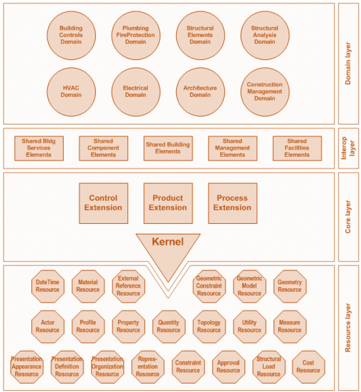
The IFC data model is both extensive and complex. To improve its maintainability and extensibility over the years, it is therefore structured into several layers: resource, core, interoperability, domain layer (Figure 16).
The core data schemas establish the most general layer within the IFC schema architecture. Entities defined in this layer can be referenced and specialized by all entities above in the hierarchy. The core layer provides the basic structure, the fundamental relationships, and the common concepts for all further specializations in aspect specific of models. It includes the IfcKernel schema that defines the most abstract part or core part of the specification. It comprises basic abstract classes such as IfcRoot, IfcObject, IfcActor, IfcProcess, IfcProduct, IfcProject, IfcRelationship. Starting from it are specified three groupings of the building process: Product Extension, Process Extension and Control Extension which are also part of the Core Layer.
The Product Extension schema describes the physical and spatial objects of a building and their respective relationships. It comprises the subclasses of IfcProduct such as IfcBuilding, IfcBuildingStorey, IfcSpace, IfcElement, IfcBuildingElement, IfcOpeningElement as well as the relationships classes IfcRelAssociatesMaterial, IfcRelFillsElement and IfcRelVoidsElement. The Process Extension schema comprises classes for describing economic computations and time schedules. The Control Extension is related to the verification of the performance of the elements during the life cycle of the building.
The two layers above (Interoperability layer and Domain layer) can reference elements in the Core Layer, while elements of the lower layers cannot reference elements of the top layers.
The Interoperability Layer lies directly above the Core Layer and represents an interoperability layer between the basic core of the data model and the domain-specific schemes. Here classes are defined that are derived from classes in the Core Layer for example the shared building elements (IfcSharedBldgElements) define the subtypes of IfcBuildingElement, which is defined in the IfcProductExtension. Those subtypes are the major elements, which constitute the architectural design of the building structure ( IfcWall, IfcColumn, IfcBeam, IfcPlate, IfcWindow).
The domain layer contains the final specializations of entities. They form the leaf nodes in the hierarchy of inheritance. The classes defined in this layer cannot be referenced by another layer or by another domain-specific schema. The domain layer organizes definitions according to AEC industry discipline (defines domains for architecture, building control, construction management, electrical systems, heating, ventilation, and air conditioning, plumbing and fire protection as well as structural elements and structural analysis)-
At the lowest level, the Resource Layer contains the basic definition classes as resources for the construction and operation of the higher levels. For example, units of measurement, materials, geometric definitions, etc. are found.
IFC data model for an open exchange of digital building models 29
IfcRoot is the most abstract and root class for all entity definitions that roots in the kernel or in subsequent layers of the IFC specification. It is therefore the common supertype of all IFC entities, besides those defined in an IFC resource schema. All entities that are subtypes of IfcRoot can be used independently, and they carry a globally unique id and optionally owner and history information. Whereas resource schema entities, that are not subtypes of IfcRoot, are not supposed to be independent entities but must be referenced by an object that instantiates a subclass of IfcRoot.
As mentioned above the most abstract class is IfcRoot. It branches into IfcObjectDefinition, IFcPropertyDefinition, and IfcRelationship. IfcObjectDefinition represents the branch of the IFC structure related to the physical, spatial, and functional objects of the building system. A second group is represented by the supertype IfcRelationship, which describes the relationships that take place within the building system. The last subgroup is the supertype IfcPropertyDefinition, used to assign properties to the elements of the model. The main difference between attributes and properties is that the first define the meaning, location, and representation of the elements, the second help to describe the performance and dimensional characteristics of the elements (Borin & Zanchetta, 2020)
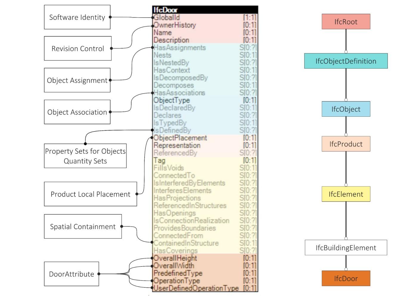
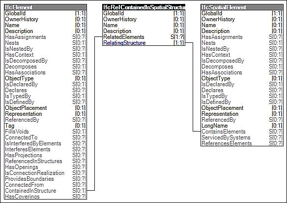
The organization described in Figure 16 is mainly used to make the IFC database easily implementable as each of its layers and sublayers represents a sector of the building process. On the other hand, the specialization of classes through a sub-supertype hierarchical relationship allows entities that are subtypes of other classes to inherit the attributes and concept templates of the hierarchically superior classes. Figure 17 shows on the right the attributes that the IfcDoor class inherits from the superior abstract classes, and on the left some inherited concept templates. Each concept template corresponds to a method that, by associating attributes to entities, guarantees the geometric, functional, or performance description of a building element(BuildingSMART International, 2020b). In practice, concept templates describe the methods of using classes for a particular BIM modeling scenario. Furthermore, as will be seen later in chapter §2.3 such concepts also form the basis of model views. As shown in Figure 18, each concept template defines a graph of entities and attributes, with constraints and parameters set for attributes and instance types. Figure 18 shows the example of the Spatial Containment method. It is used to relate the physical building elements, such as doors, to the spatial elements of a building such as rooms or building stories.
An analysis of the main entities, attributes, properties, and concept templates used to define the requirements of fire safety design of a building semantically and geometrically is given in chapter §4
Digital standardization & Code Checking in fire prevention 30
IFC data model for an open exchange of digital building models 31
Figure 16 | Data schema architecture with conceptual layers (source: BuildingSMART International)
Digital standardization & Code Checking in fire prevention 32
Figure 17
| Relationship between Concept templates, attribute inheritance for IfcDoor entity (inspired by Borin & Zanchetta, 2020)
2.3. THE INTEGRATED IDM/MVD METHOD IN THE BUILDING PROCESS
Since IFC schema provide a comprehensive specification of information from all types of organization involved in the project (architects, engineers, constructors, facility managers, etc.) and all stages in the project lifecycle. There is a need to establish, for each workflow, which are the entities, attributes, and properties that must be present for the stakeholders exchange to be successful. This is recognized within IFC development through the provision of views of the IFC schema. An IFC subset is represented by the concept of the Model View Definition (MVD) which works as an information "filter” required for a specific exchange, Today the process of elaborating a new MVD is still slow and involves the early creation of the Information Delivery Manual (IDM)6 The IDM helps to capture business processes and provides detailed specifications of the information exchanged between agents performing specific activities in this process, to ensure that the information exchanged is accurate and sufficient to carry out the activities performed by agents. The writing of an IDM supports the creation of an MVD since the first one is written in a human language while the second one is usually defined by EXPRESS or XML as a subset of the IFC. To pursue the principle of model sharing in BIM Level 2, IDM and MVD also support software vendors; by describing
6 The IDM has become an international standard with the standard ISO 29481:2010 the second edition of which was published in 2016.
The integrated IDM/MVD method in the building process 33
Figure 18 | Example of Spatial Containment concept template
an industry process that involves at least two types of application, they define which information should be shared between software.
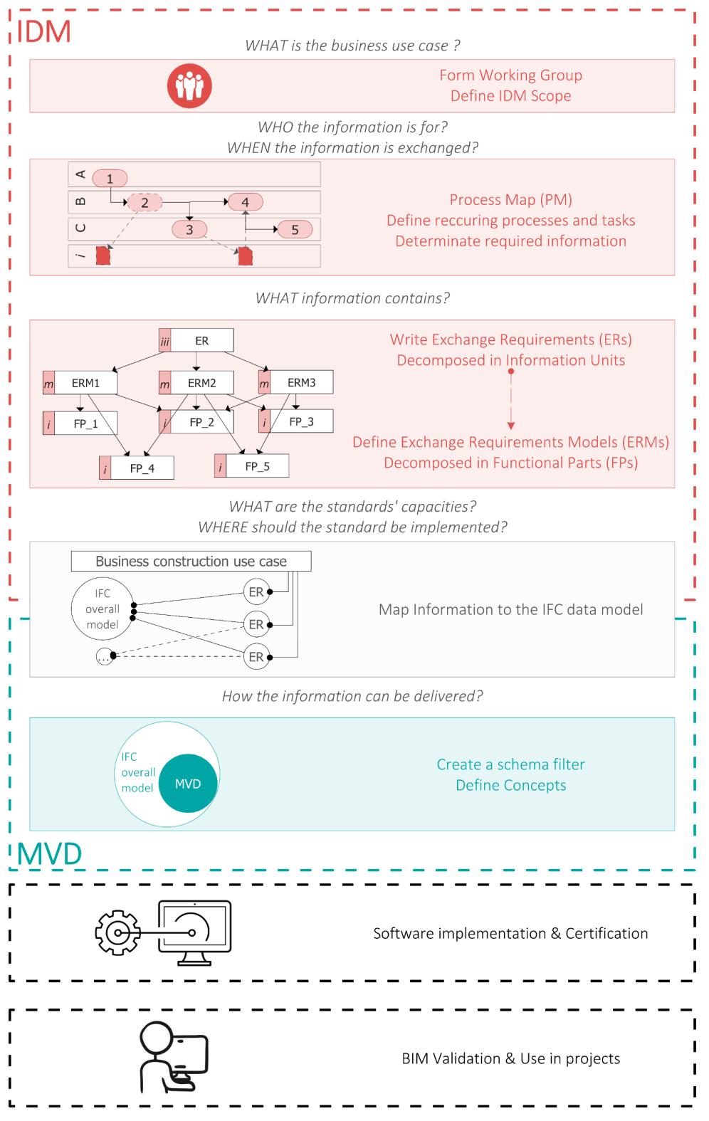
Due to the close link between IDM and MVD these two standards can be seen as parts of an integrated process (Karlshøj et al., 2012). The integrated IDM/MVD process (Figure 19) has four phases and involves several participants.
Digital standardization & Code Checking in fire prevention 34
Figure 19 | The integrated IDM/MVD process
The first step corresponds to the IDM creation process. It begins when AEC industry domain experts form a working group to develop an IDM for a specific process that would benefit from an IFC-based information exchange. Experts from the building sub-processes involved in the exchange play a key role in the IDM. One example of this is Fire Safety Professional, who requires the material supplier the definition of the fire reaction and fire resistance properties, to verify the conformity of a project with the code, or the definition of the spatial structure of a building with the classification of the spaces that belong to a compartment and those that belong to the circulation, to simulate the escape of occupants. The fire authorities themselves should also be involved in the process of establishing an IDM. Since they are the authority in charge of issuing the certificate of start of activity only after checking the compliance of the activity with the code, they should clearly define the way of delivering the information they have to check. According to the ISO 29481-1:2016, the IDM consists of process maps (PMs), exchange requirements (ERs)7 The PMs define who the information is for and the ERs specify which information is requested and exchanged.
A process map sets the boundary for the extent of the information contained within the IDM, establishes the activities within the process, and shows the logical sequence of the activities and administrative information about the exchange requirements. Business Process Modelling Notation (BPMN) is used for the process modelling and mapping the flow-oriented representations of business processes (BuildingSMART International, 2007) Diagrams of this type are organized through three elements: the actors, represented by horizontal bands named swimming lanes; the processes, possibly organized into phases, displayed through rectangles (process), the connections, to generate the information flow; the objects created in the form of models or portions of them and documents, positioned within the bands to represent the information exchanges (artefacts) (Borin & Zanchetta, 2020).
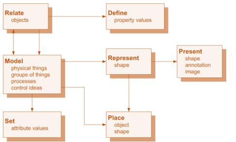
Based on the process modelling exchange requirements are defined for the interoperations throughout the process. These are normally documented in tabular, or spreadsheet applications and it describes the exchange of information in non-technical term. It is necessary to identify the information categories and sub-categories until a sufficient level of granularity is achieved so that information can be referred to as an individual attribute or a function or action within an information category. These information items are called information unit in a non-technical specification, and the functional parts provides the detailed technical specification of the information that should be exchanged in an action. Since that action may occur within many exchangerequirements, a functional part (FP) can be bound to one or many exchange requirements. Therefore, they should be specifically defined to be reusable within several exchange models. Figure 20 shows what a functional part is. Each FP defines action (or activity), like “Model”, “Define”, etc., and the object that receives the action, like a physical object, a property, a classification, etc.).
7 BuildingSMART provides standard formats to draft them, available in: (https://technical.buildingsmart.org/standards/information-delivery-manual/)
The
IDM/MVD
in the building process 35
integrated
method
Finally, a series of entity-relationship diagrams – called Exchange Requirements Model (ERM) are developed for each high-level object in the information exchange (e.g. Project, Site, Building, Building Story, Space, Wall, Door, Window, etc.). An exchange requirement model is the technical solution of an exchange requirement. It provides a complete schema that can be supported by a software application for the exchange of information for a particular purpose (Wix & Karlshøj, 2010).
The development of MVDs comprises the second stage of the integrated IDM / MVD process and they should provide how the information can be delivered. An IFC View Definition, or Model View Definition, MVD, defines a subset of the IFC schema, that is needed to satisfy one or many Exchange Requirements of the AEC industry. MVDs include three primary deliverables: MVD Overview/Description which describes the scope of the MVD, MVD Diagrams which define the MVD Concepts8 that will be used in the exchange, as well as the structure and relationships between these Concepts, Concept Implementation Guidance specifications which define the IFC entities used to exchange each concept and the Implementer agreements that generally reduce the implementation scope that would otherwise be required by the IFC schema (Karlshøj et al., 2012).
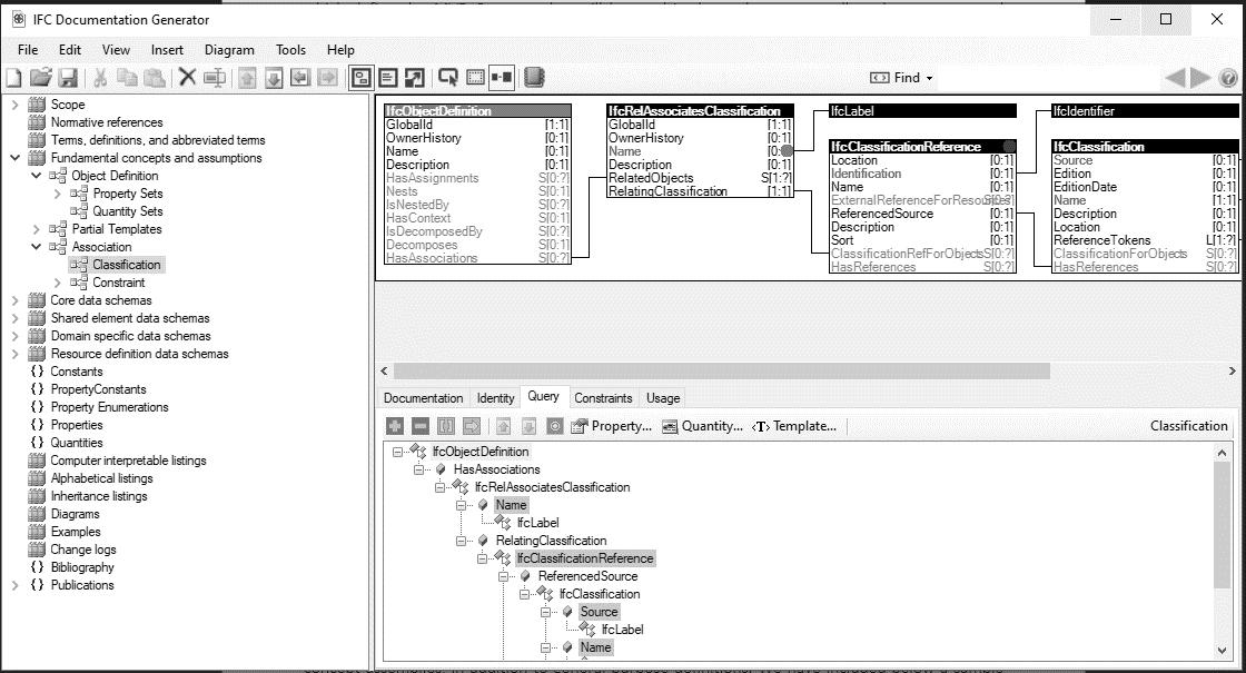
The official Model View Definitions are published by buildingSMART using the neutral mvdXML format. BuildingSMART has provided a free tool for standardizing and facilitate the MVDs elaboration and documentation named IFC Documentation Generator (ifcDoc)9 This tool providing a graphical interface for users to add entities, attributes, and constraints into concepts based on predefined ERMs (Chipman, 2012). The application automatically generates IFC entity instantiation diagrams as well as MVD documentation in HTML format. Such a tool, which is built on the IFC support schema, includes reusable model-concept assemblies, in addition to general-purpose definitions. Figure 21 shows a sample of the application screen, highlighting the Scope section, the Model
8 A Concept is backboned by ConceptTemplates (§2.2.1), which are defined independent from ModelViews and provide definitions for more generic relationships and rules and can be applied to different IFC entities to develop specific Concepts.
9 A description of the tool is available in: https://forums.buildingsmart.org/t/ifc-documantation/1454/11
Digital standardization & Code Checking in fire prevention 36
Figure 20 | Functional parts (source: Wix & Karlshøj, 2010)
Concepts, and the four-layer of IFC architecture system (§2.2.3) which contain entities, attributes, property
In the current bSI Online Database the main MVDs released and implemented within most software are:
Coordination View Version 2.0, which is an MVD of IFC 2x3 whose purpose is to allow sharing of building information models between the major disciplines of architecture, structural engineering, and building services (mechanical). It contains definitions of spatial structure, building, and building service elements with shape representations, including both, parametric shapes for a limited range of standard elements, and the ability to also include non-parametric shapes for all other elements. Property sets, material definitions, and other alphanumeric information can be assigned to those elements.
Reference View (RV 1.2), an MVD of IFC4, in addition to supporting coordination between models, visual and computational interference checking, has been created to make possible the construction of metric calculations and construction schedules. Therefore, all elements are represented through the use of mesh surfaces and translation solids to guarantee an adequate representation of the volumes.
Design Transfer View (DTV), an MVD of IFC4, has the objective of guaranteeing the transfer of design information from one software to another, thus making subsequent integrations and extensions possible. Such applications enable inserting, deleting, moving, and modifying physical building elements and spaces.
The
in the building process 37
integrated IDM/MVD method
Figure 21 | IfcDoc screen
On the basis of what has been said and given the intrinsic interconnection of the disciplines on the subject of fire prevention, Design Transfer View (DTV) is today the most useful MVD for carrying out exports from building modelling software to analyse the consistency of the IFC model with respect to subsequent code checking operations.
Once an MVD is set up, it cannot be used in projects until it is supported by at least two software applications - the sender and the receiver of the exchange. The implementation of the MVD within a software application is fundamental but not sufficient to guarantee end-users a reliable exchange of BIM information in their projects. To ensure this reliable data exchange, software certification tests should be done exporting some test cases (BIM) and checking each object instance against the requirements defined in the IDM/MVD. This last step is also known as BIM validation (Karlshøj et al., 2012)
2.3.1. RESEARCH IN THE FIELD OF FIRE PREVENTION
BuildingSMART has launched a project focused on enabling the open exchange of information to provide better fire safety decisions in building development and management. It includes the development of two Model View Definitions (MVDs) to support Occupant Movement Analysis (OMA) and Fire Safety Engineering (FSE) in the IFC BIM model. The project team, consisting of multinational professionals, was formed after identifying a lack of support within the current IFC model for OMA and FSE. The current team is mostly spread across Europe and it consists of people from Autodesk, accurate GmbH, Briab, IST GmbH, Technical University of Munich, University of Greenwich, VIB e.V., LAB University of Applied Sciences, and Foster + Partners. It brings together fire safety engineers, regulatory experts, fire modelling professionals, evacuation modelling professionals, fire model software developers, evacuation model software developers, and people movement analysis experts10 .
The focus of this project is on OMA and FSE but another project proposal with a focus on the prescriptive fulfilment of requirements is in the pipeline11 . The second project is the IDM/MVD General Fire Safety Requirements which is led by KIT, DTU and buildingSMART Germany. The objectives of this second proposal are to test whether buildings can exceed the RQs of building regulations using an IFC sub-scheme "MVD for General Fire Safety Requirements".
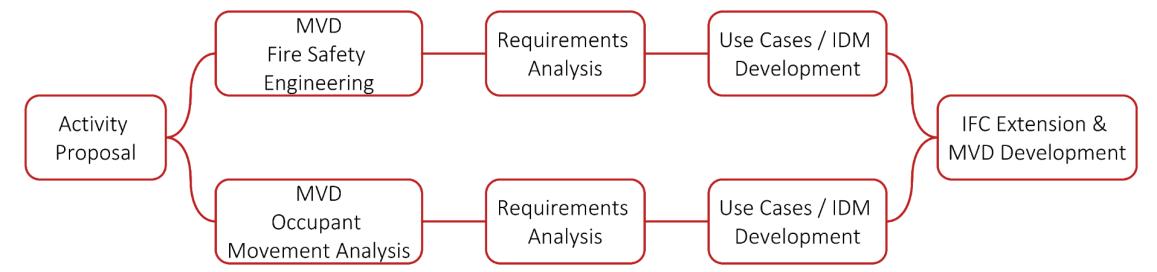
Figure 22 shows the roadmap of the research team of the first project12 which are now on the requirements analysis phase. They are analysing regulatory requirements, smoke, and fire simulation requirements and evacuation modelling and occupant movement requirements since the
10 Fire Safety Engineering & Occupant Movement openBIM Standards (source: https://www.buildingsmart.org/standards/calls-for-participation/fire-safety/)
11 Max (KIT), Karlshoj (DTU), and Bekboliev (buildingSMART Germany) will allow to identify what are the information to be mapped for the prescriptive code checking taking into account local regulation (danish and german regulation) and European and international standards.
12 The tool that they are using is BuildingSMART use Case Management Tools which is a platform for documenting IDM (https://ucm.buildingsmart.org/)
Digital standardization & Code Checking in fire prevention 38
research is mainly focused on performance-based design which basically consists of fire safety engineering analysis and occupant movement analysis. These two topics are closely linked because for the first one you should calculate how far the fire or smoke spreads inside the building and for the second you should calculate the escape time of the occupants who are inside the building and must get out in time to avoid fatal accidents. The research team has decided to produce two separate MVDs because even though these two topics are closely related, there is a lot of information to exchange.
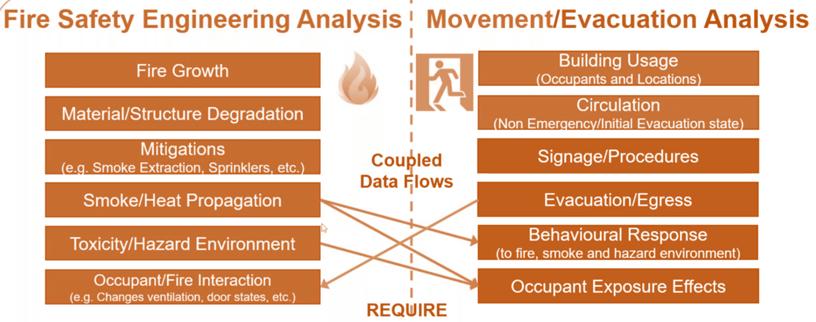
From the analysis of this work, the research team with the acronym FSE associated with the first of the two MVDs intensified the theme of fluid dynamic computation belonging to the wider discipline of Fire Safety Engineering which instead also includes the theme of evacuation simulations (Figure 23). Therefore, the idea of proposing two separate MVDs can be useful to better frame what are the requirements connected to the two type of analysis13 but it would be correct to define a Master MVD which is explicative of FSE intended as a discipline for fire prevention purposes since the analyses connected to it are interconnected. The engineering-performance approach is based on the prediction of the evolutionary dynamics of the fire through the application of calculation models by evaluating the safety levels in relation to specific fire scenarios, the characteristics of the spaces, the behaviour of the occupants and their state, the type of activity and the management system.
13 In this regard, we mention the research conducted by Spearpoint in 2006 and Dimyadi in 2007 at the University of Canterbury on how to generate FDS Fire Simulation Input using IFC-based Building Information Models. They began by assessing what information was required by some fire simulation software and then sought to identify how to map this information into an IFC model
39
The integrated IDM/MVD method in the building process
Figure 22 | BuildingSMART MVDs proposal raodMAP (inspired by: https://vimeo.com/483080281)
Figure 23 | Fire Safety Engineering Regulations or Performance-base design (source: https://www.buildingsmart.org/standards/callsfor-participation/fire-safety/)
In the domain of fire safety engineering the relationship between BIM authoring tools and simulator software is fundamental in the overall life cycle of the building. The two types of tools must therefore be able to exchange information (Figure 24).
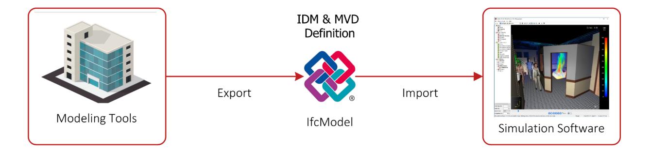
The research team has started to analyse simulators to understand what types of objects and properties they need for simulations and whether they support IFC import (Table 1). Most currently available simulators rely heavily on importing geometry from IFC but do not automatically import a lot of information from IFC model. Standardising information improves data exchange for these tools but is important to understand what information coming from the simulation makes sense to implement in IFC model, remembering that even if an integration of the IFC model is possible it is fundamental not to proceed with unnecessary implementations.
Fire Modelling tools
PyroSim (Thunderhead Engineering, USA)
SMARTFIRE (FSEG, UK)
KOBRA-3D (IST GmbH, Germany)
Evacuation and Circulation Modelling tools
BuildingEXODUS (FSEG, UK)
crowd:it (accu:rate, Germany)
ASERI (IST GmbH, Germany)
Pathfinder (Thunderhead Engineering, USA)
MassMotion (Oasys, UK)
STEPS (Mott MacDonalds, UK)
Legion (Bentley, USA)
Pedestrial Dynamics (INCONTROL, Netherlands)
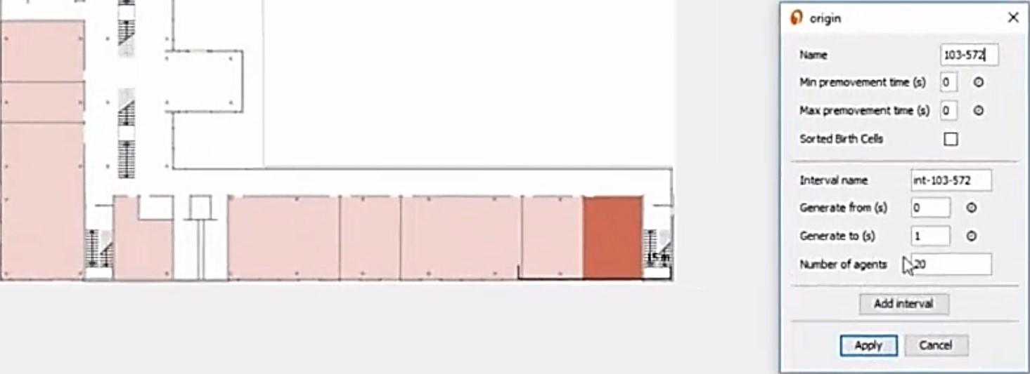
it is worth mentioning the work done by Abualdenien et al in 2018 aimed at developing an MVD for checking fire-safety and pedestrian simulation requirements. To simulate the evacuation, the crowd:it software14 was used (Figure 25) The simulator is capable of analysing the pedestrian flow and movement patterns, evaluating the building against safety concepts as well as its performance during a particular event or worst-case scenarios. Pedestrian simulators are mainly interested in boundaries, spaces, transport elements, and exits. Besides the geometry of the elements, additional information is required, including, the escape routes, spaces maximum number of occupants, the demographics of the occupants, the stairs number of treads, or riser height…etc. Using IfcDoc, they built over the commonly available MVDs, including coordination, reference, and
14 The tool is available at this link: https://www.accu-rate.de/en/software-crowd-it-en/
Digital standardization & Code Checking in fire prevention 40
Figure 24 | BuildingSMART MVDs proposal to connect BIM authoring tools and simulator software
Table 2 | Software with IFC file import capability
design transfer views, a new one MVD. Then, they took a use case, exported some properties like the number of occupants, and then put the file in the software for simulation. The geometry, spatial structure, and simple properties like the number of the agent in the room were able to import into the simulator but then they had to build the path for evacuation manually because they could not find any property on the IFC to write this information. After this, they initiate the simulation, but such as work stopped here because the file obtained from the simulation is very large and it included a lot of information difficult to implement inside an IFC model.
2.4. AUTOMATED CODE COMPLIANCE CHECKING IN FIRE PREVENTION
The checking of building design against standard codes and regulations is time-consuming and error-prone because authorities conduct manual certification processes and due to the increasing complexity in both the building specifications and the building regulations
Advanced countries, where the delivery of the BIM data is mandatory, are promoting automated checking compliance with the regulation because it can reduce errors, time, and the inefficient use of human resources. Automated rule checking is a procedure to assess a project, against regulations to satisfy the design completeness and identify non-compliances, relying on the configuration of objects, their relations, and attributes of a BIM model. A common approach to automatic compliance checking is object-oriented systematic comparison, i.e. the comparison of each object or system in the representation of a building model with the constraints of a standard (J. Dimyadi & Amor, 2013). The output is usually a list of non-compliant objects. This method requires:
- A database - in effect the BIM;
- Rule sets - in effect the building regulations to be applied;
- A rule engine - an application that creates queries from the rule sets and run these against the database.
Over the last four decades there has been an extensive amount of research conducted in the area of automated and semi-automated regulatory compliance-checking for the AEC industry (J.
Automated Code Compliance Checking in fire prevention 41
Figure 25 | IFC import file in Crowd:it (source: Abualdenien et al., 2018)
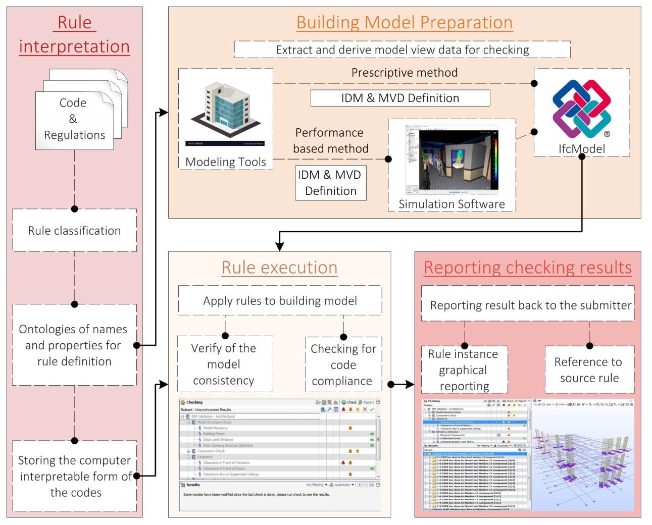
Dimyadi & Amor, 2013) In 2009, Eastman et al. reviewed five applications of existing15 commercial tools to present the state of art in the automated rule-checking domain and to define the stages of the rule checking process. The overall process can be broadly structured into four stages (Figure 26) Rule interpretation and logical structuring of rules for their application
Regulations can be prescriptive, or performance based. Performance-based regulations are formulated as legal text, open to interpretation and discretionary use. The representation of these regulations as computable objects is challenging. Prescriptive codes have the advantage of being formulated as rules, with quantified measures to which technical solutions must conform, and are consequently easier to represent as computable objects (Holte Consulting, 2014). The regulatorycompliant design of a building, regardless of whether it is based on prescriptive or performancebased codes, is usually preceded by data collection through a building code analysis. This is a systematic process of manually collecting information concerning the regulations and entering it into a spreadsheet or predefined form. First, all the necessary concepts and attributes must be extracted (J. Dimyadi et al., 2014). Then the translation of contents of the codes and guidelines into a form that allows computer processing should be done since rules for building design are first defined by people and represented in human language. The complexity in representing regulatory texts as computable objects is one of the factors attributed to the slow progress in the field of code checking (J. Dimyadi & Amor, 2013).
15 The Singapore CORENET project (COnstruction and Real Estate NETwork) by Singapore's Ministry of National Development started in 1995. One of the tools developments is CORENET e-PlanCheck which performs automated checks against Singapore codes on building control, barrierfree access, fire prevention, environmental health, households, public housing, and vehicle parking. To check code compliance, the team developed the semantic objects in the FORNAX library which is base on IFC and involves IFC extensions. CORENET rule checking is performed in three phases: checking rules with current IFC information, checking rules with property set extensions to IFC, and checking rules with derived information from IFC (Eastman et al., 2009). Norway adopted CORENET's e-PlanCheck and tested it. Then, the HITOS (Tromsø University College) project driven by Statsbygg (Norwegian Directorate of Public Construction and Property) performed spatial requirement and accessibility checks using dRofus software and the Solibri Model Checker(SMC). This project suggested a six-stage standardization process: definition of scope and source for the rule set, computability assessment, committee assessment, logic rule notation, selection of rule format, and implementation of the rule in rulechecker software (Lee et al., 2016). DesignCheck (2006) is an automated code-checking system for the Building Code of Australia. It provides a shared object-oriented database approach using the EXPRESS Data Manager (EDM) platform. It supports the development of rule checking using the EXPRESS-X language For the initial feasibility assessment, the Australian Standard 1428.1 “Design for access and mobility” was encoded with EDM rule schemas (Lee et al., 2016)
The International Code Council's SMARTCode (2006) project was developed to automate code compliance checks for I-Codes and federal and state codes. The SMARTCode builder software provides an interface to mark the entities required for a code check. Information about the extracted entity is collected in a STEP file and converted using XML schemas. The US GSA (General Services Administration) and US Courts (2007) have supported the development of design rule checks for United States federal courthouses, which is an early example of a rule check applied to automated design guides. In this project, the research team parameterized circulation and security rules to develop parametric rules executable in an SMC plug-in.
Digital standardization & Code Checking in fire prevention 42
Building model preparation
In this phase, what information is required for checking, and what data format should be used for information exchange need to be defined (Holte Consulting, 2014) Building models involve large datasets, hence separate model views are used to both derive the needed data required for a specific type of rule checking and to extract subsets of an overall building model allow more efficient processing. The mapping of information requirements for code checking is addressed in general with the IFC format. In this regard, the writing of an Information Delivery Manual (IDM) and then the drafting of a Model View Definition (MVD) described in §2.3 allow to identify which entities, properties and attributes must be mapped within a model view for the checking execution to be successful. Sometimes the data model IFC does not cover all the information and it is necessary to input new property or derive them from the existed one. However, since the aim is to keep the manual input of new properties to a minimum, you first try to understand whether certain information can be derived from others rather than creating new ones (Kincelova et al., 2020) For example, FORNAX™, which is the base implementation of CORENET ePlanCheck contains an objects library that extends the IFC Schema to capture needed building code information and to facilitate the implementation of building checking. Each FORNAX object has several functions to retrieve required properties from IFC data; in fact, CORENET rule checking is performed in three phases: checking rules with current IFC information, checking rules with property set extensions to IFC and checking rules with derived information from IFC (Eastman et al., 2009)
Rule execution
This phase carries out the checking and brings together the prepared building model with the rules that apply to it. A syntactic pre-checking of the model is necessary to determine if the properties, names, objects necessary for checking are available from the model. Hence, the actual rule execution becomes relatively straightforward if the rules have been interpreted into computable forms consistent with these data available in the building model. Some rule checking involves implicit properties, such as the floor area in rooms, the narrowest width in a passageway and accessibility for the handicapped; other properties of a design being checked are performance-based, requiring analysis or simulations for their derivation. Performance-based rules generally require a specially derived model view, with its own geometry, material, or other properties, as input for executing the analysis/simulation. The analysis results are combined with the modelling assumptions to determine the adequacy of the rules (Eastman et al., 2009)
Reporting checking results
The parameters of the local instance and the text defining the violated rule are the basis for reporting. A graphical reporting of the rule instance may also be useful to better understand the origin of the error.
Below we review a collection of studies carried out over the last two decades that attempt to define strategies for closing the gap between the terms used in rules to be checked and the information explicitly represented in the target building model.
Automated Code Compliance Checking in fire prevention 43
2.4.1. RULES CLASSIFICATION
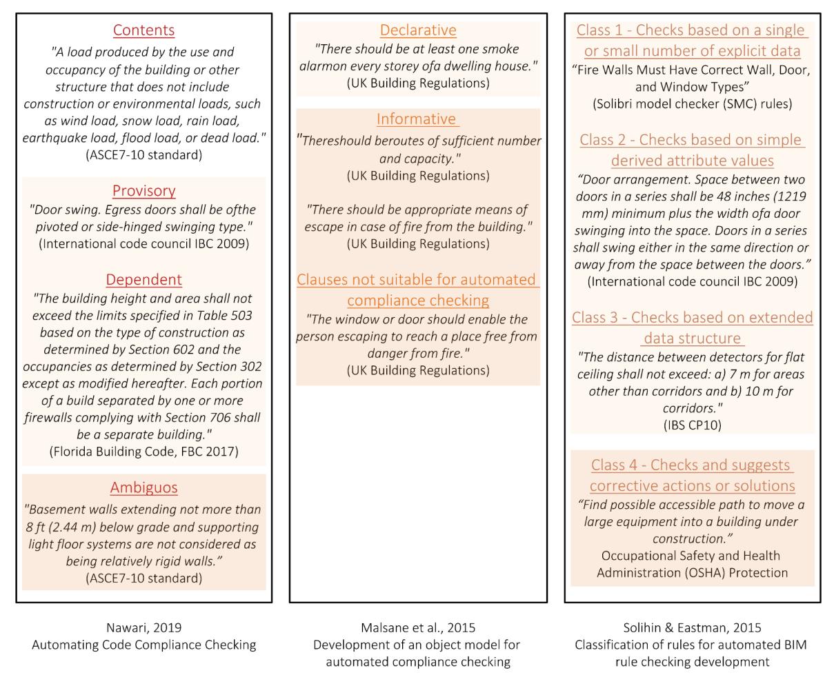
The translation of the requirements of building codes poses a great challenge, as these could not be more diverse and abstract. The rule interpretation phase starts with the classification of the regulation clauses to select the categories that can be treated in the process. Ontology of names and properties rule translation typically has two aspects: the condition or context where the rule applies, the properties upon which the rule applies. For example, the first might identify potential fire exit paths, and the second would then check the width and length of the identified paths (Eastman et al., 2009). The research carried out so far has proposed various methods of classifying rules (Figure 27).
Digital standardization & Code Checking in fire prevention 44
Figure 26 | Code Compliance Checking process
In 2019, Nawari proposed a definition of four different categories of clauses:
- Contents, which are the sections of the building codes and regulations that cannot be transformed into object rules because these clauses are usually definitions, such as the definition of types of loads, firewall, fire rate, smoke evacuation, etc;
- Provisory class concerns clauses that can be transformed from the textual format into a set of rules based on objects. Examples of such clauses are prevalent, and typical structures include rules with specific values such as those given in tables or equations in the building regulations;
- Dependent clauses define the dependent regulations on one or more propositions and define specific conditions. Dependent clauses specify that one clause is reliant on one or more other provisions. This means that some requirements are only appropriate for a specific condition when other clauses are satisfied. These clauses are often challenging to transform into sets of immediate object rules;
- Ambiguous provisions are vague or inexact and not capable of being computerized. Some of them may have to be rewritten to enable implementation in an automated compliance auditing environment.
Automated Code Compliance Checking in fire prevention 45
Figure 27 | Rules classifications review
The provisory and dependent clauses proposed by Nawari have similar meaning of these defined as declaration clauses by Malsane in 2015 He makes a distinction between clauses that declare information unambiguously (declarative), those that are informative, and those that are not suitable for automated compliance checking. Declarative clauses are short in length, clear in their meaning, and can be reinterpreted easily into a form that can be computer processable, thus suitable for automated compliance checking. These clauses contain entities with clearly defined attributes and constraints. Conversely, informative clauses are subjective and contain data only partially suitable for interpretation into computer rules.
Another kind of classification is made by Solihin & Eastman in 2015 They proposed four general classes of rules. The rules belong to the first class require a single or small number of explicit data and the information is explicitly available from the model either directly from the entities or they can derive using relationship entities. The second class of rules is based on simple derived attribute values without creating new data structures. It involves a trade-off between requiring the user to derive the data and verify the derived data. It is necessary to derive data because BIM models do not usually capture this explicitly. For example, the length of the escape route requires arithmetic or trigonometric calculations, such as finding the straight-line distance between two points. Many IFC supporting tools as Solibri Model Checker (SMC) are already capable of trigonometrically creating simple geometries. The rules within class 3 require an extension to the data structure encapsulating higher-level semantic conditions of building data. To be able to solve rules in this class, software relying on geometrical, topological, and other properties and algorithms such as shortest path may be involved. The last class of rules is a collection of rules that do not strictly ask for compliance or non-compliance, but rather it requires a “proof of solution”. The rules usually focus more on how the building model proves compliance rather than merely fulfilling prescribed criteria. It generally represents performance-based codes or other similar rules. This last class could be similar to the ambiguous class of Nawari and Informative and not suitable for automated compliance checking of Malsane.
2.4.2. RULE-MAKING APPROACHES
So far, the main commercially available solutions for automatic control based on BIM apply the rules to the IFC building model data. This means that objects and their related parameters must be searched for within the IFC schema. Rule construction is generally challenging in terms of computing expertise. The two most widely used checking applications are Solibri Model Checker (SMC) and CORENET. They are so-called black box systems because in both the rules cannot be changed or customized without the cooperation of the suppliers (Borrmann & Preidel, 2018) Below some rules related to code checking in fire prevention are reported.
Solibri Model Checker
The Solibri Model Checker (SMC) is a java-based desktop platform application including a variety of built-in functions such as a library of capabilities for pre-checking a model (name and attribute conventions, object existence, and others… ), automatic viewing of checking issues, for use
Digital standardization & Code Checking in fire prevention 46
in reporting, rules for accessibility checking, rules linked to the fire safety, etc. Rules can be parametrically varied through table-set control parameters. However, as told before, the rules in SMC do not allow to freely manipulate data to generate new properties16 and the user cannot create new rules, but for a particular compliance checking task, it is possible to group several built-in rules into a new folder. In 2016 a group of rules were created to check the compliance of fire safety according to Danish regulation BR10 for initial design (Taciuc et al., 2016). Rules were divided into three parts taking into consideration the checking that will be performed:
- Design of Escape Routes;
- Fire Compartments and Fire Sections;
- Additional Rules.
The ruleset regarding the design of Escape Routes included checking of: Door minimum dimension, stair minimum dimension, internal passages width, escape route analysis, and rescue openings. The escape route analysis rule checks whether it is possible to exit safely from the building in case of fire or other emergencies. This rule uses three different classifications17:
- Exits classification is used to identify the exits of a building specifying which doors are the exit doors;
- Space Usage classification is used to specify which spaces are e.g., Offices or Meeting Rooms and set specific maximum distances for them in rule parameters.
- Vertical Access classification is used for identifying stairs and lifts. You can specify which spaces are lifts if your exit routes allow them.
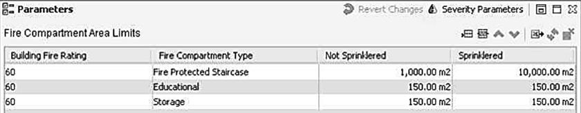
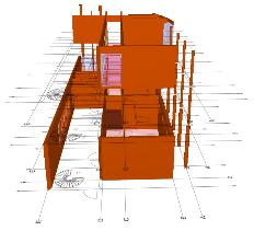
The ruleset on Fire Compartments checks separately for walls, doors, and windows if they have the required fire property and if that property has the correct value18 Another rule checks that spaces must be included in fire compartments19, and if space is set to be a fire exit space, it must have a fire exit door. The last check in the ruleset is that area of all fire compartments is less than a given maximum value. For this ruleset Fire Compartment definition must be made in Solibri The Compartmentation View allows you to visualize, add, edit, compartments in the model. Properties dialog for Fire Compartments root gives the possibility to specify the Building Fire Rating and to filtered how much of the compartment is sprinklered.
16 Entirely new rules are added in java using the SMC application programming interface (API) The API interface is not publicly available, restricting the rules to be checked to those supplied by Solibri.
17 Description of the rule at the following link: https://solutionhelp.beta.solibri.com/help/smc/9.6/en/Help.htm?html_checking.htm
18 Description of the rule at the following link: https://solutionhelp.beta.solibri.com/help/smc/9.6/en/Help.htm?html_checking.htm
19 Description of the rule at the following link: https://solutionhelp.beta.solibri.com/help/smc/9.6/en/Help.htm?html_checking.htm
Automated Code Compliance Checking in fire prevention 47
Another approach used for rules construction is that of the EXPRESS Data ManagerTM (EDM) server. It provides an object database and supports the open development of rule checking using the EXPRESS-X language20, which is the language in which the IFC model schema is written (Zhang et al., 2014). The EDM contains data models and schemas, including model schemas, rule schemas, and query schemas. In particular, rule schemas define rules to validate data models using the EXPRESS language and define entities, rules, functions, and procedures based on the building code.
The two approaches described above depend on proprietary software. Other research uses the method of MVDxml released by Building Smart. The mvdXML is an open standard to define model subsets and validation rule-sets (Chipman et al., 2016). An mvdXML file is developed by the official IfcDoc tool21 as well as by common XML editors. The purposes of mvdXML are to limit IFC scopes to subsets, to generate MVD documentation, and to define validation rules. mvdXML approach is called
20 In the STEP standard, the EXPRESS-X (ISO10303-14, 1999) is provided as an extension of EXPRESS includes extra constructs to map model views and define additional constraints. EXPRESS and EXPRESS-X can be interpreted by some IFC validators such as the one built into the Jotne EDM Model Server.
21 With IfcDoc tool we can develop an MVD to define a subset of IFC or an MVD rules to control the model by inserting constraints.
Digital standardization & Code Checking in fire prevention 48
Figure 28 | SMC Rule: Fire compartment area must be within limits (source: Solibri Model Checker Help)
Figure 29 | Compartmentation View in SMC (source: Solibri Model Checker Help)
white-box system, which can be configured individually by each user. The validation rules can be categorized as follows (Zhang et al., 2014):
1. checking existence of attribute values and referenced entities, size of collection data types, and cardinality;
2. checking content of values, including the value of simple data types and collection types;
3. checking uniqueness of values;
4. checking the if-then conditional dependency. This is based on the checking results of the previous.
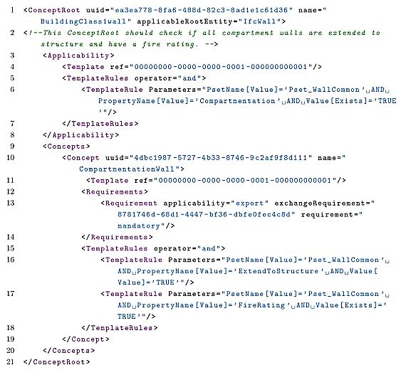
An example of this is shown in Figure 30 where the existence of properties FireRating and Compartmentation of Ifcwall entities is checked (Pfuhl, 2018)
Finally, some research also explored the visual programming for rule construction. Information systems, which are described by a visual language can be interpreted much faster and easier by humans and make the overall process of compliance checking visible. Visual languages are often also called flow-based since they represent the complicated structures as a flow of information (Preidel & Borrmann, 2015) Preidel & Borrmann shown an example of this approach considering a rule belong to the German Standard. It says: «depending on the height of the room, the height of the smoke layer and the fire classification, the guideline requires a minimal smoke ventilation area that is listed in a
Automated Code Compliance Checking in fire prevention 49
Figure 30 | Requirements to Fire Walls as mvdXML Code (source: Pfuhl, 2018a)
data table». The translation of this regulation is shown in Figure 31 as a VCCL-graph. In this processing graph, a single room is considering, and afterward, its attributes are used to capture both the actual value and the value required by the standard. The result of this check is the comparison of these values, to check whether the limit value is met or not.

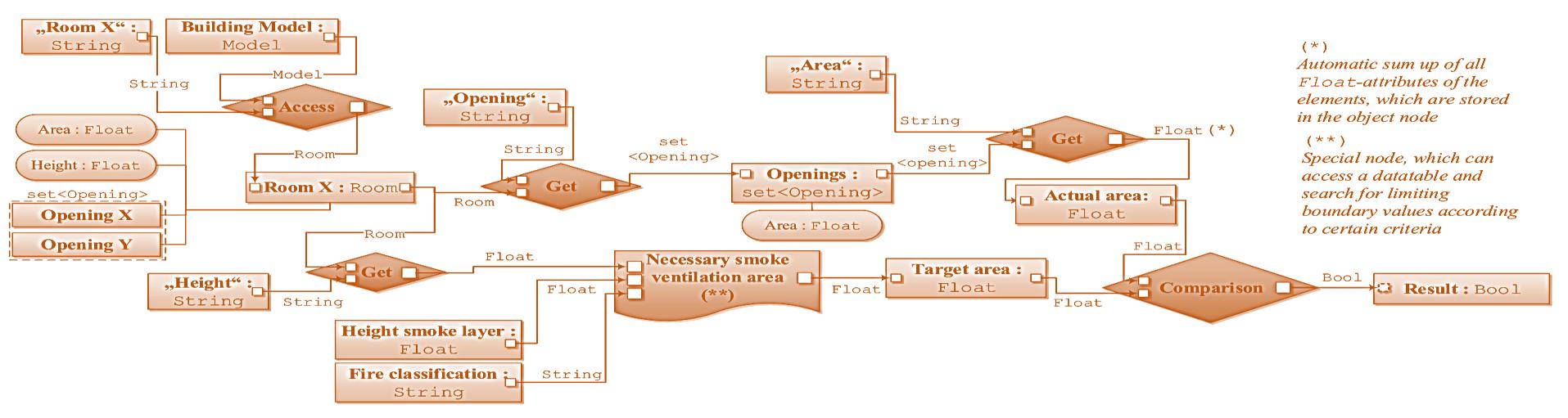
The same approach has also been applied in other research projects using the Visual scripting tool Dynamo of Revit. Harrell & Mathews showed a script to automatically calculate the occupancy loads, whereas creating a door schedule revealed non-compliant door types using conditional formatting within Revit (Figure 32).
In 2017 Vermeulen proposed a method to automatize the definition of the shortest routes between a room exit and the nearest emergency exit using Dynamo. For the record it must be said that Revit 2020 has introduced the travel route tool to help measure travel distance requirements
Digital standardization & Code Checking in fire prevention 50
Figure 31 | VCCL graph (source: Preidel & Borrmann, 2015)
Figure 32 | Conditional Formatting Used to Demonstrate Compliant Doors (source: Harrell & Mathews, 2018)
even though the travel route tool is not capable of calculating vertical distances, i.e., it does not work on stairs22
Also, Kincelova et al. in 2020 have used the Visual scripting tool Dynamo of Revit. The research provides the example of fire resistance rating check of the walls and the check of continuity of fire separations (Figure 33) The Dynamo script for the continuity of fire separations managed to cover both structural and non-structural partitions and walls. However, it could not take into consideration the continuity of suspended ceilings or other vertical elements. This script is limited to checking the continuity of fire separation boundaries. However, it does not yet address the integrity of the fire separations in terms of the protection of openings (e.g., dampers).
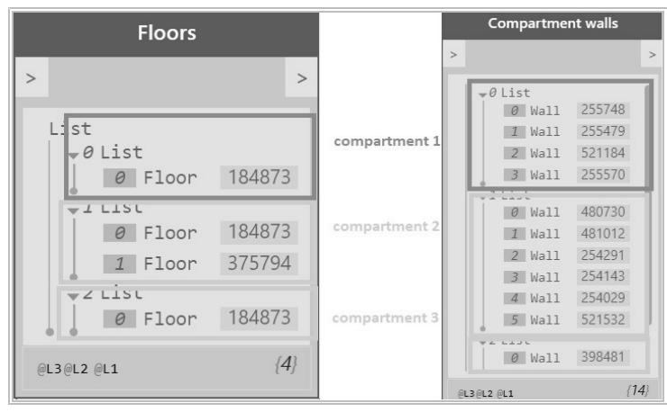
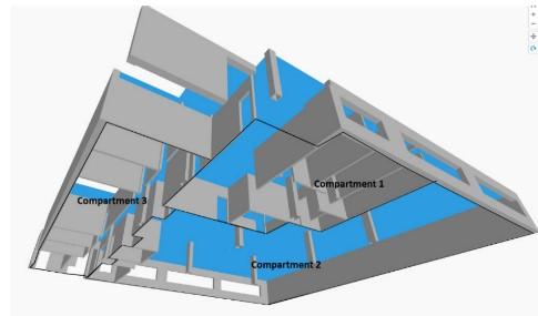
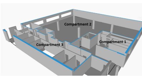
Finally, in Italy Amaro & Passalacqua in 2018 have implemented within the BIM model the calculation of the fire load. It was developed by introducing the characteristics of the materials and the calculation algorithm into Autodesk Revit software. This procedure in modeling software, although useful to identify the fire load due to furniture or cladding, is limited because it cannot take into account the fire load coming from storage materials that for certain activities have a relevant weight in the calculation.
Obviously, systems like the mvdXML or those that use tools like Dynamo linked to proprietary software are not suitable for a building permit verification. In the first case because
22 The path of travel tool in Revit lets you select 2 points in a floorplan and calculate the shortest route between those 2 points, avoiding elements you have defined as obstacles. The calculated path uses a 300mm clearance allowance to keep the center of the path from passing too close to an obstacle. The path of travel tool is not able to calculate vertical distances, i.e., it does not work on stairs. There are 3 primary calculations Revit makes, let’s review:
Travel Distance Limit: the distance to the nearest exit;
Dead-End Limit: the distance of a corridor with no end exit;
Common Path Limit: the portion of exit access that must be traversed before two separate and distinct paths are available).
(https://blogs.autodesk.com/revit/2020/02/18/revits-path-of-travel-tool-makes-for-quick-and-easy-egress/)
Automated Code Compliance Checking in fire prevention 51
Figure 33 | Dynamo script for the continuity of fire separations (source: Kincelova et al., 2020)
manipulations would be far too easy (Pfuhl, 2018), in the second also because the tools used are linked to proprietary software and therefore, they are useful only for professionals using that software. However, the reviews that have been presented want to help in identifying digital procedures that could be implemented within software purely related to code checking in the fire prevention field to promote a method of code checking objects oriented. In this way, if up to now in the field of fire prevention the official must verify the truthfulness of graphic works or technical reports. With the new methodology, having implemented in a single model the graphic and descriptive part, the official will receive a single file exported in an open format (IFC).
2.4.3. BUILDING MODEL PREPARATION
The second major part of rule checking is the building model preparation. To achieve this step, modelling software must support the IFC open data IFC to allow the export of models.
The preparation of the model may present two problems, one deontological and the other experimental. The first is connected to the specificity of the IFC standard, the second is linked to the quality of the tools used to export a model in IFC format, which may not be able to fully translate the data.
Regarding the first issue, so far, several studies in the fire prevention field have been done to identify which objects and properties of the IFC schema are useful to map the information required for fire design into a digital model. The research shows that the best method to deal with the deontological issue is to carefully analyse the fire prevention design process, then proposes the drafting of an IDM that highlights the required parameters and identifies which are the entities and IFC properties that best match them through the drafting of an MVD, and in case a match is not found introduce new ones. The last one in chronological order is the one undertaken by BuildingSMART International in 2020, described in §2.3.1 On the one hand, the proposal of drafting the Model view definition (MVD) for fire safety suggested by Max (KIT), Karlshoj (DTU), and Bekboliev (buildingSMART Germany) will allow to identify what are the information to be mapped for the prescriptive code checking, on the other hand, the proposed drafting of the two MVD, one for Fire Safety Engineering (FSE) and the other for Occupant Movement Analysis (OMA), will allow to cover also the checking of projects carried out according to the performance-based method
The second problem is related to the software developers who must respect what the IFC schema requires. In this regard, by analysing the two software used in this thesis (Autodesk Revit 2021 and Graphisoft Archicad 24) it has been highlighted that attributes that are related to one or more building model elements required for the check can belong to one of the following cases (Kincelova et al., 2020). A parameter could be automatic in modelling software, which means the information is filled in by the program when the element is drawn (e.g., wall geometry). Whereas a Built-in parameter is part of the modelling software, but its value is not automatically set; it is possible that in an existing project, the parameter is empty (e.g., fire-resistance rating). Finally, the modeler may be forced to create a new shared parameter because the attribute is absent, and neither are included in the IFC schema or in the modelling software; or he can deduce information from the
Digital standardization & Code Checking in fire prevention 52
information already present in the building model if it is properly manipulated. This will be the selected solution if adding a parameter representation of the info is not adapted.
Furthermore, a basic distinction must be made about how the values of the parameters should be provided. There are two types of data: those whose values are filled in manually because they are provided by the manufacturer such as the reaction to fire and those which must be calculated by the designer such as the length of the escape routes. In the second case, it is necessary to define a systematic digital procedure so that the data entered is calculated automatically and modified if the design changes (Figure 34).
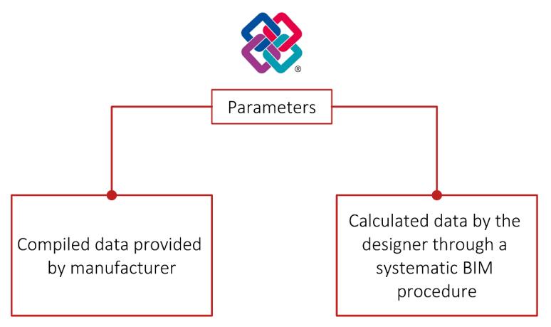
Below there is a brief description of the research conducted by on the modelling of macroscopic building evacuation using IFC data. The paper focuses on the differences and relationship between IFC and the macroscopic network model for evacuation (MNME), The spatial geometric model of an MNME includes two geometric objects: nodes, which represent rooms in a building, and arcs which represent the connecting paths of each room in the building (Figure 35) The geometric information of the room includes the area of the room and the coordinates of the centre point where those arcs include the length of the path. Based on the nodes and arcs, the model also requires corresponding attribute information to assist simulation analysis. As shown in Figure 35 there are three categories of attributes: node- and arc-related attributes, crowd-related attributes, and environment-related attributes. This study investigated methods to extract nodes, arcs, and the characteristic attributes attached to them, through building entities and relationships of IFC. The nodes of the MNME are formed by mapping the spaces in IFC (IfcSpace). To obtain the position of the IfcSpace is important to use the relationship IFCRelAggregates which connects spaces with the building storey where they are (Figure 36) Whereas to create an arc they used another concept of IFC that is the spatial connectivity. Therefore, based on the spatial boundary relationship
IfcRelSpaceBoundary of the IFC, shared building elements between two spaces can be used to map spatial adjacency. In addition to the connectivity between rooms, the MNME arcs also include the connectivity between different floors. Zhu et al This use the IfcRelContainedInSpatialStructure entity to search for instances of IfcStair in associated to the stories.
Automated Code Compliance Checking in fire prevention 53
Figure 34 | Types of parameters: compiled and calculated
Finally, to define the compartments in an IFC model BuildingSMART proposes two procedures shown in Figure 37. The first involves using an entity still little used in BIM because not implemented in the modelling software and yet to be fully defined by the developers of the standard
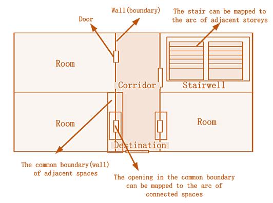
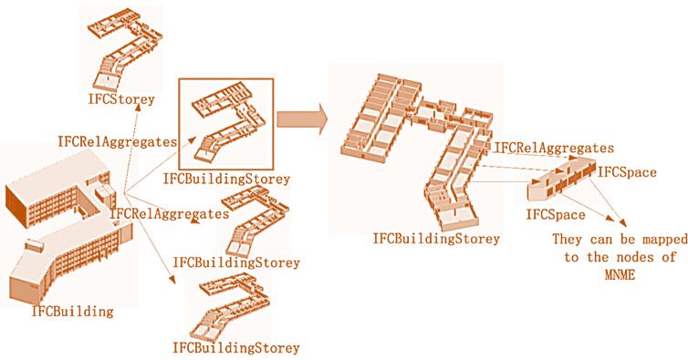
23 The second table shows some attributes that the authors founded investigating software of (MNME)
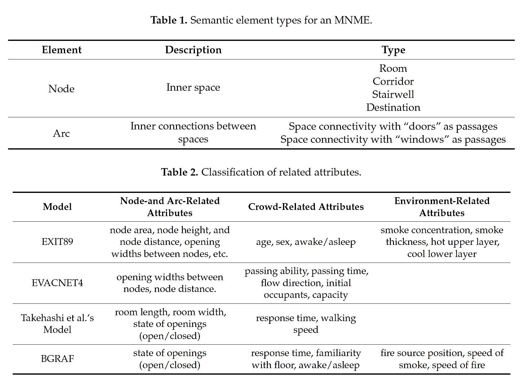
Digital standardization & Code Checking in fire prevention 54
Figure 35 | Elements and attributes for an MNME (source: Zhu et al., 2018)23
Figure 36 | Hierarchy relationships for the architectural spaces of IFC and connectivity mapping (Source: Zhu et al., 2018)
and introduced in the IFC4 schema. This class is IfcSpatialZone which is a non-hierarchical and potentially overlapping decomposition of the project under some functional consideration. A spatial zone might have its independent placement and shape representation. Physical elements that are referenced by this spatial zone are related using the IfcRelReferencedInSpatialStructure relationship as it is a non-hierarchical assignment in addition to the hierarchical spatial containment within a subtype of IfcSpatialStructureElement. Also, spaces, that are referenced by this spatial zone are related using the IfcRelReferencedInSpatialStructure relationship. The IfcSpatialZone itself can also be referenced by another spatial element using IfcRelReferencedInSpatialStructure. The IfcSpatialZone class has an enumerative attribute in which the Spatial Zone types are listed. BuildingSMART allows us to use this class also to define FireSafety Zones, so in a nutshell to define compartments. At the same time also the entity IfcZone can define fire compartmentation. In this case, it defines the geometric information about the fire compartment through the contained spaces. The spaces are related with a zone through the relationship IfcRelAssignsToGroup.
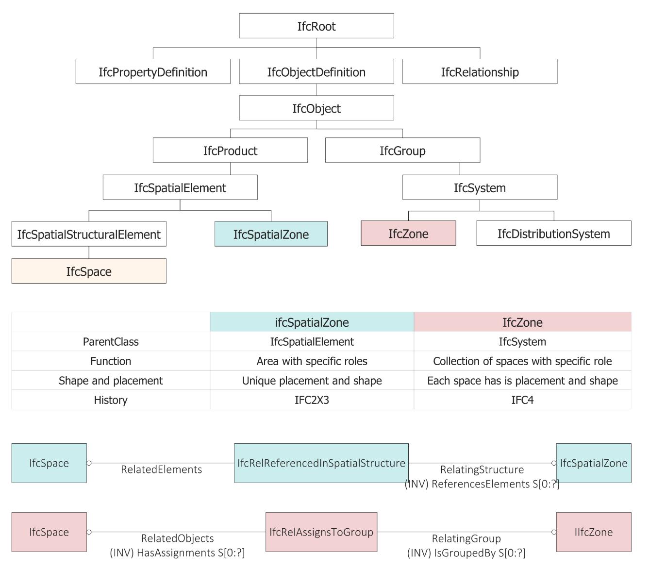
Automated Code Compliance Checking in fire prevention 55
Figure 37 | IfcZone and IfcSpatialZone comparison
In case of a zone denoting a (fire) compartment, the following types should be used, if applicable, as values of the ObjectType attribute: FireCompartment (a zone of spaces, collected to represent a single fire compartment), ElevatorShaft (a collection of spaces within an elevator, potentially going through many storeys), RisingDuct (a collection of vertical airspaces), RunningDuct (a collection of horizontal airspaces).
To date among the Property Sets that have relevance in the field of fire safety, and that IfcZone and IfcSpatialZone share there are: Pset_SpaceFireSafetyRequirements and Pset_SpaceOccupancyRequirements However, unlike the Pset_ZoneCommon which contains information such as the gross area of the zone or whether the zone is accessible to the public or handicapped persons, the Pset_SpatialZoneCommon does not allow this.
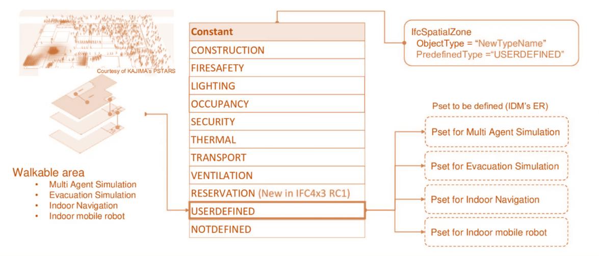
There is ongoing work by IFC focused on improving the definition of this class since it has great potential (Genova & Adachi, 2020). The idea that BuildingSMART researchers are pursuing is that it can also be used to define the Walkable area allowing to use of this class also for exodus simulations. All this, however, must be accompanied by Property Sets created ad hoc for each type of SpatialZone (Figure 38).
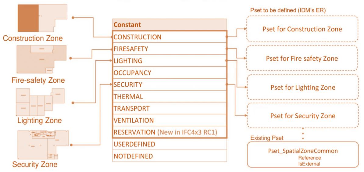
Digital standardization & Code Checking in fire prevention 56
Figure 38 | Future Use Case Type and properties of IfcSpatialZone
4. DEVELOPMENT OF AN IFC DATA MODEL FOR FIRE PREVENTION CHECKING
4.1. METHOD FORMALIZATION
Figure 42 analyses the methodological flow used. Since the code checking approaches must take into consideration the particularity of each domain, an analysis of the Italian Fire Prevention Code has been carried out. Since one of the challenges of code checking is to translate the rules in a machine-readable way, after a selection of some rules, a classification of them has been done and a semantic extraction of Object(s) in the information structure and of parameters has been done to find, where possible, the corresponding entities, attributes, and properties in the IFC data schema. For this purpose, a careful analysis of the IFC4.1 data schema has been conducted. We decided to analyse this version of IFC due to the fact that it is the latest official version, but a direct comparison with IFC4.2 and IFC4.3 was made in order to check for possible deprecations or additions of classes and parameters. When it was not possible to identify properties or attributes able to translate the parameters of the rules, proposals were made for the implementation of the schema, defining userdefined Property Sets, if the information content to be mapped was intrinsically Italian. These expansions of the standard are readable by everyone with tools for reading an IFC file, but they are modifiable only by the owners of those properties. In the case where the information required by the Italian regulations has been inherited from the European or international regulatory context, we have made proposals for revision of the IFC standard that would allow the use of IFC also in the field of fire prevention. At this point, we proceeded to verify that the information structure translated with IFC was mappable in a model through modelling software and to draw up a draft Information Delivery Manual.
4.2. ANALYSIS, MAPPING OF INFORMATION REQUIREMENTS AND BUILDING MODEL PREPARATION
To identify the requirements that must be considered to proceed to Code checking in the field of fire safety, in the following chapters the fire safety strategies reported in section S of the Fire Prevention Code were analysed. Since this thesis has focused mainly on the translation of the requirements for the fire safety strategies of reaction and resistance to fire, compartmentalization, and evacuation, the sections S.1, S.2, S.3, S.4 of Fire Prevention Code were examined. Besides, section G was also analysed as, by providing a set of general definitions, it helped study the various strategies.
4.2.1. CLASSIFICATION & EXTRACTION METHOD
First, some of the necessary concepts and attributes that are of regulation’s concern must be extracted. As fire safety regulations are often formulated implicitly, the terminology use can be inconsistent, and the information is very specific and concerns detailed matters, a classification has been done. The model of table that is used for the data extraction is shown in Table 4 (Appendix 1)
67
Reference Article
Clause number Clause text
Definition, Prescriptive rule, performance base rules
Table 4 | Proposed table for extraction of semantic
Object(s) in the information structure
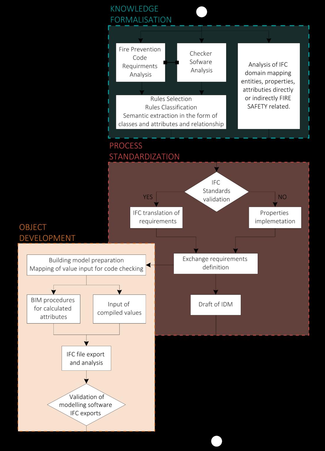
Define objects to which the rules is applied
Extract concepts and attributes contained in the clause text
Highlight relations with other clauses
Development of an IFC data model for Fire Prevention Checking 68
Classification
Parameter Relations
Figure 42 | General overview of the method
4.2.2. GENERAL DATA
The general data required for the delivery of a technical report to obtain Fire Prevention Certificate (Certificato di Prevenzione Incendi - CPI) include the address of the activity and the type of intervention. Types of intervention include new establishment, change of existing facilities or structures, existing expansion of more than 50%, existing adaptation, complete renovation, change of use, adjustment existing, non-substantial modifications. These first two pieces of information are mappable in an IFC model respectively by filling in the BuildingAddress attribute of the IfcBuilding (Figure 43) and the ObjectType attribute which instead is an attribute that the IfcProject class inherits from the IfcContext class (Figure 65). In order to identify the type of intervention, the choice fell on the ObjectType attribute because subtypes of IfcContext, as IfcProject, do not introduce a PredefinedType attribute that identifies the nature of the project. In the first case, the BuildingAddress attribute is not a text parameter and needs to be further specialised by another entity which is IfcPostaAddress (Figure 43).
IfcContext Attribute Type Description
5 ObjectType IfcLabel The object type denotes a particular type that indicates the object further. The use has to be established at the level of instantiable subtypes.
NOTE Subtypes of IfcContext do not introduce a PredefinedType attribute, therefore the usage of ObjectType is not bound to the selection of USERDEFINED within the PredefinedType enumaration.
#71=IFCPROJECT('344O7vICcwH8qAEnwJDjSU',#13,'Project',$,'NewEstablishment',$,$,(#67),#54);
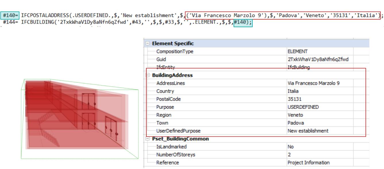
Analysis, mapping of Information Requirements and Building Model Preparation 69
Figure 43 | Visualization in BIM vision of exported IfcPostalAddress attributes
Figure 44 | IfcProject in STEP file
4.2.3. SUBJECT ACTIVITY IDENTIFICATION

According to the Italian regulation, the building is considered as a collector of functions that are grouped areas of the building which constitute the activities. Figure 45 shows how the concept of activity relates to that of the building. A building may contain several subject activities which in turn may contain one or more compartments (§0) but also non-compartmentalised spaces. But in the same way, an activity may be carried out in several buildings. In general, however, for each project, there will be a principal activity and secondary activities according to what is the predominant function fulfilled within the building.
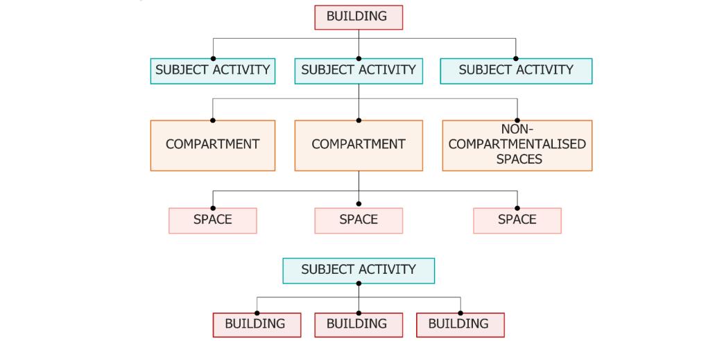
The methodology described in § 3.2 highlights how the definition of the activities within the building and the check of applicability of the activities subject to fire prevention controls is a fundamental aspect for identifying fire prevention measures. Each activity is subdivided into the relevant subclasses and risk categories (cat. A, B, and C) assigned based on the severity of the risk rather than the size or, in any case, the degree of complexity of the activity itself. Besides, for each activity, a brief description is provided, including the sub-class and the associated risk category. Figure 46 describes the identifier formed by the three codes.
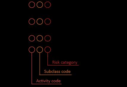
Development of an IFC data model for Fire Prevention Checking 70
Figure 45 | Relationships among activities, buildings, compartments, and spaces
Figure 46 | Example of Activity classification according to the Presidential Decree 151/2011
A comparison with Danish and Bavarian legislation is given below (Fire National Regulations 2020, 2020). In Denmark, the BuildingRegulations contains the rules for the construction of buildings, both private and commercial. Chapter 5 of this regulation, called “Fire Safety” states that «on determination of the necessary fire protection required to comply with the requirements of fire safety, a building must be divided into one or more building section with comparable fire risks. All building sections must be referred to a category of use». The regulation goes on to state that «The category of use must be determined based on whether a building section includes sleeping facilities, whether persons in the building section have been informed of escape routes and if they are able to bring themselves into safety and based on the maximum number of persons which can be accommodated in each room». With the Building Regulation 2018, risk classes are introduced. The risk class of a building section must be determined based on the use of the building, the complexity of the evacuation procedures for people with due consideration of the layout of the building and based on the fire load of the relevant building section. According to the Building Regulations 2018 if a building has several building sections which are classified into different risk classes, and the building sections share escape routes, the highest risk classification of one of the building sections must apply to all the building sections allocated to the escape routes. Another example is the Bavarian Building Regulations (BayBO) that provides a classification of the building. The classification affects the requirements of fire protection. Additionally, the Germany building fire regulations says that building can be grouped into standard buildings, non-regulated special constructions, and special constructions that are facilities and rooms of a particular nature or use, like high-rise buildings, shops, hotels, and hospitals.
The above shows that the starting point for the definition of fire prevention measures differs from Country to Country. In Italy, the classification is based on the functions that the building, or parts of it, contains. The Danish regulations instead classify building sections according to the type of occupants, their knowledge of the building, and the geometry of the building. The Bavarian regulation provides a classification based on the geometry of the building. Furthermore, while the Danish and Italian standards subdivide the building into zones, the Bavarian standard gives a generic class to the whole building.
Based on what has been described, it seems intuitive to define in the IFC data scheme una procedure for identifying activities but remembering that a building can contain one type of subject activity (or a single section as in the case of the Danish regulation) or several functions (or is divided into several sections in the case of the Danish regulation). The analysis of the IFC data model identified three possible methods for mapping the subject activity(ies) present in a building.
First procedure: IfcBuilding and its decomposition
The first procedure is to use the IfcBuilding entity, and the Spatial Aggregation Hierarchy proposed by IFC standard. All classes with spatial semantics inherit attributes and properties from the class IfcSpatialStructureElement might be used to define a spatial structure. The order of spatial structure elements being included in the concept for building projects are from high to low level: IfcProject, IfcSite, IfcBuilding, IfcBuildingStorey,and IfcSpace. The link among the spatial
Analysis, mapping of Information Requirements and Building Model Preparation 71
elements is provided through the relationship IfcRelAggregates as shown in Figure 47. The aggregation relationship IfcRelAggregates is a special type of the general composition/decomposition relationship IfcRelDecomposes and it can be applied to all subtypes of IfcObjectDefinition. This procedure involves using the concept templates Spatial Composition and Spatial Decomposition. Figure 48 shows the use of them to establish a spatial structure including site, building, building section and storey, space. At the top of the hierarchy there is the IfcProject object that describes the context within which the information about the project as a whole is represented. Important in this context is the use of the attribute CompositionType on the aggregated IfcSpatialStructureElement which is enumeration data type used to define whether the element is a complex, a part of a whole (PARTIAL) or simply an embedded element (ELEMENT) (Borrmann et al., 2018). For example, an IfcBuilding entity could be a building but could be also a complex of buildings or a building section. If an IfcBuilding instance has the attribute CompositionType set as ELEMENT, by using the inverse attribute IfcBuilding.Decomposes, it may be linked with other IfcBuilding instances that have the attribute CompositionType set as PARTIAL. At the same time, the IfcBuilding instances having the attribute CompositionType set as PARTIAL, are linked with the IfcBuilding instances, that has the attribute CompositionType set as ELEMENT, by using the inverse attribute IfcBuilding.IsDecomposedBy.
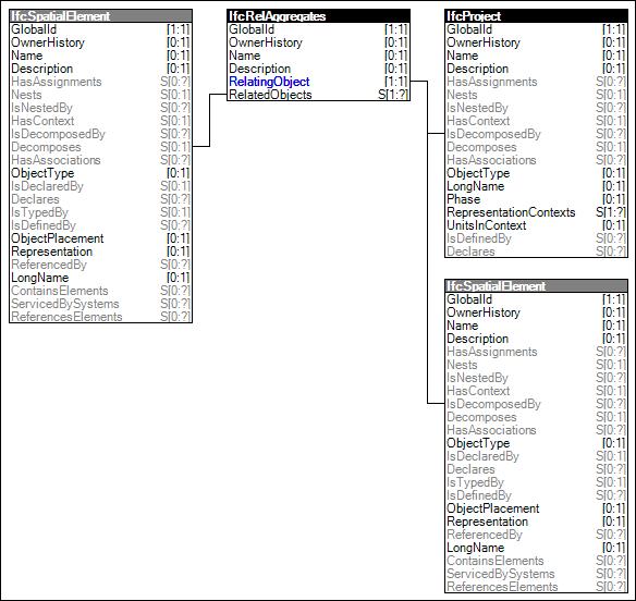
Development of an IFC data model for Fire Prevention Checking 72
Figure 47 | Spatial Composition concept template
The use of the concept templates Spatial Composition and Spatial Decomposition to define the activities in a building is limiting since, at least in the Italian scenario, its use would debase the IFC ontology. The question that needs to be asked is whether the decomposition of a building can respond to the definition of activities. The decomposition of a building can be useful when, for example, a single building is composed of communicating factory blocks. Decomposing a building into several buildings to represent several activities is not very meaningful because activities could be carried out, for example, in a single space or on a single floor, and therefore in the spatial structure of IFC it would correspond to an IfcSpace or an IfcBuildingStorey.
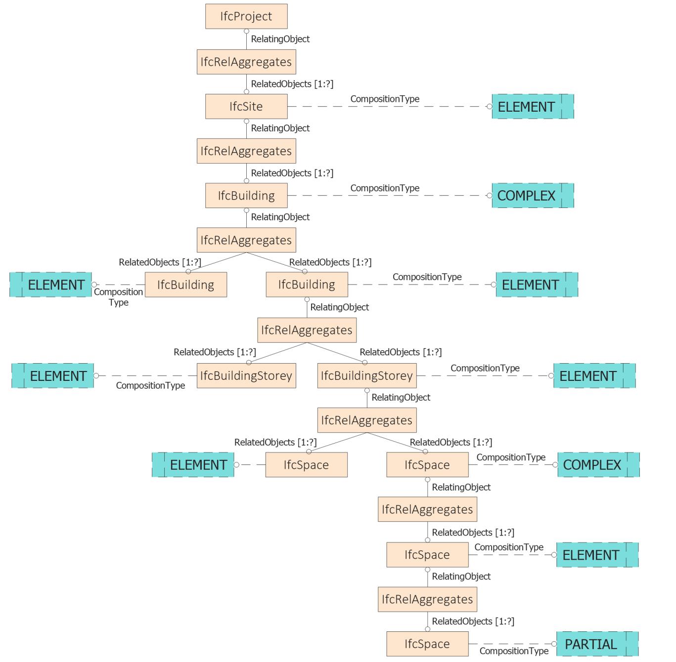
Analysis, mapping of Information Requirements and Building Model Preparation 73
Figure 48 | Entity inheritance of IfcSpatialStructureElement
Although this procedure is not considered a feasible way to map an activity, we describe it because in the Property Set Pset_BuildingCommon of the homonymous class there is the property FireProtectionClass (Table 5). This property was introduced by IFC4 and replaced the MainFireUse property of the previous version of IFC 2x3. Comparing the properties of the two versions of IFC, it is believed that the property of the previous version was more correct from a semantic point of view than the one with which it has been replaced. What emerges is that the FireProtectionClass property associates a protection class to the building, a procedure which in the Italian regulations is later by defining the performance levels. Whereas the Italian fire prevention procedure defines the class of activities carried out in a building based on the functions carried out, the severity of the risk, the size or number of occupants
Pset_BuildingCommon PSET_TYPEDRIVENOVERRIDE / IfcBuilding
Second procedure: IfcSpace and its decomposition
Since the first procedure is not significant to represent the Italian context, we proceeded to analyse another subtype of IfcSpatialStructure which is IfcSpace. Following the same logical reasoning as before: IfcSpace entity could be a space but could also be a complex of spaces or part of a space (Figure 48). This feature allows this entity to be used both to identify the spaces in a building and one or more complex IfcSpace to represent the various subject activities contained. Since the activities are carried out in spaces, it seemed correct to reason in terms of aggregation of spaces. Again, we must be careful not to devalue the meaning of the IfcSpace class and understand to what extent an IfcSpace entity set as COMPLEX through the CompositionType attribute can be a space in a building. In this case the simplest examples of a single activity being processed within a building or activities being processed on different floors of the building make this procedure ontologically unsound because the standard would then recommend using the IfcBuilding or IfcBuildingStorey classes.
Third procedure: IfcZone and Group Assignment
Finally, the last procedure, is so far considered the most correct, is described. It contemplates the idea of Zones.
A zone is a group of spaces, partial spaces or other zones. Zone structures may not be
Development of an IFC data model for Fire Prevention Checking 74
Table 5 | Pset_BuildingCommon Property Set (only fire safety properties shown)
Name Property Type Data Type Definition Ifc Release FireProtectionClass IfcPropertySingleValue IfcLabel Main fire protection class for the building which is assigned from the fire protection classification table as given by the relevant national building code. IFC4.1 MainFireUse IfcPropertySingleValue IfcLabel Main fire use for the building which is assigned from the fire use classification table as given by the relevant national building code. IFC2x3
hierarchical(incontrarytothespatialstructureofaproject -seeIfcSpatialStructureElement), i.e. one individual IfcSpace may be associated with zero, one, or several IfcZone's. IfcSpace's are grouped into an IfcZone by using the objectified relationship IfcRelAssignsToGroup as specified at the supertype IfcGroup. NOTE: Only objects of type IfcSpace, IfcZone and IfcSpatialZone are allowed as RelatedObjects. (BuildingSMART International, 2020b)
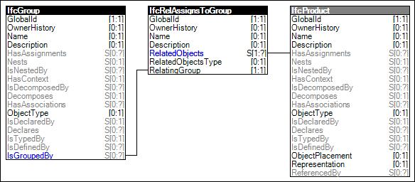
A zone can be identified as a collection of areas that have the same rule, but it does not provide geometrical representation attributes. It is merely a grouping of spaces, spatial zones (§2.4.3) or other zone. Therefore, it cannot be used for spatial zones having a different shape and size compared to the shape and size of aggregated spaces. The IfcZone class30 is a subtype of IfcSystem and inherits the Group Assignment concept template from the IfcSystem supertype: IfcGroup (Figure 49).
The use of this entity seems to be the most significant for mapping the Italian concept of subject activity as an activity takes its geometry from the spaces or compartments it contains and has spaces within separate buildings allow to group them together. Figure 50 shows an example whereby applying the concept of nesting zones within zones it is possible to define activities (in the example "School" and "Parking") and other zones within the activity.
The problem with this procedure concerns the identification of the activity category. Pset_SpaceFireSafetyRequirements had the property MainFireUse, the same property already presents in the first procedure, but which has been deprecated with IFC4
30 BuildingSMART International is keen to emphasise that IfcZone is considered as a spatial system (compared to the other types of systems: building services system, electrical system or analytical system), the name remains IfcZone for reasons of compatibility, rather than using an appropriate naming convention, such as IfcSpatialSystem.
Analysis, mapping of Information Requirements and Building Model Preparation 75
Figure 49 | Group Assignment concept template
MainFireUse IfcPropertySingleValue IfcLabel Main fire use for the space which is assigned from the fire use classification table as given by the relevant national building code.
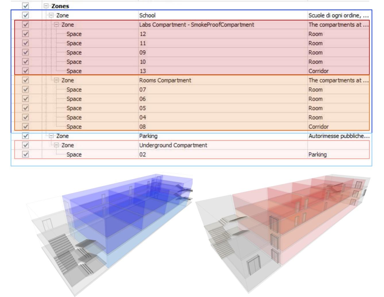
This class inherits the attributes Name and Description from the most abstract and root class, IfcRoot, while from the class IfcObject it inherits the attribute ObjectType. Faced with the possibility of using the same class for the FIreCompartment as proposed by buildingSMART and as we will see in §4.2.9, the ObjectType attribute is essential to define what kind of zone we are talking about: in this case a main or secondary subject activity. So, there are two possibilities:
Defining respectively the activity category, the activity name and the description with attributes Name, Long Name (attribute of IfcZone) and Description;
Development of an IFC data model for Fire Prevention Checking 76
Figure 50 | Visualization of IfcZone entities exported with Graphisoft Archicad 24
Name Property Type Data Type Definition
Table 6 | Pset_SpaceFireSafetyRequirements
Assigning to the entity IfcZone a classification.
Given that, as shown in Figure 46, each activity is identified by a code that defines the class and the sub-class of the activity, the second method is considered more correct. Figure 51 shows an example. The classification in IFC is not an attribute and it does not belong to specific Property Sets but it is a more organized system that must guarantee the use of multiple classifications within the same model. The IfcRelAssociatesClassification class assigns to an object (in this case IfcZone) a class that contains the classification reference in terms of code (with the Identification attribute) possibly separated by symbols (with the ReferenceTokens attribute) and title associated with it (with the Name attribute). With the Description attribute, it is also possible to provide a brief description of the classification and could be used to report the description provided by Presidential Decree 151/2011 for each activity (Figure 51). The IfcClassificationReference class assigns a classification to the object while the IfcClassfication class identifies which classification is being used. In this case, the one described in Presidential Decree 151/2011. Table 9 shows a summary of the attributes, with their respective values that group all the parameters used to map activities in an IFC model.
Table 7 | Attributes of IfcClassificationReference
1 Location IfcURIReference ? Location, where the external source (classification, document or library) can be accessed by electronic means. The electronic location is provided as an URI, and would normally be given as an URL location string.
2 Identification IfcIdentifier ? The Identification provides a unique identifier of the referenced item within the external source (classification, document or library).
3 Name IfcLabel ? Optional name to further specify the reference. It can provide a human readable identifier (which does not necessarily need to have a counterpart in the internal structure of the document).
S[0:?] Reference to all associations between this external reference and objects within the IfcResourceObjectSelect that are tagged by the external reference.
4
IfcClassificationReferen ceSelect ? The classification system or source that is referenced.
5 Description IfcText ? Description of the classification reference for informational purposes.
6 Sort IfcIdentifier ? Optional identifier to sort the set of classification references within the referenced source (either a classification facet of higher level, or the classification system itself).
The classification reference with which objects are associated.
The parent classification references to which this child classification reference applies. It can either be the final classification item leaf node, or an intermediate classification item.
Analysis, mapping of Information Requirements and Building Model Preparation 77
# Attribute Type Cardin ality Description
ExternalRefe renceForRes ources IfcExternalReferenceRe lationship @RelatingReference
ReferencedS ource
Classification RefForObject s
@RelatingClassification
IfcClassificationReferen ce @ReferencedSource S[0:?]
IfcRelAssociatesClassifi cation
S[0:?]
HasReferenc es
Table 8 |
# Attribute Type
Attributes of IfcClassification
Cardinality Description
1 Source IfcLabel ? Source (or publisher) for this classification.
NOTE that the source of the classification means the person or organization that was the original author or the person or organization currently acting as the publisher.
2 Edition IfcLabel ? The edition or version of the classification system from which the classification notation is derived.
NOTE the version labeling system is specific to the classification system.
3 EditionDate IfcDate ? The date on which the edition of the classification used became valid.
NOTE The indication of edition may be sufficient to identify the classification source uniquely but the edition date is provided as an optional attribute to enable more precise identification where required.
4 Name IfcLabel The name or label by which the classification used is normally known.
5 Description IfcText ? Additional description provided for the classification.
6 Location IfcURIReference ? Resource identifier or locator, provided as URI, URN or URL, of the classification.
7 ReferenceToke ns IfcIdentifier ? L[1:?] The delimiter tokens that are used to mark the boundaries of individual facets (substrings) in a classification reference. ClassificationF orObjects IfcRelAssociatesClassi fication
@RelatingClassificati on
HasReferences IfcClassificationRefer ence
@ReferencedSource
S[0:?] The classification with which objects are associated.
S[0:?] The classification references to which the classification applies. It can either be the final classification notation, or an intermediate classification item.
Development of an IFC data model for Fire Prevention Checking 78
Figure 51 | STEP file: representation of object classification in IFC
Entity
Mapped Concept
IfcZone; Object User Identity
IfcZone; Object Predefined Type
Attribute
Value
IfcZone.Name -> IfcLabel
General name of the activity like school, office, etc…
IfcZone.ObjectType -> IfcLabel
IfcRelAssociatesClassification.RelatedObj ects -> IfcDefinitionSelect
‘MainSubjectActivity ’ or ‘SecondarySubjectA ctivity’
IfcObjectDefinition
IfcRelAssociatesClassification.Name -> IfcLabel DPR 151/2011
IfcRelAssociatesClassification.RelatingCla ssification -> IfcClassificationSelect
IfcClassificationReference.Location -> IfcURIReference
IfcClassificationRefe rence o IfcClassfication
http://www.vigilfuo co.it/aspx/AttivitaS
oggetteElenco.aspx
IfcZone; IfcRelAssociatesCl assification; IfcClassificationR eference;
Classification Association
IfcClassificationReference.Name -> IfcLabel
IfcClassificationReference.Identification> IfcIdentifier
IfcClassificationReference.Description -> IfcLabel
IfcClassificationReference.ReferencedSo urce -> IfcClassificationReferenceSelect
Name of category
Code of category
Description of category
IfcClassification
IfcClassification.Source -> IfcLabel
‘Elenco delle attività soggette ai controlli dei Vigili del Fuoco ai sensi del D.P.R. 151/2011’
IfcClassification.Name -> IfcLabel D.P.R. 151/2011
IfcClassification.Location -> IfcURIReference
IfcZone.IsGroupBy -> IfcRelAssignsToGroup
IfcZone; IfcSpace; IfcRelAssignsToGr oup; Group Assignment
IfcRelAssignsToGroup.RelatedObjects -> IfcObjectDefinition
IfcRelAssignsToGroup.RelatingGroup -> IfcGroup
http://www.vigilfuo co.it/aspx/AttivitaSo
ggetteElenco.aspx
Analysis, mapping of Information Requirements and Building Model Preparation 79
Table 9 | Entities/ Attributes/ Concept Templates to map in a IFC Model the subject activities
The applications used to map the classes and attributes highlighted in this chapter have some gaps. Autodesk Revit 2021 does not have a concept of architectural/fire safety zones31 However, it is possible to export IfcZones using room shared parameters. By adding the shared text parameter "ZoneName" to the Revit "Rooms" category in the "IFC Parameters" parameter group, a user can specify the name of the zone that the room belongs to. Revit will then create one IfcZone for each unique "ZoneName" value and associate all the rooms with that value to it. In addition, the shared parameters "ZoneObjectType" and "ZoneDescription" can be used to set the object type and description of the IfcZone. A Revit room can be associated with up to 1000 zones by adding extra shared text paramaters. To add more zones to a room, add the shared parameters "ZoneName #", where # = 2,3,4, etc. In addition, the "ZoneObjectType" and "ZoneDescription" parameters can also be similarly extended to, e.g., "ZoneObjectType 2". A room will be associated with each zone that is defined for it. It is possible to export the properties of the Pset_ZoneCommon for a Zone as shown in Figure 52 containing an extract of the IFC shared parameter file32. But, since these parameters are associated to the spaces, if a space belongs to different zones, it is not yet possible to associate Property Sets (such as Pset_ZoneCommon) to all the IfcZones. Further property such as Pset_SpaceFireSafetyRequirements or Pset_SpaceOccupancyRequirements that according to IFC standard could be assign either to the class IfcSpace or to IfcZone, in Revit you can only associate them with spaces. A shortcut would be to use Revit Zones in the "Spaces and Zones panel" within Analyze Tab. This second way is not correct as the Zones introduced by the application are HVAC Zones. Graphisoft Archicad 24's exporter, on the other hand, does not show any problems in this respect. It allows zones to be defined by grouping the spaces and for each one it associates the actual property sets. About classification association, both the Graphisoft Archicad 24 and Autodesk Revit 2021 procedures are predefined by the software and do not allow missing attributes to be added to the exported classes (Figure 55). The only attribute among those shown in Table 9 that both applications do not allow to map is Description of IfcClassificationReference.
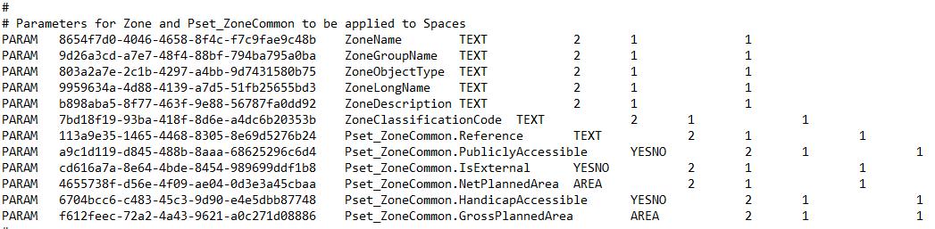
31 https://sourceforge.net/p/ifcexporter/wiki/Exporting%20Zones/
32 IFC Shared Parameters.txt contains the IFC parameters for manually updating an existing project with all or some of these parameters.
Development of an IFC data model for Fire Prevention Checking 80
Figure 52 | Revit IFC shared parameters file
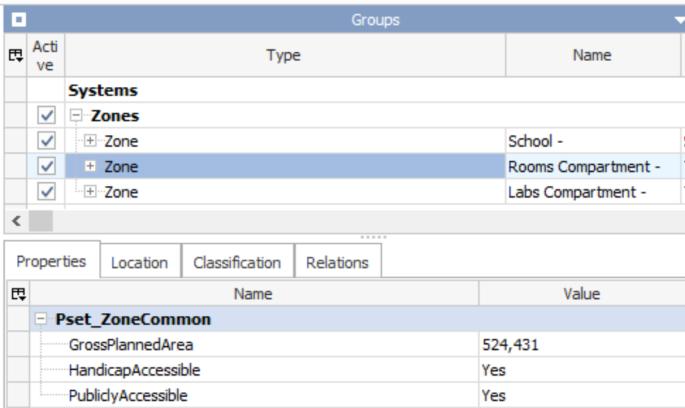
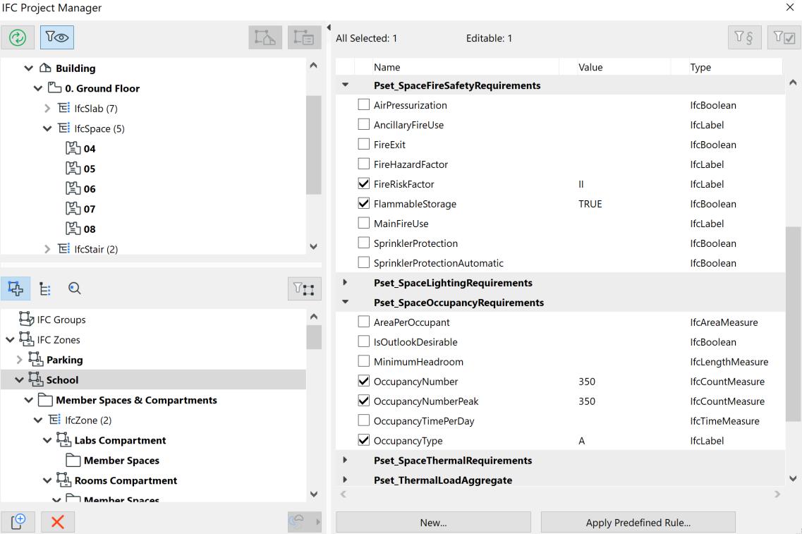
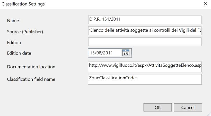
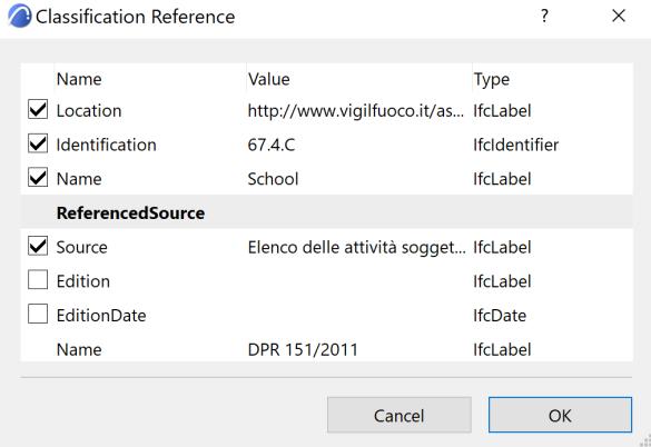
Analysis, mapping of Information Requirements and Building Model Preparation 81
Figure 53 | Example of IFC export of an IfcZone
Figure 54 | IFC translator of Graphisoft Archicad 24
Figure 55 | Autodesk Revit 2021 and Graphisoft Archicad 24 classification setting
4.2.4. ACTORS INVOLVED
The next issue to be addressed concerns the possibility of defining in a project the person in charge of the activity. The IFC standard proposes the class IfcActor among the classes of the Core data schemas:
The IfcActor defines all actors or human agents involved in a project during its full life cycle. It facilitatesthe use ofperson and organizationdefinitions inthe resource partof the IFCobject model. This includes name, address, telecommunication addresses, and roles. (BuildingSMART International, 2020b)
This entity enters into a logic of planning the activities associated with a building to be carried out during the whole life cycle of the building, from construction to disposal. The analysis of the fire prevention procedure described in chapter §3.2 has highlighted that the role of the manager is not merely administrative, in fact, according to Legislative Decree 626/94, risk analysis, including fire risk, is left to him, even if almost always he appoints a technician. Besides, he is the one who must send the Fire Authority "Certified segnalation of activity beginning" (SCIA - Segnalazione Certificata di Inizio Attività) and must certify the periodic renovation of fire safety compliance (defined in Annex 1 of Presidential Decree n.151/2011) by sending the authorities a declaration stating the absence of variations to the fire safety conditions together with the required documentation. Finally, chapter S.5 of the Code states that for a correct design of safety management, an exchange of information between the designer and the person responsible for the activity is necessary as indicated in Table
Activity Manager Designer
It provides the designer with information about fire hazards and all other input data about the activity necessary for fire risk assessment.
Receives information from the person responsible for the activity
They jointly evaluate fire prevention measures They assess the fire risk of the activity and define the fire strategy. Contributes to the safety management design. Defines and documents the safety management design. It implements the limitations and permissible modes of work for the appropriate management of the fire safety of the activity, to limit the probability of fire, ensure the proper functioning of safety systems and emergency management if a fire develops.
It provides the person in charge of the activity with the indications, instructions and permitted operating methods for the appropriate management of the fire safety of the activity, to limit the probability of fire, to ensure the correct functioning of the safety systems and the management of the emergency in the event of a fire developing.
For the reasons above, it is considered useful to be able to map in the model who is the activity manager. Three attributes are essential to proceed with this definition (Figure 55):
TheActor is an attribute of the IfcActor class that identifies who the person is. It links to the IfcPerson class, which not only provides the person's first and last name but also its role;
Development of an IFC data model for Fire Prevention Checking 82
10
Table 10 | Duties of the designer and manager of the activity in the field of safety management design
The Role attribute is an enumerative attribute of the IfcPerson entity. The enumeration defines roles that may be played by an actor. In the list of roles, however, none can identify the person responsible for the activity. In this case, the IFC standard provides the attribute UserDefindRole which allows for the specification of user defined roles beyond the enumeration values listed in the Role attribute of type IfcRoleEnum. When a value is provided for attribute UserDefinedRole in parallel the attribute Role shall have enumeration value USERDEFINED;
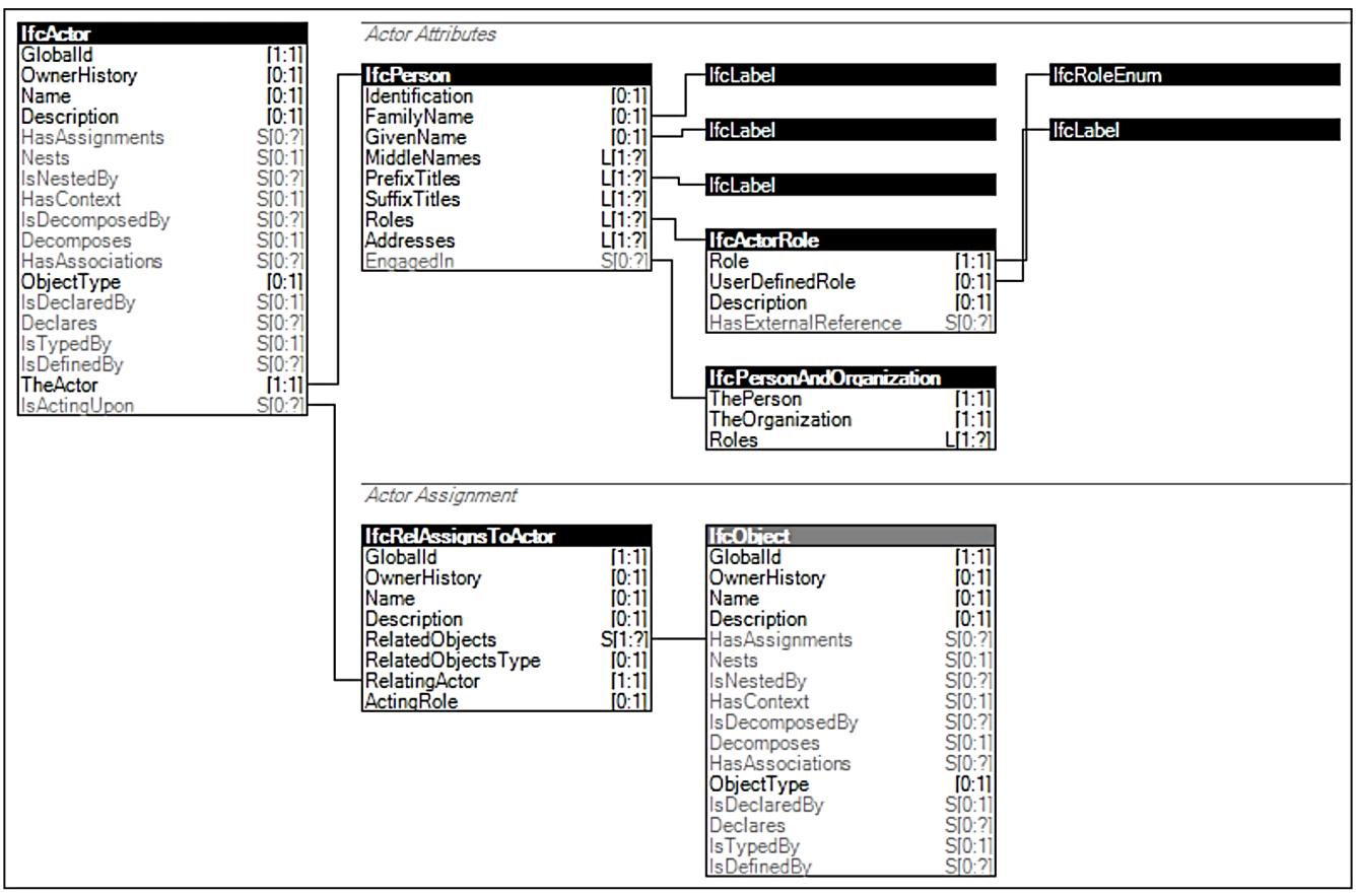
IsActingUpon is an inverse attribute of IfcActor which relates to the direct attribute of IfcRelAssignToActor. This class makes it possible to relate TheActor, i.e., the person responsible for the activity, to the IfcZone entity representing the activity itself.
The other essential figure in fire protection design is the fire protection designer who in an IFC logic should be the owner of the IFC file identified through the attribute OwnerHistory of the IfcProject.
4.2.5. FIRE RISK EVALUATION FOR THE ACTIVITY
The risk assessment of fire (Sabatino, 2014) is a process to detect the level of fire risk in a workplace and assess the actions and measures to minimize it due to the activities carried out on your premises or by some external influences. According to Legislative Decree 626/94, risk analysis, including fire risk, is left to the owner of the activity and almost always to a technician appointed by
Analysis, mapping of Information Requirements and Building Model Preparation 83
Figure 56 | Ifc Actor class and its concept templates
him. In Annex 1 of the Ministerial Decree of 10 March 1998, Fire Risk means the probability that the potential level of occurrence of a fire is reached and that the consequences of the fire on the people present will occur. The fire risk assessment takes into account several factors such as the type of activity, the materials stored and handled, the equipment present in the workplace, the construction characteristics of the workplace including cladding materials, the size and layout of the workplace, the number of people, and their readiness to leave in the event of an emergency. The approach to fire risk assessment consists of the following steps:
Identification of fire hazards (e.g., easily combustible and flammable substances, ignition sources and heat sources, situations that may result in the easy spread of fire);
Identification of workers and other persons in the workplace who are exposed to fire risks;
Identification of those exposed to fire risks;
Elimination or reduction of fire hazards. For each identified fire hazard, it is necessary to assess whether it can be: eliminated, reduced, replaced with safer alternatives, separated or protected from other parts of the workplace, bearing in mind the overall level of risk to people's lives and the requirements for the proper conduct of the activity;
Fire risk assessment;
Verification of the adequacy of existing safety measures or identification of preventive and protective measures necessary to eliminate or reduce residual fire risks.
The regulations set out three levels of possible risk (Table 11), which become fundamental for determining strategies for protective action.
One of the most important steps in assessing the fire risk in an activity, room or compartment is the calculation of the design fire load33. The specific fire load is determined using the equations given in Table 12.
The Fire Load calculation is commonly divided into two categories: movable contents and interior finish. The first one is the fire load of combustible furniture, equipment, goods, and supplies brought in for the use of the occupant. The secondo one is the fire load of exposed combustible materials permanently affixed to walls, ceilings, or floors plus doors, trim, and built-in fixtures.
Modern science studies fire, like other risks, by analysing available data and, above all, by using the concept of multidisciplinary, which is well suited to this type of event. Risk is defined as the combination of the factors "likelihood of occurrence" and "magnitude of consequences" because of exposure to hazards. To limit the fire risk it is necessary to act on the factors that determine it, both on the frequency and the consequences. It is possible to limit the frequency of fires through a series
33 Standardised at European level by the EN 1991-1-2: 2002 Actions on Structures - Part 1-2: General ActionsActions on Structures Exposed to Fire
Development of an IFC data model for Fire Prevention Checking 84
of measures in the field of prevention. On the other hand, limiting the consequences of fires is achieved using protection systems that are identified according to the type of consequences to be avoided.
Where:
Ir is the fire risk;
F the likelihood of occurrence;
M the magnitude of consequences.
Low
Workplaces or parts of workplaces in which low-flammability substances are present and in which the local and operating conditions offer little possibility of the development of fires and in which, in the event of fire, the likelihood of fire spreading is considered to be limited.
Average Workplaces or parts of workplaces in which flammable substances and/or local and/or operating conditions are present which may favour the development of fire but in which, in the event of fire, the probability of fire spread is considered to be limited.
High Workplaces or parts of workplaces in which highly flammable substances and/or local and/or operating conditions are present and in which there is a high probability of fire development and a high probability of flame spread in the initial phase, i.e. it is not possible to classify them as low or medium fire risk.
qf nominal value of the specific fire load [MJ m2];
gi mass of the the i-th combustible material [Kg];
Hi lower calorific power of the i-th combustible material [MJ Kg];
mi factor of participation in the combustion of the i-th combustible material;
ψi factor of limitation of the participation in the combustion of the i-th combustible material;
A gross compartment floor area or, in the case of localised fires, the effective gross floor area of the fire load distribution [m2]
fire load
qf,d specific design fire load [MJ m2];
δq1 factor that takes into account the fire risk in relation to the size of the compartment;
δq2 is the factor that takes into account the fire risk in relation to the type of activity undertaken in the compartment;
δn is the factor that takes into account the fire risk in relation to the type of activity undertaken in the compartment.
The state of the art methods for fire risk assessment can be grouped into three macrogroups (Ordine Ingegneri di Sondrio, n.d.):
Analysis, mapping of Information Requirements and Building Model Preparation 85
���� = ������
risk
Table 11 | Fire risk levels
Fire
level Risk Description
specific design fire load qf,d qf = ∑ gi n i=1 ×Hi×mi×Ψi A
Table 12 | Fire Load Calculation (source: Annex I Ministerial Decree 12 April 2019 - S.2.9)
nominal
qf,d=qf ×δq1 ×δq2 ×∏δn
value of the specific
Quantitative methods; Semi-quantitative methods; Qualitative methods.
The quantitative methods are based on mathematical estimation of the values of the probability of occurrence F of the fire event, and of the magnitude M of the expected damage. The use of such methods is limited to relevant risk factors, multiple and complex hazard sources, and conditions. The semi-quantitative methods are calculation models used when a more in-depth risk assessment is required, but without arriving at a rigorous quantitative estimate. They assign a conventional 'weighted' numerical value to the hazard and exposure parameters that contribute to the risk. Then, using mathematical relations, they provide risk indices, grouped in level classes. Software using these methods are based on the separate assessment of the potential fire risk (fire load and multiplier factors) and the available prevention and protection measures (compensation factors to account for the decrease in risk associated with compliance). The qualitative methods are based on the definition of conventional classes or levels of the values of the probability of occurrence F of the fire event, and the entity M of the expected damage, associated with conventional numerical values not referred to as measurable quantities. The fire risk rating is calculated using the risk matrix table, considering the combined results for likelihood and consequences.
From the above excursus, it is clear that the risk assessment process is a performance process that is difficult to standardise through parameters. The definition, therefore, will be the responsibility of the designer who then assigns the activity or areas of the activity a certain risk value based on the assessment carried out. The risk analysis could concern the whole activity, a compartment, or a specific risk area, it is evident that the value obtained from the analysis is attributable to areas of a building. At present, the IFC classes used to detect zones or spaces of a building (IfcSpace, IfcSpatialZone, IfcZone) are attributable to the Property Set Pset_SpaceFireSafetyRequirements (Table 13). The property FireRiskFactor, defining the fire risk of the space, can be filled in by the designer with the risk level (Table 11) obtained from the analysis he has carried out.
Name Type Description
FireRiskFactor P_SINGLEVALUE / IfcLabel
FlammableStorage P_SINGLEVALUE / IfcBoolean Indication whether the space is intended to serve as a storage of flammable material (which is regarded as such by the presiding building code. (TRUE) indicates yes, (FALSE) otherwise.
FireExit P_SINGLEVALUE / IfcBoolean Indication whether this object is designed to serve as an exit in the case of fire (TRUE) or not (FALSE). Here whether the space (in case of e.g., a corridor) is designed to serve as an exit space, e.g., for fire escape purposes.
Development of an IFC data model for Fire Prevention Checking 86
Table 13 | Properties of Pset_SpaceFireSafetyRequirements
Fire Risk factor assigned to the space according to local building regulations. It defines the fire risk of the space at several levels of fire hazard.
SprinklerProtection P_SINGLEVALUE / IfcBoolean Indication whether the space is sprinkler protected (TRUE) or not (FALSE).
SprinklerProtectionAutomatic P_SINGLEVALUE / IfcBoolean Indication whether the space has an automatic sprinkler protection (TRUE) or not (FALSE). It should only be given, if the property "SprinklerProtection" is set to TRUE.
AirPressurization
P_SINGLEVALUE / IfcBoolean Indication whether the space is required to have pressurized air (TRUE) or not (FALSE).
Similarly, fire load should also be a property that can be associated with spaces and zones in a building, but to date, the IFC standard does not have a parameter for this, even though the fire load calculation procedure is standardised at the European level. For this reason, the introduction of the property SpecificDesignFireLoad in the Pset_SpaceFireSafetyRequirements could be a solution (Figure 57). Properties associated with materials such as those highlighted in Table 14 would allow it to be calculated. However, the fire load calculability analysis shows that the definition of the fire load must be the precise responsibility of the designer who will assign the room or area a certain fire load and the process cannot be automated as it is not possible to expect everything that constitutes a fire load to be modelled within a design. The most significant example is that of a paper factory, the amount of paper inside, which makes up a large proportion of the fire load, is not modelled in a three-dimensional model. Therefore, the data entered in the threedimensional model will be a compiled data of the designer's responsibility.
Analysis, mapping of Information Requirements and Building Model Preparation 87
Name Type Description Pset_MaterialFuel CombustionTemperature P_SINGLEVALUE / IfcThermodynamicTemperatureMeasure Combustion temperature of the material when air is at 298 K and 100 kPa. CarbonContent P_SINGLEVALUE / IfcPositiveRatioMeasure The carbon content in the fuel.
is measured in weight of carbon per unit weight of fuel and is therefore unitless. LowerHeatingValue P_SINGLEVALUE / IfcHeatingValueMeasure Lower Heating Value is defined as the amount of energy released (MJ/kg) when a fuel is burned completely, and H2O is in vapor form in the combustion products. HigherHeatingValue P_SINGLEVALUE / IfcHeatingValueMeasure Higher Heating Value is defined as the amount of energy released (MJ/kg) when a fuel is burned completely, and H2O is in liquid form in the combustion products.
Table 14 | Property Sets of IfcMaterial
This
4.2.6. ASSIGNMENT OF RISK PROFILES
Following the steps of fire prevention methodology the next one is the attribution of the risk profiles to the activity and the compartments. They are simplified indicators for assessing the fire risk of an activity and are used to assign performance levels. The Code sets out three types of riskprofiles: Rlife risk profile concerning human life safety; Rprop risk profile concerning the protection of property and Renv: riskprofile concerning the protection of the environment. The Rlife riskprofile was introduced by the BS 9999: 200834, where it is generically called Risk Profile. According to the standard, the definition of Risk Profile for their building (or part of) is necessary to establish the minimum package of fire safety measures (i.e., travel distance, stair and exit widths, and level of fire alarm). This is the same procedure described in the Italian Fire Prevention Code The Rlife risk profile shall be assigned to each compartment of the activity, whereas the Rprop and Renv risk profile shall be assigned to the entire activity.
The Rlife risk profile is assigned by compartment in relation to the following factors:
δocc: prevailing characteristics of the occupants who shall be in the fire compartment (e.g, occupants are awake and familiar with the building, occupants are awake and not familiar with the building, occupants may be asleep …) (Annex I Ministerial Decree of 12 April 2019 – G.3.2.2);
δα: prevailing characteristics of the speed of the propagation of the fire referred to the time tα in seconds used by the thermal potential to reach 1000 Kw (Annex I Ministerial Decree of 12 April 2019 – G.3.2.2)
The Rlife riskprofile of the activity will be the worst of the Rlife riskprofile of the compartments that make up the activity. Whereas the Rlife risk profile of the escape route will be the worst of the compartments serviced by the route.
34 BS 9999 was published by the British Standards Institution in October 2008. It provides recommendations and guidance on the design, management, and use of buildings to achieve reasonable standards of fire safety for all people in and around buildings. Applicable to new buildings and to alterations, extensions, and changes of use of an existing building. Covers the entire life cycle of a building.
Development of an IFC data model for Fire Prevention Checking 88 Pset_MaterialCommon Name Type Description MolecularWeight P_SINGLEVALUE / IfcMolecularWeightMeasure Molecular weight of material (typically gas). Porosity P_SINGLEVALUE / IfcNormalisedRatioMeasure The void fraction of the total volume occupied by material (Vbr- Vnet)/Vbr. MassDensity P_SINGLEVALUE / IfcMassDensityMeasure Material mass density
The assessment of the Rprop risk profile is carried out according to the strategic nature of the entire activity or of the areas that are part of it, and according to the eventual historical, cultural, architectural, or artistic value of them or of the assets they contain (Table 15).
The designer assesses the Renv risk profile in the event of fire, distinguishing the areas of activity in which this risk profile is significant, from those where it is not significant. The assessment of the Renv risk profile shall consider the location of the activity, including the presence of sensitive receptors in outdoor areas, the type and quantities of combustible materials present, and combustion products developed by them in the event of fire, and the fire prevention and protection measures adopted.
Except for the Rlife risk profile, all other profiles are defined by Italian regulations and there is no property in IFC suitable to map them. Actually, there are two properties Pset_SpaceOccupancyRequirements.OccupancyType e Pset_BuildingCommon that are useful in the context of risk profiles. In the first case, the OccupancyType property would allow to associate to spaces, zones, or spatial zones the occupancy type defined according to the presiding national building code. In the second case, the IsLandmarked property would tell whether the building is listed as a historic building (TRUE), or not (FALSE), or unknown. However, there are no suitable properties to define the speed of the propagation of the fire or whether the building is strategic or not. Therefore, this is the case where it is necessary to expand the IFC standard with user-defined Property Sets to map properties that the international standard does not contemplate. For this reason, three properties have been introduced grouped under the user-defined Property Set, Pset_FireRiskProfiles, each for each risk profile and two other properties aimed at defining the fire spread rate (FireGrowthRate -> IfcLabel) and the strategic or non-strategic function of a building (IsBuildingStrategic -> IfcLogical). For these two properties, an extension of the standard should be proposed, representing general concepts that can be shared by all. The first one, FIreGrowthRate could be part of the Pset_SpaceFireSafetyRequirements being a property that can be defined for a space as well as for a zone. The second property could be a property of Pset_BuildingCommon as well as the IsLandmarked property. Figure 57 shows an example of an IFC export.
4.2.7. FIRE REACTION
Fire reaction is a passive fire protection measure effective in the first phase of fire propagation (pre-flashover), characterized by the evacuation of the occupants, and it has the purpose of limiting the ignition of materials and retarding the evolution of the fire. It expresses the behaviour of a combustible material which, through its decomposition, participates in the fire to which it has
Analysis, mapping of Information Requirements and Building Model Preparation 89
Restricted structure No Yes Strategic structure No Rprop = 1 Rprop = 2 Yes Rprop = 3 Rprop = 4
Table 15 | Assignment of Rprop (source: Annex I Ministerial Decree of 12 April 2019)
been subjected under specific conditions, increasing the temperature in the room, and increasing its speed of propagation.
The construction products shall be classified according to their fire reaction when their enduse condition is such that it contributes to the generation and spread of fire and smoke within the room of origin. European Standard EN 13501-1 provides the fire reaction classification procedure for all products and building elements.
The potential contribution of a product to a fire does not only depend on its intrinsic properties and the thermal attack but also considers its end use application and function. The end use application mainly includes the orientation of the product and the position in relation to other adjacent products (substrate, fixing etc.). The main properties that determine the class to which a specific product belongs are non-combustibility, ignitability, the spread of flames, calorific value, and the production of smoke and burning drops.
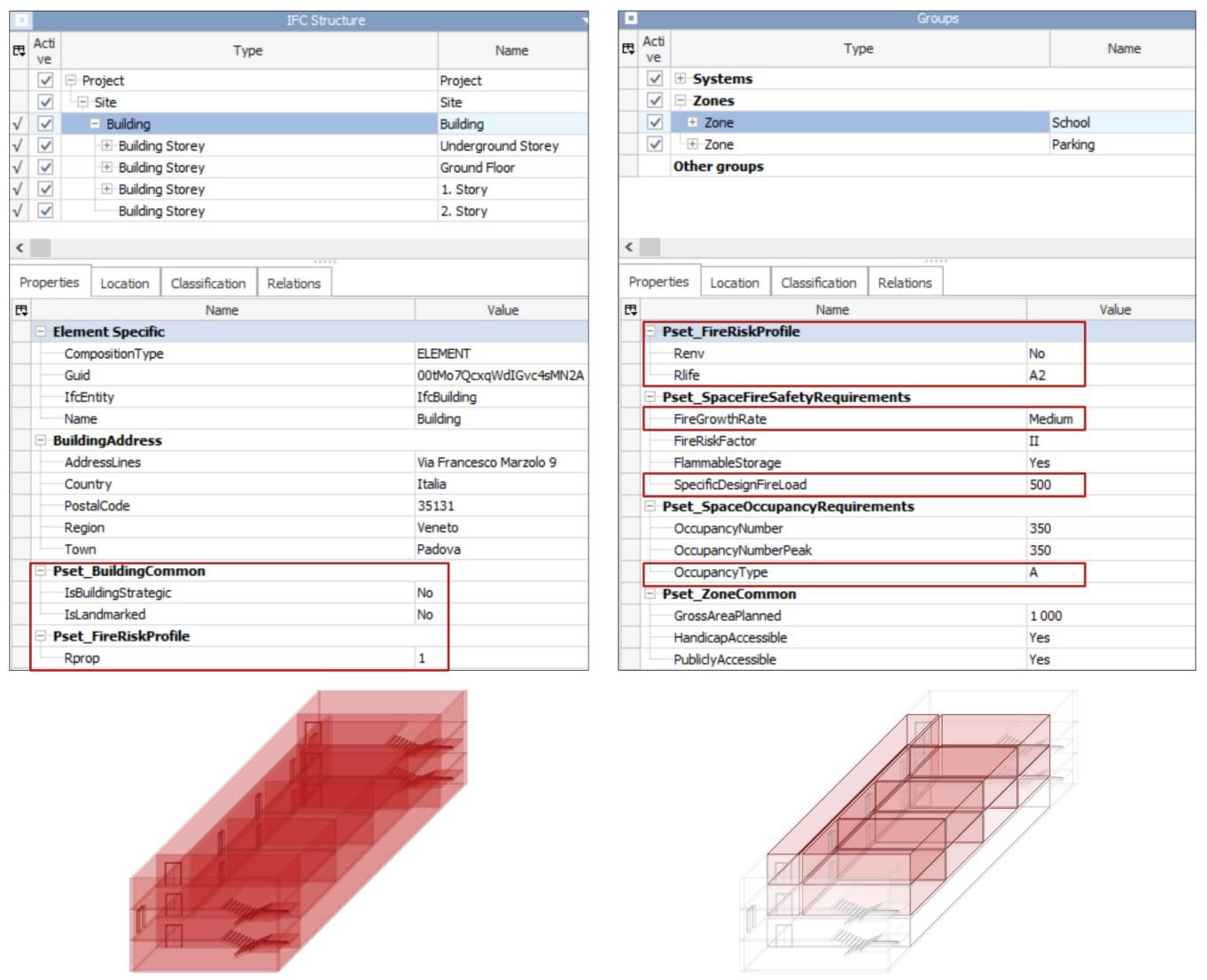
Development of an IFC data model for Fire Prevention Checking 90
Figure 57 | Visualization of Property Set of IfcBuilding and IfcZone exported with Graphisoft Archicad 24
The European legislation for the determination of the fire reaction class of construction products35 divides these into three main categories: construction products, excluding floorings, floorings, and construction products, excluding floorings
Construction products are classified into seven different Euroclasses A1, A2, B, C, D, E, F. Flooring materials are classified according to the same classes followed by the abbreviation “FL”. Flooring is the upper layer(s)of a floor, comprising any surface finish with or without an attached backing and with any accompanying underlay, interlayer, and adhesives (EN 13501-1). On the other hand, the Euroclass of materials used for pipe insulation has the sub-index "L". All the materials classified A2, B, C, D obtain an additional classification regarding the emission of smoke and the production of flaming droplets and/or particles. Smoke emission level values range from 1 (absent/weak) to 3 (high), whereas, flaming droplets and/or particles production value range from 0 (absent) to 2 (high). Class A1 is the highest requirement level that cannot be combined with subclasses for smoke (s) and burning droplets (d). Class E can either stand alone or be combined with d2. Class F has no requirement and cannot be combined with sub-classes. For flooring products is provided the additional classification “s” for smoke emission only and this could be combined just with A2fl, Bfl, Cfl, Dfl. The classes A1fl, Efl, Ffl cannot be combined with sub-classes.
On the other hand, in Italy materials are assigned to classes 0,1,2,3,4,5 as their participation in combustion increases36. Those in class 0 are non-combustible, those in class 5 are highly flammable combustible materials. The Ministerial Decree of 15 March 2005 integrated with the Ministerial Decree of 16 February 2009, contains tables in the annexes with which the Italian fire reaction classes can be "converted" into Euroclasses (Table 16). Therefore, in the Fire Prevention Code, the Italian reaction to fire classification has its European correspondent.
As stated in §3.2 the first step in the definition of the fire prevention measure is the specification of the performance level. The performance levels for the reaction to fire of materials used in activities are defined according to the fire contribution of the materials37. One of the most important changes in the 2019 update of the Code concerns the definition of performance levels for this fire prevention measure. They are to be applied to the settings (areas) of the activity where it is intended to limit the participation of materials in the combustion and reduce the spread of fire and
35 According to the European Standard EN 13501 a construction product could homogeneous or nonhomogeneous. A homogeneous product consists of a single material and has uniform density and composition at all levels; a non-homogeneous product instead consists of one or more substantial and/or non-substantial component. A substantial component is a material that is a significant element in the composition of a non-homogeneous product. A non-substantial component is a material that does not constitute a significant part of a non-homogeneous product. For a homogeneous product, it is easy to provide the reaction to fire because it is composed of a single material. If the product is non-homogeneous, the fire reaction class is determined indirectly by prescriptive rules, from the data obtained in their substantial and non-substantial components.
36 This classification can be found in Ministerial Decrees 26/06/1984 and 03/09/2001: “Classificazione di reazione al fuoco e omologazione dei materiali ai fini della prevenzione incendi”
37 For performance level I the assessment of the degree of participation of the material in the fire is not required and therefore the material can participate in a significant way in the fire without providing any passive protection.
Analysis, mapping of Information Requirements and Building Model Preparation 91
their assignment varies depending on whether is considering an escape route or other rooms of the activity and depends on the Rlife risk profile (Annex I Ministerial Decree 12 April 2019 - S.1.2-3)
For the final Code Checking, the Fire Prevention Code introduces groups of materials (GM) that are heterogenic in classification but similar in fire behaviour. There are five groups in total: GM0, GM1, GM2, GM3, and GM4. The GM0 group consists of all materials with class A1 reaction to fire in Europe and class 0 reaction to fire in Italy. Tables S.1-4 - S.1-7 of the Code show the class of fire reaction for the materials included in groups GM1, GM2, GM3, an example is given in Table 17. While GM4 includes all the materials not included in the other groups38. The deemed-to-satisfy solutions proposed in section S.1 require the use of materials belonging to the GM1, GM2, GM3 groups.
The most relevant changes introduced by the 2019 version of the Code are found in the category of cladding and finishing materials. The logic of the Code has moved towards the goal of defining the fire reaction classes of all the elements making up the design stratigraphy. For example, to prevent the spread of fire from the inside to the outside, the items "roofing materials, roofing panels, roofing sheets" have been added to the category of suspended ceilings (Table 17). For example, when you consider, a ceiling stratigraphy and you must guarantee a performance level III and therefore adopt GM2 materials, the overall stratigraphy of the ceiling must guarantee reaction to fire B-s2,d0, and not only the last exposed material. Another example is the Code's requirement to assess the reaction to fire of both the walking surface and the concealed surface of raised floors (Amaro, 2020b).
(A2-s1,d0), (A2-s2,d0), (A2-s1,d1), (B-s1,d0), (B-s2,d0), (Bs1,d1)
(A2-s1,d0), (A2-s2,d0), (B-s1,d0), (B-s2,d0)
(A2-s1,d0), (A2-s2,d0), (A2-s3,d0), (A2-s1,d1), (A2-s2,d1), (A2-s3,d1), (B-s1,d0), (B-s2,d0), (B-s1,d1), (B-s2,d1)
II 2 (A2-s1,d2), (A2-s2,d2), (A2-s3,d2), (B-s3,d0), (B-s3,d1), (B-s1,d2), (Bs2,d2), (Bs3,d2), (C-s1,d0), (C-s2,d0), (C-s1,d1), (C-s2,d1)
III 3 (C-s3,d0), (C-s3,d1), (C-s1,d2), (C-s2,d2), (C-s3,d2), (D-s1,d0), (Ds2,d0), (D-s1,d1),
38 The materials classified in Tables S.1-4 - S.1-7 are furniture materials, cladding and finishing materials, insulation, and installation materials.
Development of an IFC data model for Fire Prevention Checking 92
Italian classification Type of use European Classification 0 (non-combustible products) Flooring A1FL Wall A1 Ceiling A1 Linear A1L 1 (products installed along escape routes) Flooring (A2FL-s1),
FL-s1) Wall
Ceiling
Unclassified products Flooring FFL Wall F Ceiling F Linear FL Italian classification European Classification Wall use I 1
Table 16 | Tables of Ministerial Decree of 15 March 2005 integrated with the Ministerial Decree of 16 February 2009 for the conversion of Italian fire reaction classes from European fire reaction classes.
(B
Flooring use
(D-s2,d1)
I 1 (A2FL-s1), (A2 FL-s2), (B FL-s1), (B FL-s2)
II 2 ((CFL-s1), (CFL-s2)
III 3 ((DFL-s1), (DFL-s2)
Ceiling use
I 1 (A2-s1,d0), (A2-s2,d0), (A2-s3,d0), (A2-s1,d1), (A2-s2,d1), (A2-s3,d1), (B-s1,d0), (B-s2,d0)
II 2 (B-s3,d0), (B-s1,d1), (B-s2,d1), (B-s3,d1), (C-s1,d0), (C-s2,d0)
III 3 (C-s3,d0), (C-s1,d1), (C-s2,d1), (C-s3,d1), (D-s1,d0), (D-s2,d0)
Table
Materials description
Ceiling cladding [1]
False ceilings, roofing materials [2], roofing panels [2], roofing sheets [2]
Raised flooring (hidden surface)
Wall cladding [1]
Internal partitions, partition walls, suspended walls
Floor cladding [1]
Raised flooring (accessible surface)
1 B-s1,d0
1 Bfl-s1 1 Cfl-s1 2 Cfl-s2
[1] When treated with fireproof paint products, the latter must have the corresponding classification indicated and be suitable for the foreseen application.
[2] This refers to all materials used in the entire package making up the roofing, not only the exposed materials that make up the final outer layer.
The definition of the performance level (Annex I Ministerial Decree 12 April 2019 - S.1.2) is a purely Italian semi-performance procedure that is not reflected in the IFC database; hence the need to create a user-defined Property Set, Pset_FirePreventionStrategy, containing as many properties as there are performance levels. In the case of the fire prevention strategy, the IfcLabel data type property will be named PerformanceLevelFireReaction. This parameter depends only on the life risk profile and on the belonging of the room to the escape routes or compartments, mapped through the following properties of the IFC standard: - Pset_FireRiskProfiles.Rlife - Pset_SpaceFireSafetyRequirements.FireExit
The definition of the fire reaction property of materials in IFC needs clarification. In IFC there are two properties, the first one, FlammabilityRating, is only attributed to the class IfcCovering while
Analysis, mapping of Information Requirements and Building Model Preparation 93
17 | Classification in groups of materials for cladding and finishing
GM1 GM2 GM3 Ita EU Ita EU Ita EU
0 A2-s1,d0 1 B-s2,d0 2 C-s1,d0
the second one, FireRating, is attributed to all classes. Furthermore, the property Combustible is a property attributed only to those elements that have a two-dimensional extension (except for the class IfcRoof) (Table 18 - Table 19). Since both the European and the Italian regulations define separately the reaction to fire and the resistance to fire (§4.2.8), it seems correct to consider the FireRating property to define the resistance to fire and the FlammabilityRating property to define the reaction to fire. These two properties, being of type IfcLabel can be filled with the values of the two classifications. Combustible, on the other hand, is a Boolean property and can therefore be compiled with the value FALSE to define whether the material belongs to Italian class 0 or European class A1. From this analysis, it is natural to wonder why the property Combustible is separated from FlammabilityRating since they are two aspects of the Fire Reaction and especially why the former is attributed to elements that do not include the property FlammabilityRating. The only class which covers all three properties is IfcCovering. According to buildingSMART, a covering is an element that covers some part of another element and is fully dependent on that other element. The IfcCovering has an enumerative attribute, PredefinedType, to define the particular type of the covering (Table 20). Therefore, this class can be used to export ceiling coverings (CEILING), floor coverings (FLOORING), wall coverings (CLADDING) or roof coverings (ROOFING) from a modelling software, but also other elements that do not fully cover the surfaces of a room (MOLDING, SKIRTINGBOARD). However, the standard also allows this class to be used to cover the elements of a ducted flow distribution system (SLEEVING, WRAPPING). Finally, an IfcCovering is used also to insulate an element for thermal or acoustic purposes (INSULATION).
However, there are two problems, the first being that a covering may consist of several layers. If the prefabricator already supplies the complete package, the fire reaction property associated with that covering is defined by the manufacturer as the sum of the fire reaction of the different layers, but if it is the building designer who defines what the covering package is, then it is his responsibility to calculate the overall fire reaction. The legislation is clear on this point: for both the roof package and the internal partitions it would require classifying the entire package making up the roofing, not only the exposed materials that make up the final outer layer (Table 17). However, it is not correct to use the IfcCovering class to export an interior partition or a roof. In the following, therefore, an alternative way will be proposed with the possibilities that IFC offers today.
Name Data Type Definition
Fire rating P_SINGLEVALUE / IfcLabel
FlammabilityRating P_SINGLEVALUE / IfcLabel
Combustible P_SINGLEVALUE / IfcBoolean
Fire rating for the element. It is given according to the national fire safety classification.
Flammability Rating for this object. It is given according to the national building code that governs the rating of flammability for materials.
Indication whether the object is made from combustible material (TRUE) or not (FALSE).
Development of an IFC data model for Fire Prevention Checking 94
Table 18 | Fire reaction and Fire Resistance in the IFC Standard
Constant Description
CEILING
The covering is used torepresent a ceiling.
FLOORING The covering is used to represent a flooring.
CLADDING The covering is used to represent a cladding.
ROOFING The covering is used to represent a roof covering.
MOLDING The covering is used to represent a molding being a strip of material to cover the transition of surfaces (often between wall cladding and ceiling).
SKIRTINGBOARD The covering is used to represent a skirting board being a strip of material to cover the transition between the wall cladding and the flooring.
INSULATION The covering is used to insulate an element for thermal or acoustic purposes.
MEMBRANE An impervious layer that could be used for e.g. roof covering (below tiling- that may be known as sarking etc.) or as a damp proof course membrane.
SLEEVING The covering is used to isolate a distribution element from a space in which it is contained.
WRAPPING The covering is used for wrapping particularly of distribution elements using tape.
USERDEFINED User defined type of covering.
NOTDEFINED Undefined type of covering.
Three possible scenarios are shown in Figure 58. The exports were conducted with both Graphisoft Archicad 24 and Autodesk Revit 2021 to verify that the procedure was compatible with both. The results obtained are almost identical and are shown in Figure 58. In both cases, to export
Analysis, mapping of Information Requirements and Building Model Preparation 95
IfcBuildingElement Fire Rating Flammability Rating Combustible IfcBeam IfcColumn IfcCovering IfcCurtainWall IfcDoor IfcPlate IfcRamp IfcRoof IfcSlab IfcStair IfcWall IfcWindow
Table 19 | IfcBuildingElement subtypes and properties for fire behaviour
Table 20 | IfcCovering enumeration definition
a covering it was necessary to export the modelled elements as Walls to Coverings39. The first case (a) is representative of a generic wall with a structural package exported through the class IfcWall and defined by the boolean property LoadBearing, and an architectural package exported with the class IfcCovering to which is associated the property FlammabilityRating. The second case (b) could be representative of a generic wooden wall where the structural part coincides also with the architectural part. In this case, to map its reaction to fire in an IFC model, it is necessary to create a fictitious layer outside the wall exported as IfcCovering to which the FlammabilityRating property is associated. The last case (c) is that of an internal partition, it must be exported as an IfcWall of type PARTITIONING40 which will have the property LoadBearing filled with the value FALSE. Again, to map the fire reaction of the partition it is necessary to create fictitious IfcCovering layers. In all three cases, the property Combustible could also be exported although it is not very significant.
39 In the case of Graphisoft Archicad 24 software, the classification associated with the element was simply changed in the Wall Selection Settings window. With Revit software, on the other hand, it was necessary to use the IfcExportAs parameter created to allow the ifc export class to be changed to the single type and not to the whole wall category.
40 The IfcWallclass has the enumerative attribute PredefinedType to define the particolar type of a wall as SOLIDWALL (a massive wall construction for the wall core being the single layer or having multiple layers attached. Such walls are often masonry or concrete walls (both cast in-situ or precast) that are load bearing and fire protecting) or PARTITITIONING (a wall designed to partition spaces that often has a lightweight, sandwich-like construction (e.g. using gypsum board). Partitioning walls are normally non load bearing).
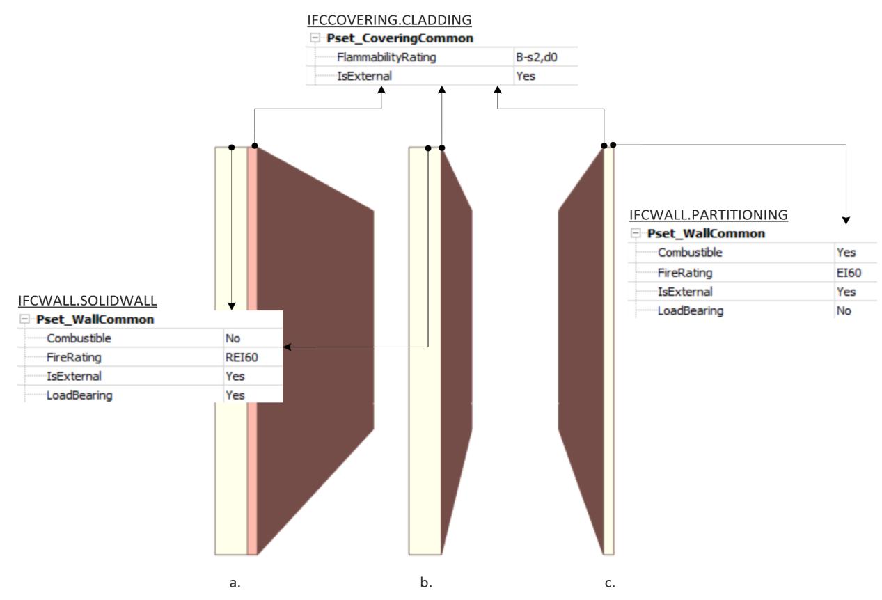
Development of an IFC data model for Fire Prevention Checking 96
Figure 58 | Export of Pset_CoveringCommon and Pset_WallCommon
At this point the software in charge of Code Checking should be able to take for each room all the IfcCovering entities and verify that the compiled value of FlammabilityRating is actually the one provides by the standard or at class lower to be in favour of safety. However, Table 17 shows that for each type of building element, the material groups have a different minimum class and can have both Italian and European classification. Therefore, the software should be able to implement an algorithm that takes into account all these variables.
There are two alternatives for implementing the code checking algorithm, both of which use relationship classes linking the coverings with the spaces they are in: IfcRelSpaceBoundary and IfcRelCoversSpaces. The IfcRelSpaceBoundary (Figure 59) is defined as an objectified relationship that handles the element to space relationship by objectifying the relationship between an element and the space it bounds. It is given as a one-to-one relationship but allows each element (including virtual elements and openings) to define many such relationship and each space to be defined by many such relationships. In general, two basic types of space boundaries are distinguished: 1st level space boundary, defined as boundaries of the space, not taking into account any change in building element or spaces on the other side, and 2nd level space boundary, defined as boundary taking any change in building element or spaces on the other side into account. It can be further distinguished into. In the case of the reaction to fire, what counts is that the space boundary is defined totally from inside the space. This is a 1st level space boundary. The objectified relationship, IfcRelCoversSpaces (Figure 60), relates a space object to one or many coverings, which faces (or is assigned to) the space41
On the one hand, the IfcCovering inherits from the IfcElement class the inverse attribute ProvidesBoundaries, therefore, through the relationship IfcRelSpaceBoundary it is possible to define which spaces the coverings define the perimeter of. Then based on the performance level associated with the space and the type of covering the maximum fire reaction is checked (Figure 61). The second procedure is to use a relationship created ad hoc for the IfcCovering class: IfcRelCoversSpaces. The logical procedure to implement an algorithm for Code Checking (Figure 62) is the same shown in the previous algorithm flowchart, only the input relationship used to obtain the list of coverings and the space they cover changes. To date, the two applications analysed (Graphisoft Archicad 24, Autodesk Revit 2021) use the IfcRelSpaceBoundary relationship to relate the coverings to the spaces, while the latter cannot be exported. Figure 63 shows an export test, the result is the same for both software.
Continuing, Section S.1 of the Code states that:
Deemed-to-satisfy solutions allow that floor coverings, installed on walls or floors, included in group GM4, are permitted for an area ≤ 5 % of the gross internal area of the escape routes or rooms of the activity (i.e., the sum of the gross surfaces of the ceiling, wall, floor, and openings of the room). (Annex I Ministerial Decree 12 April 2019 - S.1.4 comma 3)
In addition to the IFC parameters required for the previous code check, this rule requires knowing two geometric properties: the gross area of rooms and the gross surfaces of ceiling, wall,
41 Whereas the IfcRelCoversBldgElements relationship is an objectified relationship between an element and one to many coverings, which cover that element.
Analysis, mapping of Information Requirements and Building Model Preparation 97
floor, openings). The Gross area of a room is mapped through the property GrossPlannedArea of Pset_SpaceCommon while to map the surface of two-dimensional elements the Quantity Sets of the classes are useful. In the Qto_CoveringBaseQuantites there is the quantity NetArea which corresponds to the sum of all net areas of the covering facing the space. All openings that are included in the covering are subtracted. The Quantities Set of the IfcDoor class also has the quantity Area which is the total area of the outer lining of the door, however, the door class does not have the property FlammabiltyRating as mentioned above. In any case, faced with the possibility of creating a user-defined Property Set to attribute the missing parameter to the IfcDoor class, the algorithm testing this procedure should obtain from the model the fire reaction property, the area of the elements covering the space and calculate 5% of the floor area of the room.
The last focus is on furniture. The European Standards, assuming that furniture cannot for any reason be considered as building elements, do not provide for classification as is the case in the Italian classification. For this reason, there is currently no property in IFC for mapping the reaction to the fire of furniture. Therefore, in this case it would be necessary to introduce a property similar to the existing FlammabilityRating also for the entity IfcFurniture. Then with the relation IfcRelContainedInSpatialStructure42 it is possible to verify that the fire class assigned to the furniture is the maximum one required for the performance level assigned to the space respecting the requirements provided in table S.1-5 of the Code.
If the designer adopts the alternative solution, he must demonstrate reduced smoke production and early fire detection so that the occupants' lives are in any event safeguarded and, if applicable, property is protected, by providing for ad hoc design fire scenarios in settings (areas) where materials with the required minimum reaction to fire requirements are not installed.
42 This objectified relationship, IfcRelContainedInSpatialStructure, is used to assign elements to a certain level of the spatial project structure. Any element can only be assigned once to a certain level of the spatial structure. The question, which level is relevant for which type of element, can only be answered within the context of a particular project, and might vary within the various regions.
Development of an IFC data model for Fire Prevention Checking 98
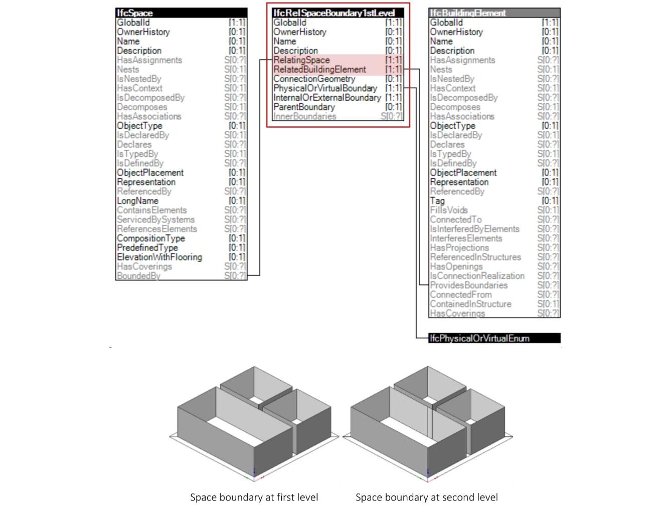
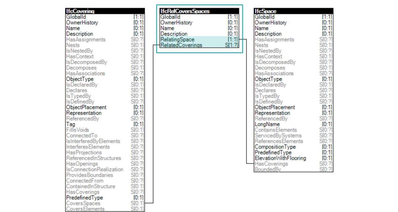
Analysis, mapping of Information Requirements and Building Model Preparation 99
Figure 59 | Space Boundaries 1st Level concept template
Figure 60 | IfcSpaces and IfcCoverings relationship
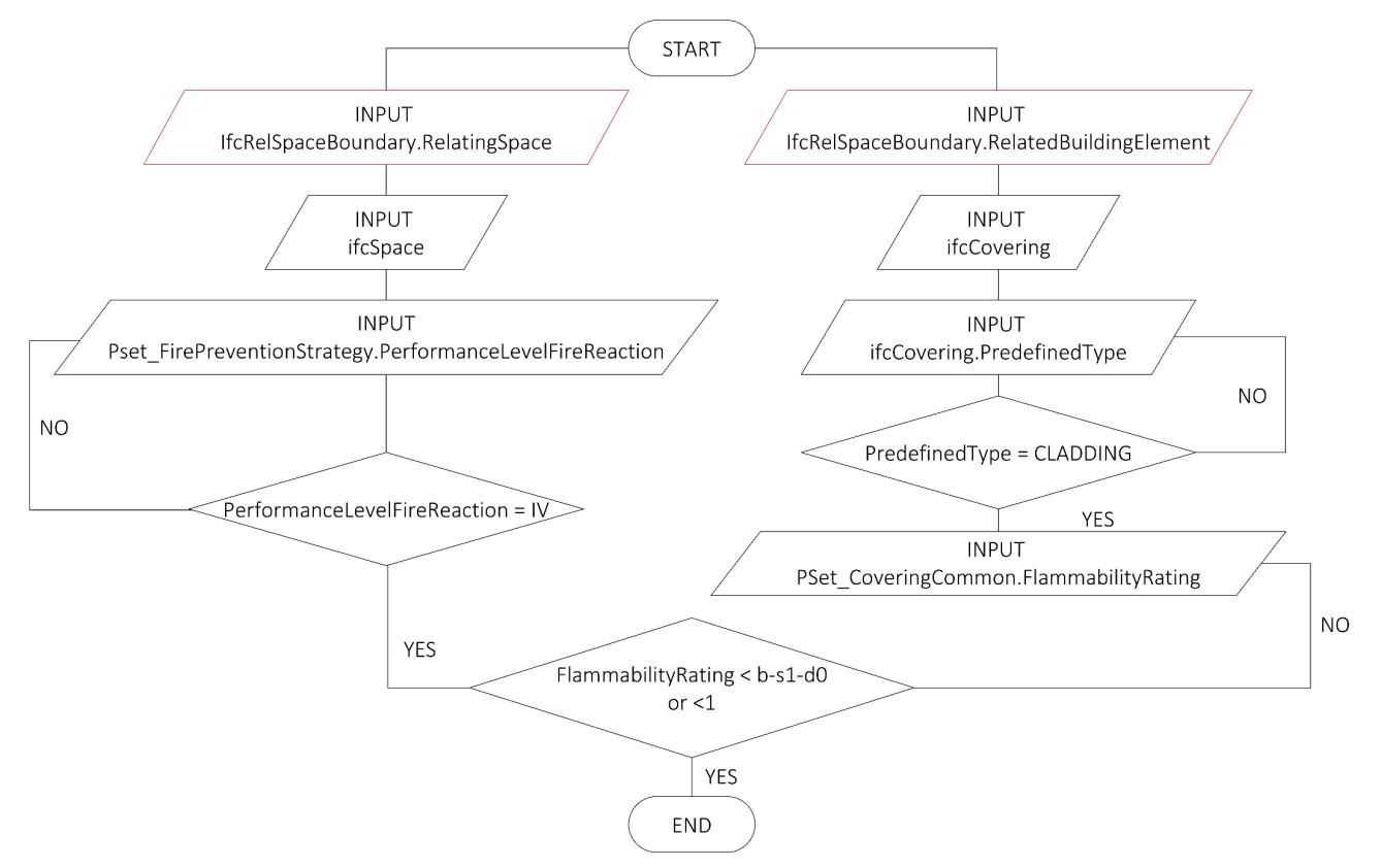
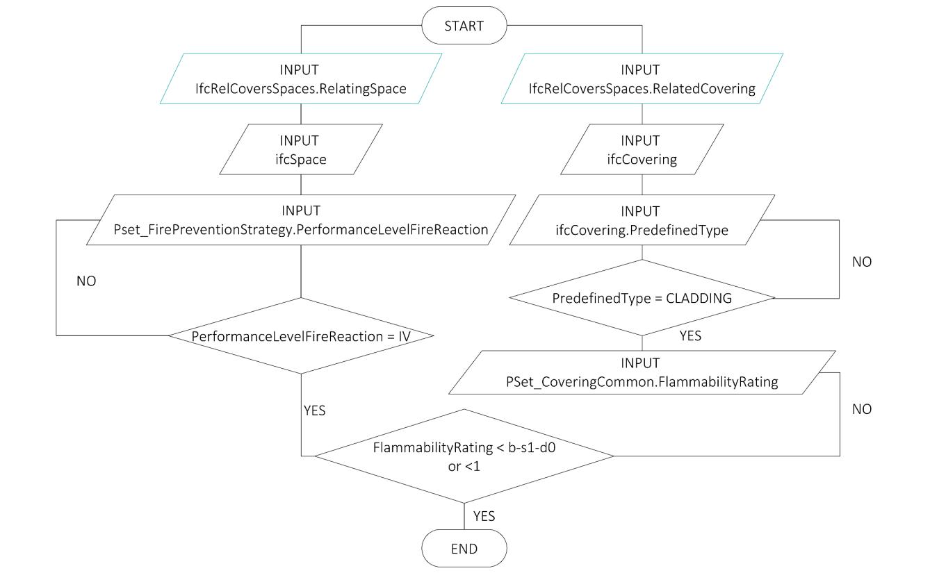
Development of an IFC data model for Fire Prevention Checking 100
Figure 61 | Algorithm Flowchart for fire reaction rule checking (1st procedure)
Figure 62 | Algorithm Flowchart for fire reaction rule checking (2nd procedure)
4.2.8. FIRE RESISTANCE
The fire resistance of structures is a fundamental protective measure to guarantee, in fire conditions, a suitable level of safety for the construction; it concerns the load-bearing capacity of the construction elements and the concept of compartmentalisation, which makes it possible to divide a construction into volumes protected from the effects of fire, reducing the risk of fire spreading to neighbouring areas. This highlights how fire resistance is closely linked to the compartmentalisation strategy (§4.2.9). The performance levels for the fire resistance are defined based on the required state of the building after the end of the fire and the consequences for other neighbouring buildings. If level I does not need any requirements for the structure, except that the possible collapse does not cause damage to neighbouring buildings, level V requires that the structure maintains its full functionality after a fire. The big change introduced by the revision of the Fire Prevention Code in 2019 is to no longer assign a certain level of fire resistance performance to the activity, but to standardise the performance for the entire construction (Annex I Ministerial Decree 12 April 2019S.2.2). This means that in this case, the PerformanceLevelFireResistance property contained in the Property Set Pset_FirePreventionStrategy is assigned to the IfcBuilding. The assignment of the performance level depends on several inputs including:
If the activity is compartmented with respect to other structures that may be adjacent and structurally separate from it such that any structural collapse does not
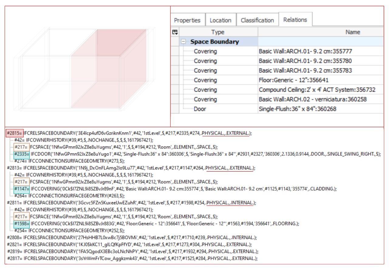
Analysis, mapping of Information Requirements and Building Model Preparation 101
Figure 63 | IFC export of space boundary
damage other structures;
The number of activity managers of the activities in a building;
If the activty does not require the presence of occupants, except for occasional staff for brief periods of time;
The Rlife risk profile of the activity; Rprop risk profile of the activity;
The crowding density of the activity;
The maximum elevation of the above ground and under-ground floor; If the activity is not generally intended for occupants with disabilities; The design fire load.
The parameters listed above are all fillable in an IFC model except for the first one which is a very generic concept and difficult to parameterize. The definition of activity managers, risk profiles and the design fire load has already been dealt with in the previous chapters. On the other hand, to distinguish the activities that require the daily presence of occupants from those for which the presence of occupants is not foreseen, IFC does not provide a property but an alternative way could be to compile the OccupancyNumber property (of the Property Set Pset_SpaceOccupancyRequirements) with a null value. The crowding density of the activity is instead mappable through the property AreaPerOccupant of the same Property Set mentioned above. This last property corresponds in fact to the reciprocal of the parameter required by the regulations. The presence or absence of disabled occupants is also a concept already present in the IFC standard. In this case, it is associated with the activity as a whole and is therefore mappable with the Boolean property HandicapAccessible present in the Pset_ZoneCommon.
The deemed-to-satisfy solutions for fire reaction strategies are described in Table 21. The compliant solution analysed in this thesis concerns performance level III, which requires the assignment of minimum fire resistance to the elements of the building43 as a function of the fire
43 The fire resistance performances of the analysed building elements are:
Load-bearing capacity (R): Capacity of a structural element to bear present loads for a certain period of time under normalised fire conditions
Seal (E): Capacity of a structural element or structure to stop the passage of smoke and hot gases for a certain period of time under normalised fire conditions
Insulation (I): Capacity of a structural element or structure to stop the passage of heat for a certain period of time under normalised fire conditions. Depending on more or less severe limits to the transfer of heat, this requirement is specialised in I1 or I2. Lack of subscript indication means that the requisite is I2.
Radiation (W): Capacity of a structural element or structure to limit thermal radiation from an unexposed surface for a certain period of time under normalised fire conditions.
Mechanical action (M): Capacity of a structural element or structure to resist the impact of other elements without losing its required fire resistance.
Automatic closing device (C): Capacity to close an opening by a structural element under normalised fire and mechanical stress conditions.
Smoke proof (S): Capacity of a closing element to limit or reduce the passage of cold gases or smoke under normalised test conditions. The requirement is specialised in:
Sa: if the seal to the passage of gases or smoke is ensured at ambient temperature;
Development of an IFC data model for Fire Prevention Checking 102
load If the performance level is assigned to the building, the minimum fire resistance class is defined per compartment because in the generation the fire load is calculated for each compartment and it would not make sense to assign a high fire resistance if there is no need for it.
The FireRating property, introduced in §4.2.7, can be associated to all subtypes of IfcBuildingElement as shown in Table 18. This allows the definition of this property for all building elements whether structural or not. Paragraph S.2.12 of the Fire Prevention Code provides a list of elements for which the fire resistance class must be defined. Leaving aside for this thesis work elements such as ducts or fire dampers, a list of the analysed building elements is given in Table 22 In general, the properties used are in addition to FireRating:
Compartimentation, to define if the elements have fire compartment function; LoadBearing,to define if the elements are structural; SelfClosing, for self-closing doors; SmokeStop, for smoke proof doors.
Figure 64 shows the properties that an IFC model should contain to verify that the fire resistance of the building elements of a compartment corresponds to the minimum one given by the standards and the logical procedure to implement the algorithm for Code Checking. As explained in chapter §4.2.9, the compartment is identified by the entity IfcZone which are groupings of spaces. To check that all elements of the spaces have the minimum fire resistance you the relationship IfcRelSpaceBoundary is used because it relates the spaces to the building elements which define them (walls, ceilings, slabs, doors, windows, etc.).
If the compliant solution proves to be too binding and/or too costly, the code introduces some possible solutions for any performance level. Alternative solutions are allowed, consisting of: compartmentalisation concerning other constructions; absence of damage to other buildings or outside the boundary of the area on which the activity is located, as a result of structural collapse. maintenance of load-bearing capacity in fire conditions for a period sufficient to evacuate the occupants to a safe place outside the construction. The load-bearing capacity must in any case be such as to ensure a safety margin tmarg ≥ 100% - RSET and in any case ≥ 15 minutes.
As the design methods for these solutions are closely related to structural engineering, they have not been analysed in this thesis work.
Analysis, mapping of Information Requirements and Building Model Preparation 103
Sm (or S200): if the seal to the passage of gases or smoke is ensured at both ambient temperature and at 200 °C.
Level Description
I Absence of external consequences due to structural collapse
Assignment criteria
● compartmentalisation with respect to other construction works that may be adjacent and structurally separated from them and such that any structural collapse does not cause damage to other construction works or outside of the border of the area on which the activity is located.
● activities with a single activity manager and with a Rprop risk profile equal to 1;
● no presence of occupants, except for occasional staff for brief periods of time.
Deemed-to-satisfy solutions
● Free open-air separation distance, not less than the maximum height of the building, to other construction works and to the border of the area on which the activity is located.
● No minimum load-bearing capacity performance is required from the construction works under fire conditions, or internal compartmentalisation.
II Maintenance of the fire resistance requirements for a period sufficient for the evacuation of occupants to a safe area outside of the building.
● compartmentalisation structurally separation as for level I
● used for activities relating to a single activity manager and with the following risk profiles:
Rlife included in A1, A2, A3 and A4; Rprop equal to 1;
● crowding density ≤ 0.2 pers/m2;
● not intended for occupants with disabilities;
● all floors located at a height between -5 m and 12 m.
● There must be a free open-air separation distance as provided for in performance level I.
● The minimum fire resistance class must be at least 30 or less, if permitted by performance level III for the specific qf,d design fire load of the compartment in question.
III Maintenance of the fire resistance requirements for a period equal (congruent) to the duration of the fire.
IV Fire resistance requirements such that they ensure, at the end of the fire, there is limited damage to the structures themselves.
V Fire resistance requirements such that they ensure, at the end of the fire, maintenance of the full operational functionality of the structure.
Construction works not included in the other assignment criteria.
● The minimum fire resistance class shall be drawn for each compartment as concerns the specific qf,d as indicated in Table S.2-3.
Upon specific request by the customer, as provided for by the design technical specifications, required by the competent authorities for construction works intended for activities of particular importance.
● The minimum fire resistance class as for level III
● To control damage to compartmentalisation elements, there must be verification deformability limits under of thermal and mechanical loads.
● Joints between compartmentalisation elements must be capable of favouring the movements in fire conditions.
● For the purposes of compartmentalisation capacity, the closure elements of the communication spaces between compartments must be smoke proof (EI S200) and the walls must have additional mechanical resistance (M), for a specific class, as in performance level III.
Development of an IFC data model for Fire Prevention Checking 104
Table 21 | Performance level and assignment criteria. Deemed to satisfy solutions (Annex I Ministerial Decree 12 April 2019 - S.2.4)
S.2.12.1 Load-bearing elements with no fire compartment function
IfcBeam; IfcColumn; IfcWall; IfcSlab; IfcRoof; IfcStair; IfcCovering;
Pset_?Common.Firerating-> IfcLabel
Pset_?Common.LoadBearing-> IfcBoolean
S.2.12.2 Load-bearing elements with fire compartment function
Pset_?Common.Firerating-> IfcLabel
Class REI /REIM/REW
IfcWall; IfcSlab; IfcRoof;
Pset_?Common.LoadBearing-> IfcBoolean
IfcWall; IfcWall.PredefinedType-> IfcLabel
False ceilings with intrinsic fire resistance
IfcCovering; IfcCovering.PredefinedType-> IfcLabel
Pset_CoveringCommon.Firerating-> IfcLabel
Class R/RE/REI
TRUE TRUE
PARTITIONING EI/EI-M/EIW
CEILING; EI
IfcCurtainWall; IfcWall; Pset_?Common.Firerating-> IfcLabel E/EI/EIW
Raised flooring
IfcCovering; IfcCovering.PredefinedType-> IfcLabel
Pset_CoveringCommon.Firerating-> IfcLabel FLOORING; R/RE/REI Systems for sealing through holes and linear joints
Fire-resistant doors and closures (including windowed areas and accessories) and their closure systems
IfcDoor; Pset_DoorCommon.Firerating-> IfcLabel
E/EI/EW
True/False
True/False
Analysis, mapping of Information Requirements and Building Model Preparation 105
Attribute/Pset/Qset Value
Table 22 | Properties of IfcBuildingElement subtypes for Fire Resistance measure
Entity
Pset_?Common.Compartimentation-> IfcBoolean TRUE FALSE
Pset_?Common.Compartimentation-> IfcBoolean
S.2.12.4 Non-load-bearing parts or elements in construction works and pertinent products. Partition walls (including those with non-insulated parts and internal flame trap barriers)
Pset_WallCommon.Firerating-> IfcLabel
Curtain walls and external walls (including windowed areas)
Pset_DoorCommon.SelfClosing-> IfcBoolean
Smoke-proof doors
IfcDoor; Pset_DoorCommon.SmokeStop-> IfcBoolean
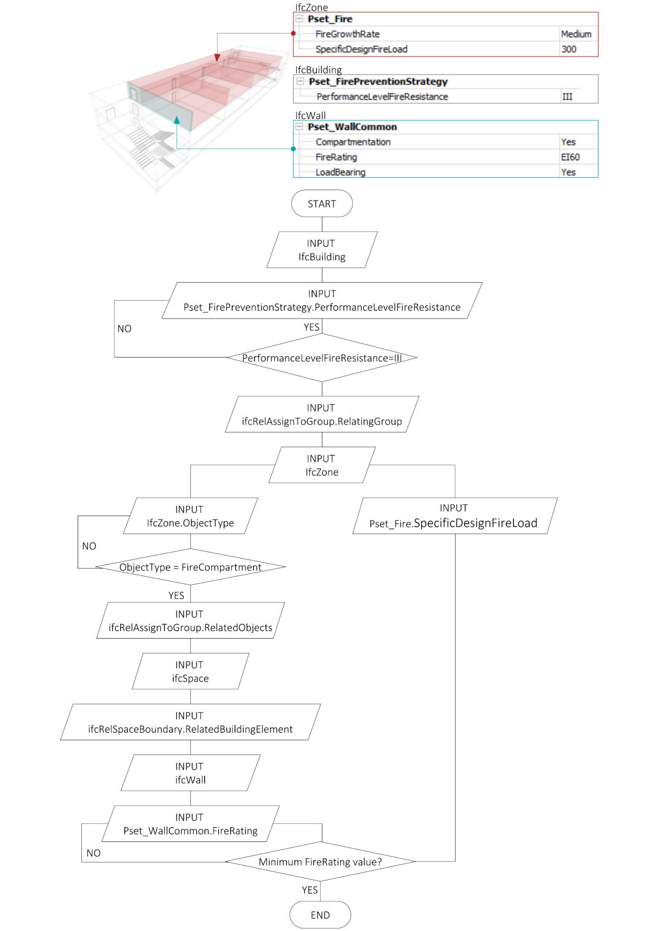
Development of an IFC data model for Fire Prevention Checking 106
Figure 64 | Algorithm Flowchart for minimum fire resistance checking
4.2.9. COMPARTMENTALISATION & ESCAPE RUOTE
From a fire prevention perspective, a building is a collector of functions and spaces intended for circulation. The definition of how these functions is distributed within the building and how they are connected to the circulation spaces intended for the escape of the occupants is of fundamental importance both from a prescriptive design perspective and from a performance perspective. The two fire prevention measures that are most closely linked to the geometric and functional representation of a building are compartmentalisation and escape.
4.2.9.1 COMPARTMENT DEFINITION
The fire prevention measure Compartmentalisation has the function of dividing the construction work into volumes, each of which will allow the possible fire to be kept inside for a predetermined time. To control and contain the spread of fire in the event of a fire within the same activity or between several activities, this measure is carried out either using a suitable physical distance between different structures, with the provision of fire-resistant screens or barriers, or by delimiting the areas with structures with predetermined fire resistance. In addition to internal and external compartmentation, there is also "border" compartmentation. The latter consists of an obligation on the part of the designer to take the necessary steps to limit the spread of fire through the enclosures of the construction work. It is not acceptable for a fire to spread through the facade or roof of a building, thus nullifying internal or external compartmentalisation measures.
The Fire Prevention Code defines the compartment as:
… a part of a construction set up to respond to safety requirements in case of fire; it is delimited by construction products or elements suitable to ensure fire resistance for a given time interval. In the event that no compartmentalisation is provided for, the compartment shall be considered the entire building structure. (Annex I Ministerial Decree 12 April 2019G.1.8 comma 3)
The fire compartment is, therefore, a continuous "cell" for which the fire containment performance within it does not degrade, at least for the time established by the reaction to fire class, in the event of the development of a generalised fire.
For functional requirements, the fire compartment must have openings so that the normal functions in the activity subject to the fire safety design can be carried out. Any communication with other compartments of the activity is achieved using doors that, when closed, guarantee the same tightness and insulation performance as the compartments being communicated. This is the case of fire-resistant doors that offer Seal (E), Insulation (I), and smoke proof performance (Sa o S200). Other elements of "discontinuity" in the compartmentation are represented by the crossings of the technological and service installations 44
44 The Code devotes a whole paragraph to the Continuity of compartments (§ S.3.7.3), providing that all the horizontal and vertical closures of the compartment must form a "continuous and uniform barrier" to prevent the
Analysis, mapping of Information Requirements and Building Model Preparation 107
The concept of compartmentalisation has two different meanings. On the one hand, areas containing certain functions at risk are compartmentalised to limit the spread of fire to other areas of the construction work to reduce the effects that the fire could cause to the structure. On the other hand, the same rooms intended for escape can be compartmentalised to ensure that the fire started in the spaces served by the escape system cannot spread inside. This allows the occupants to evacuate the structure safely. It should also be noted that if a building contains rooms with a negligible fire risk they may not be compartmentalised.
Another important piece of information is the definition of the type of compartment. First, the legislation makes a distinction between the compartment and smoke-proof compartment45. A smoke-proof compartment has the ability of to limit the entry of smoke generated by fire that develops in a communicating compartment. The code proposes several solutions to design a smokeproof compartment in case a fire breaks out in a communicating compartment and to prevent smoke from entering the compartment (Annex I Ministerial Decree 12 April 2019 - S.3.5.3). The compartment can be realised with a differential pressure system (Figure 65a) designed, installed, and operated according to EN 12101-646. This standard specifies pressure differential control systems designed to retain smoke at a physical barrier in a building, such as a door or other similar opening. Two other solutions are to equip the communicating room(s) from which smoke is to be prevented with smoke and heat exhaust systems that trap smoke above the communicating doorways (Figure 65b). The last two solutions involve separating the compartment from the communicating compartments from which smoke is to be prevented with an uncovered space (Figure 65c) or by a smokeproof filter (Figure 65d). The filter is a fire compartment in which the probability of fire ignition and development is considered negligible, due to the absence of fire ignition points and to the low specific fire load admitted. Building elements must have a fire resistance of more than 30 minutes and doors must be smoke-tight. The smoke-proof filter is a filter that can have one of the three characteristics shown in Figure 66 (Sasso, 2019). In the first case, the smoke enters the Smoke Filter Room and is conveyed outside via a chimney directly above the roof. In the second case, smoke does not enter the filter room due to the higher pressure generated by the ventilation system in the filter room, which draws clean air directly from outside. In the last case, the smoke enters the filter room and is conveyed outside through an opening. In the design of the fire safety of an activity, the smoke filter represents an element of "fluid-dynamic disconnection" between two compartments or between a compartment at risk of fire and an escape route (Annex I Ministerial Decree 12 April 2019 - S.3.5.4-5). It is important not to confuse 'smoke-proof filters' with 'smoke-proof compartments', as the first refer to rooms between two compartments and are comparable to 'open spaces', while the second are the compartments themselves.
propagation of the effects of fire.
45 The third qualification is External type (or external): the qualification of a portion of the activity external to the construction works, with the characteristics to temporarily counteract the propagation of fire coming from the construction works.
46 EN 12101-6:2005 “Smoke and heat control systems. Specification for pressure differential systems. Kits”
Development of an IFC data model for Fire Prevention Checking 108
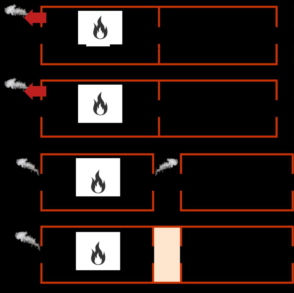
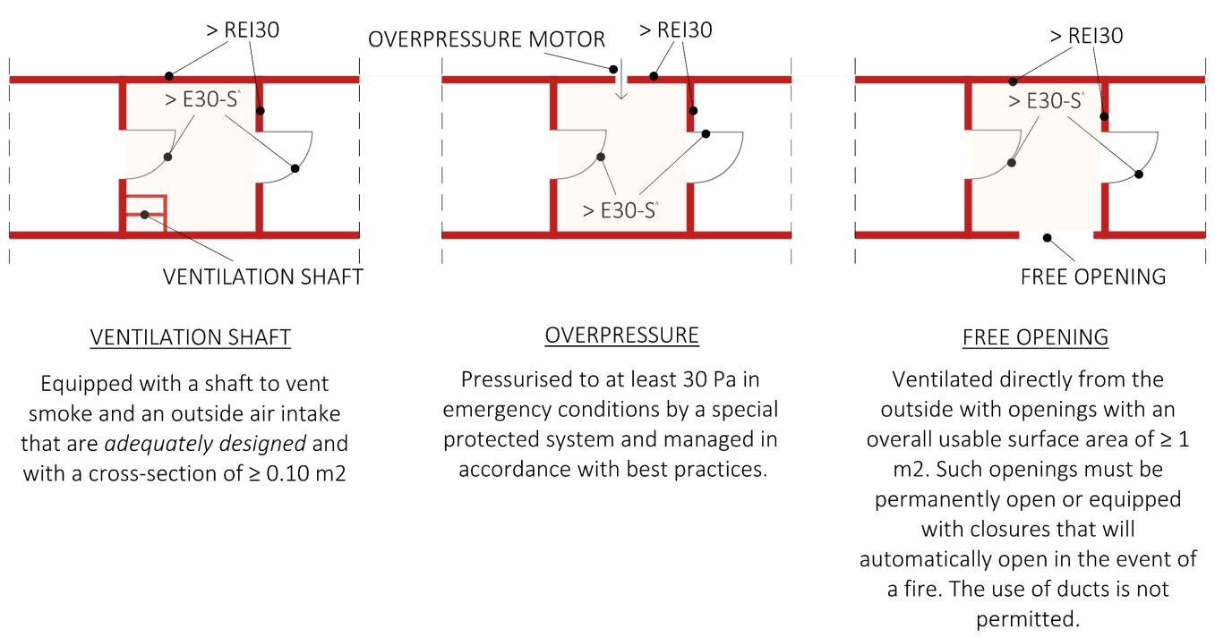
Analysis, mapping of Information Requirements and Building Model Preparation 109
Figure 65 | Examples of smokeproof compartment
Figure 66 | Types of smokeproof filter
To proceed to define the compartments in an IFC model, buildingSMART, proposes two procedures shown in §2.4.3, the first using the IfcSpatialZone class (Genova & Adachi 2020), the second using IfcZone. To make explicit that the IfcZone entity is a compartment, the ObjectType attribute is filled with the value FireCompartment; the attribute Name defines the name of the compartment; finally, the Description attribute allows a short description of the compartment (Figure 68). To group the IfcSpaces that the compartment contains, the IfcRelAssignsToGroup relationship is used (Figure 67). Rather, to explicate that an IfcSpatialZone is a compartment, the enumerative attribute PredefinedType should be used with the value FIRESAFETY and as before the attribute Name defines the name of the compartment. To refer a IfcSpatialZone to the spaces contained, BuildingSMART provides the entitiy IfcRelReferenceSpatialStructure47 The IfcSpatialZone class is not yet correctly implemented in the modelling software analysed. In Graphisoft Archicad 24, it is not possible to export this entity at all. Instead, in Autodesk Revit 2021 no system family is representing the SpatialZone, the only way would be to create with the tool “Area ” a tridimensional object and through the IfcExportAs parameter export the object as an IfcSpatialZone. As shown in Figure 68 it was possible to place the entity within the project spatial hierarchy using the objectified relationship IfcRelContainedInSpatialStructure but it was not possible to relate IfcSpace entities and IfcSpatialZone with IfcRelReferencedInSpatialStructure relationship. Furhtermore, we were not able to define properties for the entity IfcSpatialZone In fact, this entity, although still in the development phase (§2.4.3) and not completed implented in BIM authoring software could be defined by the Property Set Pset_SpaceOccupancyRequirements and Pset_SpaceFireSafetyRequirements which is fondamental in the fire prevention design. We have tried to add the properties from the Project Parameters window to the Areas system family and to define the Property Sets by accessing the Modify Setup of IFC for REVIT. There was no success in either spitting out Export IFC common property sets or subsequently defining the Property Sets using the text file provided by Revit (Figure 69) From now on we will continue analysing the first of the two procedures, using the IfcZone class.
47 . Physical elements that are referenced by this spatial zone are related using the IfcRelReferencedInSpatialStructure relationship as it is a non-hierarchical assignment in addition to the hierarchical spatial containment within a subtype of IfcSpatialStructureElement. Also, spaces, that referenced by this spatial zone are related using the IfcRelReferencedInSpatialStructure relationship. The IfcSpatialZone itself can also be referenced by another spatial element using IfcRelReferencedInSpatialStructure.
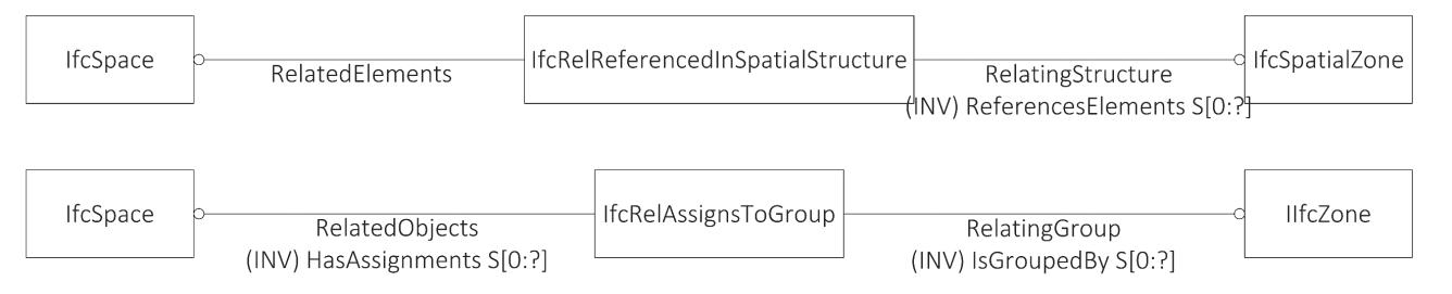
Development of an IFC data model for Fire Prevention Checking 110
Figure 67 | Comparison between IfcSpatialZone e IfcZone
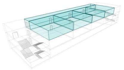
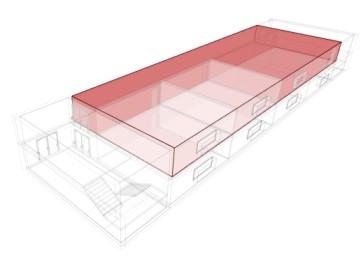
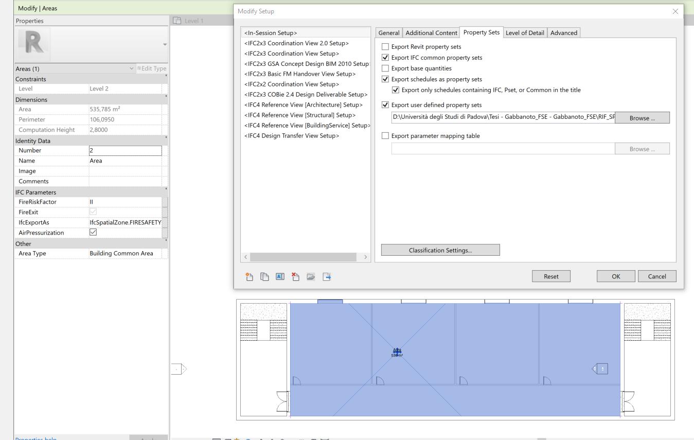
Analysis, mapping of Information Requirements and Building Model Preparation 111
Figure 68 | IfcZone IfcSpatialZone in STEP file exported from Autodesk Revit 2021
Figure 69 ! IFC for Revit Modify Setup
To be able to describe the subsequent steps, two more relationships are introduced. Since the class IfcZone is a grouping of spaces without its geometry, to obtain the elements along the perimeter of the spaces, we must use the relationship IfcRelSapceBoundary which relates each space to the physical elements around it (IfcWall, IfcDoor...). Whereas the insertion of a door into a wall is represented by two separate relationships. First the door opening is created within the wall by IfcWall< IfcRelVoidsElement > IfcOpeningElement, then the door is inserted within the opening by IfcOpeningElement < IfcRelFillsElement > IfcDoor (Figure 70).
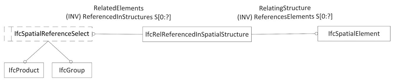
Another concept that an IFC model should make explicit is whether the compartment is smoke-proof or not. To date, there is no parameter in IFC that tells me whether the compartment is smoke-proof. Among the cases shown in Figure 65, only the case in which a compartment is smokeproof because it is equipped with a differential pressure system can be mapped in the IFC model
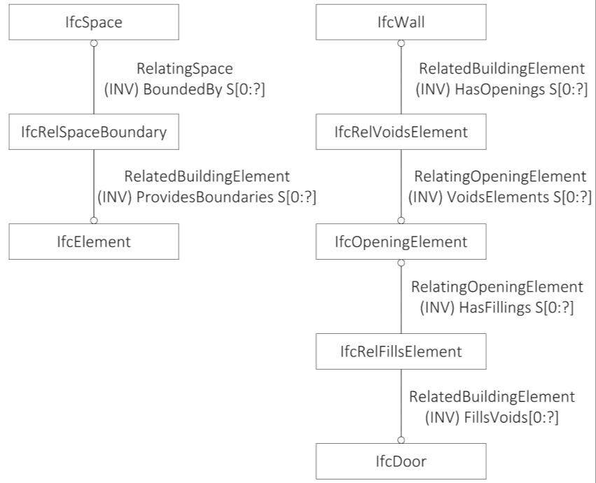
Development of an IFC data model for Fire Prevention Checking 112
Figure 70 | EXPRESS-G diagrams: IfcRelAssignsToGroup, IfcRelSpaceBoundary, IfcRelVoidsElement and IFcRelFillsElement
Figure 71 | IfcRelServicesBuildings (IFC4.1) & IfcRelReferencedInSpatialStructure (IFC4.3)
through the property AirPressurization of the Pset_SpaceFireSafetyRequirements. This Boolean property serves to indicate whether the IfcSpace or IfcZone entity is required to have pressurised air (TRUE) or not (FALSE). For the other cases of smoke-proof compartments, an attempt was made to make assumptions with the available IFC dataset. One of these is that the compartment has a smoke and heat exhaust system. This concept is mappable in IFC through the class IfcDistributionSystem. A distribution system is a network designed to receive, store, maintain, distribute, or control the flow of a distribution media. The group IfcDistributionSystem defines the occurrence of a specialized system for use within the context of building services. Important functionalities for the description of a distribution system are derived from existing IFC entities. From IfcSystem it inherits the ability to couple the distribution system via IfcRelServicesBuildings to one or more IfcSpatialElement subtypes. In IFC4.3, the functionality of IfcrelSevicesBuildings had been combined into IfcRelReferencedInSpatialStructure, so that any product or system can be referenced in a spatial structure. But now IFC4.3 is not the offical release of IFC is still a candidate. From IfcGroup it inherits the inverse attribute IsGroupedBy, pointing to the relationship entity IfcRelAssignsToGroup. This allows to group distribution elements (instances of IfcDistributionElement subtypes), and in special cases ports directly (instances of IfcDistributionPort).With the IfcRelServicesBuildings property (Figure 71), one or more spaces can be related to the distribution system that allows to disposal of smoke and heat present in them in case of fire. An example of this is shown in Figure 73 even if with the Autodesk Revit 2021 software it was not possible to relate the property with the IfcSpace entity but with the IfcBuilding entity. The case where the compartment is separated from others by an open space could be expressed by checking that the outer walls of a compartment contain external doors. You should take in consideration all the spaces contained in a compartment, obtaining the space boundaries of the spaces in particular the walls, filtering the walls according to the property Compartimentation and then through the relationships IfcRelVoidsElement and IfcRelFillsElement obtaining all the IfcDoors that are at the exit of a compartment. At that point, you should verify that the list of doors obtained has value TRUE for the property IsExternal (Figure 74) The last case is the smoke-proof compartment which is such because it is separated from other compartments by a smoke-proof filter (Figure 75). In this case, with the same procedure as before, the doors at the exit of the compartment are obtained (in this case without filtering them according to the IsExternal value), it is verified that they are smoke proof with the Smokestop property and then that they have at least a fire resistance class of E30. At this point, it is verified that they are access doors to a particular IfcSpace (through the IfcRelSpaceBoundary relation) which should have attributes to show if it is a smoke-proof filter. If the filter is smoke-proof due to the presence of a ventilation duct (Figure 75.1), it is useful to use the IfcRelServicesBuildings relationship (or when this is no longer available IfcRelReferencedInSpatialStructure relationship) to relate one or more IfcSpaces to an IfcZone48 (his time with the RunningDuct value for the ObjectType attribute which is a collection of vertical airspaces) (BuildingSMART International, 2020b). If the filter is pressurised it will have the AirPressurization property of property set Pset_SpaceFireSafetyRequirements (Figure 75.2). Finally,
48 This is possible because the class IfcZone is a subtype of ifcSystem and therefore inherits from it the relationship IfcRelServicesBuildings (or IfcRelReferencedInSpatialStructure with the future version of IFC).
Analysis, mapping of Information Requirements and Building Model Preparation 113
if the filter is smoke-proof due to the presence of a window with an area of at least 1m2 and with automatic opening, then the IfcSpace entity shall be related through the IfcRelSpaceBoundary class to an IfcWindow entity that has: a value greater than 1m2 the Quantity Area contained in the Quantity Set Qto_WindowBaseQuantities, and the property HasDrive, which indicates whether this object has an automatic drive to operate it (TRUE) or no drive (FALSE), set with the value TRUE (Figure 75.3). Anyway, defining through the ObjectType attribute if the zone is a smoke-proof or only protected compartment makes possible a clear distinction in the IFC model of the two types of compartments. Even if we use the entity IfcSpatialZone the ObjectType parameter should be filled because the PredefinedType proprose by BuildingSmart, FIRESAFETY, is generic. The same thing should be done to define a space as a smoke-proof filter. In the case of the ifcSpace entity the ObjectType parameter BuildingSMART declares that the ObjectType should hold the space type, i.e., usually the functional category of the space. The definition of the category and the function of the space in terms of the fire safety of the building conflict with each other. For example, a filter can be a corridor or a staircase. In that case, the ObjectType attribute should contain the value CORRIDOR or STAIRCASE and the parameter could not be used to define if that space is a filter. From this, we can see that for certain aspects the IFC standard is not yet mature under the aspect of fire prevention and that it needs implementations. Making assumptions based on the existing IFC Dataset, you could think of using the relationship IfcRelAssignToProduct to map the relationship between the compartments and spaces (Figure 72).
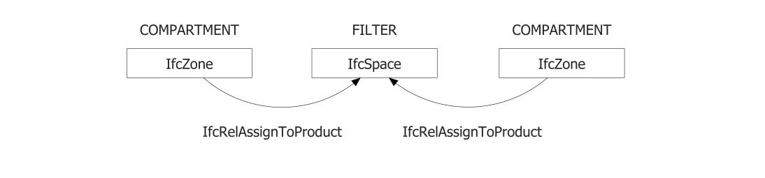
Development of an IFC data model for Fire Prevention Checking 114
Object Ifc Entity ObjectType attribute value Fire Compartment IfcZone / IfcSpatialZone FireCompartment Smoke-proof Compartment IfcZone / IfcSpatialZone SmokeProofCompartment
Table 23 | IfcZone/ifcSpatialZone ObjectType for Compartments
Figure 72 | Proposal relationship between the ompartment and spaces
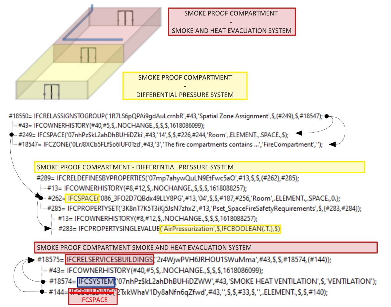
Analysis, mapping of Information Requirements and Building Model Preparation 115
Figure 73 | Smokeproof Compartment in IFC: differential pressure system and smoke and heat evacuation
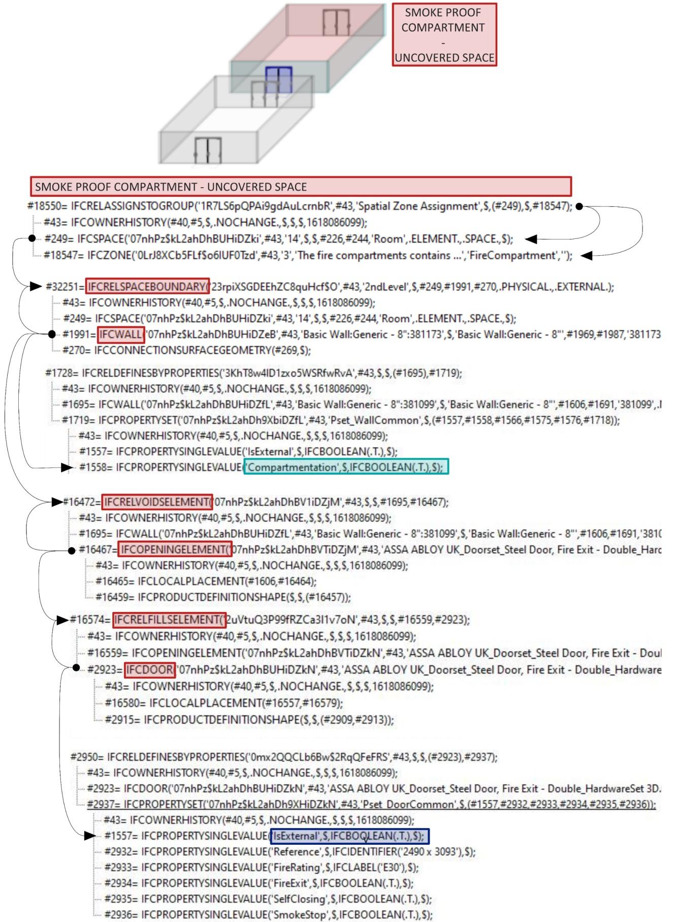
Development of an IFC data model for Fire Prevention Checking 116
Figure 74 | Smokeproof Compartment in IFC: Uncovered spaces
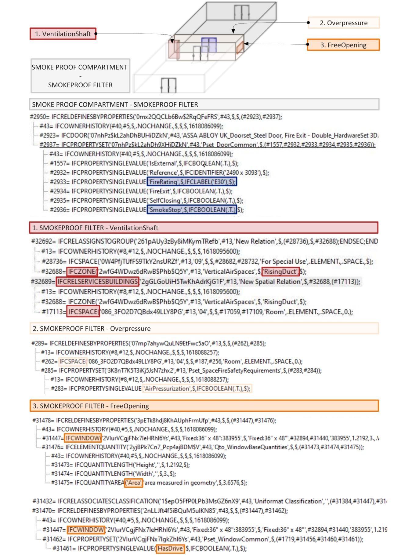
Analysis, mapping of Information Requirements and Building Model Preparation 117
Figure 75 | Smokeproof Compartment in IFC: Smokeproof Filter
4.2.9.2 DATA FOR COMPARTMENT DESIGN
In the following, the information a fire protection designer must assign to a compartment to carry out code checking are investigated.
The revision of the Fire Prevention Code in 2019 introduced the obligation to assign the level of compartmentation performance no longer to the individual activity but to standardise the performance to the entire construction work (Annex I Ministerial Decree 12 April 2019 - S.3.2). This means that in this case, the PerformanceLevelCompartmentation property contained in the userdefined Property Set Pset_FirePreventionStrategy is assigned to the IfcBuilding.
The subdivision of activities and volumes within an activity through compartments corresponds to the design solution proposed for both performance level II and III of the Compartmentalisation Strategy (Annex I Ministerial Decree of 12 April 2019 - S.3.3). In addition to the latter, the elements used to compartmentalise must also be smoke proof in addition to having a certain fire resistance. The general rules of good compartment design set out in the section on compartmentalisation strategy are for example the maximum gross floor area that a fire compartment can have about its height and risk profile, the separation distance in open space between activities and the cases where multi-storey compartmentation is possible. Below are two prescriptive rules associated with the compartment and its components
The minimum fire resistance class shall be drawn for each compartment as concerns the specific qf,d as indicated in TableS.2-3. In the event that the specific fire load qf,d of the design does not specify a minimum fire resistance rating, the compartment is not required, unless a minimum fire resistance rating is otherwise expressly prescribed. (Annex I Ministerial Decree of 12 April 2019 - S.3.7 comma 1)
The grosssurfaceareaofthe compartments mustnot exceedthemaximumvaluesstipulated in Table S.3-6 . (Annex I Ministerial Decree of 12 April 2019 - S.3.6.1 comma 3)
In the first case, the fire load information associated with the compartment defines what is the minimum fire resistance class of the compartment elements, in the second case the compartment elevation and the Rlife risk profile define what is the minimum compartment area.
In general, the concept underlying these solutions is that it must be demonstrated, with analytical models, that no fire propagation occurs in the configuration considered and that the protection of the lives of the occupants is guaranteed (Annex I Ministerial Decree of 12 April 2019M.3) and, if applicable, the protection of assets by assessing the propagation of smoke throughout the activity and ensuring the escape using the ASET/RSET methodology49
49 The performance-based design of the escape route system consists essentially in the calculation and comparison of two time intervals: ASET (available safe escape time) and RSET (required safe escape time). The evacuation
Development of an IFC data model for Fire Prevention Checking 118
It follows that information on the geometry of the subdivision, and the characteristics of the subdivision are essential. In a prescriptive view information such as the gross area of the compartment will be compared with the maximum required by the regulations. From a Fire Safety Engineering (FSE) perspective the geometry of activity, the compartments and the escape routes influence the evacuation of the occupants, the development of the fire and the spread of combustion products and its definition is fundamental to study fire scenarios and demonstrate through analytical models how a potential fire develops within a compartment or how the occupants escape.
The first proposed focus is on the geometric information of a compartment. Table 24 lists this information with references and definitions.
Reference Information
Definition
Compartment reference floor
Floor of the external location toward which the evacuation of the occupants of the compartment will primarily take place and from which the rescuers will gain access. If there is no such floor with these characteristics, then the floor where rescuers access the area with the best operational fire safety characteristics shall be considered (Chapter S.9). Each compartment shall have a single reference floor determined, which will generally correspond with the public or private access roadway. Determination of the compartment reference floor shall be noted in the design.
G.1.7
Compartment elevation
The difference between the level of the compartment floor and its reference floor. In the case of a multi-floor compartment, the greatest height difference shall be assumed as the absolute value. (e.g. for the highest compartment floor above ground, or for the lowest compartment floor below ground level).
Above-ground compartment or floor Compartment with a positive height.
Underground compartment or floor Compartment with a negative height.
Gross floor area
Available floor area of ventilation openings
A plan view floor area within the internal perimeter of the walls delimiting the setting.
Floor area of the opening measured less any obstructions (e.g. frame, grate, fins, etc.).
The definition of Compartment reference floor and Compartment elevation requires a focus to better understand why it is necessary to associate this information with the compartment. The definition of the compartment reference floor is used for two main reasons. On the one hand, to understand the floor from which the occupants exit, to monitor the length of the escape routes and
system is considered to be effective if ASET > RSET, that is, if the time in which non-incapacitating environmental conditions remain for the occupants is greater than the time necessary for them to reach a safe place, and not be subject to such unfavourable environmental conditions due to the fire.
Analysis, mapping of Information Requirements and Building Model Preparation 119
Table 24 ! Geometry of compartment
to define at which level the safe place is located. On the other hand to describe the fire-fighting operation to monitor how the accessibility is guaranteed for the rescuers of the activity and to calculate the compartment elevation (Figure 76). The second case draws attention to the aspect of accessibility of the rescuers to the inside of the building using the escape routes when it is not possible to approach the vehicles From what has been said it emerges that a reference plan should contain two levels of information, the first referring to the fact that the exit/entrance level is vehicular, pedestrian or vehicular and pedestrian, the second to which level this refers. Figure 77 shows some examples proposed by the standard, from the simplest case where there is a single-entry level coinciding with the occupants' exit level and the rescuers' entry level to the most complicated case where there may be several entry levels indifferently indicated as vehicle access levels and exit levels. The immediate consequence of this definition should lead to the definition of compartment elevation. From a fire prevention point of view, the height of the compartment corresponds to the difference in height between the floor on which the compartment is located and the reference floor of the latter and is, therefore, a relative height. If it is possible to have a multi-storey compartment, the greater height difference is taken into account. The definition of the reference floor is a concept that is also applied to all the floors of buildings because not all the spaces in a building are compartments, therefore, it is necessary to generalise the definition of the reference floor to the levels of the building before the compartments.
Finally, the concept of the access floor for rescuers is also associated with the definition of “fire prevention height”. The original definition from Ministerial Decree 30/11/1983 is related to the heights that can be handled by the fire brigade's ladder truck, which can handle a height of approximately 24 meters. For this reason, the definition takes into account two elements: the lowest possible external level where the ladder truck can be found; the highest possible window or balcony threshold, since this is where the ladder truck can rest, to evacuate the people present and allow the fire brigade to enter the building. The code has partly revised this definition by excluding the counting of the height of the window on the top floor of the building.
Fire prevention height: maximum floors height of the activity. Floors that are occupied only occasionally and for brief periods, such as equipment floors and rooms, are excluded. (Annex I Ministerial Decree of 12 April 2019 – G.1.7 comma 4)
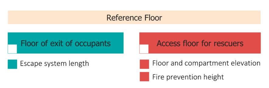
Development of an IFC data model for Fire Prevention Checking 120
Figure 76 | Reference floor
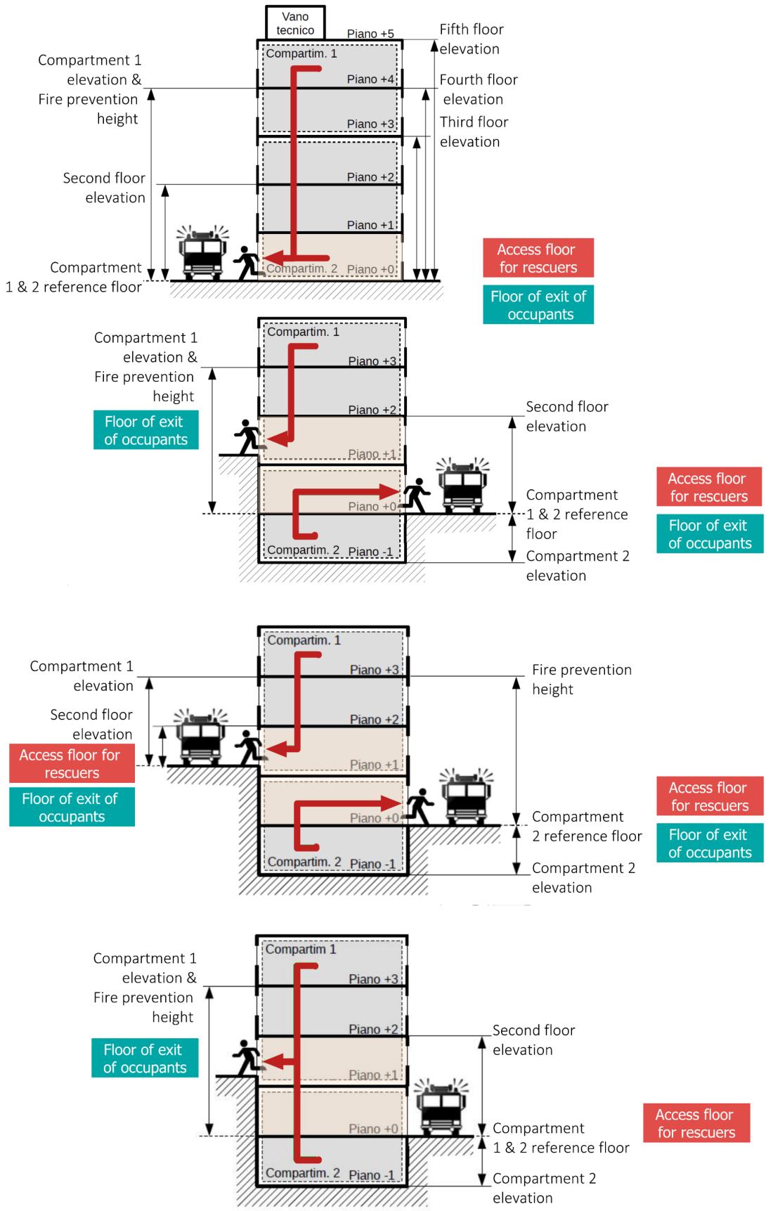
Analysis, mapping of Information Requirements and Building Model Preparation 121
Figure 77 | Examples of the determination of the fire prevention height, floor and compartment height, cross-section (source: Decreto Ministeriale 12 Aprile 2019)
To date, the IFC standard does not have a property to define an exit floor. Figure 78 shown an assumption made considering the existed dataset of IFC. The property that makes a floor of the building the final exit level of the occupants is translated into the presence or absence in the floor of an emergency door that is external. Therefore, it could be indirectly mapped in an IFC model that an IfcBuildingStorey is the reference floor for the occupants exit verifying that, through the relation IfcRelContainedInSpatialStructure50 , in it are present the IfcDoor entities with the FireExit and IsExternal properties of the Pset_DoorCommon with value TRUE. To define whether an IfcBuildingStorey allows access by rescuers, the EntranceLevel property may be used. This property is necessary but not sufficient; in fact, it would be necessary to define whether the building storey is a driveway or pedestrian access level. The definition of an enumerative attribute associated with the IfcBuildingStorey class may help by defining a list of level types (e.g., architectural level, structural level, entrance level etc). More simply the definition of a boolean property like IsDriveWayEntrance grouped under the Pset_BuildingStoreyCommon as shown in Figure 78 can solve the gap that the IFC standard presents today. Since the access and exit levels have been defined, we move on to define which of these levels are the reference levels for the compartments and the other floors of the building. As regards the relationship between a compartment and the final exit leading to a safe place, reference should be made to next paragraph on the escape route. For the definition of the reference plan instead in Figure 79 we propose an assumption that has been made with the existing dataset. The idea is to map the reaction between the access level of the rescuers and the evacuation level with the relation IfcRelAssignsToProduct. The objectified relationship IfcRelAssignsToProduct handles the assignment of objects (subtypes of IfcObject) to a product (subtypes of IfcProduct). The Name attribute should be used to classify the usage of the IfcRelAssignsToProduct objectified relationship. It is possible to apply this relationship since IfcBuildingStorey is a subtype of the ifcProduct class which in turn is a subtype of the IfcObject class, while the IfcZone class is a subtype of the IfcObject class. Therefore, the two entities representing respectively a floor of a building and a compartment inherit from the supertype the inverse attributes that relate them to each other through the ifcRelAssignsToProduct class.
Based on the above assumptions, it is possible to proceed with the definition of the elevation of a compartment or a floor. The IfcBuildingStorey entity has the Elevation attribute that corresponds to the elevation of the base of this storey, relative to the 0.00 internal reference height of the building. The 0.00 level is given by the absolute above sea level height by the ElevationOfRefHeight (Figure 80) attribute given at IfcBuilding which is usually the top of construction slab (Figure 81). This attribute however does not correspond to the elevation of a storey concerning the reference floor as defined by the Italian regulations because the reference floor may be at a different elevation from the zero elevation as shown in Figure 81. For this reason, in order to calculate the correct elevation required for fire prevention purposes, it is necessary to proceed following the logical steps proposed in Figure 82, if one wants to define the elevation of a floor, or those in Figure 83 if one wants to define
50 This objectified relationship, IfcRelContainedInSpatialStructure, is used to assign elements to a certain level of the spatial project structure. Any element can only be assigned once to a certain level of the spatial structure.
Development of an IFC data model for Fire Prevention Checking 122
the elevation of a Compartment. Also, the IFC translation of the fire prevention height is based on the same assumptions made previously51 It is obtained by making the difference between the elevation of the IfcBuildingStorey which is the reference and the highest IfcBuildingStorey.
51 The latest version of IFC4 has only two parameters defining the heights of a building: total height of building, also referred to as ridge height (top of roof structure, e.g the ridge against terrain): provided by BaseQuantity TotalHeight, eaves height of building (base of roof structure, e.g the eaves against terrain): provided by BaseQuantity with Name=EavesHeight.
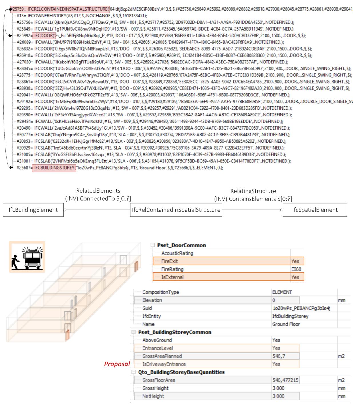
Analysis, mapping of Information Requirements and Building Model Preparation 123
Figure 78 | IFC Mapping of reference floor
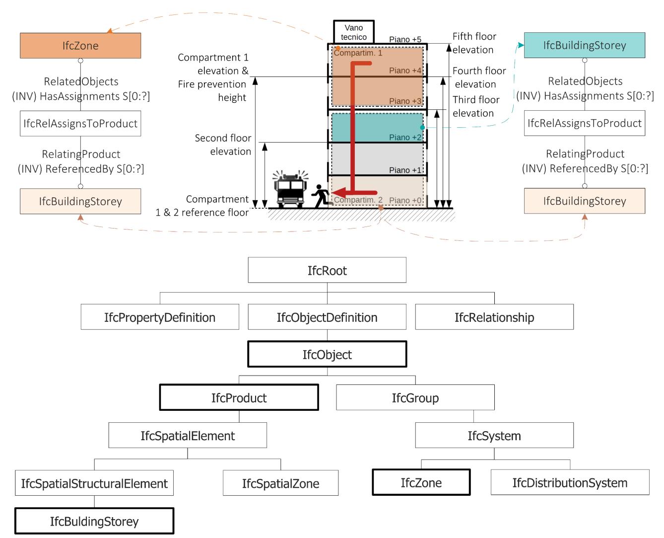
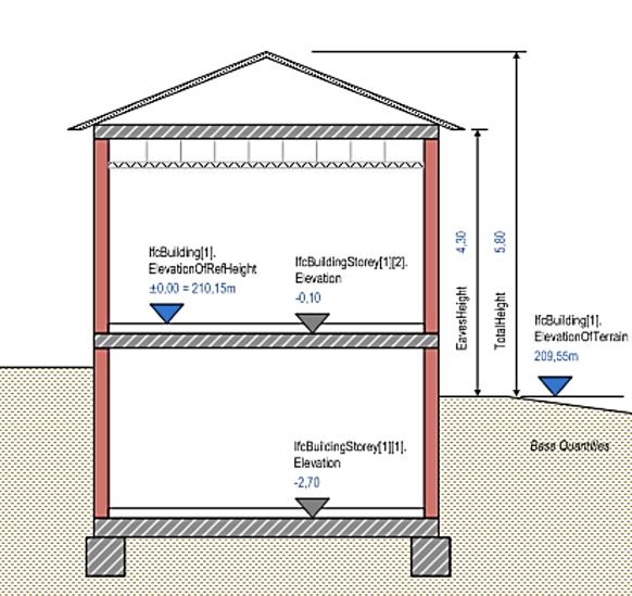
Development of an IFC data model for Fire Prevention Checking 124
Figure 79 | IFC Mapping of Reference Floor: assumption with existed DataSet
Figure 80 | Building elevations
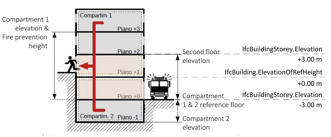
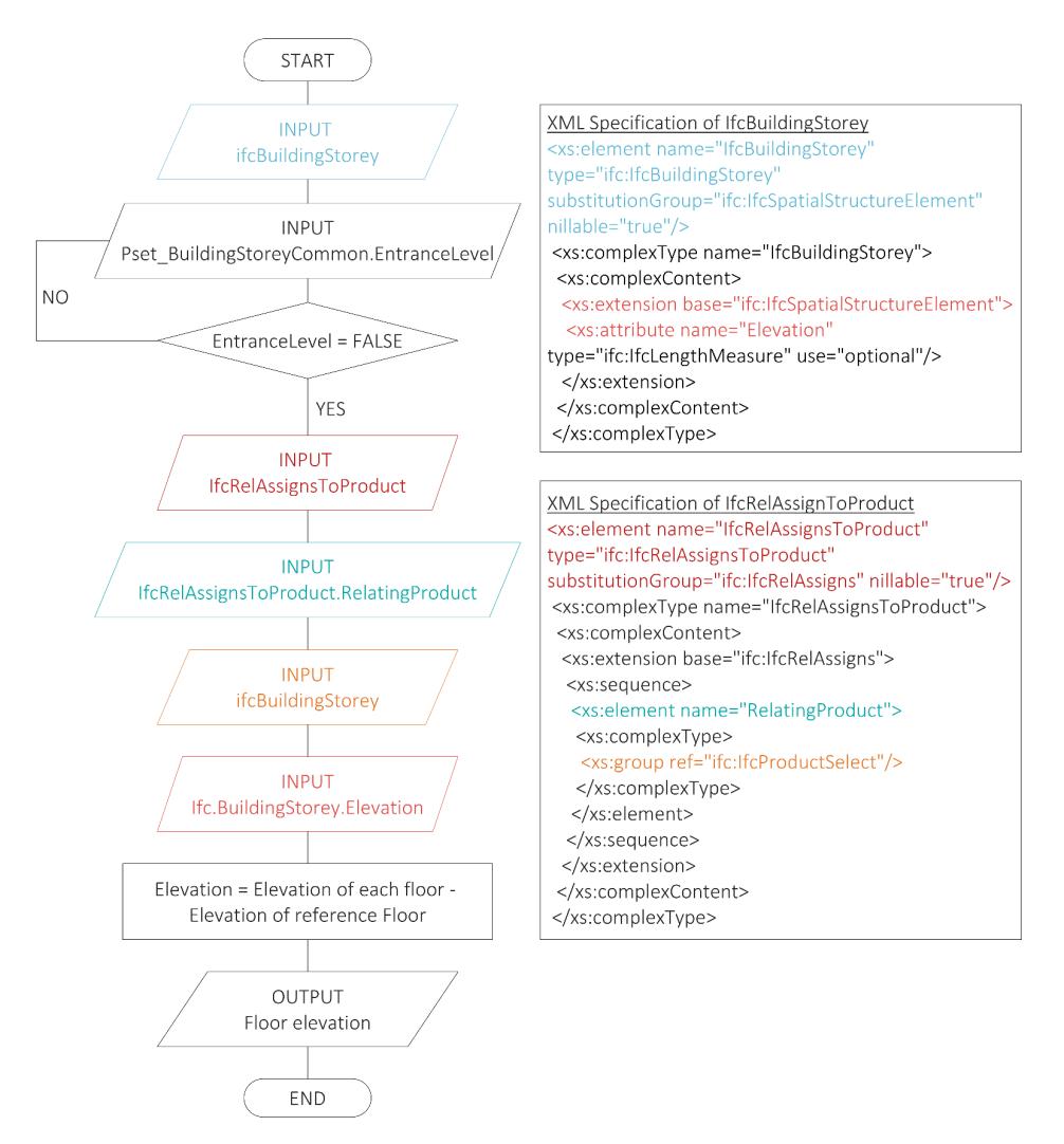
Analysis, mapping of Information Requirements and Building Model Preparation 125
Figure 81 | Relative elevation of an IfcBuildingStorey entity
Figure 82 | Algorithm Flowchart for Floor elevation
The last focus concerns the gross area of the compartment. As mentioned above the class IfcZone does not have its geometry and therefore does not have its own Quantity Set. Among the properties of the Property Set Pset_ZoneCommon it has the property GrossPlannedArea which provides the total planned gross area for the zone. The possibility of calculating this data with an automated procedure would allow an automatic update of the value if there were changes in the geometry of the model during the design phase. The value to be calculated is the sum of the gross areas of the spaces included in the room. Figure 84 shows how we automated the procedure with the Dynamo tool, the Visual scripting environment of Autodesk Revit 2021 The property of the IfcSpace entity used to map the gross area of space in an IFC model is found in the Property Set
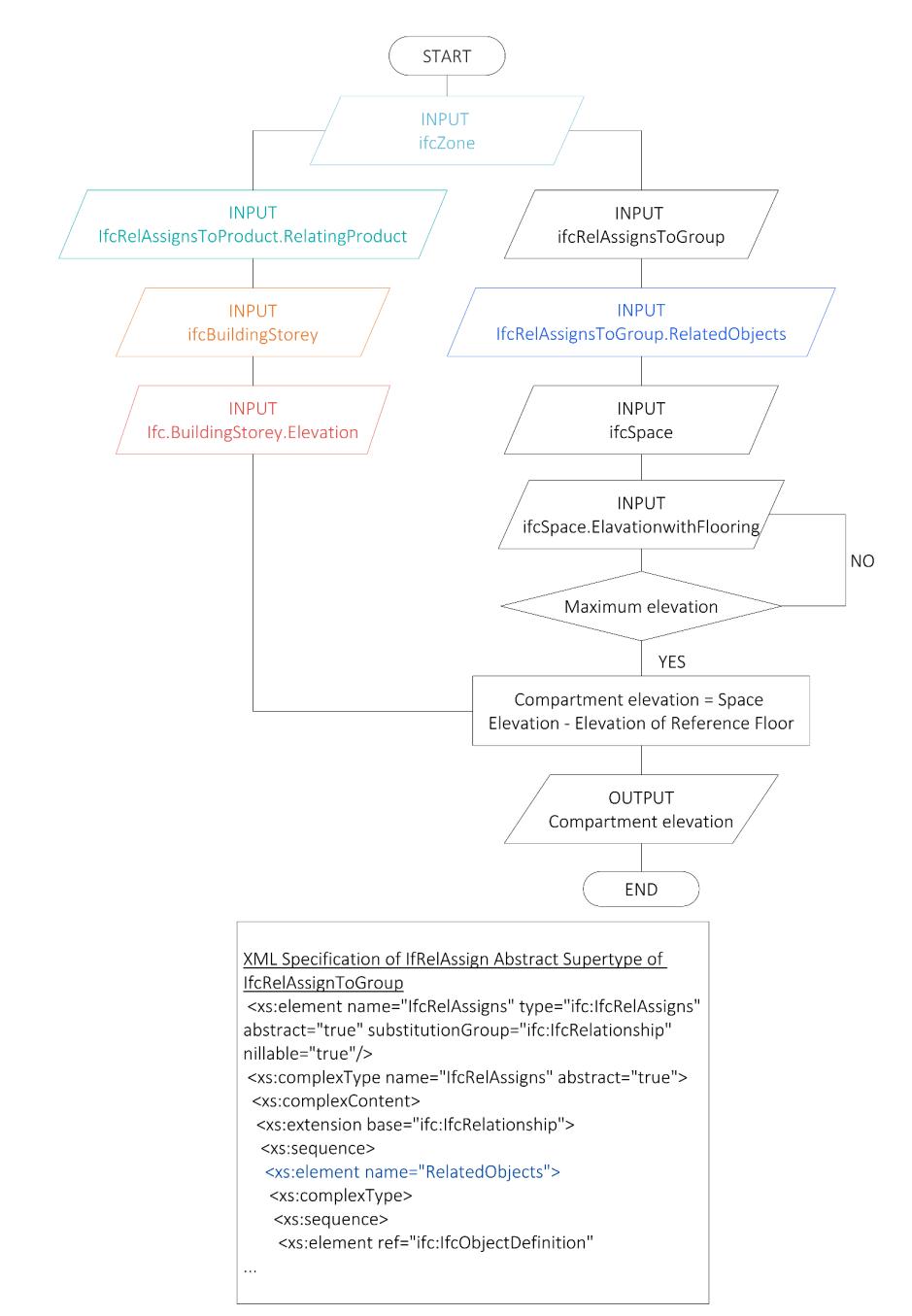
Development of an IFC data model for Fire Prevention Checking 126
Figure 83 | Algorithm Flowchart for Compartment elevation
Pset_Spacecommon and has the same name as the property defined for Zones: GrossPlannedArea (total planned gross area for space)52
The total area of the compartment is to be compared with the maximum given by norm (§ Annex I Ministerial Decree of 12 April 2019 - S.3.6.1). The limit of the norm depends on two other properties of the compartment which are Rlife risk profile (§4.2.5) and the elevation of the compartment defined above.
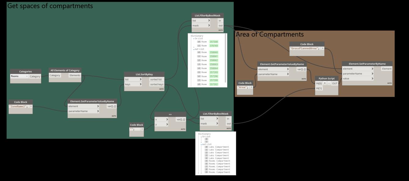
4.2.9.3 ESCAPE SYSTEM DEFINITION
The Fire Prevention Code defines the escape system as:
… a set of life-saving measures that allow occupants to reach a safe area or remain safe, independently or with assistance, before the fire leads to incapacitating conditions in the areas of activity where they are located. The evacuation system consists of safe areas, evacuation routes, exits, doors, emergency lighting, signs, etc. (Annex I Ministerial Decree of 12 April 2019 - G.1.9 comma 1)
There are four evacuation methods (Annex I Ministerial Decree of 12 April 2019 - S.4.1), Figure 85 provides for an overview of them. The downside of total evacuation is that escape routes, safe areas and any shelters in the buildings are immediately emptied, which places great demands on the capacity of the escape routes to serve all individuals simultaneously. At the same time this will increase the need for having to use a relatively large amount of the building for escape areas in the form of corridors and stairways etc. For large building, the total evacuation also leads to the
52 A differenza della classe IfcZone, la classe IfcSpace godrebbe anche del suo Quantity Set che contiene la proprietà: GrossFloorArea. Essa però èè strettamente legata alla presenza di un floor nello spazio infatti oincide con la sum of all floor areas covered by the space, It includes the area covered by elementsinside the space and excludes the area covered by wall claddings.
Analysis, mapping of Information Requirements and Building Model Preparation 127
Figure 84 | Script Dynamo. Area of Compartment
evacuation of many people who are not really in dangerous since they are far from the fire. Total evacuation used for evacuation of buildings where there is a desire to evacuate the entire building, or where it, in practice, is the only possible evacuation strategy (school for example). However, there are areas where total evacuation is usually not possible with bedridden people for example. The advantages of phase evacuation are that only a small proposition of people in the building or building section need to be evacuated at any given time, which far from imposes the same requirements to the capacity of the escape routes as the total evacuation but it needs for an organised structure in several compartments. The downside of phase evacuation, however, is that it requires that the evacuation is active by an automatic fire alarm system, which is coupled to a warning system to ensure that only the floors that the strategy says must be notified are alerted. Phase Evacuation con be used for example in parts of buildings with several floors, which heralds the storey on which it burns as well as the above and floor below. In progressive exodus each compartment must be able to contain in emergencies, in addition to its normal occupants, the number of people expected for the adjacent compartment with the highest capacity, therefore, it is important that the compartments are of adequate size (Sorensen, 2014). The difference between simultaneous and phased or progressive exodus lies mainly in the fact that in the latter two cases, the designer must provide safe areas where occupants can allocate before reaching the safe place.
Therefore, the code identifies two cases about the risk of fire: a condition in which this risk is permanently negligible and a condition in which this risk is only temporarily negligible. These aspects are translated, respectively, into the concepts of "safe place" and "temporary safe place" (Figure 86).
A safe place is a place where the risk of fire to the occupants staying or passing through it is permanently negligible; this risk relates to a fire in the activity. The public highway and any other open space safely connected to the public highway is considered a safe place (Annex I Ministerial Decree of 12 April 2019 - G.1.9 comma 2 & S.4.5.1 comma 1)
The temporary safe area is a place where the risk of fire for the occupants stationed there or passing through it is temporarily negligible; this risk relates to a fire in specified areas of the activity other than the area in question (Annex I Ministerial Decree of 12 April 2019 - G.1.9 comma 3)
Development of an IFC data model for Fire Prevention Checking 128
Therefore, a safe place can be a fire compartment (separated from other compartments by open space or smoke-proof filters) with characteristics suitable to receive and contain a predetermined number of people (static safe place) or allow orderly movement (dynamic/temporary safe place).
Another consideration to highlight is that in the first case (safe place) the risk "is related to a fire in the activity", while in the second case the said risk "is related to a fire in specified areas of the activity, other than the considered place". An example of a temporary safe place is the area of rescue assistance, a concept inherited from ISO 21542 entitled "Building construction Accessibility and usability of the built environment". (Figure 86). If in the storey of the activity the presence of occupants unable to reach independently a safe place through vertical escape routes is not occasional, the use of areas of rescue assistance could be a solution. To allow the occupants to await and receive assistance, to complete their evacuation to a safe area, the area of rescue assistance
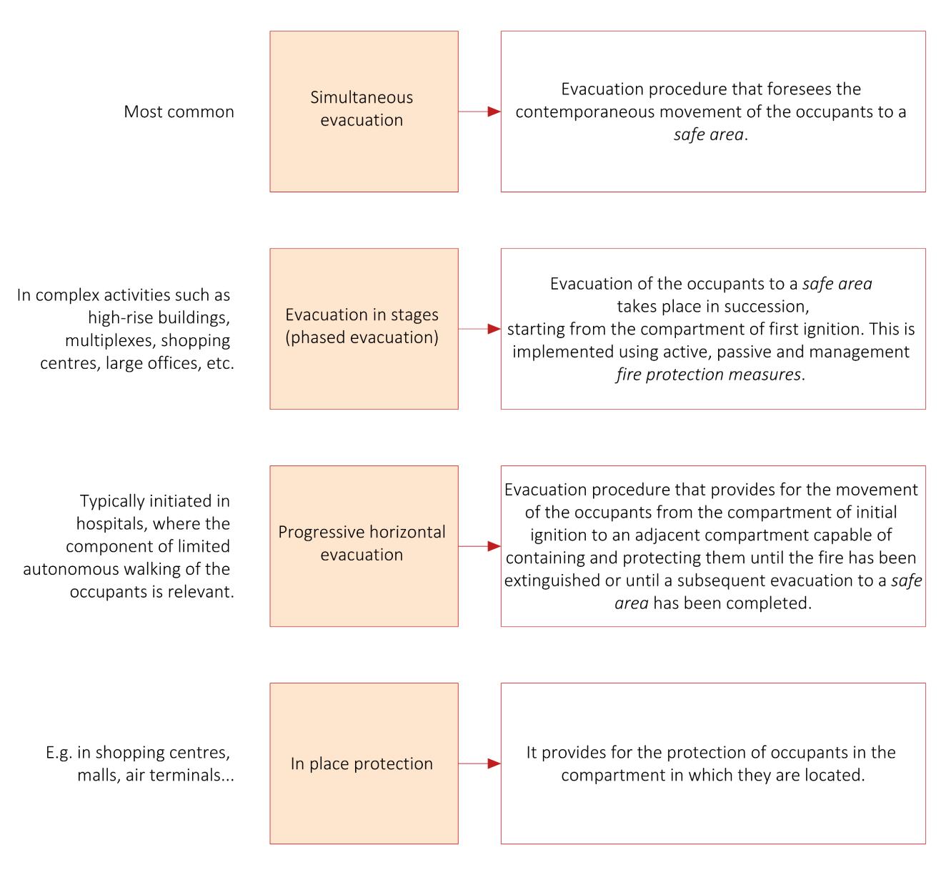
Analysis, mapping of Information Requirements and Building Model Preparation 129
Figure 85 | Evacuation methods
must be adjacent to and communicating with an escape route or be part of an escape route, without obstructing the evacuation, and must be sized to be able to accommodate all the occupants of the storey who need it, in accordance with the minimum surface area per occupant. The minimum area varies depending on whether the occupant is ambulatory, wheelchair-bound, or bedridden.
Based on the analysis of the evacuation methods it is believed that, for IFC modelling, it is useful to create two macro-groups, the first containing the three kinds of evacuation, the second for which no type of evacuation is foreseen. The creation of an ad hoc parameter that tells me which is the type of evacuation adopted can be useful but at the same time, it is considered superfluous because as well as all the other strategies analyzed there is already the PerformanceLevelEscapeRoute property contained in the user-defined Property Set Pset_FirePreventionStrategy that allows mapping for each IfcZone if it has been designed so that the occupants are safe in the place where they are (Performance level II) or if an escape zone has been provided for it (Performance level I) (Annex I Ministerial Decree of 12 April 2019 - S. 4 .2). It will, then, be the definition of the geometry and spaces of the activity that will allow the distinction between a simultaneous evacuation and a progressive or phased one. For example, to define whether a certain compartment is a temporary safe place, one can assign to the IfcZone (or IfcSpatialZone) class the FireExit boolean property of the Property Set Pset_SpaceFireSafetyRequirements (Figure 87). In this way, the compartment is mapped in the IFC model as a zone capable of accommodating occupants of an adjacent compartment where a fire has occurred. Defining this property could distinguish a progressive from a simultaneous exodus since the presence of compartments as temporary safe places is a prerogative of the progressive method of evacuation. Since no property can define whether a compartment is a temporary safe place, we have tried to fill this gap in the manner just explained.
A temporary safe space can also be an uncovered space and would be defined by creating an IfcSpace with the properties IsExternal, of Property Set Pset_SpaceCommon, and FireExit, of Property Set Pset_SpaceFireSafetyRequirements, set with the value TRUE. Instead, a area of rescue assistance could be mapped in an IFC model assuming to create an IfcSpace set with the ObjectType attribute filled with the value AreaOfRescueAssistance and with the value PARTIAL for the CompositionType53 attribute if it is part of another space belonging to the escape route like the first example in Figure 86 where the area of rescue assistance is part of the stairwell. Even for this last case, it was necessary to make assumptions with the existing dataset because the IFC standard is not yet mature to map all these requirements.
53 To date, this attribute is only fillable in an IFC model with Graphisoft Archicad 24 and not Autodesk Revit 2021.
Development of an IFC data model for Fire Prevention Checking 130
Before making an overview of the main rules required by section S.4 of the Code, it is essential to define what are the elements that make up an escape system: doors, stairs spaces such as corridors and stairwells, are the three main and on which the research has focused.
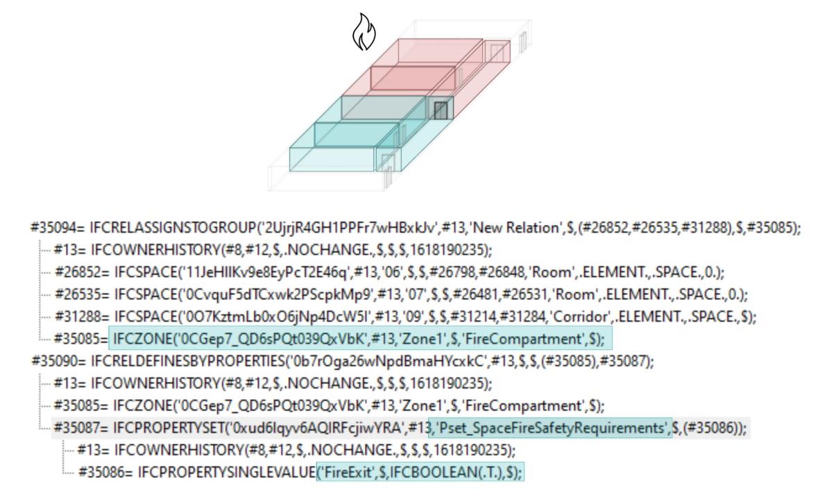
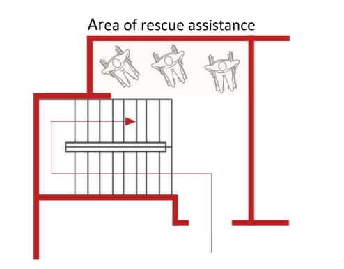
An escape route can be horizontal54 or vertical55, from each room there can be more than one escape route and when you enter a portion of an escape route that allows escape in one direction only then the portion is called a dead-end corridor (Annex
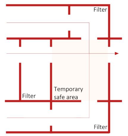
54 Horizontal evacuation route: a portion of the evacuation route at a constant height or with a slope ≤ 5 %.
55 Vertical evacuation route: a portion of the evacuation route enabling occupants to exit on varying levels with a slope > 5 %.
Analysis, mapping of Information Requirements and Building Model Preparation 131
Figure 86 | Example of an area of rescue assistance and temporary safe area (inspired: Ministerial Decree 12 April 2019)
Figure 87 | IFC mapping of a temporary safe area
–
I Ministerial Decree of 12 April 2019
S.4.8.2). In Figure 88, for example, the first and second floor are served by a single staircase which is, therefore, a dead-end corridor, the ground floor on the other hand has two possible escape routes.
Also, escape routes are distinguished according to their degree of protection and compartmentalization concerning the rest of the premises. They can be protected, smoke-proof, external or unprotected and are part of an escape system, stairs, corridors, moving walkways, ramps. Taking the example of stairs, Italian regulations do not explicitly speak of fire stairs, but this term in common language usually refers to three types of stairs, each usable as an escape route in case of need: external safety stairs, protected stairs, and smoke-proof stairs56 .
Table 25 shows the explanation of the three types of stairs that can also be extended to any other room of the escape routes (Allione, 2020). When entering an escape route with a single directionality the spaces that make up that escape route must be of the same type. So, if you enter a smoke-proof stairway all subsequent rooms must be smoke-proof.
The strategy presented below to define escape routes in an IFC model is based on assumptions that have been made considering the existing dataset. The basic idea is to use the class IfcSystem to group the spaces belonging to an escape route (through the relationship IfcRelAssignsToGroup). All spaces belonging to the system will have the boolean property FireExit set to TRUE (Figure 89). A system is an organized combination of related parts within an AEC product, composed for a common purpose or function or to provide a service. According to BuildingSMART:

A system is essentially a functionally related aggregation of products. The grouping relationship to one or several instances of IfcProduct (the system members) is handled by IfcRelAssignsToGroup. (BuildingSMART International, 2020b)
To date, this entity seems to be the most appropriate to represent escape routes as they are systems that group spaces in sequence and serve spaces, compartments, or activities of a building.
56 The regulations speak of protected staircases or smoke-proof staircases, but it is important to clarify in a logic of three-dimensional modelling that it is the stairwell that is protected or smoke-proof. Therefore, it is necessary to make a distinction between external staircases and those contained in stairwells.
Development of an IFC data model for Fire Prevention Checking 132
Figure 88 | Example of a dead-end corridor (source: Ministerial Decree 12 April 2019)
EXTERNAL STAIRS
External safety stairs cannot be used in the normal use of the building. They are the best solution when no other type of staircase can be properly installed, such as in historic buildings containing schools, hospitals, museums, and public offices. The external staircase must lead to a safe place by an external route or directly.
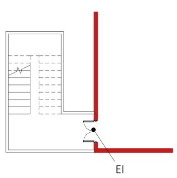
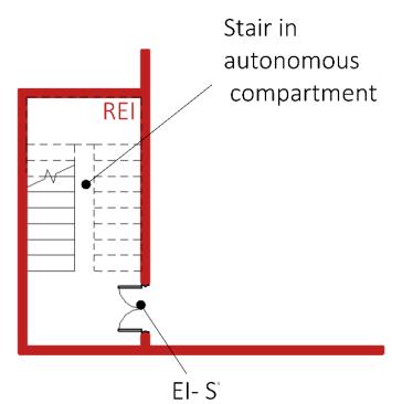
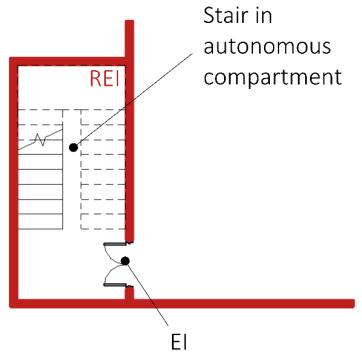
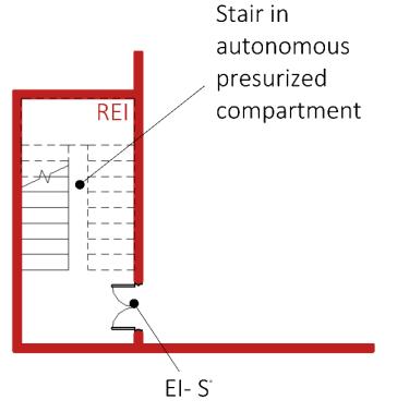
PROTECTED AND "FILTER" STAIRS
Protected staircases are built in a dedicated compartment that constitutes a fire compartment, have at least one direct access from each floor, and are equipped with REI fire doors with a self-closing device. They are also almost always used as normal access stairs. Protected stairs must lead to a safe place by a protected route or directly. Depending on the level of safety achieved, it is possible to distinguish between filter-type and fire compartmentalised escape routes. Filter-type escape routes are built into fire compartments with smoke-proof doors.
FILTER AND SMOKE-PROOF STAIRS
Finally, smoke-proof stairs are the safest and most efficient stairs because they receive constant ventilation from outside, prevent smoke from entering, and remain easily passable even during a fire. Generally, a smokeproof staircase consists of three parts:
- The actual staircase, which is built in a dedicated compartment with continuous fire-resistant walls;
- The smoke-proof filter, i.e., a hallway with adequate direct ventilation that is also functional in the event of fire;
- The compartmentalisation system guaranteed by REI fireproof doors with a self-closing device. Each smoke-proof staircase is therefore separated from the fire by two REI doors, placed respectively between the hallway system and the smoke-proof filter, and between the filter and the staircase itself. This prevents smoke and heat from entering the stairwell. As an additional safeguard, an open skylight or smoke and heat evacuator on the roof almost always provides direct ventilation to the staircase as well. The smoke-proof staircase must lead to a safe location via a smoke-proof route or directly. A smoke-proof escape route could also be built into a pressurized compartment. The pressurization system would prevent smoke from entering the compartment.
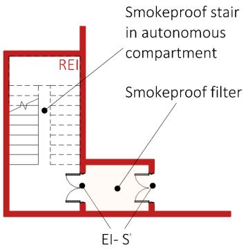
Analysis, mapping of Information Requirements and Building Model Preparation 133
Table 25 | Firefighting stairs (Annex I Ministerial Decree of 12 April 2019 - S.4.5.3)
The assumptions that can be made to define whether an escape route is protected or smoke-proof are the same as those presented in the discussion on smoke-proof compartments (Figure 73 - Figure 74 - Figure 75). What changes is that, if to define a compartment you used the class ifcZone or IfcSpatialZone, to group the rooms that are part of it, in the case of the escape routes, you are supposed to group the spaces through the class IfcSystem. However, the ObjectType parameter might help to define whether the escape route is:
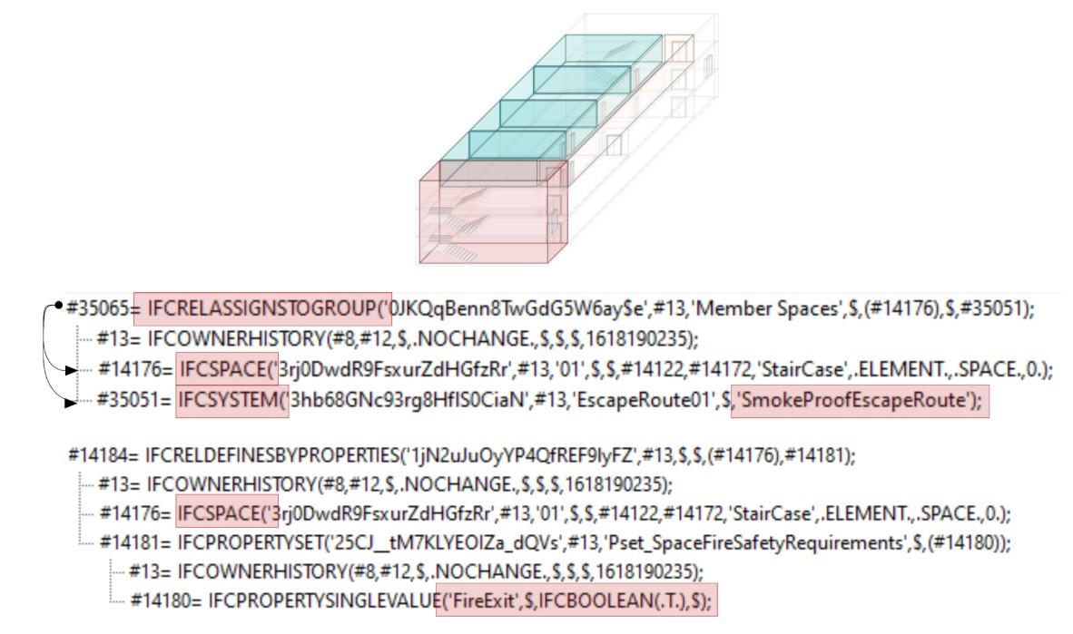
- Smoke-proof, by filling it with the value "SmokeProofEscapeRoute" (Figure 89);
- Protected, by filling it in with the value "ProtectedEscapeRoute";
- Unprotected, by filling it in with the value "UnprotectedEscapeRoute".
Figure 90 and Figure 91 show the example layouts of the possible solutions that can be found. The examples are divided according to the evacuation method. The examples shown are intended to highlight how the circulation spaces relate to the compartments. In the case of simultaneous exodus, the compartments can be connected to the escape routes using smoke-proof filters to make the escape system smoke-proof (Figure 90). The first example of simultaneous evacuation differs from the second in that, in the first example, the compartments contain only the workrooms, while in the second example the compartments also include the circulation rooms that are functional for the escape and lead to the final exit of the compartment from where the escape
Development of an IFC data model for Fire Prevention Checking 134
Figure 89 | IFC export of Escape Route
Object Ifc Entity ObjectType attribute value Unprotected escape route IfcSystem UnprotectedEscapeRoute Protected escape route IfcSystem ProtectedEscapeRoute Smoke proof escape route IfcSystem SmokeProofEscapeRoute
Table 26 | IfcZone/ifcSpatialZone ObjectType for Compartments
route is taken. The last two layouts of the simultaneous evacuation (Figure 90) propose two possible scenarios of protected escape routes. For the phased exodus, the layouts are very similar to the previous ones what changes is only that the compartments cannot be multi-storey (Annex I Ministerial Decree of 12 April 2019 - S.4.7.1). Instead, in the case of the progressive exodus (Figure 91), communication between compartments must be provided. To evacuate from the compartment where the fire may break out, the occupants of the compartment may cross over to another compartment and then enter the escape system. In the case in the figure, compartment 2 is a temporary safe place for compartment 1 which is where the fire breaks out, but in the same way compartment, 1 can be a temporary safe place for compartment 2 if the fire breaks out in compartment 2. As in the previous case, each compartment must have two possible exit routes, if these are not smoke-proof, but if the exit routes are smoke-proof, only one can be foreseen. The two main relationships that connect the escape routes to the compartments are IfcRelSpaceBoundary and IfcRelAssignsToGroup. The first allows mapping the connection between the gates, Ifcdoor entities, and the filters, or the rooms of a compartment or escape route. The second connects the spaces with the compartment. Therefore, to identify the escape route we focus on space objects and their topological connectivity through doors. Although there is this indirect connection between the compartments and the escape routes through the IfcDoor entities, to map which escape routes serve a particular compartment, it would be necessary to define further relations between the IfcSystem representing the escape route, the IfcSpace representing the filter, if present, and the IfcZone representing the compartment.
To find a solution to this problem, it is necessary to make two distinctions. In the first two examples in Figure 90 where the filter separates the compartment from the escape route, the relationships between these three entities can only be expressed through the IfcRelAssignsToProduct relationship. The objectified relationship IfcRelAssignsToProduct handles the assignment of objects (subtypes of IfcObject) to a product (subtypes of IfcProduct). IfcZone and IfcSystem are subtypes of IfcObjects and can be referred to the IfcSpace being a subtype of IfcProduct. In this case, the filter would become the IFC object connecting compartments and escape routes. You could also use the IfcRelServicesBuildings relationship, but it would not be semantically correct. It is used to define the spatial element which is serviced by the system. It is not correct to relate a system to a filter with this class since the escape route system serves the spaces or compartments and not the filter which is designed to make the escape route smoke-proof. The same applies to the compartment represented by the IfcZone which does not need the filter which is built to separate the compartment from the escape routes. In the second two examples in Figure 90 where the escape route is only protected it would not be possible to use this relationship due to the lack of the filter that connects the escape system to the compartment. The situation changes if the IfcSpatialZone class is used for the compartments. In that case, the relationship IfcRelServicesBuildings (which will be replaced by the relationship IfcRelReferencedInSpatialStructure with IFC4.3) allows relating the IfcSystem entity (Escape Route) to the IfcSpatialZone (Compartment) without the need to relate it to the IfcSpace (Filter). Therefore, in the absence of a filter, the Escape Route and the Compartment would still be connected (Figure 92).
Analysis, mapping of Information Requirements and Building Model Preparation 135
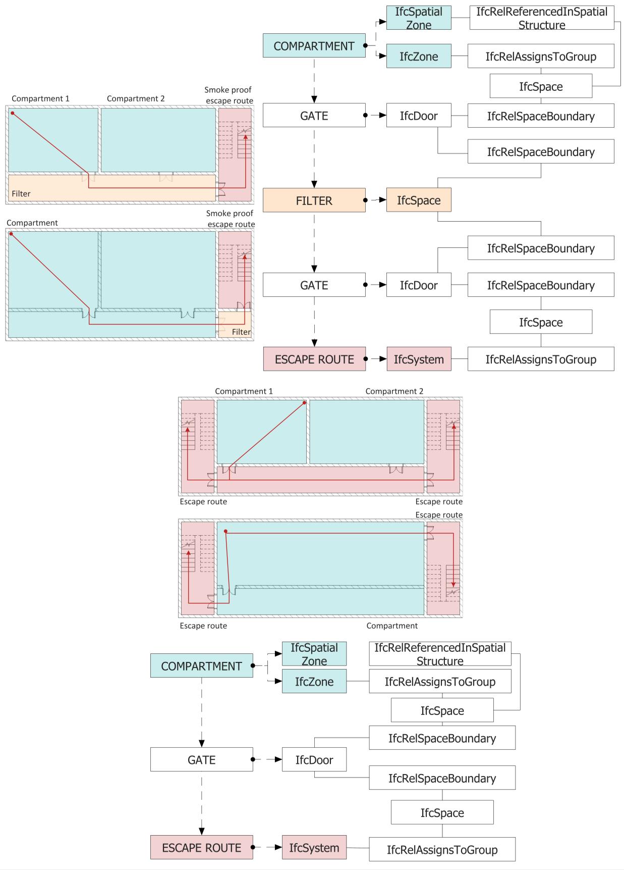
Development of an IFC data model for Fire Prevention Checking 136
Figure 90 | Simultaneous evacuation: example layouts for compartmentalisation & escape routes with IFC entities and relationship definition
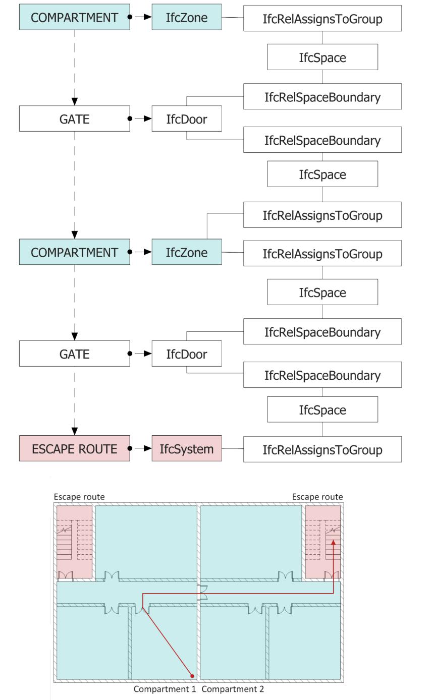
Analysis, mapping of Information Requirements and Building Model Preparation 137
Figure 91 | Progressive horizontal evacuation: example layouts for compartmentalisation & escape routes with IFC entities and relationship definition
The cases described above assume that escape routes serve activities or compartments. Actually, an escape route can also serve spaces without necessarily putting them into compartments (Figure 93). Consider the case of a school (Annex I Ministerial Decree of 12 April 2019 - V.7), it is not necessary to compartmentalize the rooms intended for teaching activities if they do not have a high fire risk. In that case, therefore, the escape routes are not protected, or smoke-proof and no compartments are needed but simply rooms (Figure 93). At that point stairs and corridors that make up the escape routes could be grouped in an ifcSystem that would have as ObjectType the value "UnProtectedEscapeRoute". When entering a protected or smoke-proof escape route that escapes route is unidirectional and leads directly to a safe location. The problem associated with the latter scenario is that often a corridor that several classrooms face can lead to multiple exits but also multiple stairs. In that case, the corridor should be part of two different systems. To define the final exit associated with each classroom, the IfcRelServicesBuildings relationship could be used once again (which will be replaced by the IfcRelReferencedInSpatialStructure relationship with IFC4.3). It allows connecting each IfcSpace to an escape route system to define which spaces are served by it. In that case, even if the unprotected corridor overlooked by the classrooms is shared by several escape routes, the IFC model contains the relationship between the IfcSystem and the IfcSpace. (Figure 94).
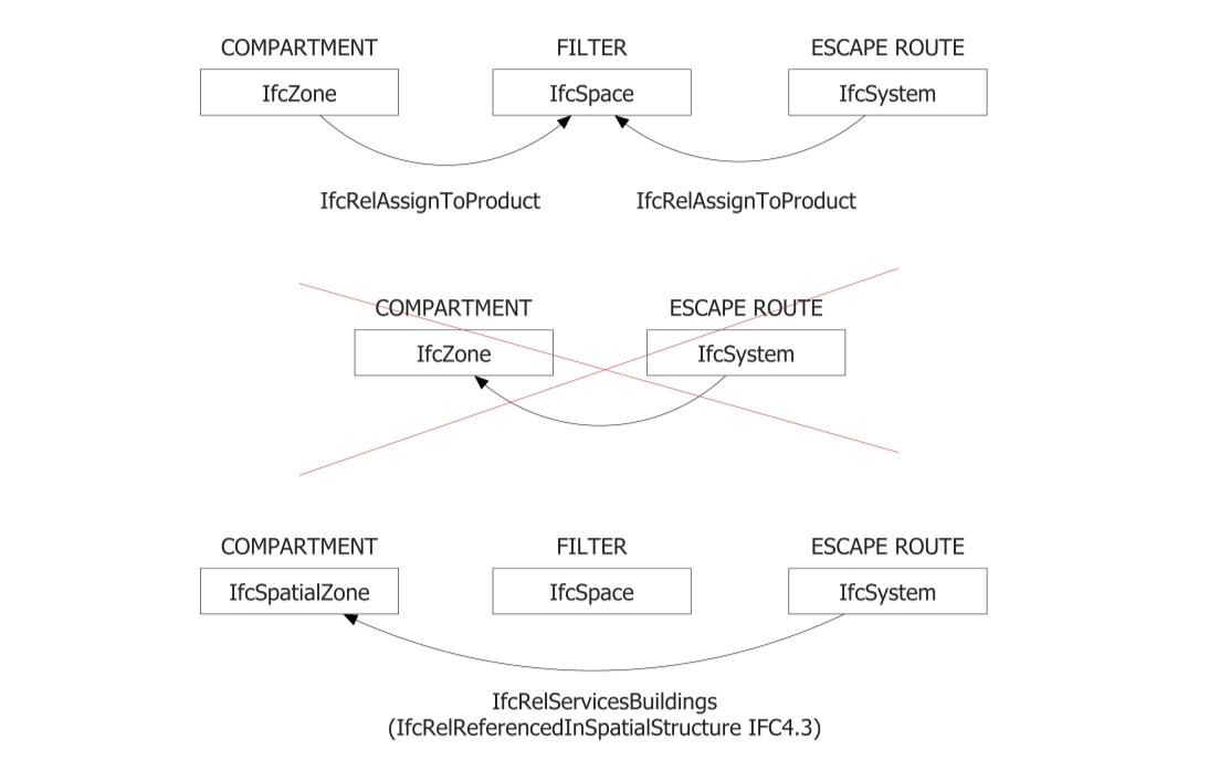
Development of an IFC data model for Fire Prevention Checking 138
Figure 92 | Compartment and Escape Route relationship
Finally, the escape routes could also be external. The creation of an IfcSystem, in this case, is insignificant, the scale will simply be recognized by the boolean properties:
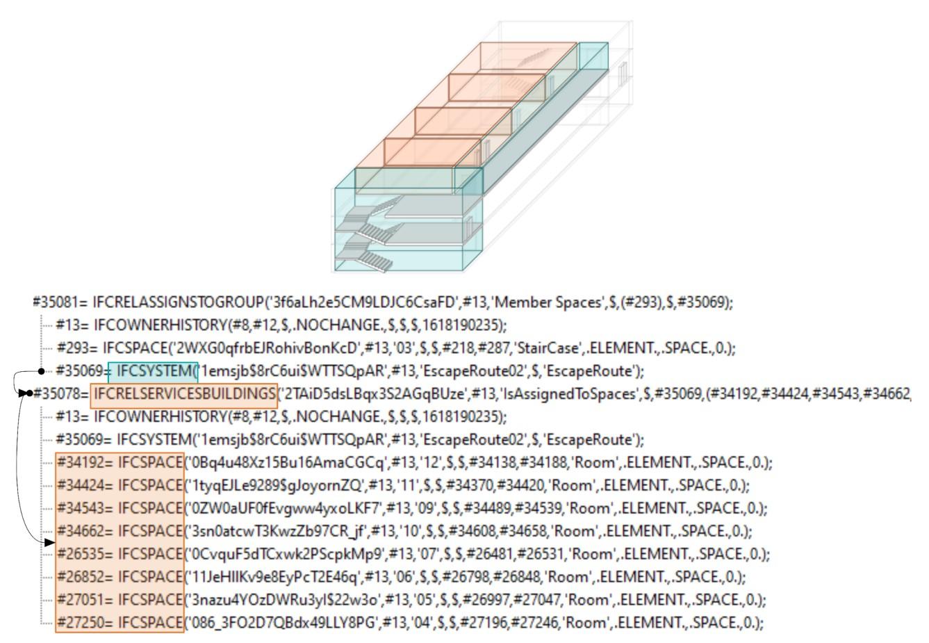
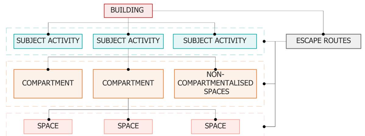
Pset_StairCommon.FireExit
Pset_StairCommon.IsExternal
Analysis, mapping of Information Requirements and Building Model Preparation 139
Figure 93 | Connection between Escape Routes and Activities, Compartments and Spaces
Figure 94 | IFC Mapping of unprotected escape route
The last consideration concerns the circulation spaces that are located within a compartment. The grouping of these within the IfcSystem entity representing an escape route could be misleading, firstly because these spaces have a lower degree of protection than the spaces of an escape route as they are not separated from the compartments. Moreover, the spaces of circulation could lead to two different escape routes and therefore they would have to take part at the same time of two different IfcSystem. To indicate whether a space is designed to serve as an exit space, for fire escape purposes we will use the property FireExit of Pset_SpaceFireSafetyRequirements. In conclusion the class IfcSystem groups spaces with the same degree of protection. The creation of Systems that group spaces with the same degree of protection is fundamental to define the maximum length of the entire escape route. (§4.2.9.4).
After the entrance GATE to an escape route, there is generally a STAIRCASE or a CORRIDOR (Figure 95). In the case of a space STAIRCASE, the IfcStair entity relates to the space with the IfcRelContainedInSpatialStructure relationship (Figure 95). The example was obtained through the IFC exporter of Graphisoft Archicad 24. In Autodesk Revit 2021, it was not possible to relate Stair to Space. It is only related to the IfcBuildingstorey entity in which it is located.
Another important element of the escape route is the door, IfcDoors must have certain characteristics to be considered as doors along escape routes. In general, doors installed along escape routes can be divided into three types:
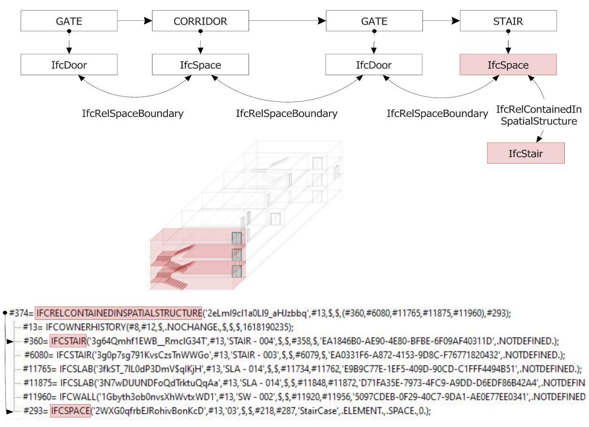
Development of an IFC data model for Fire Prevention Checking 140
Figure 95 | IfcSystem and connectivity with IfcDoor, IfcStair and IfcSpace entities
Doors leading to an escape route;
Doors between the spaces of an escape route, such as those between a corridor and a stairwell;
Doors leading to another compartment (only in the case of the progressive exodus); Doors leading to a safe place.
All four types will have the FireExit property of the Property Set Pset_SpaceFireRequirements set to TRUE. The first ones are different from the second ones because the IfcDoor entity will be related through the IfcRelSpaceBoundary relationship, in the first case with only one IfcSpace that belongs to the IfcSystem, in the second case with two IfcSpaces assign to the IfcSystem entity. In case the exit system is protected the entrance door to the exit system is also the exit door from the compartment. Therefore, it will be related to two ifcSpaces, one belonging to the IfcSystem and one belonging to an IfcZone. In the case where the escape route is smoke proof, then the second space with which the door is related belongs neither to a zone nor to a system but will be related to the space filter. In the third case, the entity IfcDoor will be related to two spaces belonging to different IfcZone while in the last case the boolean property IsExternal of the Pset_DoorCommon compiled with the TRUE value makes possible the distinction of this last one from all the other typologies. In this last case, the relation that binds the class ifcDoor with the class ifcBuildingStorey makes it possible to define which are the exit storey towards the safe place of the building
4.2.9.4 DATA FOR ESCAPE SYSTEM DESIGN
In the following, the limitations, and conditions for the use of compliant escape route solutions are discussed to identify what information a fire protection designer should assign to the components of the escape system for code checking purposes.
In the code, compliant solutions are only given for performance level I which requires occupants to reach a safe place before the fire causes incapacitating conditions in the areas of the activity crossed during the escape. For performance level II, which requires occupants to be protected at the location, no compliant solutions are given, the following alternative solutions are required.
The escape system must be designed in accordance with several semi-performance parameters, mainly governed by the Rlife risk profile (§4.2.6) and crowding
The maximum crowd size in each room is determined by multiplying the occupant density (Pset_SpaceOccupancyRequirements.AreaPerOccupant) by the gross surface area of the room in question (Pset_SpaceCommon.GrossPlannedArea). The result will be set as the value of the parameter OccupancyNumberPeak of the Pset_SpaceOccupancyRequirements. In this Property Set assignable both to the class IfcSpace and to IfcZone and IfcSpatialZone there are two properties related to the number of occupants (OccupancyNumberPeak and OccupancyNumber) but since the Code refers to the maximum crowding the more correct property is OccupancyNumberPeak.
Analysis, mapping of Information Requirements and Building Model Preparation 141
In activities such as hospitals or meeting rooms where the density of crowding is less significant, the calculation of the total number of people is not made based on the available area but through other criteria such as, for example, the number of seats or the numbers of beds by adding the number of employees 57. Once the crowding of each compartment served by an exit route has been defined, the crowding of the actual exit route must be calculated. In practice, it will be given by the sum of the occupants coming from each room served by the same escape route.
The parameters required by the regulations include, for example, the minimum number of independent escape routes and exits, escape lengths and dead-end corridors, calculation of minimum width of horizontal and vertical escape routes, verification of redundancy of horizontal and vertical escape routes, the minimum number of independent horizontal and vertical escape routes, calculation of minimum width of final exits and management of escape in the presence of disabled occupants. The following is a description of a series of considerations that have been made to map the information regarding the length of escape routes and dead-end corridors in an IFC model to then proceed to the comparison with the maximum values provided by the regulations.
The prescriptive method involves two types of verifications related to the length of the escape routes. The first consists of verifying the maximum length of dead-end corridors (Lcc) and the maximum omissible length of a dead-end corridor (Annex I Ministerial Decree of 12 April 2019S.4.8.2). The second is to verify that the total length of an exit route (Les) is less than the maximum limit established by the Code (Annex I Ministerial Decree of 12 April 2019 - S.4.8.3). The first one refers to the worst of the Rlife risk profiles of the compartments served by the blind corridor and to the crowding of the same. On the other hand, the second refers only to the Rlife risk profiles of the compartments served by the blind corridor
The regulations state that the permissible portion of an escape route varies according to the degree of protection of the same route (Table 28). Therefore, if the escape route is protected, it is possible to omit a smaller portion than if it is smoke-proof, just as if it is unprotected, the permissible length is even smaller. Only in two cases, the omissible portion of the dead-end corridor is unlimited: if the escape route is outdoors or if it is smoke-proof and the rooms served are served by fire detection and alarm systems (FDAS).
For example, in the case in Figure 96.a the storeys +1 and +2 are served by a single stair (dead-end corridor). According to one of the possibilities of Table 28, if the only stairs have filter characteristics and a length of ≤ 45 m (Lom), it can be omitted from the verifications of the maximum
57 Some criteria can be found in Table S.4-13 of the Fire Prevention Code.
Development of an IFC data model for Fire Prevention Checking 142
Name Type Description OccupancyNumber IfcCountMeasure Number of people required for the activity assigned to this space. OccupancyNumberPeak IfcCountMeasure Maximal number of people required for the activity assigned to this space in peak time.
Table 27 | Pset_SpaceOccupancyRequirements
length of the dead-end corridor. If the system is unprotected, only a maximum portion of 15 m can be omitted and only if the unprotected spaces lead directly to the final exit. This means that the portion of the escape route inside the compartment Figure 96.b cannot be omitted because it is not protected as it is part of the compartment itself and does not lead directly to a safe place but a filter staircase. Instead, in the last example (Figure 96.c), the escape route that crosses the entrance is not omittable
a. Conditions for dead-end corridors
b.
c. Conditions for omitting a section of a dead-end corridor
The settings (areas) served must have an occupant density of ≤ 0.4 p/m2 and, if open to the public, a total of ≤ 300 occupants, otherwise a total crowd size of ≤ 500 occupants. In these settings (spaces), the presence of significant quantities of hazardous substances or mixtures, or of hazardous works with a fire risk, is not permitted. Each room in which occupants may sleep must be protected and have doors of at least E 30-Sa. [1] If composed of several continuous sections with different characteristics, the max omitted length Lom is calculated as the weighted average, without taking into account the sections with an unlimited Lom. The protection characteristics must increase in the direction of the evacuation. [2] The areas served are equipped with a performance level III fire detection and alarm system (chapter S.7.) and have a performance level II fire safety management plan (chapter S.5).
Analysis, mapping of Information Requirements and Building Model Preparation 143
Table 28 | Escape Routes length checking
Rlife Max crowd size Max length Lcc Rlife Max crowd size Max length Lcc A1 ≤ 100 occupants ≤ 45 m B1, E1 ≤ 50 occupants ≤ 25 m A2 ≤ 30 m B2, E2 ≤ 20 m A3 ≤ 15 m B3, E3 ≤ 15 m A4 ≤ 50 occupants ≤ 10 m Cii1, Ciii1 ≤ 20 m D1 ≤ 20 m Cii2, Ciii2 ≤ 15 m D2 ≤ 15 m Cii3, Ciii3 ≤ 10 m
Rlife Max travel distance Les Rlife Max travel distance Les A1 ≤ 70 m B1, E1 ≤ 60 m A2 ≤ 60 m B2, E2 ≤ 50 m A3 ≤ 45 m B3, E3 ≤ 40 m A4 ≤ 30 m Cii1, Ciii1 ≤ 40 m D1 ≤ 30 m Cii2, Ciii2 ≤ 30 m D2 ≤ 20 m Cii3, Ciii3 ≤ 20 m
Maximum travel distances
Characteristics of the omitted section Max omitted length Lom [1] Additional provisions With filter characteristics ≤ 45 m None ≤ 90 m [2] With filter and smokeproof characteristics ≤ 120 m None Unlimited [2] Also unprotected, ending directly at the fire exit or in a place of ultimate safety ≤ 15 m None From the fire exit to the place of ultimate safety, in an external escape route. Unlimited None
Based on these considerations, separating the parts of the escape routes according to their degree of protection is essential. This is fully in line with the assumptions made in the previous paragraph about mapping Escape Routes in an IFC model. As shown in Figure 90 the IfcSystem entity corresponds to the grouping of spaces that have the same degree of protection.
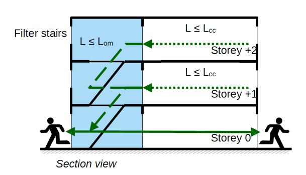
To date, the IFC data model does not allow mapping the length of the escape routes in a model, so it is deemed necessary to define new properties. The research initially focused on defining what could be the IFC entity to associate the properties to.
Associating the property total escape length to the exit door of a street is necessary but not sufficient to frame the problem of escape lengths presented in the Italian Fire Prevention Code. Below are some considerations that have been made to formulate assumptions on how to address the problem in IFC.
Assuming, for example, an emergency staircase serving several floors of a building, the conformation of the building may require that the distance to the emergency staircase is greater for the second floor than for the higher floors. Therefore, it is essential to define for each floor the maximum distance from the staircase to understand which length, when added to the length of the staircase, will tell me the maximum distance an occupant must travel to reach the exit door associated with that escape system.
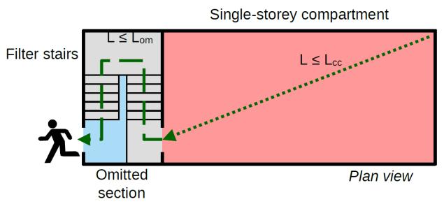
Another consideration is if you have a corridor that can lead to two different escape routes. In this case, it is necessary to make a recursive analysis between all the staircases facing the corridor and the doors to the rooms leading to the corridor At that point, the staircase that is the least distance from the room would be associated with it.
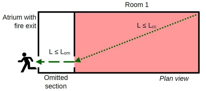
Development of an IFC data model for Fire Prevention Checking 144
a.
b.
c.
Figure 96 | Example of omitting a section of a dead-end corridor
A further concept to highlight concerns those rooms which, due to their size and crowding, are served by several exits. In this case, each door will be associated with a maximum distance inside the room from the door itself.
Based on the above considerations, it seems logical to define partial lengths of escape routes corresponding to the distance between two successive emergency exits. The IFC class that is best suited to be defined by these properties is the IfcDoor class.
Initially, we immediately ruled out associating such properties to the IfcSpace class for two main reasons:
if a corridor is associated with more than one staircase, defining a length property for the corridor entity would not allow defining for each staircase what is the length that the staircase brings from the previous section of the escape route;
If an escape route is unprotected and therefore there is probably no door separating, for example, the corridor of a floor from the staircase, the definition of the length of the corridor to reach the staircase is of little importance, in fact, the purpose of escape routes is to define the lengths to reach safe places, whether temporary or final.
It was thought to assign two properties to the IfcDoor class:
- "PreviousExitLength", which defines what is the length of the escape route preceding that door, so what is the distance to reach that door.
- "NextExitLength" which defines what is the distance to the next emergency exit or in the case of a final exit door the distance to the safe place (be it the public road or open space).
The value of the first of the two parameters filled in for a final exit door is the one that needs to be compared to the maximum length allowed by the Code.
Instead, checking the length of the dead-end corridor may require additional property. The distance between two successive safety doors or the distance before a door is not relevant in deadend corridor logic. A dead-end corridor could be composed of one or more spaces with the same degree of protection. As seen in the previous chapter, the definition of an IfcSystem that groups together spaces with similar characteristics have the function of defining a dead-end corridor. When the occupants reach it, the direction they must follow to evacuate the building is unique. At that point, in a prescriptive design perspective, you could define a property for the IfcSystem entity to map in an IFC model the length of the dead-end corridor (“DeadEndCorridorLength”) and the maximum omitted length (“OmittedLength”). At that point, however, the value of the end length associated with the exit door from the building to the safe location should be deprecated by this length.
The introduced properties have been grouped under the user defined Property Set Pset_EvacuationLength (Figure 97).
Analysis, mapping of Information Requirements and Building Model Preparation 145
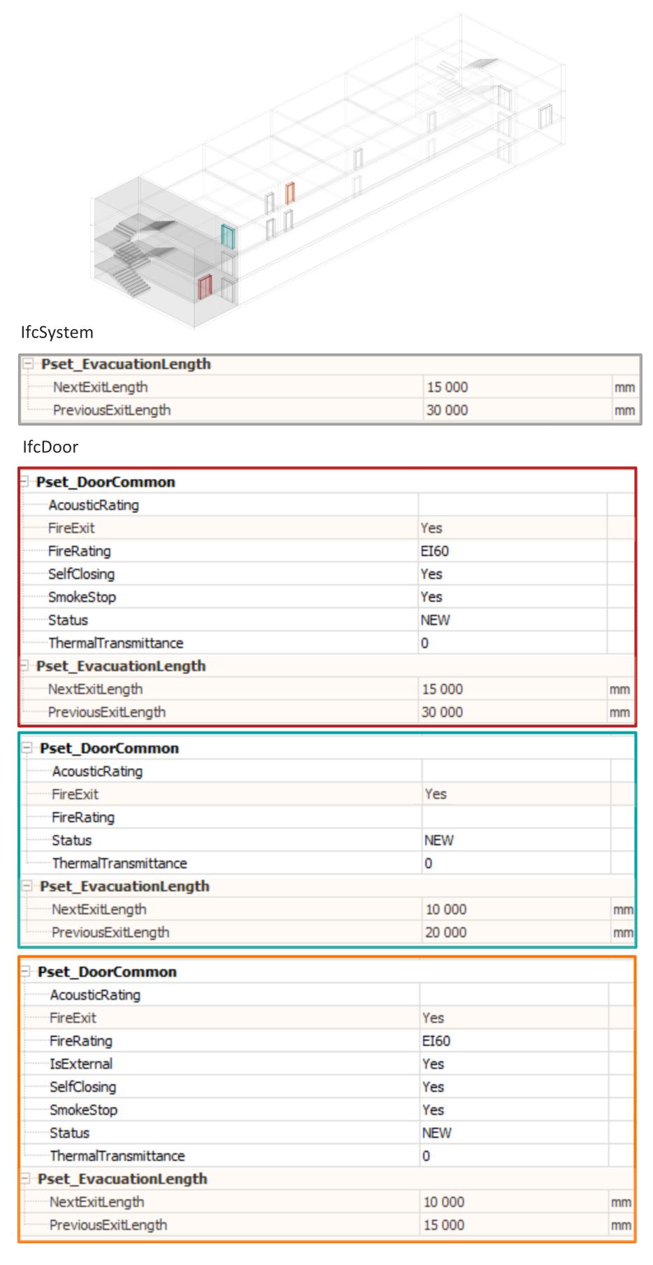
Development of an IFC data model for Fire Prevention Checking 146
Figure 97 | User defined property set for escape route length
In addition to the definition of the mentioned properties, it is logical to make sure that these properties are calculated and not manually compiled by the designer. In this sense, the definition of an algorithm able to do this would allow that, in front of a modification of the project, the data are updated automatically.
To be able to implement this algorithm it is necessary to make use of two fundamental concepts of the IFC dataset: Product Local Placement and Product Shape Representation. The first one is used to identify the position in the model of the doors, the second one is used to obtain the coordinates of the spaces on one side and the geometric representation of elements such as walls, furniture, or any common object that is an obstacle for the occupants to reach the nearest exit door.
Furthermore, in a fire safety logic, spaces should be distinguished between those that host the activities of a building (WORKSPACE) and those that belong to the circulation and escape routes. This distinction should be made because depending on the type of room, the calculation of the internal escape length will take into account different aspects. The calculation of the length of a route can be divided into two steps:
The exit from the room
The length of the routes into the circulation spaces
In the first case, one should calculate the maximum distance from the coordinates of vertices of the space to the coordinates of the door, in the second case the distance between the doors. Therefore, in addition to distinguishing through the ObjectType parameter the rooms from the circulation spaces, it would be essential to define which doors serve or serve as an exit in the case of fire using the Boolean property FireExit of Property Set Pset_DoorCommon.
Product Local Placement
Geometric modeling in the IFC data model is strongly oriented around the use of a local coordinate system. As such the corners of a wall object, for example, are not specified globally but in relation to the coordinate system of the respective story. The story’s coordinates are, in turn, modelled in relation to the coordinate system of the building, and so on. The IfcLocalPlacement allows that an IfcProduct can be placed within the local coordinate system of the object placement of another IfcProduct, which is referenced by the attribute PlacementRelTo (Borrmann et al., 2018) The subtype of the abstract class IfcProduct can be placed in 3D space relative to where they are contained (Figure 98) This means that a placement follows aggregation and containment relationships as follows:
At the outermost level, a site is globally positioned according to latitude, longitude, and elevation;
For spatial structures, positioning is relative to aggregation. For example, a site may aggregate multiple buildings, each building may aggregate multiple building storeys, and each building storey may aggregate multiple spaces; For building elements, positioning is relative to the containing spatial structure. For example, a building storey may contain slabs, walls, columns, and beams;
Analysis, mapping of Information Requirements and Building Model Preparation 147
For aggregated parts, positioning is relative to aggregation. For example, a staircase may aggregate one or more stair flights;
For feature elements, positioning is relative to the affected building element. For example, an opening element is positioned relative to the wall it voids, which in turn is positioned relative to a building storey;
For fillings, positioning is relative to the filled opening. For example, a door is positioned relative to an opening which in turn is positioned relative to a wall.
The second attribute of the IfcLocalPlacement is RelativePlacement, which refers to an IfcAxis2Placement object that defines the transformation between the parent coordinate system and the embedded local coordinate system. This transformation can be either in 2D (IfcAxis2Placement2D) or 3D (IfcAxis2Placement3D). Figure 99 shows how IfcAxis2Placement3D works. The location of the origin of the local coordinate system in relation to the parent coordinate system is defined using the Location attribute. Any rotation of the local coordinate system is specified by two vectors: The Axis vector defines the direction of the local z-axis while the RefDirection vector defines the direction of the local x-axis. Both vectors must be perpendicular to each other (Borrmann et al., 2018)
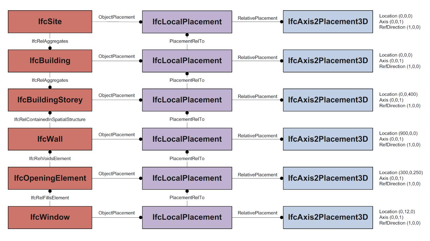
Development of an IFC data model for Fire Prevention Checking 148
Figure 98 | Relationship between LocalPlacement and aggregation hierarchy of the building object (source: Borrmann et al., 2018)
Product Shape Rappresentation
Every real object that can be described through an IFC entity is derived from the IfcProduct entity. The geometric description of the elements belonging to the IfcProduct entity is made possible by the implementation of special entities allowing the description of two or three-dimensional elements in space. The IFC data model makes a strict division between the semantic structure and geometric description. The abstract entity that contains all possible representations of elements is called IfcProductRepresentation. A product can have zero, one, or many geometric representations, and a single geometric. Two fundamental and distinct entities enable geometric representation:
IfcProductDefinitionShape: is the representation entity referring directly to IfcProduct, it allows a name and a description to be given.
IfcShapeRepresentation: is the entity that allows managing the representations and includes within it all the entities useful for the geometric description of two- and threedimensional elements. The position of objects is defined according to what is defined in IfcRepresentationContext.
Observing the hierarchy graph, particular attention must be paid to the fields RepresentationIdentifier and RepresentationType; the first indicates the type of element to be represented, while the second specifies the representation method used for the geometric description. The use of these entities makes it possible to manage all the solid and plane representations defined by the IFC format. The main values that the RepresentationIdentifier field can assume are: Box: Bounding box as simplified 3D box geometry of an element;
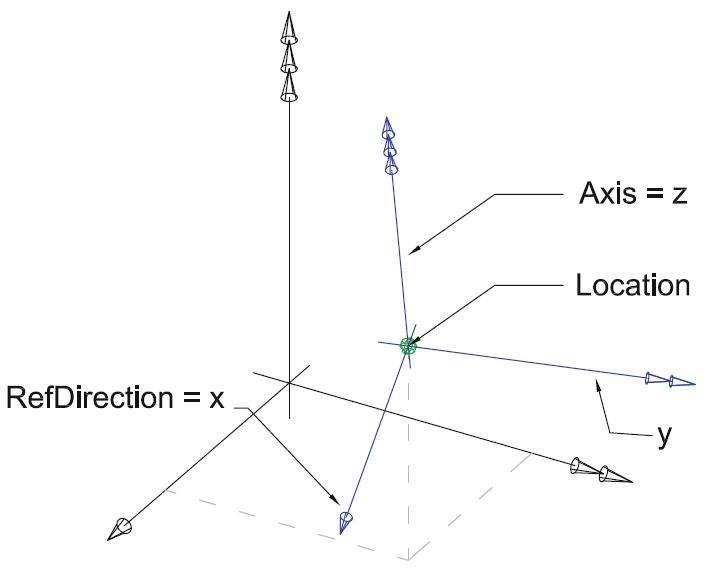
FootPrint: 2D Foot print, or double line, representation of an element, projected to ground view;
Body: 3D Body representation, e.g. as wireframe, surface, or solid model, of an element;
Surface: 3D Surface representation, e.g. of an analytical surface, of an elementplane)
While the main values of the RepresentationType field may be:
Analysis, mapping of Information Requirements and Building Model Preparation 149
Figure 99 | The definition of the IfcAxis2Placement3D within the three-dimensional coordinate system (source: Borrmann et al., 2018)
Point: Represents a point in the plane or space; curves: indicates a two-dimensional or three-dimensional curve;
Surface: Used to represent a curve in space;
GeometricSet: points, curves, surfaces (two o three-dimensional);
SolidModel: Groups solid representation methods.
For the calculation of escape routes, what counts is the plan definition of the space. Therefore, including the two-dimensional representation of objects in an IFC model could be useful for obtaining the vertices of a space. The definition refers to the absolute reference system, which means that to define the distance between the doors (whose position in space is obtained through the entity IfcObjectPlacement) and these points in space, the coordinates of the doors should be converted automatically from the relative system of the entity IfcOpeningElement in which they are inserted to the absolute system of the project.
If the compliant solution is too restrictive and/or too costly to retrofit, the regulations provide an alternative route to the prescriptive one, and Fire Safety Engineering takes it. This methodology allows the exact calculation of the time required for occupants to escape by modelling the building as a whole and entering the maximum crowding and then comparing the required safe escape time (RSET) with the time available from the most relevant fire scenarios (ASET). Typically, this translates into possibilities to increase room crowding, regulate situations with too long blind corridors and/or not enough escape routes. As well as doors that are too narrow or cannot be opened in the direction of escape (Battistini, 2018). From this, it can be seen that information on the geometry of the escape routes, and the characteristics of the escape routes are crucial. From a prescriptive perspective, information such as the length of the escape routes from the compartment will be compared with the maximum required by the regulations. From a Fire Safety Engineering (FSE) perspective, the geometry of escape routes will be used to demonstrate that escape is still possible using escape or smoke and fire simulations.
4.3. DRAFT OF THE INFORMATION DELIVERY MANUAL
In the field of fire safety, communication between the stakeholders involved in the various disciplines and at different stages is of primary importance given the multiplicity of Code requirements for the definition of a fire prevention project. In the previous chapter, some of the requirements were described and translated through the IFC standard. However, for the extraction of fire prevention information from the IFC database and the exchange of information to be standardised, it is necessary to define an Information Delivery Manual (IDM). In the following paragraphs, we intend to provide a draft of IDM following the steps described in paragraph §2.3.1
4.3.1. PROCESS MAP
he first step is to define and represent information flows through the Process Map (PM). The purpose of the Process Map is to describe the flow of activities of the fire prevention design, the roles played by each actor involved, and the information used or created by each of them. Figure 100
150
shows the main components of it. The process model uses rows to identify the actors involved in the exchange while the columns show project phases. In the cells of the rows, it is possible to represent activities as white rectangles and the data to be exchanged is shown as corner folded blocks. As presented on the very left side of the process map, the following process map is focusing on these main actors in the fire safety design:
Activity Manager, who is the actor in charge of fire prevention obligations. He must provide the fire safety professional with information about fire hazards and all other input data about the activity necessary for fire risk assessment. He could also, jointly with the Fire Safety Designer, assess the fire risk of the activity and define the fire strategy. Besides, he is the one who must send to the Fire Authority "Certified segnalation of activity beginning" (SCIA - Segnalazione Certificata di Inizio Attività).
Fire Safety Professional should evaluate the fire risk, assign fire risk profiles, decide the performance level and the fire prevention strategies according to the input data about the activity provided by the manager. He should provide this information to the design teams to start the design phase. After he must validate each design project of the teams and coordinate them ensuring that the objective of fire safety decided at the beginning are respected.
Design Teams (Architect, Structural Engineer, and MEP Engineer) who must collaborate with the Fire Safety Professional in the fire prevention design. They must provide the information of their discipline to the fire safety professional so that he could check that the fire safety requirements are verified.
Fire Brigade Authority, who should receive the project and verify the compliance of the project with the requirements of the Fire Prevention Code giving a positive or negative judgment.
The process model helps in showing the functional requirements and describes how the information exchange should work between the main actors listed above. The key activities in this process are explained below.
1.1.Activity Information Definition: activity manager defines the fire hazards and all other input data about the activity necessary for fire risk assessment.
1.2.Safety Objectives Definition: the first phase of the preliminary analysis is the fundamental step for the subsequent quantification of the effects of the fire. In this phase, the conditions most representative of the risk must be identified and the safety objectives to be pursued must be set.
1.3.Fire Risk Assessment & Risk Profile Definition: this phase consists of the identification of fire hazards (e.g., easily combustible, and flammable substances, ignition sources and heat sources, situations that may result in the easy spread of fire, identification of workers and other persons in the workplace who are exposed to fire risks) and according to them the Fire Safety Professional should define the risks profiles for the activities.
Draft of the Information Delivery Manual 151
1.4.Performance Level Assignment: the fire safety professional assigns performance levels for the various fire prevention measures according to the fire risk assessment of the activity and identifies the design solutions that guarantee the achievement of the assigned performance levels.
1.5.Fire Prevention Design: the fire safety professional applies the prescriptive requirements imposed by the Code, or he proceeds with advanced analyses of the project to verify that the life protection and property protection requirements are still complied with. This step is part of an iterative process consisting of design and review cycles during which the designers and the fire safety professional exchange project information relating to the fire prevention of the activity.
1.6.Architectural/Structural/MEP Design: the project teams design the building taking into consideration the restrictions imposed by the Code and identified by the fire safety professional. Like the previous one, this step is part of the iterative design process.
1.7.Coordination of the projects: the information of the projects of all the disciplines are share.
1.8.Verification: after the coordination of the projects, the fire safety professional verifies that the project complies with the requirements imposed by the Code.
1.9.Code Checking: after receiving all the documentation related to the activity (§3.1), the fire authority is responsible for verifying that the requirements of the Code have been met.
4.3.2. INFORMATION EXCHANGE REQUIREMENTS
The next step is to specify the information exchange and its content with the Information Exchange Requirements template that represent the link between process and data. It contains the relevant data to ensure the correct exchange of data between actors. So far, it has been preferred to define a single set of exchange requirements (ERs) called “ER_Fire_Safety” since the research only analysed a limited part of the information contained in the Code. In the future when the entire Code will be analysed the IDM should be divided into several ERs, for example, one for each fire prevention strategy. The final aim of the exchange is to pass the IFC models of design from the fire safety professional to the fire authority which should check the semantic and geometric parameters assigned to all the entities contained in the models (IFC Zone, IFC BuildingElement, IFC System etc.). Each Exchange Requirement is represented by a matrix of information organised in a tabular manner. The table in Appendix 2 contains both the exchange information requirements and their translation into IFC. Each row of the table represents an information unit with the technical translation of the exchange requirements, specifying the associated classes, attributes, and properties. The information units have been collected by type of component. Property Sets highlights in red are IFC Proposal, those highlights in blue are user – defined Propert Sets. It should be noted that the defined information units correspond only to those that have been analysed in §4.2 and therefore the table does not pretend to be complete, it only wants to support future developments.
152
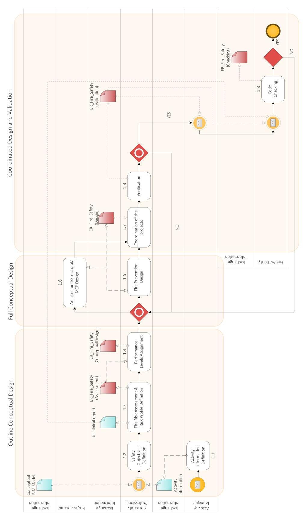
Draft of the Information Delivery Manual
153
Figure 100 | Process Map definition
4.3.3. MVD EXAMPLE
Having discussed the procedure to develop interoperability via the integrated IDM/MVD process, this section will introduce instances for Model View Definition in Fire Prevention Code Checking. To define an MVD after extraction of the information in paragraph §4.2 we technically translate them using the concepts templates provided by the IFC standards. The tool IfcDoc was used to create a draft of the MVD. To run the ifcDoc application, a base file must first be imported. This basic file contains the complete IFC schema specification and a pre-selected set of a dynamic MVD concept definition so that the operator does not have to program it elaborately himself. This tool allows to the expansion of the generic MVD concepts easily and simplifies the whole process of development.
Firstly, we defined a Model View Definition by adding a new item under the tree. Then within the MVD, we define the ERs being covered by the MVD. By inserting Table Definition, we added the concept roots (represents a class of objects for which the same constraints apply) to the Model View, then we select the IFC entity the concept root maps to. After that, we added requirements to the IFC entities by inserting Column Definition to attribute concepts (defines a constraint on applicable objects and how it is used in exchange requirements) to the concept root. Some of them were already defined in the file imported at the beginning, others have been created. Clicking on the MVD row in the diagram tree we can see the class diagram which is interesting to software developers because they quickly have a Model View of all the data definitions that are within scope. In the diagram, everything that is in solid black is a non-abstract entity so actually, it is a class that can be used so that it can have instances in IFC models. Everything grey is abstract and so they are not instantiated directly (Figure 101).
It should be noted that it is also possible to define user-defined properties with this tool. As can be seen in Figure 102 when inserting a property for a class it is possible to define the access status of that property. By defining a "READONLY" status it is possible to highlight in an MVD how that property can be read by everyone but only compiled by the owner of that property.
After that, we could try to produce documentation to create a publication of the MVD just defined. The application automatically generates IFC entity instantiation diagrams as well as MVD documentation in HTML format. The publication is built on the IFC support schema. Under the Scope, we can see which requirements are mandatory defined in the MVD (Figure 103). Under the Fundamental concepts and assumptions which are the concepts. Whereas under the section Diagrams we can see which the concept templates are using for each entity. The publication generated both human reading specifications and a file in mvdXML (Figure 104).
154
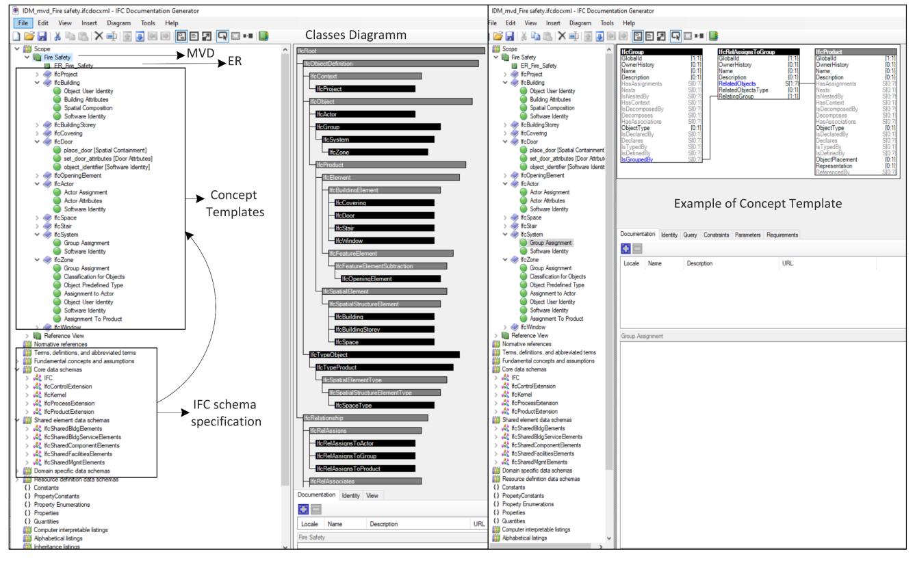
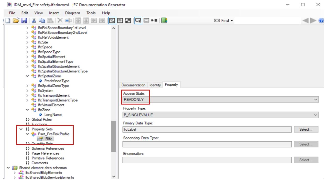
Draft of the Information Delivery Manual 155
Figure 101 | Steps to defined the MVD in the IfcDoc tool
Figure 102 | Property definition in the IfcDoc tool
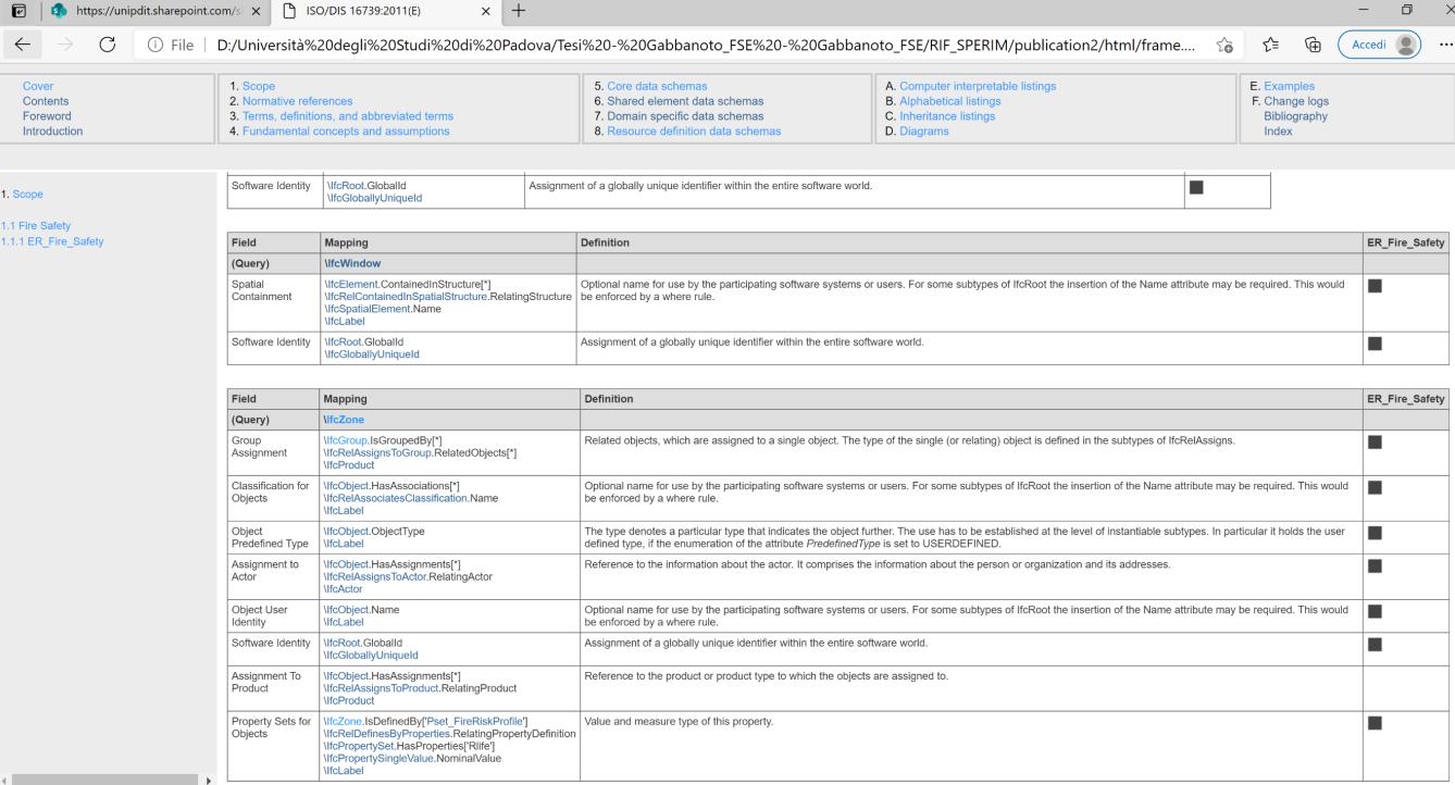
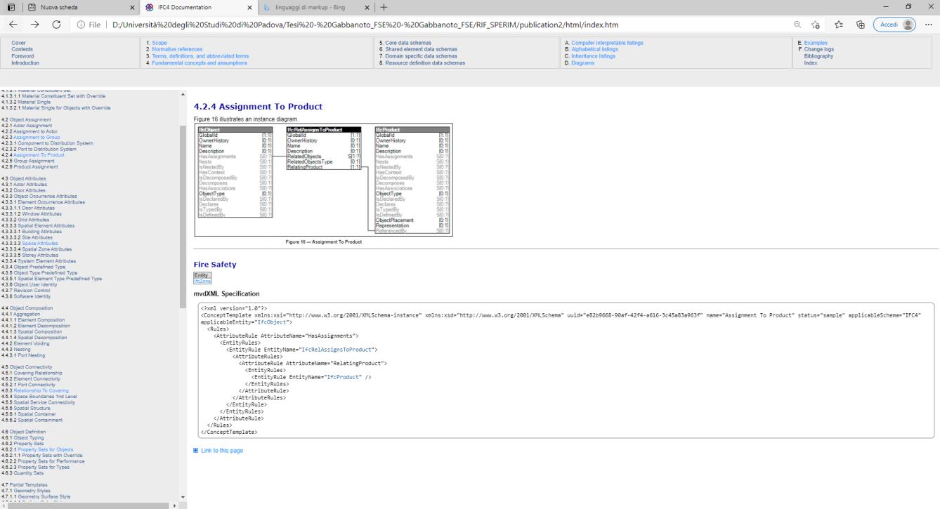
156
Figure 103 | Scope section of the MVD defined
Figure 104 | Diagrams section of the MVD defined
157
Due to the amount of information exchanged between the various stakeholders involved in the fire prevention discipline and required for the code checking of projects by the Fire Authority, the creation of an open and interoperable dataset is fundamental to reduce the time and costs of design and checking procedures.
The research conducted shows that, to date, the digitisation of data in the field of fire prevention is possible but still immature. The analysis of the information set by one side and of the IFC standard by the other highlighted a lack of integration between the IFC standard and the fire prevention discipline and a semantic incongruity between some parameters related to Fire Safety already implemented by BuildingSMART and the requirements of the Italian fire prevention regulations. The problems encountered are mainly since this discipline is a horizontal discipline with a very large impact on design and to the fact that the matter is a national competence with every State having its national regulation written in a not machine-readable format. Aiming to complete the standard for all countries is an optimistic vision but implementing the standard at least with the generally shared information is something necessary; it will then be a national competence to complete it with the missing parameters.
Figure 105 wants to show the current maturity of the IFC standard regarding the Fire Safety domain. Of the analysed requirements only 47 % have a clear correspondence in the IFC dataset in terms of entities, attributes, and properties. For the remainder (53%), an attempt was made to assume solutions to fill the gaps in the standard. Where possible, the hypotheses formulated try to rely on the existing dataset so as not to overload the standard with unnecessary parameters, while others involve new parameters. Although fire safety is a national matter, many concepts are at least in the European context shared. Thus, even if the requirements are interpreted differently in national contexts, the parameters and objects of the requirements are shared. In fact, of the 53% of the analysed parameters that are not directly reflected in the IFC data model, only 15% are strictly related to the Italian context.
The gaps that the standard presents today derive from the fact that being very complex, it is mainly addressed to people involved in the digitisation of processes. The creation of a research team that brings together not only specific figures competent in digitisation but also those in the field of the subject under examination would help to fill the gaps in both disciplines and to implement the dataset correctly. In this, the research has highlighted how the definition of an Information Delivery Manual (IDM), to write the exchange requirements for a specific process that would benefit from an IFC based information exchange, is the solution to implement the standard. In this respect the proposed draft is not complete, it is simply meant to be an example of how BuildingSMART not only pursues standardisation of information but also of the processes to generate this information.
The definition of a dataset for the exchange of information in the field of fire prevention is end in itself if it is not then implemented correctly in a BIM authoring software able to generate the
158
5. CONCLUSIONS
information to be mapped in an IFC model, and at the same time in software for code checking and for the simulation of analysis that import the IFC model to verify the requirements or implement the analysis. Figure 106 summarises the considerations made about the maturity of the modelling software used, Autodesk Revit 2021 and Graphisoft Archicad 24. Only 67 % of the analysed parameters are exportable with Autodesk Revit 2021, while 85 % are exportable with Graphisoft Archicad 24. Therefore, the implementation of the IFC standard will have to go hand in hand with the drafting of a Model View Definition (MVD) to address software suppliers who must implement the defined Information Delivery Manual (IDM) in software products.
Draft of the Information Delivery Manual 159
Figure 105 | IFC standard maturity
47% 36% 15% 2% 53% Parameters found in IFC Assumptions with the current IFC dataset User-defined Property Sets Assumptions & user-defined Property Sets 85% 15% Graphisoft Archicad 24 Exportable parameters Unexportable parameters 67% 33% Autodesk Revit 2021
parameters
Figure 106 | Comparison of IFC export maturity of Graphisoft Archicad 24 and Autodesk Revit 2021
Exportable
Unexportable parameters
This Appendix shows some of the necessary concepts and attributes that have been extracted.
Activity manager: the party that bears responsibility for fire prevention obligations for the activity.
Fire safety professional: a certified technician registered in a professional registry at the Ministry of the Interior as set out in Article 16 of Legislative Decree No 139 of 8th March 2006.
Subject activity: activities subject to fire prevention inspections by the National Fire Service.
Note Subject activities are recognised in Annex I to Presidential Decree No 151 of 1st August 2011. Definition Activity; Descrizione; Seleziona attività;
160
APPENDIX 1
n Referen ce Article Classificatio n Object(s) Namirial Parameter Parameter Relations Clearly mapped in IFC Assumptio n with existed DataSet new parameters software impleme ntation 1 G.2.6 Location of the activity Definition Building; Indirizzo attività Activity address YES NO NO NO 2 G.1.6
Definition
Legale
Activity
FireResist ancePerf ormance Level; YES NO NO YES
Activity; Actor;
rappresentan te
manager;
3 G.1.6
Definition Project;
Fire safety professional; YES NO NO NO
Actor;
4 G.1.5
Activity parameters: Identification; Description; Category; Member spaces & Compartment
Commpa rtment paramet ers: Identifica tion; Descripti on; Member spaces; NO YES NO YES (Graphiso ft Archicad 24)
s;
Outdoor activity: an activity or portion of an activity, including its evacuation routes, carried out in a defined area and mainly in an open-air space, which allows smoke and heat from the fire to escape directly into the atmosphere.
161 5 Definition Project; Tipo Intervento: Nuovo insediamento Modifica impianti o strutture attività esistente Ampliamento esistente maggiore del 50% Adeguament o esistente Modifiche non sostanziali Type of project; YES NO NO NO 7 Definition Activity; Attività aperta al pubblico Activity open to the public YES NO NO NO 8
Definition Activity; Attività all'aperto Outdoor activity YES NO NO NO 9 Definition Activity; Presenza persone con ridotte o impedite capacità motorie Presence of disabled people; YES NO NO NO 10 Definition Building; Descrizione Building Description; YES NO NO NO
11 G.1.7
Compartment reference floor: floor of the external location toward which the evacuation of the occupants of the compartment will primarily take place and from which the rescuers will gain access. If there is no such floor with these characteristics, then the floor where rescuers access the area with the best operational fire safety characteristics shall be considered (Chapter S.9). Each compartment shall have a single reference floor determined, which will generally correspond with the public or private access roadway. Determination of the compartment reference floor shall be noted in the design.
12 G.1.7
Compartment height: the difference between the level of the compartment floor and its reference floor. In the case of a multi-floor compartment, the greatest height difference shall be assumed as the absolute value. (e.g. for the highest compartment floor above ground, or for the lowest compartment floor below ground level).
13 G.1.7 Floor height: height difference between the floor and its relevant compartment reference floor.
14 G.1.7
Fire prevention height: maximum floors height of the activity. Floors that are occupied only occasionally and for brief periods, such as equipment floors and rooms, are excluded.
162
Definition Storey; Compartment reference floor; Floor reference floor; Storey Elevation ; Compart ment elevation ; NO YES YES YES
Definition Compartme nt; Compartment elevation; Compart ment referenc e floor; NO YES NO YES
Definition Storey; Quota Piano [m] (Quota rispetto al piano di riferimento) Storey Elevation; Floor referenc e floor; NO YES NO NO
Definition Building; Altezza antincendio Fire prevention height; Floor referenc e floor; NO YES NO NO
Definition Building; Altezza in gronda [m] Eaves Height YES NO NO NO
Definition Building; Altezza costruzione [m] Building Height YES NO NO NO
15
16
The possibility of approaching the buildings with the open auto-ladder as shown in image S.9-2 at least one window or balcony of each floor at a height of > 12 m must be ensured.
a defined portion of the activity with the characteristic or quality described in the specific measure.
Note The setting may refer to all or part of the activity. For example: floor, compartment, construction works, specific risk area, outdoor area, roof shed area, etc.
Gross floor area in a setting: a plan view floor area within the internal perimeter of the walls delimiting the setting.
Available floor area of ventilation openings is the floor area of the opening measured less any obstructions (e.g. frame, grate, fins, etc.).
163 17
Definition Building; Accostament o autoscale (SI/NO) Stickability of the ladder NO NO YES NO 18 Definition Storey; Nome Piano Floor Name YES NO NO NO 19 G.1.7
Definition Storey; Piani fuori terra Above ground floor; YES NO NO NO 20 Piano terra YES NO NO NO 21 G.1.7 Underground
or floor with a negative height. Definition Storey; Piani interrati Underground floor; YES NO NO NO 22 Piani seminterrati YES NO NO NO 23 G.1.7
Above-ground compartment or floor: compartment or floor with a positive height.
compartment or floor: compartment
Setting:
Definition Setting; Identification; NO YES NO YES (Graphiso ft Archicad 24) 24 G.1.7
Definition Activity; Setting; Compartme nt; Superficie Piano [m2] Gross floor area of Comportmen t [m2] YES NO NO YES 25 G.1.7
Definition Activity; Setting; Compartme nt; Superficie aerazione [m2] Ventilation area NO YES NO YES 26 Definition Storey; Altezza Piano [m] (Altezza massima tra pavimento e intradosso del soffitto) Floor height YES NO NO YES
See Table G.3.1
Fire Residual Risk: The designer shall use an industry standard method for assessing fire risk, depending on the complexity of the activity being handled.
Specific design fire load: the specific fire load corrected based on the fire risk indicator parameters of the fire compartment and the factors concerning the fire prevention measures present. This makes up the reference levels for the assessment of fire resistance of construction works.
δocc: prevailing characteristics of the occupants who shall be in the fire compartment;
See Table G.3.2
Activity; Compartme nt;
Characteristic s of the speed of the propagation of the fire;
risk profile; NO
YES
164 27 Definition Storey; N. persone presenti (pubblico) Occupants number Member spaces; Occupan cy Number; NO YES NO YES 28 Definition Storey; Accesso persone con ridotte o impedite capacità motorie (SI/NO) Handicap Accessible Member spaces; NO YES NO YES
30 G.2
performanc e-based Activity; Compartme nt; Rischio Residuo (Programma Valutazione del Rischio) Fire Residual Risk YES NO NO YES
31 G.1.12
Definition Compartme nt; Carico di incendio specifico di progetto qfd Specific design fire load [MJ/m2] NO NO YES YES
G.3.2
32
*BS 9999
Definition
Compartme
δ Occ Characteristic s of the occupants; RLife risk profile; YES NO NO YES
Activity;
nt;
33 G.3.2 *BS 9999
δα: prevailing characteristics of the speed of the propagation of the fire referred to the time tα in seconds used by the thermal potential to reach 1000 kW. RLife
Definition NO YES
δ a *Imposta manualmente
The Rlife risk profile shall be assigned to each compartment and, where necessary, for each open-air space of the activity, as referred to in Section G.3.2.
δα: prevailing rate of the growth of fire characteristic, referring to the time tα in seconds, used by the thermal potential to reach 1000 kW.
The Rlife risk profile is assigned in relation to the following factors:
δocc: prevailing characteristics of the occupants;
Activity; Compartme nt; R vita NO NO YES YES
profile;
35 G.3.3
37 G.3.3
The assignment of the Rprop risk profile is performed according to the strategic nature of the entire activity or of the settings (areas) that constitute the activity, and of any historic, cultural, architectonic or artistic value it or its contents may have.
Definition Activity; R Beni
Rprop risk profile;
NO NO YES YES 36 G.3.3
Restricted activity or area;
Rprop risk profile; NO NO YES YES
Definition Activity; Building; Opera da costruzione vincolata Rprop risk profile;
Strategic activity or area; Restricte d activity or area; Fire
YES NO NO YES
165 34 G.3.2 *BS
9999 See Table G.3.3-4
RLife risk
Prescriptive performanc e-based Characte ristics of the occupant s; Characte ristics of the speed of the propagati on of the fire; Fire Resistanc e Performa nce Level; Fire Reaction Performa nce Level;
an activity or setting (area) is considered restricted in its use because of art or history if it or its contents are considered such by law;
Strategic activity or area;
an activity or setting (area) is considered strategic if considered such by law or in consideration of public rescue and civil defence planning or upon indication of the activity manager.
Definition Activity; Opera da costruzione strategica
The designer assesses the Renv risk profile in the event of fire, distinguishing the settings (areas) of activity in which this risk profile is significant, from those where it is not significant.
166 Resistanc e Performa nce Level; 38 G.3.4
prescriptive performanc e-based Setting (Area); R ambiente Renv risk profile; NO NO YES YES
Tables S.1-2 e S.1-3 provide the generally accepted criteria for the assignment of individual performance levels.
Evacuation routes [1] not included in the other assignment criteria. or
Rooms not included in the other assignment criteria.
Evacuation routes [1] of the compartments with Rlife risk profile in B1. or
Rooms in compartments with Rlife risk profile in B2, B3, Cii1, Cii2, Cii3, Ciii1, Ciii2, Ciii3, E1, E2 and E3.
Evacuation routes [1] of the compartments with Rlife risk profile in B2, B3, Cii1, Cii2, Cii3, Ciii1, Ciii2, Ciii3, E1, E2, E3. or
Rooms in compartments with Rlife risk profile in D1, D2.
Evacuation routes [1] of the compartments with Rlife risk profile in D1, D2. or
Upon specific request by the customer, as provided for by design technical specifications, required by the competent authorities for structures intended for activities of particular importance.
167 39 S.1.3 See tables S.1-2 & S.1-3
I
II
III
IV
prescriptive performanc e-based Setting (Area); Compartme nt;Space Livello / Livello altri locali Fire Reaction Performance Level; RLife risk profile; Space in escape route or not; NO NO YES YES
See tables
S.1-5S.1-8
The following are the deemed-to-satisfy solutions, for each performance level, for the GM0, GM1, GM2, GM3, GM4 groups of materials defined in Section S.1.5.
1. The use of materials from the GM3 group is considered to be a deemed-to-satisfy solution.
1. The use of materials from the GM2 group is considered to be a deemed-to-satisfy solution.
1. The use of materials from the GM1 group is considered to be a deemed-to-satisfy solution.
S.1.4
Regardless of the deemed-to-satisfy solutions adopted for cladding, it is in any event permitted that 5 % of the gross internal floor area, in the evacuation routes or the activity's rooms (e.g. sum of the gross internal surface area of the ceiling, walls, floor and openings of the room), may be made up of materials installed on walls or floors included in the GM4 group of materials.
S.1.7
On facades (facings), cladding materials must be used that limit the probability of fire and its subsequent propagation due to the possibility of fire of external or internal origin with flames and hot smoke that come out of spaces, openings, cavities or seams.
Note Reference should be made to the circulars DCPST No 5643 of 31st March 2010 and DCPST No 5043 of 15th April 2013 containing technical guidance on ‘Fire safety requirements for facades (facings) on civil buildings’.
168 40
S.1.4
Prescriptive Covering; Furniture; Duct; Cable Carrier; Cable; Insulation; FireReact ion; Fire Reaction Performa nce Level; NO YES NO YES 41
Prescriptive Covering; Space Gross Floor Area; FireReact ion; NO YES NO YES 42
Prescriptive Curtain wall; FireReaction; YES NO NO YES
G.1.12; S.2.12
1. Fire resistance: one of the fire protection measures to be pursued to guarantee an appropriate level of safety for construction works in fire conditions. This concerns the load-bearing capability in case of fire, of a structure, a part of a structure or a structural element, as well as the capacity for compartmentalisation in case of fire for the structural separation elements (e.g. walls, ceilings, etc.) and non-structural elements (e.g. doors, partitions, etc.).
2. Load-bearing capability in case of fire: the capability of a structure, a part of a structure or a structural element, to maintain sufficient mechanical resistance during a fire, also considering other acting actions.
3. Compartmentalisation capability in case of fire: the ability of a constructional element to retain, under the action of fire, sufficient thermal insulation and a sufficient seal against smokes and hot combustion gases, as well as all other performance levels as required.
Construction works, including any adjacent service works and technical installations for utilities, where in all of the following conditions have been met:
45 S.2.3
● compartmentalisation with respect to other construction works that may be adjacent and structurally separated from them and such that any structural collapse does not cause damage to other construction works or outside of the border of the area on which the activity is located;
● used for activities relating to a single activity manager and with a Rprop risk profile equal to 1;
● not used for an activity requiring the presence of occupants, except for occasional staff for brief periods of time.
prescriptive
performanc e-based
Wall; Ceiling; Beam; Column; Slab; Roof; Stair; Covering; CurtainWall ; resistance; YES NO YES YES
Fire
169 44
Definition
Performance level I
Fire Resistance Performance Level; open-air separatio n distance; compart mentalisa tion; activity manager; RLife risk profile; Rprop; number of occupant s; crowding NO YES YES YES
Performance level II : Construction works or
Building;
portions of construction works, including any adjacent service works and technical installations for utilities, where all of the following conditions have been met:
● compartmentalisation with respect to any adjacent construction works;
● structurally separated from other construction works and such that any structural collapse does not cause damage to them or outside of the border of the area on which the activity is located; or, in the absence of structural separation, such that any failure of a portion does not cause damage to the rest of the construction works or outside of the border of the area on which the activity is located;
● used for activities relating to a single activity manager and with the following risk profiles:
○ Rlife included in A1, A2, A3 and A4;
○ Rprop equal to 1;
● crowding density ≤ 0.2 persons/m2;
● not generally intended for occupants with disabilities;
● all floors located at a height between -5 m and 12 m.
Performance level III: Construction works not included in the other assignment criteria. Performance level IV, V: Upon specific request by the customer, as provided for by the design technical specifications, required by the competent authorities for construction works intended for activities of particular importance.
3. The minimum fire resistance class must be at least 30 or less, if permitted by performance level III for the specific qf,d design fire load of the compartment in question.
density; Presence of disabled people; storey elevation ;
Fire resistanc e; YES
NO
Wall; Ceiling; Beam; Column; Slab; Roof; NO YES
170
48 S.2.4
Prescriptive
50 S.2.4
2. The minimum fire resistance class shall be drawn for each compartment as concerns the specific qf,d as indicated in Table S.2-3.
Stair; Covering; CurtainWall ;
Wall; Ceiling; Beam; Column; Slab; Roof; Stair; Covering; CurtainWall ;
I
Not allowed in the activities subject to fire regulations
II
56 S.3.3
III
This may apply in particular in the case of compartments with an Rlife risk profile that falls within D1, D2, Cii2, Cii3, Ciii2, Ciii3, in order to protect occupants who are sleeping or receiving medical treatment. prestazione
performanc e-based Compartme nt; Livello di RLife risk profile; Fire Residual Risk
NO NO YES YES
171
Prescriptive Fire resistanc e; NO NO NO YES
Required criteria for the performance levels In relation to the results of the risk assessment and Rlife risk profile.
Premises not covered by the other required criteria
In relation to the results of the risk assessment within settings (areas) of the same premises and in neighbouring areas (e.g. densely occupied premises, premises with a complex geometry or high specific fire load qf, the presence of significant quantities of hazardous substances or mixtures, the presence of hazardous works presenting a fire risk, etc.).
prescriptive Compartment alisation Performance Level;
57 G.1.8
Fire compartment (or compartment): a part of a construction set up to respond to safety requirements in case of fire; it is delimited by construction products or elements suitable to ensure fire resistance for a given time interval. In the event that no compartmentalisation is provided for, the compartment shall be considered the entire building structure.
Type of Compartment (Smokeproof Compartment; Filter; Smokeproof Filter)
Filter: a fire compartment in which the probability of fire ignition and development is considered negligible, in particular due to the absence of fire ignition points and to the low specific fire load qf admitted.
58 S.3.5
Protected type (or protected): a qualification of an activity space making up a fire compartment. Smoke-proof type (or smoke-proof): a term indicating the ability of a compartment to limit the entry of smoke generated by fire that develops in a communicating compartment.
External type (or external): the qualification of a portion of the activity external to the construction works, with the characteristics to temporarily counteract the propagation of fire coming from the construction works.
59 G.1.7
Gross floor area in a setting: a plan view floor area within the internal perimeter of the walls delimiting the setting. Definition Compartme nt; Superficie [m2];
172
Definition Compartme nt; Compartment parameters: Identification; Description; Member spaces; Activity paramet ers: Identifica tion; Descripti on; Category; Member spaces & Compart ments; YES NO NO YES
Definition Compartme nt; Type of compartment ; NO YES NO YES
Gross floor area of Comportmen t: . Crowd; Occupant density; YES NO NO YES
60 G.1.7
Available compartment area of ventilation openings is the floor area of the opening measured less any obstructions (e.g. frame, grate, fins, etc.).
The maximum crowd size in each room is determined:
a. by multiplying the occupant density from Table S.4-12 by the gross surface area of the room in question.
b. by applying the criteria of Table S.4-13;
c. according to the indications of the vertical technical rule.
Non adibito ad attività che compartino presenza di occupanti, ad esclusione di personale specificatame nte formato oppure occasionale con
di breve durata
Not used for activities involving the presence of occupants, with the exception of specially trained staff or occasional short-stay workers
173
Definition Activity; Setting; Compartme
Superficie aerazione [m2] Ventilation area YES NO NO YES
Definition Compartme nt; Tipo attività compartimen to Description of Compartment YES NO NO YES
nt;
61 S.4.6.2 Type of premises
62 S.4.6.2 Table S.4-13
Definition Compartme nt; Massimo affollamento Crowd; Occupant density; Gross floor area of Comport ment:. YES NO NO YES 68 Definition Compartme nt; Presenza persone con
capacità motorie Presence of people with reduced or impaired mobility YES NO NO YES 69 Definition
ridotte o impedite
Compartme nt;
permanenza
YES
NO NO YES
71 S.3.6
The gross surface area of the compartments must not exceed the maximum values stipulated in Table S.3-6 according to the Compartment height ( the difference between the level of the compartment floor and its reference floor. In the case of a multi-floor compartment, the greatest height difference shall be assumed as the absolute value) and the Rlife risk profile.
72 S.3.6
The presence of multi-storey compartments is permitted under the conditions of Table S.3-7, based on the Rlife risk profile of the compartments and the geometric characteristics of the building.
73 S.3.7
All fire doors between compartments must have the same fire resistance rating and be equipped with a self-closing device (e.g. doors) or be kept permanently closed (e.g. doors to plant rooms).
74 S.3.7
All fire doors between compartments and escape routes within the same premises should meet at least criteria E (integrity) and Sa (smoke leakage). The insulation (I) and radiation (W) criteria are not normally required.
76 S.4.5.7-8 & G.1.9.
174
prescriptive Compartme nt; Max Gross Area; Compart ment elevation ; Gross floor area of Comport ment:. RLife risk profile YES NO NO YES
prescriptive Compartme nt; Compart ment elevation ; RLife risk profile YES NO NO YES
prescriptive Door; self-closing device Doors between compart ments; YES NO NO YES
prescriptive Door; Smoke stop; Fire rating of the door; Fire Exit Comport ment; YES NO NO YES
Definition Door; Doors along escape routes NO YES NO YES
Fire
Comportment; Definition Door; Uscite associate al comparto Fire Exit Comportmen t; NO YES NO YES
75 S.4.5.7-8 & G.1.9. Doors along escape routes
Exit
82 G.1.9
Fire exit (or emergency exit): an opening in the reference floor evacuation system, which leads outside to a safe area.
Floor exit: a passage through the evacuation system that leads into a vertical evacuation route from a horizontal evacuation route.
The performance levels attributable of the settings (areas) of the premises for this fire protection measure are two. No deemed-to-satisfy solution is indicated for the performance level II.
The evacuation methods laid down are as follows:
a. simultaneous evacuation;
b. phased evacuation;
c.
Evacuation system: a set of life-saving measures that allow occupants to reach a safe area or remain safe, independently or with assistance, before the fire leads to incapacitating conditions in the areas of activity where they are located.
Note The evacuation system consists of safe areas, evacuation routes, exits, doors, emergency lighting, signs, etc.
175
S.4.5.7-8
G.1.9.
Definition Door; Doors between compartment s; NO YES NO YES
S.4.5.7-8
77
&
Doors between compartments;
78
& G.1.9.
Definition Door; Final Exit Door YES NO NO YES
S.4.5.7-8
G.1.9.
Definition Door; Floor exit NO YES NO YES
S.4.3
79
&
80
prescriptive performanc e-based Compartme nt; Livello Evacuation Performance Level; RLife risk profile; Fire Residual Risk NO NO YES YES
S.4.1
81
definition Setting; evacuation methods NO YES NO YES
progressive horizontal evacuation;
definition Escape Route; building elements that are part of it NO YES NO YES (Graphiso ft Archicad 24)
A place of ultimate safety for the premises must comprise at least one of the following solutions:
a. a public road,
b. any other open-air space that is safely linked to a public road in any fire situation, that is not affected by the products of combustion, in which the maximum radiation from the fire reaching the occupants is limited to 2.5 kW/m2, in which there is no risk of structural collapse, that is suitable for holding the occupants who use it during their evacuation.
With regard to a compartment, a temporary place of safety is deemed to be any other compartment or uncovered space, that can be crossed by the occupants to reach the place of ultimate safety as part of the evacuation system without re-entering the compartment in question
176 83 S.4.5.1
definition public road, any other open-air space place of ultimate safety NO YES NO YES
S.4.5.2
85
definition compartme nt or uncovered space temporary place of safety NO YES NO YES 86 S.4.5.3 Protected exit pathways (e.g. corridors, stairs, ramps, foyers, etc.) must be in dedicated protected spaces. prescriptive Escape Route; protected escape route NO YES NO YES (Graphiso ft Archicad 24) 87 S.4.5.3 Smokeproof exit pathways (e.g. corridors, stairs, ramps, foyers, etc.) must be in dedicated smokeproof spaces. prescriptive Escape Route; smoke proof escape route NO YES NO YES (Graphiso ft Archicad 24)
88 S.4.5.3
The smokeproof escape stairs must lead to a place of ultimate safety either directly or through a smokeproof exit pathway. When the exit pathway to a place of ultimate safety is only protected, the entire escape route can be considered equivalent to a protected escape route
89 S.4.5.4
Unprotected escape routes are all those that are not classified as protected, smokeproof or external.
The maximum crowd size in each room is determined:
90 S.4.6
a. by multiplying the occupant density by the gross surface area of the room in question.
b. by applying the criteria of Table S.4-13;
c. according to the indications of the vertical technical rule.
91 S.4.6
Each component of the evacuation system is sized on the basis of the most severe, for evacuation purposes, of the Rlife risk profiles of the compartments served
To avoid the spread of fire effluents to the escape routes:
92 S.4.7
prescriptive Door;
NO
FireRating; NO YES NO YES
177
prescriptive Escape Route; smoke proof escape route NO YES NO YES (Graphiso ft Archicad 24)
prescriptive Escape Route; unprotected escape route NO YES NO YES (Graphiso ft Archicad 24)
definition Space; Crowd; Occupant density; Gross surface area of the room YES NO NO YES
definition Escape Route; Rlife risk profiles NO NO YES YES
FireRating;
a. the vertical escape routes connecting the premises’ compartments must be protected by doorways with a fire resistance determined according to chapter S.2 and in any case with a rating of no less than 30 with fire doors of at least E 30-Sa; YES NO
YES
93 S.4.7
or smokeproof vertical escape routes coming from connected compartments, the use of fire doors rated at least E 30 is permitted. prescriptive Door;
94 S.4.7
To prevent the spread of fire effluents to the above-ground escape routes, when the building has storeys with an elevation < -5 m, the underground escape routes, if they are not smokeproof, must be in separate compartments to those of the above-ground escape routes.
To evacuate the occupants from the building’s most remote storeys, depending on the reference Rlife risk profile (paragraph S.4.6.1):
prescriptive Escape Route;
95 S.4.8
a. when there are storeys with an elevation above that listed in Table, all above-ground storeys must be served by at least two independent escape routes;
b. when there are storeys with an elevation below that listed in Table, all underground storeys must be served by at least two independent escape routes.
prescriptive Escape Route;
97 S.4.8
In order to limit the likelihood of localised overcrowding occurring at the exits, each room or open-air space of the premises must have at least the number of independent exits specified in Table S.4.15 based on the reference Rlife risk profile and the crowd size in the setting (area) served.
prescriptive Escape Route;
98 S.4.8
In order to limit the time required by the occupants to evacuate the compartment in which the fire broke out, at least one of the travel distances determined from any point of the premises must not exceed the maximum Les values of Table S.4.25 according to the reference Rlife risk profile, as shown in Table S.4.25
prescriptive Escape Route; Escape Route Lenght
178
storey elevation ; kind of escape route NO YES NO YES
Rlife risk
storey
YES NO YES
profile,
elevation ; NO
(Graphiso ft Archicad 24)
room; YES NO NO YES
Rlife risk profile;cr owd
Rlife
YES NO YES
risk profile NO
(Graphiso ft Archicad 24)
99 S.4.8
When the first section of the escape route is composed of a dead-end corridor, the requirements relating to the travel distance, including the distance travelled in a dead-end corridor, and the conditions of paragraph S.4.8.2 for dead-end corridors, must also be verified.
100 S.4.8
Escape routes with filter characteristics and external escape routes can be omitted from the verification of the travel distance referred to in point 1, as it is deemed unlikely that a fire will break out in these locations.
minimum height of escape routes is 2 m.
179
prescriptive
Escape Route Lenght Rlife risk profile; kind of escape route NO YES NO YES (ARCHICA D)
Escape Route;
prescriptive Escape Route; Escape Route Lenght NO YES NO YES (Graphiso ft Archicad 24)
The
prescriptive
Escape Route Height Space height YES NO NO YES
101 S.4.8
Escape Route;
APPENDIX 2
This Appendix shows the exchange requirements and their translation into IFC. Each row of the table represents an information unit with the technical translation of the exchange requirements, specifying the associated classes, attributes, and properties. The information units have been collected by type of component. Property Sets highlights in red are Proposal for Ifc DataSet, those highlights in blue are user – defined Property Sets
Information Units
Project
Type of intervention
Activity
Identification
Entity/Pset/Attribute
IfcProject.ObjectType -> IfcLabel
IfcZone.Name -> IfcLabel
IfcZone.Description -> IfcLabel
IfcZone.ObjectType -> IfcLabel
IfcRelAssociatesClassification.RelatedObjects -> IfcDefinitionSelect
IfcRelAssociatesClassification.Name -> IfcLabel
IfcRelAssociatesClassification.RelatingClassification ->
IfcClassificationSelect
IfcClassificationReference.Location -> IfcURIReference
IfcClassificationReference.Name -> IfcLabel
Mapped Concept
Object User Identity Object Predefined Type
Category
IfcClassificationReference.Identification -> IfcIdentifier
IfcClassificationReference.Description -> IfcLabel
IfcClassificationReference.ReferencedSource ->
IfcClassificationReferenceSelect
IfcClassification.Source -> IfcLabel
IfcClassification.Name -> IfcLabel
IfcClassification.Location -> IfcURIReference
IfcZone.IsGroupBy -> IfcRelAssignsToGroup
Member spaces & Compartments
Accessibility
Acitivity Manager Assignment
Risk Assessment
Occupants characteristics
IfcRelAssignsToGroup.RelatedObjects -> IfcObjectDefinition
IfcRelAssignsToGroup.RelatingGroup -> IfcGroup
Pset_ZoneCommon.PubliclyAccessible -> IfcBoolean
Pset_ZoneCommon.IsExternal -> IfcBoolean
Pset_ZoneCommon.HandicapAccessible -> IfcBoolean
IfcActor.IsActingUpon -> IfcRelAssignsToActor
IfcRelAssignsToActor.RelatingActor -> IfcActor
IfcRelAssignsToActor.RelatedObjects -> IfcObjectDefinition
Pset_SpaceFireSafetyRequirements.FireRiskFactor -> IfcLabel
Pset_SpaceFireSafetyRequirements.FireGrowthRate -> IfcLabel
Pset_SpaceFireSafetyRequirements.SpecificDesignFireLoad -> IfcReal
Pset_SpaceOccupancyRequirements.OccupancyType -> IfcLabel
Classification Association
Group Assignment
Property Sets for Objects
Actor Assignment
Property Sets for Objects
Property Sets for Objects
Risk Profile Assignment
Pset_FireRiskProfile.Rlife -> IfcLabel
Pset_FireRiskProfile.Renv -> IfcLabel
Property Sets for Objects Building
180
Performance Level; Pset_FirePreventionStrategy.PerformanceLevelCompartmentalisation -> IfcLabel Property Sets for Objects
Activity manager
IfcActor.TheActor -> IfcActorSelect
IfcPerson.FamilyName -> IfcLabel
IfcPerson.GivenName -> IfcLabel
Identification
IfcPerson.PrefixTitles -> IfcLabel
IfcPerson.Roles -> IfcActorRole.UserDefinedRole -> IfcLabel
IfcPersonAndOrganization.ThePerson -> IfcPerson
IfcPersonAndOrganization.TheOrganization.IfcOrganization
Actor Attributes
Compartment
Identification
IfcZone.Name -> IfcLabel
IfcZone.Description -> IfcLabel
IfcZone.ObjectType -> IfcLabel
IfcZone.IsGroupBy -> IfcRelAssignsToGroup
Member spaces & Compartments
Gross floor area
IfcRelAssignsToGroup.RelatedObjects -> IfcObjectDefinition
IfcRelAssignsToGroup.RelatingGroup -> IfcGroup
Pset_ZoneCommon.GrossPlannedArea -> IfcAreameasure
Object User Identity Object Predefined Type
Group Assignment Assignment To Group
Property Sets for Objects
181 Identification IfcBuilding.Description -> IfcLabel Pset_BuildingCommon.IsLandmarked -> IfcLogical Pset_BuildingCommon.IsBuildingStrategic -> IfcLogical Object User Identity Property Sets for Objects Address IfcBuilding.BuildingAddress -> IfcPostalAddress IfcBuilding.BuildingAddress -> IfcPostalAddress.AddressLines -> IfcLabel IfcBuilding.BuildingAddress -> IfcPostalAddress.Town -> IfcLabel IfcBuilding.BuildingAddress -> IfcPostalAddress.Region -> IfcLabel IfcBuilding.BuildingAddress -> IfcPostalAddress.PostalCode -> IfcLabel IfcBuilding.BuildingAddress -> IfcPostalAddress.Country -> IfcLabel Building Attributes Risk Profile Assignment Pset_FireRiskProfile.Rprop -> IfcLabel Property Sets for Objects Entrance Floor Pset_BuildingCommon.EntranceLevel Pset_BuildingCommon.IsDrivewayEntrance Property Sets for Objects Fire prevention height; IfcBuildingStorey.Elevation -> IfcLengthMeasure Pset_BuildingCommon.EntranceLevel Pset_BuildingCommon.IsDrivewayEntrance Storey Attributes Property Sets for Objects Eaves Height Qto_BuildingBaseQuantities.EavesHeight -> IfcLengthMeasure Quantity Sets Building Height Qto_BuildingBaseQuantities.Height -> IfcLengthMeasure Quantity Sets Fire Resistance Performance Level; Pset_FirePreventionStrategy.PerformanceLevelFireResistance -> IfcLabel Property Sets for Objects Compartmentalisation
Ventilation area
IfcZone.IsGroupBy -> IfcRelAssignsToGroup
IfcRelAssignsToGroup.RelatedObjects -> IfcObjectDefinition
IfcRelAssignsToGroup.RelatingGroup -> IfcGroup
IfcSpace.BoundedBy -> IfcRelSpaceBoundary
IfcRelSpaceBoundary.RelatingSpace -> IfcSpaceBoundarySelect
IfcRelSpaceBoundary.RelatedBuildingElement -> IfcElement
IfcWindow.ContainedInStructure -> IfcRelContainedInSpatialStructure
IfcRelContainedInSpatialStructure.RelatedElements -> IfcProduct
IfcRelContainedInSpatialStructure.RelatingStructure -> IfcSpatialElement
Qto_WindowQuantities.Area -> IfcAreameasure
Pset_SpaceFireSafetyRequirements.FireRiskFactor -> IfcLabel
Pset_SpaceFireSafetyRequirements.FireGrowthRate -> IfcLabel
Risk Assessment
Occupants characteristics
Risk Profile Assignment
Pset_SpaceFireSafetyRequirements.SpecificDesignFireLoad -> IfcReal
Pset_SpaceFireSafetyRequirements.FlammableStorage -> IfcBoolean
Pset_SpaceOccupancyRequirements.OccupancyType -> IfcLabel
Pset_FireRiskProfile.Rlife -> IfcLabel
Pset_FireRiskProfile.Renv -> IfcLabel
Pset_ZoneCommon.GrossPlannedArea -> IfcAreameasure
Pset_SpaceOccupancyRequirements.OccupancyNumberPeak -> IfcCountMeasure
Group Assignment
Space Boundaries 1nd Level
Spatial Containment Quantity Sets
Maximum crowd
Pset_SpaceOccupancyRequirements.AreaPerOccupant -> IfcAreameasure
Pset_SpaceOccupancyRequirements.OccupancyNumber -> IfcCountMeasure
Pset_ZoneCommon.PubliclyAccessible -> IfcBoolean
Accessibility
Reference floor
Pset_ZoneCommon.HandicapAccessible -> IfcBoolean
IfcZone.HasAssignments -> IfcRelAssignsToProduct
IfcRelAssignsToProduct.RelatedObjects -> IfcObjectDefinition
IfcRelAssignsToProduc.RelatingProduct -> IfcProduct
IfcZone.IsGroupBy -> IfcRelAssignsToGroup
IfcRelAssignsToGroup.RelatedObjects -> IfcObjectDefinition
IfcRelAssignsToGroup.RelatingGroup -> IfcGroup
Property Sets for Objects
Property Sets for Objects
Property Sets for Objects
Property Sets for Objects
Property Sets for Objects
Product Assignment
Elevation
IfcSpace.ElevationWithFlooring -> IfcLengthMeasure
IfcBuildingStorey.Elevation -> IfcLengthMeasure
Product Assignment
Space Attributes
Storey Attributes
Fire Reaction
Performance Level;
Use for evacuation scope
Storey
Pset_FirePreventionStrategy.PerformanceLevelFireReaction -> IfcLabel
Pset_FireRiskProfiles.Rlife
Pset_SpaceFireSafetyRequirements.FireExit
Pset_SpaceFireSafetyRequirements.FireExit -> IfcBoolean
Identification; IfcBuildingStorey.Name -> IfcLabel
Position
Pset_BuildingStoreyCommon.AboveGround -> IfcLogical
Property Sets for Objects
Property Sets for Objects
Object User Identity
Property Sets for Objects
182
Accessibility
Pset_SpaceCommon.PubliclyAccessible -> IfcBoolean
Pset_SpaceCommon.HandicapAccessible -> IfcBoolean
IfcBuildingStorey.IsDecomposedBy -> IfcRelAggregates
IfcRelAggregates.RelatingObject -> IfcObjectDefinition
IfcRelAggregates.RelatedObjects -> IfcObjectDefinition
Pset_SpaceOccupancyRequirements.OccupancyNumber -> IfcCountMeasure
Property Sets for Objects
Spatial Composition
Occupants number
IfcBuildingStorey.IsDecomposedBy -> IfcRelAggregates
IfcRelAggregates.RelatingObject -> IfcObjectDefinition
IfcRelAggregates.RelatedObjects -> IfcObjectDefinition
IfcBuldingStorey.HasAssignments -> IfcRelAssignsToProduct
IfcRelAssignsToProduct.RelatedObjects -> IfcObjectDefinition
Property Sets for Objects
Spatial Composition
Reference floor
IfcRelAssignsToProduc.RelatingProduct -> IfcProduct
IfcBuildingStorey.Elevation -> IfcLengthMeasure
Product Assignment
Storey Attributes
Elevation
IfcBuildingStorey.Elevation -> IfcLengthMeasure
Height Qto_BuildingStoreyBaseQuantities.NetHeigtht -> IfcLengthMeasure
Space
Object geometry IfcProduct.Representation -> IfcProductDefinitionShape
Covering definition
Covering definition
Gross floor area
Occupants characteristics
IfcSpace.HasCoverings -> IfcRelCoversSpaces
IfcRelCoversSpaces.RelatingSpace -> IfcSpace
IfcRelCoversSpaces.RelatedCoverings -> IfcCovering
IfcSpace.BoundedBy -> IfcRelSpaceBoundary
IfcRelSpaceBoundary.RelatingSpace -> IfcSpaceBoundarySelect
IfcRelSpaceBoundary.RelatedBuildingElement -> IfcElement
Pset_SpaceCommon.GrossPlannedArea -> ifcAreaMeasure
Pset_SpaceOccupancyRequirements.OccupancyType -> IfcLabel
Pset_ZoneCommon.GrossPlannedArea -> IfcAreameasure
Pset_SpaceOccupancyRequirements.OccupancyNumberPeak -> IfcCountMeasure
Storey Attributes
Quantity Sets
Maximum crowd
Pset_SpaceOccupancyRequirements.AreaPerOccupant -> IfcAreameasure
Pset_SpaceOccupancyRequirements.OccupancyNumber -> IfcCountMeasure
Space Boundaries 1st Level
Quantity Sets
Property Sets for Objects
Property Sets for Objects
Use for evacuation scope
Door
Object geometry
Object placement
Function
Fire resistance
Dimensions
Pset_SpaceFireSafetyRequirements.FireExit -> IfcBoolean
IfcProduct.Representation -> IfcProductDefinitionShape
Pset_DoorCommon.FireExit -> ifcBoolean
Pset_DoorCommon.IsExternal-> ifcBoolean
Pset_DoorCommon.Firerating -> IfcLabel
Pset_DoorCommon.SelfClosing .> IfcBoolean
Pset_DoorCommon.SmokeStop -> IfcBoolean
Qto_DoorBaseQuantities.Area -> IfcAreaMeasure
Property Sets for Objects
Property Sets for Objects
Quantity Sets
183
Wall Connection
IfcDoor.FillsVoids -> IfcRelFillsElement
IfcRelFillsElement.RelatedBuildingElement -> IfcBuldingElement
IfcRelFillsElement.RelatingOpeningElement -> IfcOpeningElement
IfcOpening.VoidsElements -> IfcRelVoidsElement
IfcRelVoidElement.RelatingOpeningElement
IfcRelVoidElement.Relating
Pset_EvacuationLength.PreviousExitLength -> IfcLengthMeasure
Evacuation property
Window
Object geometry
Dimensions
Wall
Fire Resistance
Slab
Fire Resistance
Roof
Fire Resistance
Stair
Fire Resistance
Beam
Fire Resistance
Column
Fire Resistance
Covering
Object geometry
FireReaction
Pset_EvacuationLength.NextExitLength -> IfcLengthMeasure
IfcProduct.Representation -> IfcProductDefinitionShape
Qto_WindowQuantities.Area -> IfcAreameasure
Pset_WallCommon.Firerating -> IfcLabel
Pset_WallCommon.LoadBearing -> IfcBoolean
Pset_WallCommon.Compartimentation -> IfcBoolean
Pset_SlabCommon.Firerating -> IfcLabel
Pset_SlabCommon.LoadBearing -> IfcBoolean
Pset_SlabCommon.Compartimentation -> IfcBoolean
Pset_RoofCommon.Firerating -> IfcLabel
Pset_RoofCommon.LoadBearing -> IfcBoolean
Pset_RoofCommon.Compartimentation -> IfcBoolean
Pset_StairCommon.Firerating -> IfcLabel
Pset_StairCommon.LoadBearing -> IfcBoolean
Pset_StairCommon.Compartimentation -> IfcBoolean
Pset_BeamCommon.Firerating -> IfcLabel
Pset_BeamCommon.LoadBearing -> IfcBoolean
Pset_ColumnCommon.Firerating -> IfcLabel
Pset_ColumnCommon.LoadBearing -> IfcBoolean
IfcProduct.Representation -> IfcProductDefinitionShape
IfcCovering.PredefinedType -> IfcCoveringTypeEnum
Pset_CoveringCommon.FlammabilityRating -> IfcLabel
Pset_CoveringCommon.Combustible -> IfcLabel
IfcCovering.PredefinedType -> IfcLabel
Fire Resistance
Covers Space
Covers Space
Dimensions
Furniture
Fire Reaction
Pset_CoveringCommon.Firerating -> IfcLabel
IfcCovering.CoversSpaces -> IfcRelCoversSpaces
IfcRelCoversSpaces.RelatingSpace -> IfcSpace
IfcRelCoversSpaces.RelatedCoverings -> IfcCovering
IfcCovering.ProvidesBoundaries ->IfcRelSpaceBoundary
IfcRelSpaceBoundary.RelatingSpace -> IfcSpaceBoundarySelect
IfcRelSpaceBoundary.RelatedBuildingElement -> IfcElement
Qto_CoveringBaseQuantites.NetArea -> IfcAreaMeasure
Pset_FurnitureFireReacton.FlammabilityRating -> IfcLabel
Element Voiding
Property Sets for Objects
Quantity Sets
Property Sets for Objects
Property Sets for Objects
Property Sets for Objects
Property Sets for Objects
Property Sets for Objects
Property Sets for Objects
Property Sets for Objects
Object Predefined Type
Property Sets for Objects
Space Boundaries 1st Level
Quantity Sets
184
Member spaces
Evacuation property
Services spatial element
IfcSystem.Name -> IfcLabel
IfcSystem.Description -> IfcLabel
IfcSystem.ObjectType -> IfcLabel
IfcSystem.IsGroupBy -> IfcRelAssignsToGroup
IfcRelAssignsToGroup.RelatedObjects -> IfcObjectDefinition
IfcRelAssignsToGroup.RelatingGroup -> IfcGroup
Pset_EvacuationLength.DeadEndCorridorLength -> IfcLengthMeasure
Pset_EvacuationLength.OmittedLength -> IfcLengthMeasure
IfcSystem.ServicesBuilding -> IfcRelServicesBuildings
IfcRelServicesBuildings.RelatingSystem -> IfcSystem
IfcRelServicesBuildings.RelatedBuildings -> IfcSpatialElement
Object User Identity
Group Assignment
Property Sets for Objects
185 System
Identification
Object Predefined Type
BIBLIOGRAPHY
Abualdenien, J., Pfuhl, S., & Braunr, A. (2018). Development of an MVD for checking fire-safety and pedestrian simulation requirements [TUM]. https://www.researchgate.net/publication/333825074_BIMbased_code_compliance_checking_for_fire_safety_in_timber_buildings_A_comparison_of_ex isting_tools
Allione, S. (2020). Vie d’esodo nel codice di prevenzione incendi. https://fseng-antincendio.it/viedesodo-nel-codice-di-prevenzione-incendi/
Amaro, G. (2020a). Il continuo sviluppo ed evoluzione del Codice di Prevenzione Incendi Analisi della versione emanata con il D.M. 18/10/2019 - Parte 1. https://www.gaeengineering.com/rassegna-stampa/evoluzione-codice-prevenzione-incendi-parte-1/
Amaro, G. (2020b). Il continuo sviluppo ed evoluzione del Codice di Prevenzione Incendi Analisi della versione emanata con il D.M. 18/10/2019 - Parte 2. https://www.gaeengineering.com/rassegna-stampa/il-continuo-sviluppo-il-continuo-sviluppo-ed-evoluzionedel-codic-di-prevenzione-incendi-analisi-della-versione-em/
Amaro, G., & Passalacqua, M. (2018). Implementazioni BIM dello sviluppo della strategia antincendio nelle fasi di progettazione , costruzione e gestione. 1–11. https://www.ingenio-web.it/21459bim-e-strategia-antincendio-nelle-fasi-di-progettazione-costruzione-e-gestione-di-un-edificio Battistini, F. (2018). Esodo con approccio ingegneristico FSE.
Borin, P., & Zanchetta, C. (2020). IFC: Processi e modelli digitali openBIM per l’ambiente costruito Maggioli Editore.
Borrmann, A., Beetz, J., Koch, C., Liebich, T., & Muhic, S. (2018). Industry Foundation Classes: A Standardized Data Model for the Vendor-Neutral Exchange of Digital Building Models. In A. Borrmann, M. Konig, C. Koch, & J. Beetz (Eds.), Building Information Modeling: Technology Foundations and Industry Practice (pp. 81–126). Springer. https://doi.org/10.1007/978-3-31992862-3_13
Borrmann, A., & Preidel, C. (2018). BIM-Based Code Compliance Checking. In Building Information Modeling: Technology Foundations and Industry Practice (pp. 367–382).
BuildingSMART International. (2007). Quick Guide Business Process Modeling Notation
https://standards.buildingsmart.org/documents/IDM/IDM_guide-QuickGuideToBPMN2007_01.pdf
BuildingSMART International. (2016). The EXPRESS Definition Language for IFC Development.
https://web.stanford.edu/group/narratives/classes/08-09/CEE215/ReferenceLibrary/Industry Foundation Classes (IFC)/IFC General/The_EXPRESS_Definition_Language_for_IFC_Development.pdf
BuildingSMART International. (2020a). Fire Safety Engineering & Occupant Movement openBIM Standards. https://www.buildingsmart.org/standards/calls-for-participation/fire-safety/
BuildingSMART International. (2020b). Industry Foundation Classes: Version 4 - Addendum 2
https://standards.buildingsmart.org/IFC/RELEASE/IFC4/ADD2/HTML/
186
Chipman, T. ;, Liebich, T. ;, Weise, M., Chipman, T. ;, & Liebich, T. ; (2016). Document id Title Organisation /Author Date Status P9-002 mvdXML specification 1.1 Specification of a standardized format to define and exchange Model View Definitions with Exchange Requirements and Validation Rules Developed by Model Support Group (MSG) . BuildingSMART, 1, 49. http://buildingsmart-tech.org/mvd/XML/1.1
Cucurachi, G. (2016). Il Codice di Prevenzione Incendi e la Fire Safety Engineering https://www.puntosicuro.it/_resources/160912_intervento Cucurachi_Antincendio.pdf
Decreto del presidente della Repubblica 1° agosto 2011 , n. 151., (2011).
Decreto legislativo 18 aprile 2016, n. 50. Codice dei contratti pubblici, (2016).
Decreto Ministeriale 12 Aprile 2019 e successive modificazioni, Codice di prevenzione incendi (2020).
Decreto ministeriale 7 agosto 2012, (2012).
Dimyadi, J. A. W. (2007). Generating FDS Fire Simulation Input using IFC-based Building Information Model.
Dimyadi, J., & Amor, R. (2013). Automated Building Code Compliance Checking. Where is it at? Proceedings of the CIB World Building Congress 2013 and Architectural Management & Integrated Design and Delivery Solutions (AMIDDS), 380, 172
185.
Dimyadi, J., Clifton, C., Spearpoint, M., & Amor, R. (2014). Computer-aided Compliance Audit to Support Performance-based Fire Engineering Design. Proceedings of 10th International Conference on Performance-Based Codes and Fire Safety Design Methods, November https://doi.org/10.13140/2.1.5142.7521
Eastman, C., Lee, J. min, Jeong, Y. suk, & Lee, J. kook. (2009). Automatic rule-based checking of building designs. Automation in Construction. Automation in Construction, 18(8), 1011–1033. https://doi.org/10.1016/j.autcon.2009.07.002
EN 1991-1-2: 2002 Actions on structures - Part 1-2: General actions - Actions on structures exposed to fire, (2002).
Directive 2014/24/EU of the European Parliament and of the Council of 26 February 2014 on public procurement, (2014).
Fire National regulations 2020. (2020). https://cfpa-e.eu/national-regulations/ FU, Y. (2018). Automated Simulation of Visitors Streams from IFC Files (Issue May). https://tudresden.de/bu/bauingenieurwesen/cib/ressourcen/dateien/publikationen/Projekt_Diplomarbeiten/Yunyi-FU_Masterarbeit_2018.pdf?lang=en
Genova, G., & Adachi, Y. (2020). Building Room Session 4 - Potential Use Cases of IFC Spatial Zone https://vimeo.com/483131538
Harrell, R., & Mathews, M. (2018). Could Autodesk Revit 2018 Be Automated for Code Compliance Checking and Demonstration with A Focus on Fire Safety Regulations? https://arrow.tudublin.ie/bescharcrep
Holte Consulting. (2014). Status survey of solutions and issues relevant to the development of ByggNett
https://buildingsmart.no/sites/buildingsmart.no/files/20140711_byggnett_status_survey_rev_ 2014.pdf
187
–
ISO 29481-1:2016 Building information models Information delivery manual Part 1: Methodology and format, (2016).
ISO 19650-1:2018 Organization and digitization of information about building and civil engineering works. Including Building Information Modelling (BIM) - Information Management using Building Information Modelling. Part 1: Concept and principles, (2018).
ISO 19650-2: 2018 Organization and digitization of information about building and civil engineering works. Including Building Information Modelling (BIM) - Information Management using Building Information Modelling. Part 2: Delivery phase of the assets., (2018).
Jeon, K., & Lee, G. (2018). Information Delivery Manual ( IDM ) Configurator : Previous Efforts and Future Work Information Delivery Manual ( IDM ) Configurator : Previous Efforts and Future Work.
Karlshøj, J., See, R., & Davis, D. (2012). An Integrated Process for Delivering IFC Based Data Exchange. BuildingSMART International, 1, 53. http://iug.buildingsmart.org/idms/
Kincelova, K., Boton, C., Blanchet, P., & Dagenais, C. (2020). Fire safety in tall timber building: A BIMbased automated code-checking approach. Buildings, 10(10). https://doi.org/10.3390/BUILDINGS10070121
Lee, H., Lee, J. K., Park, S., & Kim, I. (2016). Translating building legislation into a computer-executable format for evaluating building permit requirements. Automation in Construction, 71, 49–61.
https://doi.org/10.1016/j.autcon.2016.04.008
Malsane, S. (2015). The Application of Automated Rule Checking to Existing UK Building Regulations Using BIM Technologies.
http://nrl.northumbria.ac.uk/25328/1/malsane.sagar_phd.pdf
Menduto, T. (2017). I vantaggi e la struttura del nuovo codice di prevenzione incendi.
https://www.puntosicuro.it/incendio-emergenza-primo-soccorso-C-79/normativa-antincendioC-87/i-vantaggi-la-struttura-del-nuovo-codice-di-prevenzione-incendi-AR-16510/
Nawari, O. (2019). A Generalized Adaptive Framework (GAF) for Automating Code Compliance Checking.
https://www.mdpi.com/2075-5309/9/4/86
Ordine Ingegneri di Sondrio. (n.d.). Classificazione dei metodi di analisi del rischio Valutazione del rischio d ’ incendio 1–17.
Pfuhl, S. (2018). Analysis of Exchange Requirements for BIM- based Fire Code Compliance Checking.
Preidel, C., & Borrmann, A. (2015). Automated code compliance checking based on a visual language and building information modeling. 32nd International Symposium on Automation and Robotics in Construction and Mining: Connected to the Future, Proceedings, July https://doi.org/10.22260/isarc2015/0033
Redaelli, R. (2020). Digitalizzazione del mondo AEC: openBIM e interdisciplinarietà https://www.ingenio-web.it/29534-digitalizzazione-del-mondo-aec-openbim-einterdisciplinarieta
Sabatino, R. (2014). Sicurezza antincendio. Valutazione del rischio incendio. INAIL.
https://www.inail.it/cs/internet/docs/allegato_sicurezza_antincendio_valutazione_rischio_inc endio.pdf
Sabatino, R., Freda, D., Pireddu, A., Baldassarini, S., Manna, S., Lombardi, M., Sciarretta, N., Caciolai, M., Cancelliere, P., Cosi, F., & Cascioli, V. (2018). Il codice di prevenzione incendi. La
188
progettazione antincendio Applicazioni pratiche nell’ambito del d.m. 3 agosto 2015 e s.m.i. INAIL.
https://www.certifico.com/component/attachments/download/10165
Sasso, A. (2019). La Protezione Passiva dal Fuoco: dalla normativa alla realtà di cantiere Latina, FILTRI A PROVA DI FUMO. https://www.ordineingegneri.latina.it/cms/sites/default/files/2019-0131_Presentazione_Filtri a prova di fumo_Ordine Ing. Latina.pdf
Solihin, W., & Eastman, C. (2015). Classification of rules for automated BIM rule checking development. Automation in Construction, 53, 69–82. https://doi.org/10.1016/j.autcon.2015.03.003
Sorensen, L. S. (2014). Fire Safety Engineering and Performance Based Codes. Polyteknisk.
Spearpoint, M. J. (2006). Integration of Building Product Models with Fire Simulation Software http://www.civil.canterbury.ac.nz/fire/pdfreports/MSpearpoint06.pdf
Taciuc, A., Karlshøj, J., & Dederichs, A. (2016). Development of IFC based fire safety assesment tools 2159(August), 1–12. http://itc.scix.net/cgi-bin/works/Show?_id=lc3-2017153%0Ahttp://orbit.dtu.dk/files/128480990/Untitled.pdf%0Ahttp://www.scopus.com/inward/ record.url?eid=2-s2.084907345635&partnerID=40&md5=8066ebcaac2683cac90ede5957d02c08%0Ahttp://orbit.dt u.dk/files/10504
UNI 11337-5: 2017 Construction and civil engineering - Digital management of construction information processes. Information flows in digitised processes., (2017).
UNI 11337-6: 2017 Construction and civil engineering - Digital management of construction information processes. Guidance to redaction the informative specific information., (2017).
Vermeulen, D. (2017). Fire Exit Risk Assessment with Revit and Dynamo. https://revitbeyondbim.wordpress.com/2017/01/03/fire-exit-risk-assessment-with-revit-anddynamo/
Wix, J., & Karlshøj, J. (2010). Information Delivery Manual Guide to Components and Development Methods (pp. 1–84). https://standards.buildingsmart.org/documents/IDM/IDM_guideCompsAndDevMethods-IDMC_004-v1_2.pdf
Zhang, C., Beetz, J., & Weise, M. (2014). Model view checking: Automated validation for IFC building models. EWork and EBusiness in Architecture, Engineering and Construction - Proceedings of the 10th European Conference on Product and Process Modelling, ECPPM 2014, 123–128. https://doi.org/10.1201/b17396-24
Zhu, Z., Zhou, L., Zhang, C., Lin, B., Cui, Y., & Che, M. (2018). Modeling of macroscopic building evacuation using IFC data. ISPRS International Journal of Geo-Information, 7(8). https://doi.org/10.3390/ijgi7080302
189
190 LIST OF TABLES Table 1 | IFC Formats (source: https://technical.buildingsmart.org/standards/ifc/ifc-formats/) 24 Table 2 | Software with IFC file import capability 40 Table 3 | Application methods of Ministerial Decree of 12 April 2019..............................................61 Table 4 | Proposed table for extraction of semantic..........................................................................68 Table 5 | Pset_BuildingCommon Property Set (only fire safety properties shown) 74 Table 6 | Pset_SpaceFireSafetyRequirements 76 Table 7 | Attributes of IfcClassificationReference 77 Table 8 | Attributes of IfcClassification 78 Table 9 | Entities/ Attributes/ Concept Templates to map in a IFC Model the subject activities 79 Table 10 | Duties of the designer and manager of the activity in the field of safety management design ............................................................................................................................................................82 Table 11 | Fire risk levels....................................................................................................................85 Table 12 | Fire Load Calculation (source: Annex I Ministerial Decree 12 April 2019 - S.2.9) .............85 Table 13 | Properties of Pset_SpaceFireSafetyRequirements 86 Table 14 | Property Sets of IfcMaterial 87 Table 15 | Assignment of Rprop (source: Annex I Ministerial Decree of 12 April 2019) 89 Table 16 | Tables of Ministerial Decree of 15 March 2005 integrated with the Ministerial Decree of 16 February 2009 for the conversion of Italian fire reaction classes from European fire reaction classes. 92 Table 17 | Classification in groups of materials for cladding and finishing ........................................93 Table 18 | Fire reaction and Fire Resistance in the IFC Standard.......................................................94 Table 19 | IfcBuildingElement subtypes and properties for fire behaviour 95 Table 20 | IfcCovering enumeration definition 95 Table 21 | Performance level and assignment criteria. Deemed to satisfy solutions (Annex I Ministerial Decree 12 April 2019 - S.2.4) 104 Table 22 | Properties of IfcBuildingElement subtypes for Fire Resistance measure 105 Table 23 | IfcZone/ifcSpatialZone ObjectType for Compartments 114 Table 24 ! Geometry of compartment .............................................................................................119
191 Table 25 | Firefighting stairs (Annex I Ministerial Decree of 12 April 2019 - S.4.5.3) 133 Table 26 | IfcZone/ifcSpatialZone ObjectType for Compartments 134 Table 27 | Pset_SpaceOccupancyRequirements 142 Table 28 | Escape Routes length checking...........................................................................143
192 LIST OF FIGURES Figure 1 | Design of Research process 12 Figure 2 | Interoperability relationships between several disciplines 13 Figure 3 | Contents of Legislative Decree 50/2016 (source: Borin & Zanchetta, 2020).....................15 Figure 4 | The essential structure of the Common Data Environment in PAS 1192-2 .......................17 Figure 5 | The Common Data Environment 17 Figure 6 | Exchange information process 18 Figure 7 | Comparison of EXPRESS representations for IfcActorSelect data type 22 Figure 8 | Comparison of EXPRESS representations for the IfcDoor class 23 Figure 9 | Comparison of EXPRESS representations for a relationship 24 Figure 10 | IFC-SPF file .......................................................................................................................26 Figure 11 | STEP file: representation of data aggregation .................................................................27 Figure 12 | IfcWall in graph expression 27 Figure 13 | STEP file: example of inverse attribute 27 Figure 14 | ifcXML file: representation of data aggregation 28 Figure 15 | An inverse attribute of IfcLocalPlacement in ifcXML file 28 Figure 16 | Data schema architecture with conceptual layers (source: BuildingSMART International) 31 Figure 17 | Relationship between Concept templates, attribute inheritance for IfcDoor entity (inspired by Borin & Zanchetta, 2020)................................................................................................32 Figure 18 | Example of Spatial Containment concept template ........................................................33 Figure 19 | The integrated IDM/MVD process...................................................................................34 Figure 20 | Functional parts (source: Wix & Karlshøj, 2010) 36 Figure 21 | IfcDoc screen 37 Figure 22 | BuildingSMART MVDs proposal raodMAP (inspired by: https://vimeo.com/483080281) 39 Figure 23 | Fire Safety Engineering Regulations or Performance-base design (source: https://www.buildingsmart.org/standards/calls-for-participation/fire-safety/) 39 Figure 24 | BuildingSMART MVDs proposal to connect BIM authoring tools and simulator software 40
193 Figure 25 | IFC import file in Crowd:it (source: Abualdenien et al., 2018) 41 Figure 26 | Code Compliance Checking process 44 Figure 27 | Rules classifications review 45 Figure 28 | SMC Rule: Fire compartment area must be within limits (source: Solibri Model Checker Help)...................................................................................................................................................48 Figure 29 | Compartmentation View in SMC (source: Solibri Model Checker Help)..........................48 Figure 30 | Requirements to Fire Walls as mvdXML Code (source: Pfuhl, 2018a) 49 Figure 31 | VCCL graph (source: Preidel & Borrmann, 2015) 50 Figure 32 | Conditional Formatting Used to Demonstrate Compliant Doors (source: Harrell & Mathews, 2018) 50 Figure 33 | Dynamo script for the continuity of fire separations (source: Kincelova et al., 2020) 51 Figure 34 | Types of parameters: compiled and calculated 53 Figure 35 | Elements and attributes for an MNME (source: Zhu et al., 2018) ...................................54 Figure 36 | Hierarchy relationships for the architectural spaces of IFC and connectivity mapping (Source: Zhu et al., 2018) ...................................................................................................................54 Figure 37 | IfcZone and IfcSpatialZone comparison 55 Figure 38 | Future Use Case Type and properties of IfcSpatialZone 56 Figure 39 | Fire prevention procedures for the three categories of activities 58 Figure 40 | Fire Prevention Code structure 63 Figure 41 | Schematic of the general methodology (source: Ministerial Decree of 03 August 2015)65 Figure 42 | General overview of the method.....................................................................................68 Figure 43 | Visualization in BIM vision of exported IfcPostalAddress attributes................................69 Figure 44 | IfcProject in STEP file 69 Figure 45 | Relationships among activities, buildings, compartments, and spaces 70 Figure 46 | Example of Activity classification according to the Presidential Decree 151/2011 70 Figure 47 | Spatial Composition concept template 72 Figure 48 | Entity inheritance of IfcSpatialStructureElement 73 Figure 49 | Group Assignment concept template..............................................................................75 Figure 50 | Visualization of IfcZone entities exported with Graphisoft Archicad 24.........................76 Figure 51 | STEP file: representation of object classification in IFC ..................................................78 Figure 52 | Revit IFC shared parameters file 80
194 Figure 53 | Example of IFC export of an IfcZone 81 Figure 54 | IFC translator of Graphisoft Archicad 24 81 Figure 55 | Autodesk Revit 2021 and Graphisoft Archicad 24 classification setting 81 Figure 56 | Ifc Actor class and its concept templates.........................................................................83 Figure 57 | Visualization of Property Set of IfcBuilding and IfcZone exported with Graphisoft Archicad 24........................................................................................................................................................90 Figure 58 | Export of Pset_CoveringCommon and Pset_WallCommon 96 Figure 59 | Space Boundaries 1st Level concept template 99 Figure 60 | IfcSpaces and IfcCoverings relationship 99 Figure 61 | Algorithm Flowchart for fire reaction rule checking (1st procedure) 100 Figure 62 | Algorithm Flowchart for fire reaction rule checking (2nd procedure) 100 Figure 63 | IFC export of space boundary........................................................................................101 Figure 64 | Algorithm Flowchart for minimum fire resistance checking..........................................106 Figure 65 | Examples of smokeproof compartment ........................................................................109 Figure 66 | Types of smokeproof filter 109 Figure 67 | Comparison between IfcSpatialZone e IfcZone 110 Figure 68 | IfcZone IfcSpatialZone in STEP file exported from Autodesk Revit 2021 111 Figure 69 ! IFC for Revit Modify Setup 111 Figure 70 | EXTRESS-G diagrams: IfcRelAssignsToGroup, IfcRelSpaceBoundary, IfcRelVoidsElement and IFcRelFillsElement......................................................................................................................112 Figure 71 | IfcRelServicesBuildings (IFC4.1) & IfcRelReferencedInSpatialStructure (IFC4.3) ...........112 Figure 72 | Proposal relationship between the ompartment and spaces........................................114 Figure 73 | Smokeproof Compartment in IFC: differential pressure system and smoke and heat evacuation 115 Figure 74 | Smokeproof Compartment in IFC: Uncovered spaces 116 Figure 75 | Smokeproof Compartment in IFC: Smokeproof Filter 117 Figure 76 | Reference floor 120 Figure 77 | Examples of the determination of the fire prevention height, floor and compartment height, cross-section (source: Decreto Ministeriale 12 Aprile 2019) ...............................................121 Figure 78 | IFC Mapping of reference floor......................................................................................123 Figure 79 | IFC Mapping of Reference Floor: assumption with existed DataSet 124
195 Figure 80 | Building elevations 124 Figure 81 | Relative elevation of an IfcBuildingStorey entity 125 Figure 82 | Algorithm Flowchart for Floor elevation 125 Figure 83 | Algorithm Flowchart for Compartment elevation.........................................................126 Figure 84 | Script Dynamo. Area of Compartment...........................................................................127 Figure 85 | Evacuation methods ......................................................................................................129 Figure 86 | Example of an area of rescue assistance and temporary safe area (inspired: Decreto Ministeriale 12 Aprile 2019) 131 Figure 87 | IFC mapping of a temporary safe area 131 Figure 88 | Example of a dead-end corridor (source: Ministerial Decree 12 April 2019) 132 Figure 89 | IFC export of Escape Route 134 Figure 90 | Simultaneous evacuation: example layouts for compartmentalisation & escape routes with IFC entities and relationship definition.....................................................................................136 Figure 91 | Progressive horizontal evacuation: example layouts for compartmentalisation & escape routes with IFC entities and relationship definition .........................................................................137 Figure 92 | Compartment and Escape Route relationship 138 Figure 93 | Connection between Escape Routes and Activities, Compartments and Spaces 139 Figure 94 | IFC Mapping of unprotected escape route 139 Figure 95 | IfcSystem and connectivity with IfcDoor, IfcStair and IfcSpace entities 140 Figure 96 | Example of omitting a section of a dead-end corridor 144 Figure 97 | Relationship between LocalPlacement and aggregation hierarchy of the building object (source: Borrmann et al., 2018) 148 Figure 98 | The definition of the IfcAxis2Placement3D within the three-dimensional coordinate system (source: Borrmann et al., 2018) ..........................................................................................149 Figure 99 | Process Map definition 153 Figure 100 | Steps to defined the MVD in the IfcDoc tool 155 Figure 101 | Property definition in the IfcDoc tool 155 Figure 102 | Scope section of the MVD defined 156 Figure 103 | Diagrams section of the MVD defined 156 Figure 104 | IFC standard maturity 159 Figure 105 | Comparison of IFC export maturity of Graphisoft Archicad 24 and Autodesk Revit 2021 ..........................................................................................................................................................159