30 minute read
FUNCTIONAL REQUIREMENTS
In this section we look at the key requirements of a building. Much of the best work in the area of the principles underlying architectural detailing has been done in a north American context, by authors such as Edward Allen, and John Sraube and Joseph Lstiburek at the Building Science corporation. Construction methods and climate in the UK differ from north America and this section draws on the work of these authors but applies it to the UK context.
It is estimated that we now spend on average 90% of our time in buildings - much more than in the past. Buildings are structures that enclose human activities, and their primary function could be thought of as enabling people to carry out their activities of daily life in comfort.
Advertisement
The building fabric and building services should be designed so as to separate the external environment from the internal environment in order to produce a comfortable internal environment, by ensuring that the transfer of water, air, heat, light and sound is appropriately regulated. Of course, buildings cannot carry out that purpose unless they are sound and safe structures, in other words that they are strong and stable structures that do not pose a hazard to people in and around them.
The requirements we are placing on buildings are changing. The scope of the regulatory framework has come to embrace a wider range of requirements; for example as well as keeping weather out, we now require buildings to be more air tight than in the past. This can have an effect on occupants’ health and comfort and we need to take this into account in considering the impact of changing building requirements.
The Building Regulations define the functional requirements of buildings, through the individual Parts and the associated Approved Documents provide guidance on how these requirements can be met. There are 14 Parts to the Building Regulations, and this section covers the requirements relating to the following:
• 1 - Strength and stability • 2 - Environmental protection • 3 - Conservation of heat and power • 4 - Airflow and ventilation • 5 - Light • 6 - Acoustics • 7 - Fire
Approved Document A: Structure covers this requirement.
Approved Document Part A stipulates that a building should be constructed so that the combined dead, imposed and wind loads are sustained and transmitted by it to the ground safely and without causing such deflection or deformation of any part of the building, or such movement of the ground, as will impair the stability of any part of another building. The building must be constructed so that in the event of accident the building will not suffer collapse to an extent disproportionate to the cause.
So that buildings do not deflect, deform or collapse they must be strong and stable. A structure’s ability to withstand a load depends on its overall strength. Failure of building structures is caused either by material failure (governed by material strength) or by structural instability (governed by geometry and size).
To ensure that low-rise residential building is stable under likely imposed and wind loading conditions:
• The internal and external walls should form a robust three-dimensional box structure. • The internal and external walls should be adequately connected by masonry bonding or mechanical connections. • The roof and any intermediate floors should provide local support to the walls and transfer wind forces to buttressing elements.
2 - ENVIRONMENTAL PROTECTION
The building envelope or enclosure effectively separates the external environment from the internal environment. Approved Document Part C requires that the building enclosure should:
• Resist the passage of moisture from the ground to the inside of the building • Not be damaged by moisture from the ground and not carry moisture from the ground to any part which would be damaged by it • Resist the penetration of precipitation to components of the structure that might be damaged by moisture • Resist the penetration of precipitation to the inside of the building • Be designed and constructed so that their structural and thermal performance are not adversely affected by interstitial condensation • Not promote surface condensation or mould growth
2.1 EXTERNAL ENVIRONMENT
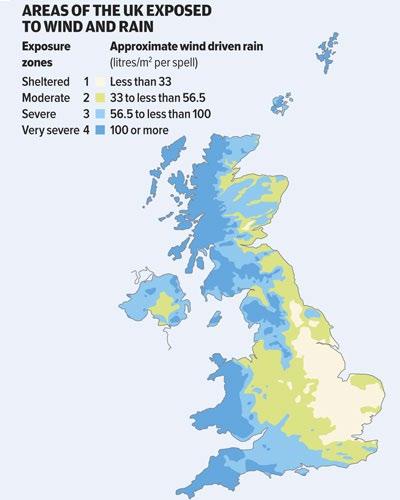
The building envelope must be designed to cope with temperature variation, wind, rain and snow. These forces can act in combination to produce severe effects, for example, wind-driven rain. The effect of the external environment on a building depends on its altitude, latitude and longitude. Figure 1.1 shows the considerations that will influence the impact of the external environment:
• number of storeys • building’s exposure • way in which architectural features provide shelter • complexity of the building envelope
Increasing risk Number of storeys Exposure to driving rain
Shelter provided by architectural features
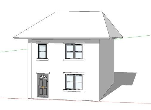

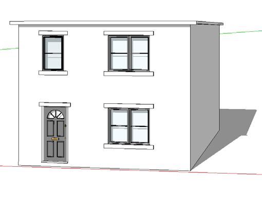
Envelope/cladding complexity
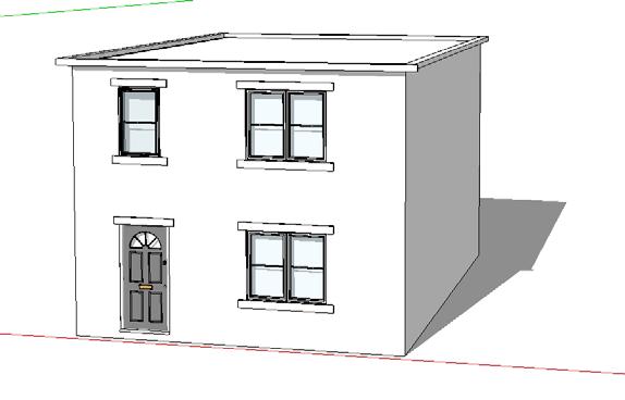
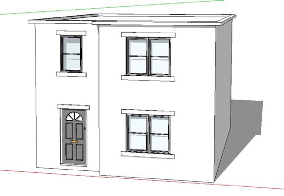
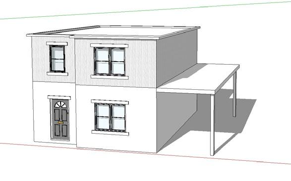
Figure 1.1 - Factors influencing the impact of the external environment
2.2 WATER
It has been estimated that 75% of building failures are due to water. These occur mainly through rain water penetration, but also interstitial condensation that occurs within the building fabric and surface condensation affects building finishes.
Water also affects the performance of the building in other ways, particularly in terms of thermal performance and the effect on human health. For example, damp external walls exhibit considerably lower thermal resistance, while surface condensation on the inside of houses causes moulds, which are not good for human health.
Water is attracted to hygroscopic materials (which have capillary pores) in both the liquid and vapour state. Liquid water is sucked into very small tubes, capillaries which are present in porous materials. The sucking, or wicking, of interconnected capillaries is what causes water to be drawn up into a brick for example, or into the end grain of timber. Hydrophobic materials, such as glass, steel and plastics, repel water, which causes water to bead, for example, rain on oil soaked concrete.
Liquid water tends to exist in large clusters, because of molecular attraction. When liquid water evaporates as its temperature increases, the clusters break up into their individual vapour molecules. The size difference between liquid water molecule clumps and lone water vapour molecules explains how materials such as GoreTex and breather membranes such as Nilvent, Spirtech and Tyvek can simultaneously be watertight and vapour permeable.
All buildings are made of relatively small components. Each joint between materials is a potential leak, and moisture has many ways to move through any gap in the structure:
• Gravity: water will naturally move downwards • Surface tension: causes water to cling to underside of a surface where it can run through into an opening • Capillary action: water can also move upwards - cracks or holes with smooth sides may act as capillaries and by mechanisms of surface tension, draw in water • Momentum: wind-driven rain possesses momentum that can move it through an opening • Pressure differential: water will move from areas of higher pressure to areas of lower pressure
Deflection is the first line of defence against moisture ingress. Driving rain can be minimised by good siting, plantings, landscaping and choice of building height. The shape of the roof and overhangs is important; by shadowing and redirecting airflow, as shown in Figure 1.4 hipped roofs provide the opportunity to shelter walls from rain on all four sides.
Figure 1.2 shows the forces leading to moisture ingress and Figure 1.3 how they can be neutralised (adapted from Lstiburek).
Forces Neutralised by Gravity Wash and overlap Surface tension Overhang and drip Capillary ac9on Capillary break Absorp9on Drain and weep Momentum Labrynth Air pressure differen9als Rainscreen assembly
Wash A slope on a horizontal surface to drain water away from vulnerable areas of a building eg. window or door sill, sloping roof, slopes to drain, pitch to drain, ground slope away from building Overlap A higher surface extended over a lower surface so water moved by the force of gravity cannot run behind or beneath them. Cannot be used on a level surface e.g. roof slates, ?mber cladding. Overhang and drip Water running down wall can be kept away from openings by crea?ng a projec?ng profile above the opening (overhang) and by crea?ng a con?nuous groove in the underside of the projec?on (drip) so that gravity will pull the adhering water free of the overhang e.g. door and window sills Capillary break Water can be pulled by capillary ac?on through a narrow crack; a capillary break is a crack/gap large enough so that a drop of water cannot bridge it e.g. cavity wall. Drain and weep Collect and conduct away water that may leak through the outer leaf e.g. cavity tray and weep hole Labrynth A joint in which a straight line cannot be constructed through it without passing through solid material Rainscreen A detail that blocks air currents passing through a joint to prevent water being pushed through by differen?al pressures e.g. ven?lated cavity
Figure 1.2 - Forces leading to moisture ingress
Figure 1.3 - Neutralising moisture ingress
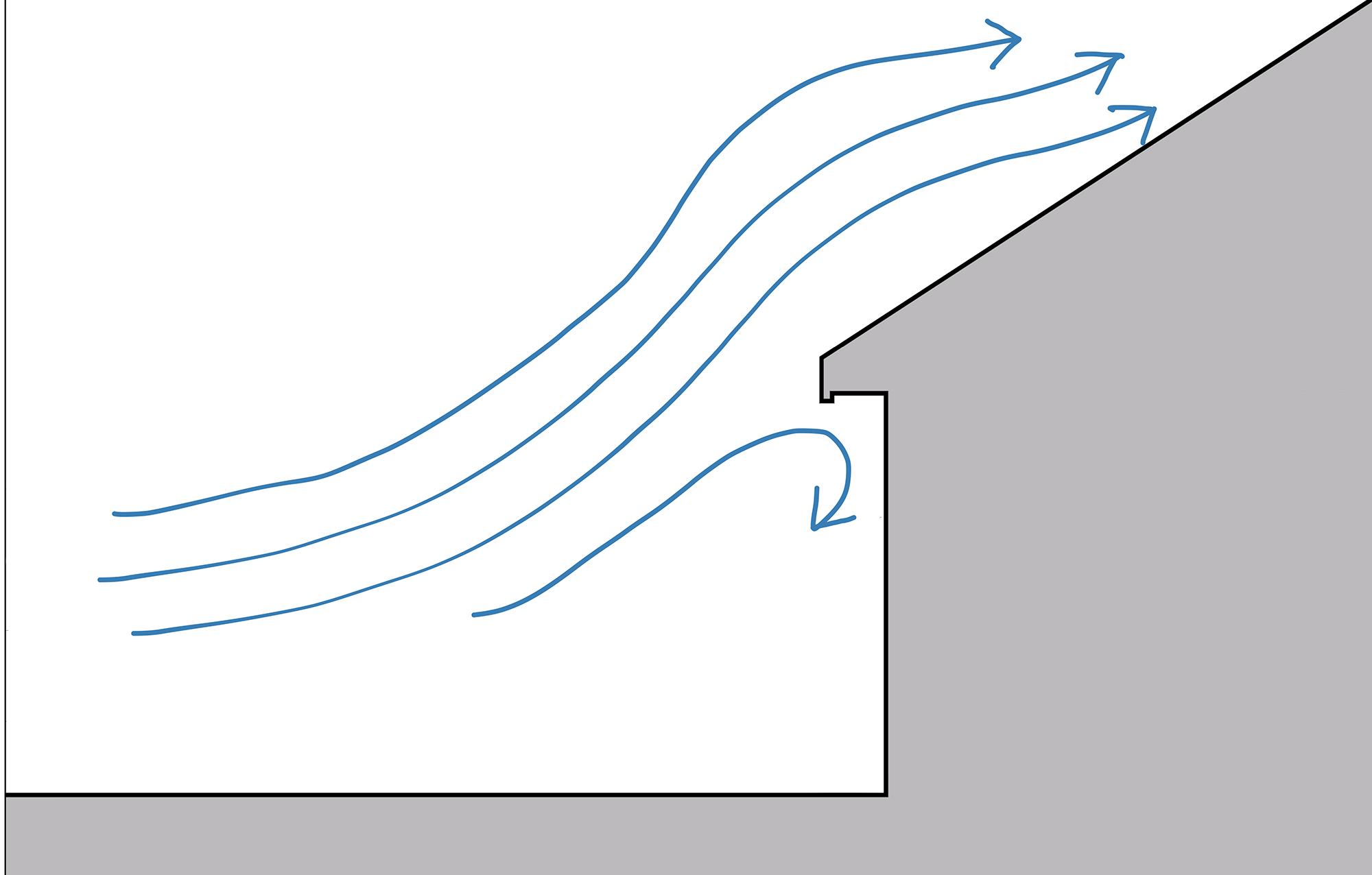
Figure 1.4 - Deflection of airflow with a pitched roof overhang
Once water is on the wall it will form a film and begin flowing downward under the force of gravity. Wind flowing over the surface will tend to deflect the flow from this path and may even force the water upward. Surface features such as trim (slopes and drip edges), surface texture and openings influence the flow paths, either concentrating or dispersing surface flows.
Siting, building shape and surface rainwater control rarely provide complete rain control therefore some strategy to deal with rainwater that penetrates the surface has to be used. There are three fundamental strategies, as outlined by Straube and Lstiburek:
• Mass walls: this requires the use of, for example solid masonry with enough storage mass and moisture tolerance to absorb all rainwater that is not drained or otherwise removed from the outer surface. This moisture is eventually removed by evaporative drying before it reaches the inner surface of the wall. A large mass of material is required to provide sufficient moisture storage. Examples include adobe, solid masonry. • Perfect barriers: stop all water penetration at a single plane e.g. some window frames, some metal and glass curtain walling systems. Some systems use factory built wall elements that are perfect barriers. The joints between them may also be designed as perfect barriers e.g. a single line of caulking/sealant. These are not very effective. • Screen-drained walls: this strategy assumes some rainwater will penetrate the outer surface and remove this water by designing an element that provides drainage within the wall e.g. cavity wall.
3 - CONSERVATION OF HEAT AND POWER
The requirement for buildings to be energy efficient is one of the key requirements imposed on designers and builders. The burning of fossil fuels to provide the energy to heat, cool and power buildings contributes nearly half the UK’s CO2 emissions. The Government is committed to reduce the UK’s greenhouse gas emissions by 80% by 2050 and reducing emissions from buildings is a key way of achieving this. Approved Document Part L of the Building Regulations is the vehicle by which the Government seeks to improve energy efficiency by reducing heat loss from buildings.
3.1 - HEAT LOSS
Heat is lost from buildings in two ways. It is lost through the fabric of the building (the building envelope) by radiation, convection and conduction exchanges. This is known as fabric heat loss. Buildings are not completely airtight and heat is also lost by heated air leaving the building through gaps in the building fabric and being replaced by colder air that needs to be heated. This is known as ventilation heat loss.
Total Heat Loss (Q) = Fabric Heat Loss (Qf) + Ventilation Heat Loss (Qv)
3.1.1 - FABRIC HEAT LOSS
The amount of heat that is lost through this route (Qf) depends on three things:
• The difference between the inside design temperature and the outside temperature (ΔT) • The area of the different building elements exposed to the temperature differential (A) • The rate at which heat flows through the different building elements exposed to the temperature differential, known as the U-value (U)
This can be represented as the equation:
Qf = Ʃ (U.A.ΔT) measured in Watts (Ʃ simply means ‘the sum of’)
The temperature differential and area of the building elements are straightforward, but the U-value is an important concept that needs further explanation.
3.1.2 - U-VALUES
A measure called a U-value, (also called the thermal transmittance coefficient) is the conventional way of expressing the rate at which heat flows through a building element such as an external wall, window, ground floor or roof. Its formal definition is:
The units in which the measure is expressed are therefore:
W/m2K
Watts per square metre per degree Kelvin (the formal SI unit of temperature: a change in temperature of 1K is the same as a change in temperature of 1oC).
The U-value is a measure of the rate at which a building element transmits heat. The higher the U-value, the more heat is transmitted, or lost, through the building element. From an energy conservation point of view therefore, the lower the U-value of a building element the better.
The Building Regulations specify maximum U-values that should not be exceeded for different building elements. Approved Document Part L 1A sets the ‘reasonable limits’ shown in Figure 1.5. In practice, compliance with the requirements of the Building Regulations to conserve heat and power mean that design U-values need to be much lower than these ‘reasonable limits’. The notional dwelling specification shown in the table represents the U-values that designers should be aiming to achieve.
Element Limi)ng U value (fabric elements of building) (W/m2K)
Wall 0.30
Floor Roof
0.25 0.20 Windows/Doors 2.00
Figure 1.5 - Table of U-values
3.1.3 - CALCULATING U-VALUES
No)onal dwelling specifica)on U value (W/m2K)
0.18 0.13 0.13 1.40
A U-value is a measure of thermal transmittance. Heat flow through a material is usually expressed in terms of thermal resistance (R). Transmittance is the inverse of resistance and can therefore be expressed as the reciprocal of resistance:
Thermal Transmittance (U-value) = 1 Thermal Resistance (R)
A building element is composed of a number of materials, each of which has a resistance to the flow of heat. The U-value of a building element can therefore be calculated by adding together the thermal resistances of the components of the building element (ƩR) and dividing the result into one (taking its reciprocal). The shorthand expression of that, and the formula for calculating a U-value (U) is:
U= 1 ƩR (Units W/m2K )
3.1.4 - THERMAL RESISTANCE
The amount of resistance that a material offers to the heat flow through it depends on the thermal properties of the material and its thickness. It can be calculated from the following formula:
R= d ʎ
R is the thermal resistance of a material (m2K/W) d is the thickness of the material (in metres) ʎ is the thermal conductivity of the material (W/mK)
3.1.5 - SURFACE AND AIRSPACE RESISTANCE
In a building element it is not only materials that provide a resistance to the transfer of heat; surfaces and airspaces or empty cavities also offer resistances that need to be taken into account in calculating U-values. These are usually standard values that can be found from tables such as those published by CIBSE.
3.1.6 - THERMAL CONDUCTIVITY
The thermal conductivity (ʎ) of a material is the heat flow in watts across a thickness of 1 square meter when the air temperature either side differs by one degree.
Materials which have a high thermal conductivity, such as copper, are good conductors of heat and therefore poor thermal insulators. Conversely, materials that have a low thermal conductivity, such as expanded polystyrene, are poor conductors of heat and therefore good thermal insulators. A table of the thermal conductivity of common construction materials is shown below.
Material Aluminium Steel (mild) Concrete (medium density) Tiles (clay) Brickwork Lightweight concrete block Plaster (dense) Plasterboard Aircrete block Timber Glass fibre insulaJon Thermal Conduc2vity (W/mK) 190.00 60.00 1.13 1.00 0.77 0.57 0.57 0.21 0.18 0.13 0.04
Figure 1.6 - Table of thermal conductivity of common construction materials
The thermal conductivity figures are based on measurements in controlled environments and make standard assumptions about, for example, moisture content. In practice, the moisture content of materials may be higher than assumed. If a material, such as mineral wool insulation, becomes wet then its thermal conductivity will be higher (because thermal conductivity of water is greater than that of air).
Calculation of a U-value for an external cavity wall The structure of the wall is shown in the diagram below along with information on the thermal conductivities of the materials and standard values for surface and air gap resistances. From this information, the thermal resistances of the components of the wall are calculated. These are then added to the resistances of the surfaces and air gap. The total resistance is then divided into one to determine the U-value.
Thermal conductivities (W/mK)
Dense plaster 0.50 Lightweight blockwork 0.11 Brickwork 0.84 Phenolic foam insulation 0.02
Surface and air gap resistances (m2K/W)
Internal surface External surface Air gap 0.12 0.06 0.18
Thickness Thermal Conduc2vity Thermal Resistance (d) (����) R=d/���� Internal Surface - - 0.120 Plaster 0.013 0.50 0.026 Blockwork 0.100 0.11 0.909 Insula2on 0.080 0.02 4.000 Air gap - - 0.180 Brickwork 0.102 0.84 0.121 External Surface - - 0.060
Total Resistance (ƩR) = 5.416
U-value = 1/ƩR = 1/5.416 = 0.18 W/m2K
Standard U-value calculations assume that the materials in the building element are homogeneous, in other words that the thermal resistance is constant in the plane of the material. In practice that is not always the case. There may be gaps in the layer of material, or the material may be ‘bridged’ in some way.
For example in a timber frame external wall construction, the timber studs interrupt, or bridge, the insulation layer in the framed wall. In a cold roof the ceiling joists interrupt the layer of insulation placed between the joists. In a cavity wall, a combined lintel bridges the cavity. These are all examples of thermal bridging.
A thermal bridge is created when materials that are poorer insulators than surrounding materials come in contact, allowing heat to flow through the path created. Thermal bridging has become a significant source of heat loss as insulation standards have improved and this has to be allowed for in estimating the heat loss from buildings.
3.2 - VENTILATION HEAT LOSS
Building fabric has improved over time to meet more stringent Building Regulation requirements, U-values have therefore declined and building fabric heat loss has decreased. There has been less regulatory concern with airtightness with the result that ventilation heat loss can now account for up to a third of total heat loss in a new dwelling.
The ventilation heat losses in a building are determined by:
• the volume of air passing through the building that requires heating to achieve the desired internal temperature (calculated by the number of air changes per hour multiplied by the volume of the building) • the amount of heat energy required to raise the air temperature by one degree (the specific heat capacity of air) • the difference between the temperature to which the inside of the building is designed to be heated and the temperature outside of the building
Ventilation heat loss can therefore be estimated using the following equation:
Qv = Cv.N.V.ΔT 3600
Qv is the ventilation heat loss (Watts)
Cv is the specific heat capacity of air - usually given as 1210 J/m3K
N is the number of air changes per hour (ach): divided by 3600 gives air changes per second, which is the correct unit as Qv is measured in Watts, or Joules per second
V is the volume of the building that is conditioned, or heated
ΔT is the difference in temperature between the inside and outside of the building
The recommended ventilation requirements for UK dwellings are between 0.5ach and 1.0ach.
3.3 - HEAT LOSS: THEORY AND PRACTICE
The above equations are only an approximation of what is called ‘steady state’ heat transfer, in which variables such as temperature differential do not change. Such formulations cannot provide a dynamic picture of heat transfer over time, which would be necessary to assess for example, whether summer overheating is likely to occur. To do this, much more complicated dynamic models are required.
Furthermore, thermal models tend to seriously underestimate actual heat loss from a building. Research carried out by Leeds Beckett University has shown that a significant discrepancy exists between the energy performance of a dwelling as designed and that realised in practice, typically around 20% higher than predicted by modelling. The difference between measured and predicted performance can be accounted for by factors such as:
• Thermal bypasses. A thermal bypass is set up whenever air movement is able to take place in such a way as to reduce the effectiveness of an insulation layer, for example via the party wall cavity or if insulation boards in a cavity wall are not butted firmly up to the blockwork. • Higher than predicted thermal bridging, for example as a result of the timber fraction in a timber frame wall being significantly higher than the nominal value. • Real fabric U-values higher than nominal, for example installing windows who ‘centre page’ U-values equate to the design U-value but whose ‘whole window’ U-value is significantly higher. Another example would be where components such as insulation become damp, resulting in higher heat loss than predicted using manufacturer’s data on thermal conductivity in laboratory conditions. • As-built differing from design intent. This can happen in relation to the fabric in many ways, for example the omission of a perimeter insulation detail. It can also happen in relation to airtightness, for example service penetrations not being properly sealed.
4 - AIRFLOW AND VENTILATION
Ventilation is dealt with in Approved Document Part F of the Building Regulations. The requirement is that there should be adequate means of ventilation provided. The ventilation system should:
• extract water vapour from areas with high rates of generation (e.g. kitchens, utility rooms and bathrooms) before it can spread widely; • extract hazardous pollutants from areas where they are produced in significant quantities, before they can spread widely; • rapidly dilute pollutants and water vapour in habitable rooms, occupiable rooms and sanitary accommodation; • provide a minimum supply of outdoor air for occupants and disperse residual pollutants and water vapour; • perform in a way which is not detrimental to the health of people in the building;
The control of airflow is important for several reasons: to control moisture damage, reduce energy losses, and ensure occupier comfort and health.
• Moisture control: water vapour in the air can be deposited within the building envelope by condensation and cause health, durability and performance problems. • Energy savings: warmed air leading out of a building is replaced by (usually) colder air which requires energy to heat it - about a third of space heating energy consumption is due to air leakage through the building enclosure. • Comfort and health: cold draughts and excessively dry wintertime air that result from excessive air leakage directly affect human comfort, airborne sound transmission control requires good airflow control and external odours and gases can cause health and comfort problems.
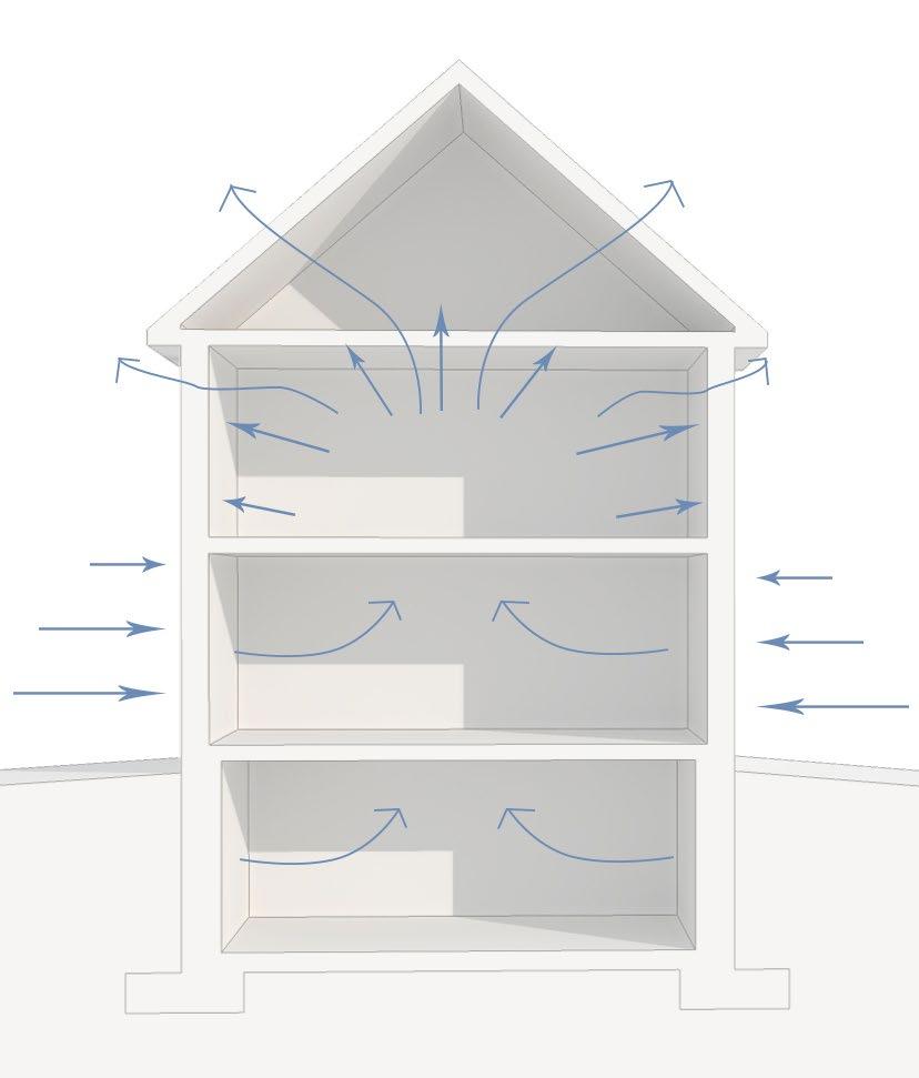
Airflow across buildings is driven by wind pressures, stack effects, and mechanical air handling equipment such as fans, illustrated in Figure 1.7. A continuous, stiff, durable, air permeable barrier system is required between the external and internal space to control airflow driven by these forces. Uncontrolled air leakage through the building envelope is a major cause of building performance problems.
Increased airtightness must be matched by an appropriate ventilation system to dilute pollutants, provide fresh air and control humidity levels.
Typical leakage paths through the building envelope are shown in Figure 1.8 below.
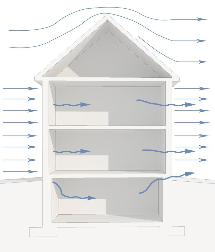
Wind effect
Stack effect Figure 1.7 - Forces driving airflow through the building enclosure

Combustion and ventilation
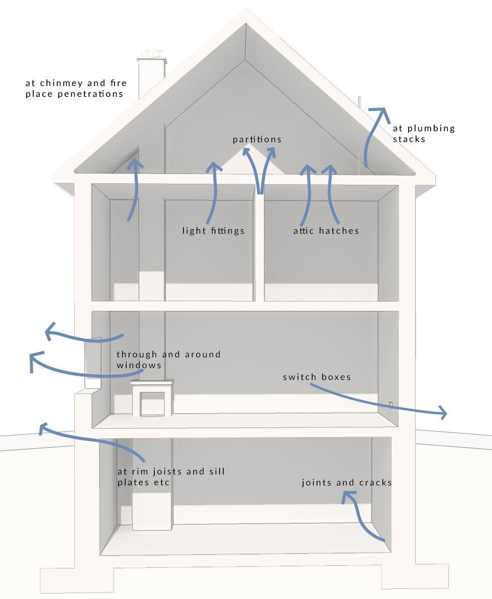
For airflow to occur there must be both: • A pressure difference between two points, and • A continuous flow path or opening connecting the points
The general approach taken to control airflow is to attempt to seal all openings at one plane in the building enclosure. The primary plane of airtightness is called the air barrier system: an assembly of materials including every joint, seam and penetration.
Winds pressure effects (see Figure 1.9 below). Low slope roofs tend to have mostly negative (uplift) pressures, especially on the leading edge. Roofs with slopes above 25o degrees experience positive pressures on the windward face and suctions on the leeward.
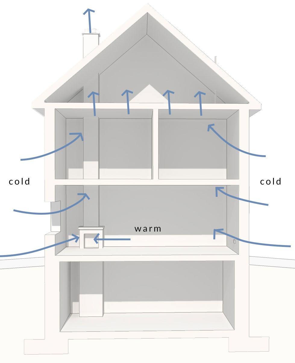
Stack effect pressures (see Figure 1.10 below) are generated by variations in air density with temperature. The density of warm air is less than that of cold air. Therefore hot air rises and cold air sinks. In a building, during winter, as heated air rises it ‘sucks in’ colder air from outside.
Bathroom exhaust fans, clothes dryers, cooker hoods all exhaust air from a building. This creates a negative pressure inside the building that can cause inward air leakage through the building enclosure.
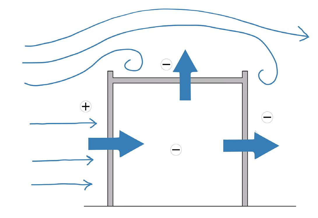
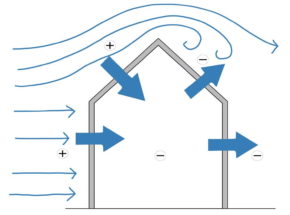
Figure 1.9- Wind pressure effects
Figure 1.10- Stack effect pressures
It is generally accepted that pollutants, such as dust mites, pet allergens, pollen, moulds, fungi, bacteria and viruses are increasing in buildings and have an increasingly negative impact on human health, such as the prevalence of asthma. Some are introduced by occupants or are brought in from the outside. However, many are a result of the built environment itself, and in the main are due to environmental conditions of humidity and temperature that have only been experienced in buildings in the very recent past.
All these pollutants generally require very high levels of humidity to thrive. They cannot thrive, if relative humidity is kept between 40% and 60%. In addition, other chemical reactions such as those involving VOCs, are more dangerous to the human body as humidity levels rise, particularly at levels over 70% RH. At levels under 40% human mucus membranes become dry and more vulnerable to irritation from chemical pollutants and small particles. People become much more sensitive to odours at low RH levels, and people wearing contact lenses can suffer irritation. Under 35% RH the effect of static on the human body is considerable both internally and externally. For example external static shocks from walking on nylon carpets can be as high as 35,000 volts at low RH levels. Increasing RH to above 35% would automatically reduce the potential of static shock to 1,500 volts or less.
5 - ACOUSTICS
In addition to temperature and humidity, acoustic isolation is also important for comfort. As a result of the growing number of complaints about domestic noise disturbance and the potential litigation arising from these, Building Regulations have considerably improved acoustic insulation requirements since 2002.
There are a number of issues in relation to acoustics in buildings: • sound insulation • between dwellings • between rooms in a building • reverberation in rooms • internal noise levels from building services • outside noises • noise emitted from the building
Approved Document Part E is intended to reduce the transmission of sound into, and between the rooms of residential buildings. The requirements are that dwellings, flats and rooms for residential purposes shall be designed and constructed in such a way that:
• they provide reasonable resistance to sound from other parts of the same building and from adjoining buildings; and • that (a) internal walls between a bedroom or a room containing a WC, and other rooms; and (b) internal floors, provide reasonable resistance to sound
6 - LIGHT
Lighting in the indoor environment has three basic purposes: to enable the occupants to work and move about in safety; to enable tasks to be performed, and to make the interior look pleasant.
Buildings can be lit either naturally, by daylight received from the sky, or artificially - by electric lamps or other artificial light sources.
The quantity and quality of natural light in an interior depends on the external environment (site layout and planning) and the internal environment (size and positioning of windows, depth and shape of rooms). The primary reference in the UK for daylighting criteria is BS8206: Lighting for buildings: Part 2: Code of practice for daylighting, which treats daylight as two distinct sources of light:
• Sunlight - That part of solar radiation that reaches the earth’s surface as parallel rays after selective attenuation by the atmosphere • Skylight - That part of solar radiation that reaches the earth’s surface as a result of scattering in the atmosphere.
Sunlight and skylight may therefore be considered as the direct and diffuse components of daylight.
Interior daylight is measured by the Daylight Factor (DF).
Daylight factor is defined as:
Daylight Factor (%) = Interior Illuminance x 100 Simultaneous horizontal unobstructed exterior illuminance
The Daylight Factor is a combination of three components: • The sky component (SC) - the light received directly from the sky. • The externally reflected component (ERC) - the light received directly by reflection from buildings and obstructions outside the room. • The internally reflected component (IRC) - the light received from surfaces inside the room.
Estimates for the SC and ERC can be obtained from a number of sources, including: BRE Daylight Protractors, BRE Simplified Daylight Tables, Waldrum Diagrams, Fuller Moore Dot Charts. The IRC can be obtained from tabulated data.
Understanding artificial lighting requires the use of a number of terms: • Luminous flux (F) - the amount of light emitted by a light source. Measured in lumens (lm). • Luminous efficacy – a measure of how effectively a lamp transforms electricity into light or luminous flux: the luminous efficacy is the lamp light output in lumens per watt of electrical power consumption, (lm/W). • Luminous intensity (I) - is the power of a light source, or illuminated surface, to emit light in a particular direction. Measured in candelas (cd). • Illuminance (E) - the luminous flux density (spread of light) at a surface measured in lux (lx), where 1 lux = 1 lm/m2. A common minimum level for working is 200 lx, but in bright sunlight it can reach 50000lx. • Luminance (L) - this is a measure of the ability of an area of light source, or reflecting surface, to produce the sensation of brightness. • Colour rendering - this is the ability of a lamp to reveal the colour of a surface, compared to the colour of the surface viewed in daylight: a measure of how accurately the colour of surfaces appears under different light sources. It is expressed by a colour rendering index (Ra) of up to 100. An Ra of between 80-89 is considered very good, while one between 90-100 is regarded as excellent. • Colour temperature - gives an indication of the appearance of the light. Lower colour temperatures mean a ‘warmer’ appearance. Early fluorescent lamps had a high colour temperature giving a very ‘cold’ appearance; but now a wide range of colour temperatures is available, including some that are similar to incandescent lamps. 7 - FIRE
Approved Document Part B1, Volume 1 - Dwellinghouses, defines the key aspects of fire safety in the construction of buildings. Some of these are: • The building shall have a means of early warning and escape in the event of a fire. • The internal spread of fire should be inhibited within the building by ensuring linings adequately resist the spread of flame over their surface. • The building shall be designed and constructed so that its stability will be maintained for a reasonable period in the event of a fire. • Walls common to two or more dwellings are to adequately resist spread of fire between those buildings. • Unseen spread of fire and smoke within a concealed space within the structure must be inhibited. • External walls and roofs of a building are able to resist spread of fire from one building to another.
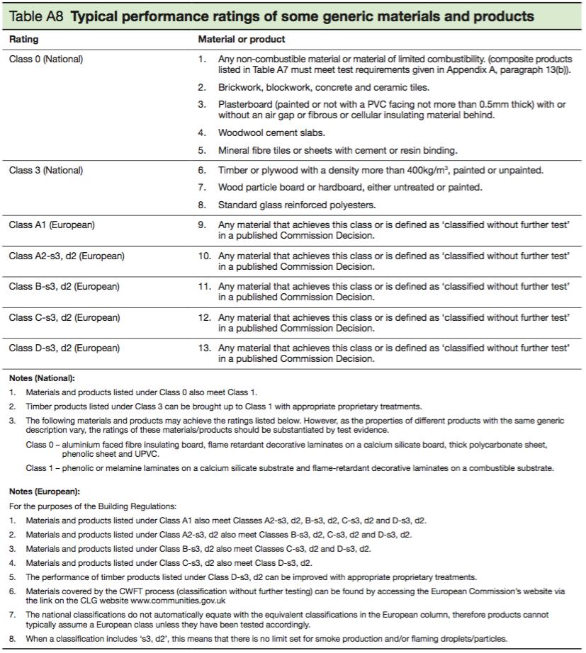
Although it is preferable to build new structures with non combustible materials, that is not always feasible. Many of the structural elements are combustible in some way, but we have developed suitable understanding and methods to allow use of these materials in a safe and effective manner. Timber, for example is a combustible material, but if a structural element is specified with sufficient thickness the rate of combustion of any excess timber should provide sufficient time for the building to be evacuated in the event of a fire. Masonry construction materials tend to have a good fire resistance, due to their manufacturing process being at high temperatures. Concrete however, does suffer damage in a fire is natural aggregates are used.
Steel can demonstrate a loss of strength in temperatures over 500 degrees, and it is often treated with a fire retardant coating, or covered with a material that has good fire resistance in order to protect it from fire.
7.2 NON STRUCTURAL ELEMENTS
Internal and external finishes to a building also have an important bearing on fire resistance of an overall structure. It is key that any surfaces do not encourage the spread of fire and have a low rate of heat release or fire growth if ignited.
7.3 FIRE PROTECTION
7.3.1 EXTERNAL WALLS
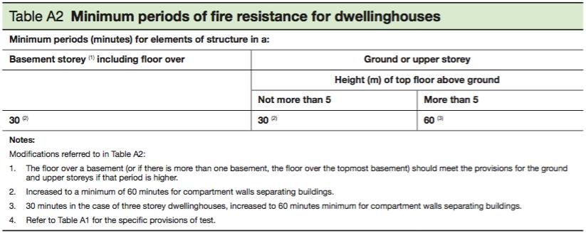
The regulations state that external walls of a dwelling must provide suitable fire resistance for the building and retain its structural stability for a period to allow occupants to escape. It is recommended that dwellings with a top floor within 5m of ground level require 30mins fire resistance, while any houses above this level require 60mins fire resistance. Any wall to an adjoining property must have 60mins fire resistance, regardless of height.
7.3.2 FLOORS
Any floor must resist collapse for a sufficient period of time in order to allow occupants to escape in the event of a fire. The regulations state that floors within 5m of ground level have 30mins fire resistance, and any floors above 5m have 60mins fire resistance.
7.3.3 CAVITY BARRIERS
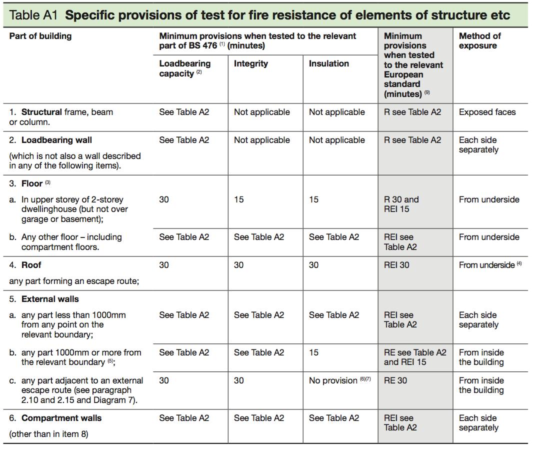
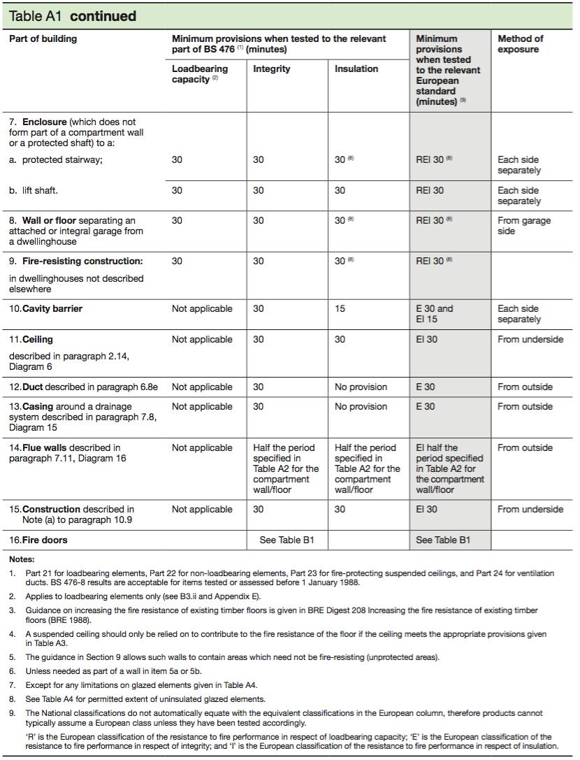
In order to restrict spread of fire or smoke in concealed places within the structure, the building regulations require any cavities in timber structures to be closed with a cavity barrier. A cavity barrier is capable of providing fire resistance of at least 30mins, and are generally a polythene sleeved mineral wool. The barriers are required at openings, roof verges and eaves and party wall lines.
Fire stops are also required at the junction of any separating wall, the external wall at the junction of separating wall and roof in any terraced or semi detached house. These are made of a non combustible material, usually a wire reinforced mineral wool quilt.
7.3.4 PROTECTING OPENINGS
Any openings should be protected by sealing or fire stopping in order to maintain the effectiveness of fire separating elements. Not only does fire stopping and sealing delay the passage of fire, it also can retard the spread of smoke.
Table A1, A2 and A8 demonstrate some of the requirements set out in Approved Document Part B Volume 1. Table A1 gives requirements for each element in terms of one or more of the following criteria: • Resistance to collapse • Resistance to fire penetration • Resistance to the transfer of excessive heat
