25 minute read
MASONRY CONSTRUCTION
FLOORS
The most common materials used for the construction of ground and upper floors tend to be concrete or timber. Required span, resistance to passage of sound, and fire resistance will often be factors to consider when deciding which material to use in floor design.
Advertisement
FUNCTIONAL REQUIREMENTS
The functional requirements of a floor are: • Strength and stability • Resistance to weather and ground moisture • Durability • Fire safety • Resistance to passage of heat • Resistance to passage of sound
TYPES OF GROUND FLOORS
CONCRETE FLOORS
There are two types of concrete floor system commonly used in residential construction; ground bearing and suspended. Ground bearing floors, where the concrete slab is supported by the ground below. Suspended concrete floors do not rely on the ground below, but instead are supported by the external walls and therefore the foundations below. In this section we will look at both types of concrete floor.
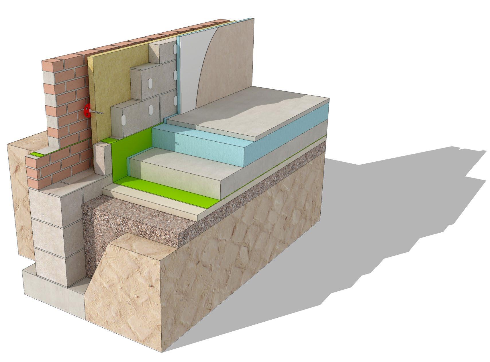
Ground Bearing Concrete Floor The ground bearing concrete floor slab is supported by the load bearing strata below. The slab abuts but is not tied to the external walls. The build up of this type of system can typically be: • Hardcore fill to compacted to create suitable level (approx 200mm thick) • Damp proof membrane (DPM), often laid over sand binding • Rigid floor insulation (can be position above or below the concrete slab) • Concrete floor cast in situ • Floor screed if required, followed by floor finishes
There are many different options for positioning of damp proof membrane and insulation which can be seen in the following details in this section.
Suspended Concrete Floor Suspended concrete floors have become popular in UK house construction. They are typically used in situations such as sloping sites, the ground has poor bearing capacity, or there is likelihood of ground volume change. Suspended floors are also used when the water table is high, or when aggressive chemicals are present in the soil that may attack the concrete slab.
The ground floor is made up of suspended concrete slab or beam and block floor, supported by the external and internal load bearing walls, which transfer the loads to the foundations below. Both pre-cast concrete planks or slabs can be used, as well as cast in situ reinforced slabs along with beam and block systems.
Beam and block These systems use concrete T beams that span between the walls, concrete infill blocks are then inserted between the beams to provide a solid base for the concrete topping or screed that is spread and levelled over the concrete units. Depth of the beams is between 130mm and 250mm and is determined by the span required, and the loads to be supported.
Figure 5.2 - Beam and block floor Damp Proof Membrane (DPM) Concrete is not impervious to water and it is therefore necessary to protect the floor with a water resistant barrier to prevent moisture penetrating the building from the ground. This barrier is a damp proof membrane usually in the form of a thin sheet of polythene or polyethylene, although bitumen in various forms can also be used.
The membrane position varies according to the type of floor construction selected. If the membrane is positioned below the concrete slab, it is placed over the hardcore on a sand blinding to protect it from damage. The edges of the membrane are turned up the sides of the external walls so that it overlaps the damp proof course. When using rigid, impermeable insulation, it is prudent to use a vapour control layer on the warm side of the insulation (or position DPM on warm side of insulation) to minimise the possibility of interstitial condensation. While concrete does offer a good level of natural resistance, poor workmanship can sometimes result in the passing of vapour through the structure. Likewise, if a timber floor is being used, it is important to install a vapour control layer under the timber floor.
Damp Proof Course (DPC)
A DPC acts as a barrier to the passage of moisture into the structure, be it upwards in wall foundations, downwards in a parapet or horizontally in a window jamb. Generally made from dense polythene, the DPC should not penetrate the cavity, unless weep holes are provided that can direct water away from the cavity. In a traditional masonry cavity wall the DPC is laid in two separate strips, one internal and one on the external leaf, 150mm minimum above external ground level. The DPC should be lapped with the DPM to provide a good joint and prevent moisture tracking between them.

TIMBER FLOORS
Although timber ground floor construction used to be a popular method, today it is not as common as the concrete alternatives. A suspended timber floor is constructed as a timber platform of boards nailed across timber joists supported on sleeper walls, and the external and internal load bearing walls surrounding them.
Ventilation must be provided throughout the underfloor void and through any sleeper walls with cross ventilation. Due to airtightness, acoustic and sometimes structural requirements of the Building Regulations, joist ends tend to be supported by joist hangers rather than being built into external or sleeper walls.
The floor is insulated in the form of rigid insulation between joists, or quilt between joists supported by netting. Floorboards are fixed over the floor joists and insulation, usually in the form of plywood, chipboard or OSB to required structural performance. These boards are then applied with a floor finish, such as carpet, vinyl and so on.
UPPER FLOORS
TIMBER UPPER FLOORS
Timber has traditionally been the material of choice for upper floor construction. Nowadays, there are suitable
alternatives in steel and concrete, however, these are seen more in commercial buildings or residential flats. It is still most common to see timber upper floors in domestic house construction.
Upper floor construction tends to consist of a series of timber joists or beams covered with timber floorboards, or more commonly sheets of chipboard. The size of the joists depend on the span and expected loading. The joists are supported by the external walls on joist hangers or built into the internal leaf, and internal load bearing walls, but also act as a restraint for the external walls.
In order to prevent twisting or warping in the joists, it is sometimes common to find a line of strutting fixed at right angles to the joists. This strutting can reduce bounce in the floor.
More recent additions to timber floor construction are the timber I beams or metal web joists. These engineered joists can span greater distances than traditional timber cut joists and reduce the requirement of internal load bearing walls. The web joists also have the added benefit of not requiring notching or drilling for

Figure 5.3 - I beams and web joists
The Building Regulations require a minimum performance standard of acoustic insulation for floors to bedrooms, bathrooms and other rooms containing a WC. Likewise, upper floors over an unheated area of the dwelling, such as a garage, require the same insulation standard as that of a ground floor.
CONCRETE UPPER FLOORS
As mentioned previously, timber upper floors are still widely used in domestic construction today. However, in recent years some new build houses have been constructed using concrete upper floors, usually as beam and block or plank floors.
This form of concrete pre cast floor is very similar to the ground floor version mentioned earlier in this chapter. When the external walls have been built to the correct level, the pre-cast beams are lifted into position supported at either end by the internal skin of the cavity wall. As with the ground floor, once the beams are in position, the concrete blocks are placed between the beams to provide a base for the cast in situ concrete topping.
Pre-cast plank floors are also used in upper floor construction, and are also supported by the internal leaf of the cavity wall.
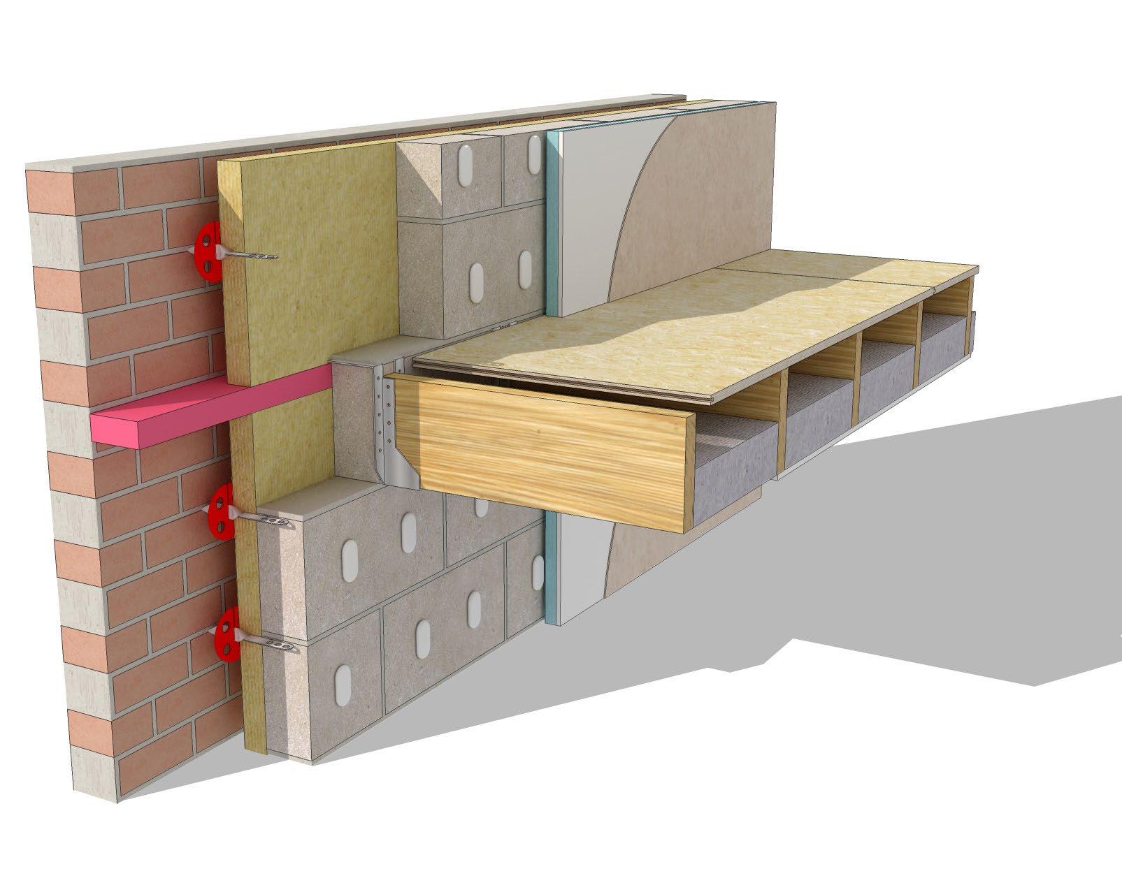
WALLS
The main function of an external wall is to provide shelter against the weather and fluctuations of outside temperature. The wall requires sufficient strength to support loads from upper floors and the roof. The majority of walls are constructed with load bearing masonry walls, or are a framed construction with timber, steel or concrete. On a domestic building, masonry and timber frame are most common and shall be the focus of this book.
FUNCTIONAL REQUIREMENTS
The functional requirements of the external wall are: • Strength and stability • Resistance to weather and ground moisture • Durability • Fire safety • Resistance to the passage of heat • Acoustic control • Security • Aesthetics
A standard cavity wall consists of an outer leaf of facing brickwork, a cavity (usually 100mm) with full or partial fill insulation, with an inner leaf of blockwork. There are of course many variations to this dependent on U-value requirements, internal and external finishes, structural loading and so on. The outer leaf and the cavity serve to resist the penetration of rain to the inside face, the inner leaf supports the floors and provides a solid internal wall surface.
The Building Regulations Approved Document Part A accepts a cavity of 50-100mm for cavity walls with leaves at least 90mm thick, built of coursed brickwork or blockwork with wall ties spaced at 450mm vertically and from 900 to 750mm horizontally.
WALL TIES
Wall ties do exactly as they say, they tie the wall together. They are positioned at intervals and can often be used as a fixing aid for insulation within the cavity. Early versions of the wall tie saw issues with moisture, where the ties provided a passage for water, and also a thermal bridge. Another issue with the wall tie is that they can collect mortar droppings as the outer leaf is being built which again cause issues with thermal bridging and moisture penetration. Now, wall ties usually have a twist or a drip, to prevent any moisture from reaching the inner leaf, and instead dripping down the cavity and out through weep holes. The ties are generally made from plastic or galvanised wire, and are as thin as possible to avoid collecting mortar droppings.
INSULATING THE WALL
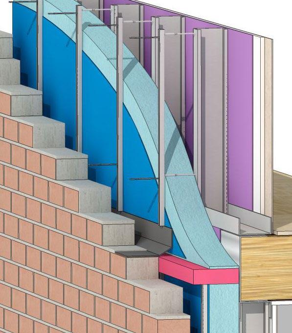
Cavity insulation boards are generally rigid and fixed to the inner leaf of the cavity wall. They are fixed with plastic washers that are clipped to the wall ties. The cavity can be partially filled or completely filled by the insulation boards.
A partial fill cavity secures the insulation to the inner leaf, leaving a 50mm air gap between the insulation and the outer leaf of the cavity. The installations boards are secured in place by clips that fix onto the wall ties.
A full fill cavity is where the insulation is built in as the walls are constructed, and as it suggests, completely fills the cavity. Semi rigid batts or slabs are used to maintain a vertical layer within the cavity.
Additional insulation can be provided on the internal leaf of the wall in the form of insulated plasterboard, or insulation between battens.
SOUND INSULATION AND PARTY WALLS
The Building Regulations recommend minimum performance standards of walls between two dwellings, i.e. party walls. This can be achieved by using dense blocks or brickwork in either a 215mm solid wall or 250mm cavity wall. It is important to seal cavities in party walls in order to reduce flanking sand and reduce air circulation within the cavity. Cavity barriers are used not only for this purpose, but also to withhold the passage of smoke and fire. Party walls must also achieve a minimum U-value of 0.2W/m2K.
DAMP PROOF COURSE
The Building Regulations stipulate that the wall should adequately resist the passage of moisture to the inside of the building. Moisture may penetrate the wall by absorption of water from the ground and therefore it is key to use a damp proof course. The damp proof course will prevent water rising through the wall and floors. Moisture can also move downwards in parapets and chimneys or horizontally at junctions of openings like windows and doors.
It is important that the damp proof course laps with the damp proof membrane to ensure good continuity between the two and to avoid moisture penetration. The DPC must be at least 150mm above finished ground level.
OPENINGS
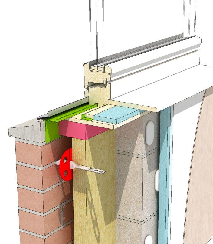
Approved Document Part A states that the number, size and position of openings should not impair the stability of a wall, it provides detailed requirements limiting the size of openings and recesses. When designing openings it is good practice to use cavity closers, or DPCs backed with insulation to avoid cold bridging at the reveal. Door and window frames are set in position to overlap the outer leaf with a resilient mastic pointing as a barrier to rain penetration between the frame and the jamb.
The function of the cill is to protect the wall below a window, so they are shaped to slope out and project beyond the external face of the wall in order to allow water to run off. It is good practice for the cill to project at least 45mm beyond the face of the wall below and have a drip on the underside of the projection.
At the head of an opening the brickwork or blockwork requires support by a lintel. Steel section lintels are often used, they are a galvanised strip that also act as a damp proof tray, or can be dressed with damp proofing material. The lintel is filled with EPS insulation to reduce thermal bridging. However, given the steel lintel spans between the inner and outer leaf of the cavity wall, there is still heat flow through the material. A more effective lintel arrangement that can further limit cold bridging is two independent concrete lintels.
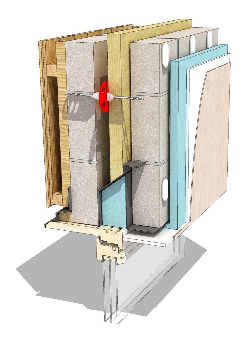
Figure 5.4 - Insulated lintel
CAVITY TRAYS
Some lintels have an integral cavity trays while others need a separate cavity tray which is usually formed using DPC materials on site. The cavity tray sits directly above the lintel, or sometimes a couple of courses above it. Any moisture trapped inside the cavity will be caught by the cavity tray and directed to the weep holes and out to the external face of the wall.
ROOFS
The roof is a key element of the building structure, providing protection from the elements and has a vital role in reducing heat loss from the building. Roofs tend to be either pitched or flat, and typically in residential construction, timber is the most common material used.
FUNCTIONAL REQUIREMENTS
The functional requirements of the roof are: • Strength and stability • Protection from the weather • Durability • Resistance to passage of sound • Thermal insulation • Resistance to air leakage • Fire safety • Security • Aesthetics
PITCHED ROOF
The majority of residential houses in the UK are constructed with pitched roofs. These pitched roofs are often constructed as a symmetrical roof with equal slopes that meet at a central ridge. Roof covering materials often determine the angle of the pitch, being the minimum slope that is necessary to prevent rain and snow ingress.
There are quite a few different types of pitch roof construction, some of which we will briefly explore in the next section.
Rake Ridge
Dormer
Valley Ridge
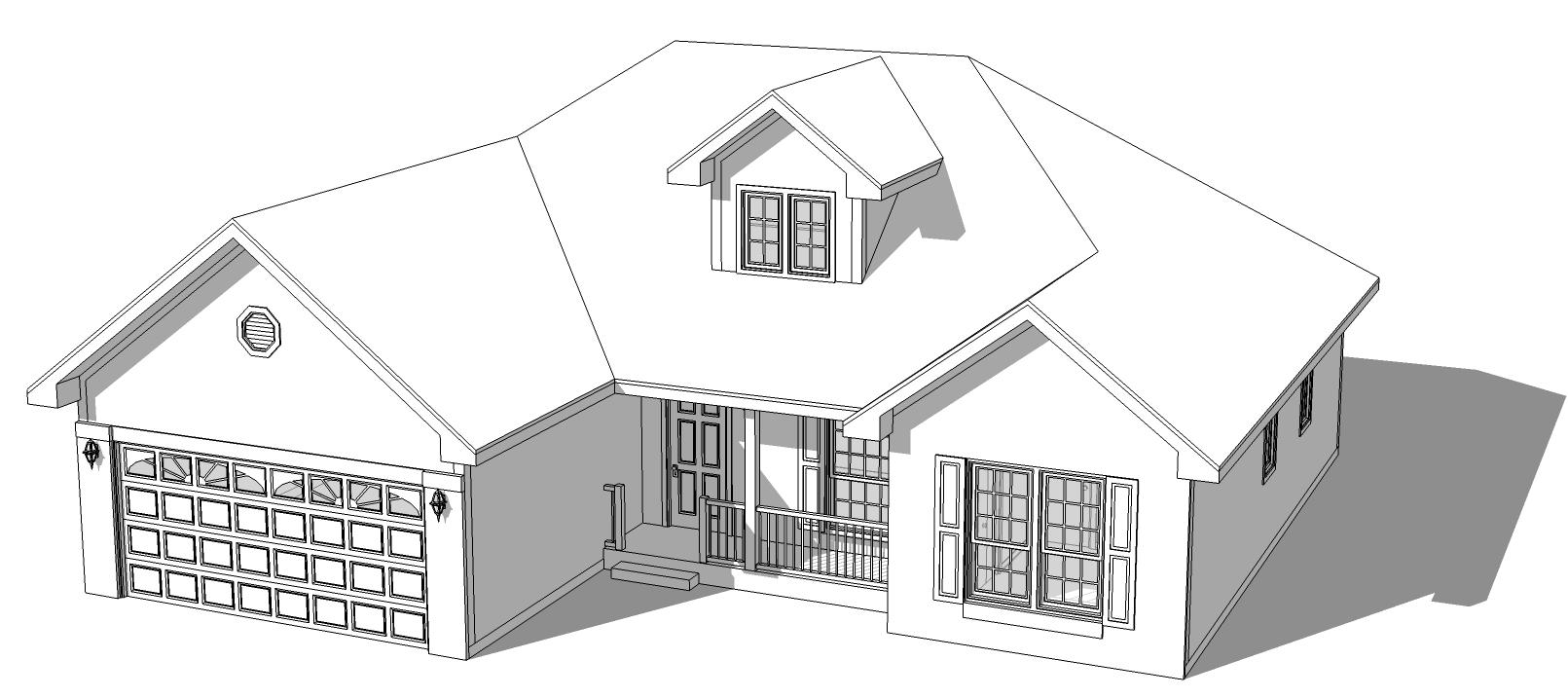
Hip
Field of roof
Eaves
Gable end
Figure 5.5 - Parts of a roof
SINGLE PITCHED ROOFS
Mono Pitch Roof - the simplest form of pitched roof, sometimes referred to as the lean-to. The foot of the rafters generally sit on a timber wall plate, that is fixed to the top of supporting wall. The top of the rafters are supported on a timber plate that is fixed to the supporting wall. The mono pitched roof has a limited span, therefore the double pitched roof is a more popular option.
DOUBLE PITCHED ROOFS
Couple Roof - simple pitched roof structure, consisting of timber rafters pitched up from the walls that support them, to a central ridge. A central ridge board is used to fix the rafters each side. This form of roof is often seen in farm buildings, stores and more simple structures. The maximum span of this roof is 3.5m, wider spans than this can cause the foot of the rafters to push the supporting walls outwards. Rafters are spaced at 400-600mm intervals, sizes are calculated according to span and support required for the roof covering. The ridge board is a continuous softwood board, usually 32mm thick. The foot of each rafter is fixed to the timber wall plate, which is fixed to the top of the wall to provide a level fixing surface. The wall plate tends to be 100x75mm, it serves to spread the load of the rafters along the wall. A notch (or birds mouth) is cut into the rafters at the foot, so the rafter can fit tightly onto the wall plate.
Close Couple Roof - construction very similar to the couple roof, but in this instance horizontal ceiling joists are nailed to the foot of each pair of rafters. This serves as a tie to resist the tendency for the rafters to push the walls outwards, but also serves as support for ceiling finishes. This type of roof is seen in small houses and bungalows. The ceiling joists can be 38-50mm thick, and a depth can range from 98mm to 220mm depending on span requirements and centres of the joists. These joists can provide roof space for services storage, such as water storage cisterns, along with general attic storage. The close couple roof tends to have a maximum span of 5.5m.

Figure 5.6 - Couple roof and close couple roof
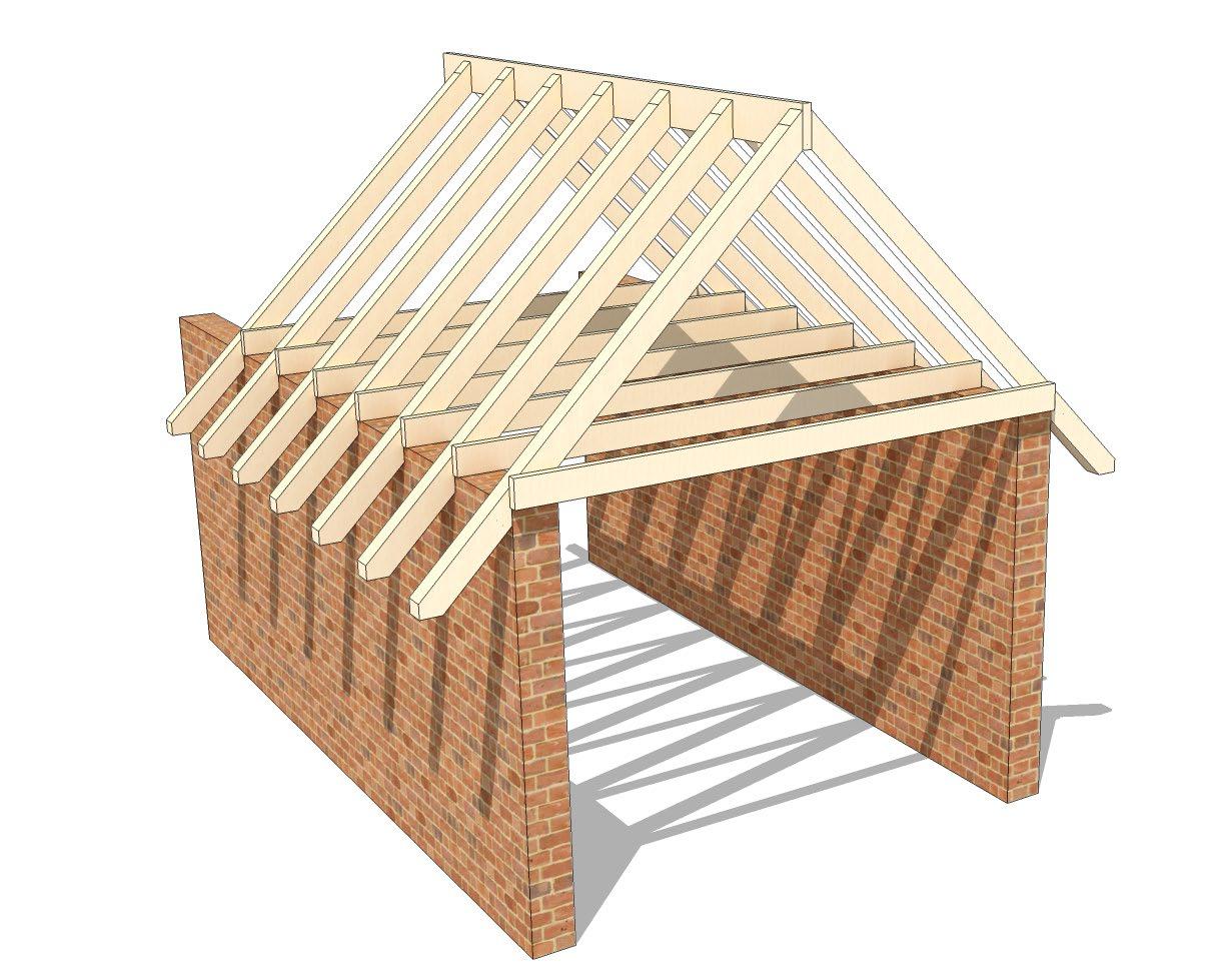
Collar Roof - similar to the close couple roof, rafters are framed by collars one third up the height of the roof. This opens up some of the roof to the first floor rooms, whilst providing support to the rafters. This system is often integrated with dormer window arrangements in order to maximise light penetration into the room. Providing support to the rafters a third of the way up the roof, is not as structurally effective as support at the foot of the rafters as described in the close couple roof. The collar roof tends to have a maximum span of 4.5m.
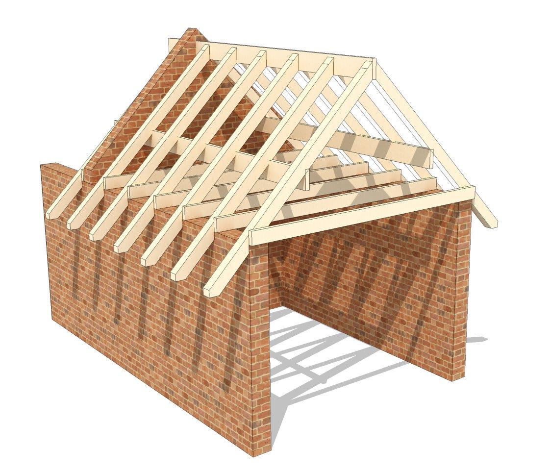
Purlin Roof - Purlins are horizontal timbers that are supported by end walls or struts to internal load bearing walls, that offer support to the rafters, thus enabling a reduced rafter section. The overall clear span of the rafter is reduced by half, therefore making a large saving in required rafter size. Purlins supported by gable end walls sit on masonry corbels projecting from the wall, or on joist hangers. If there is no gable end support, the purlins can be supported by the internal load bearing walls, using support struts between the wall and the rafters.
Guidance of rafter spacing, spans and sizes can be found in the Building Regulations Approved Document Part A and also the TRADA document “Eurocode span tables for solid timber members in floors, ceilings and roofs for dwellings”.
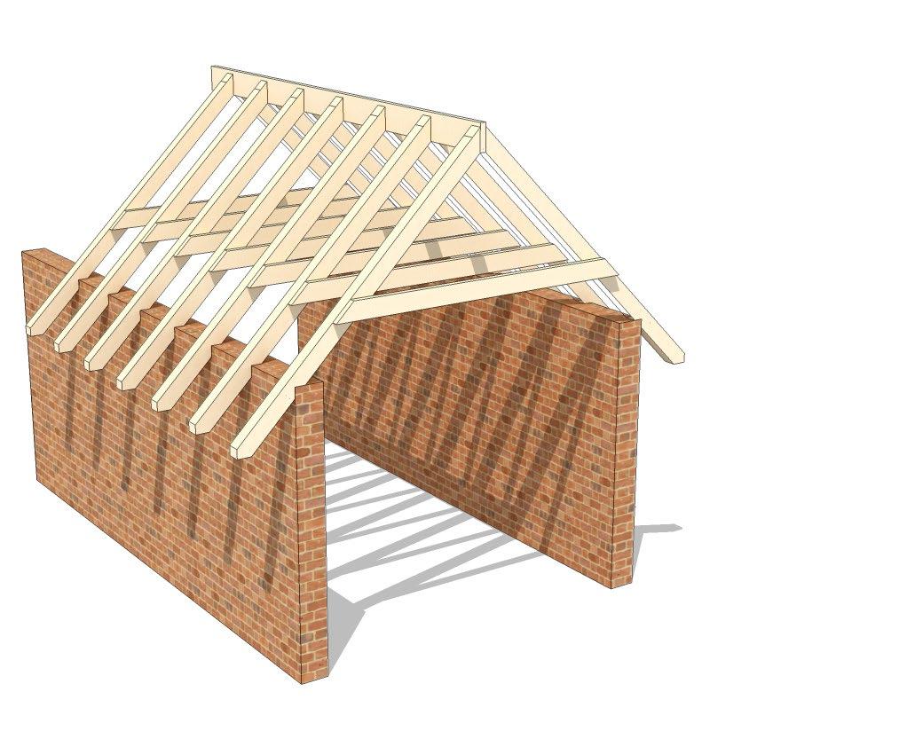
Figure 5.7 - Collar roof and purlin roof
Truss Roof - a truss roof system is a prefabricated triangular frame of timbers tied together. As the trusses are prefabricated, predominantly mechanised, it results in a very accurate finish to the roof system. The trusses are delivered to site ready to be lifted into position. They are fixed to the timber wall plates. The Building Regulations Approved Document Part A provides specific requirements relating to stability of trusses roofs and associated bracing. Some domestic timber trusses can span up to 15m. The disadvantage of the truss roof system is the loss of attic space for storage or additional rooms which tends to be in demand these days. It is not possible to convert a truss roof into a usable loft space that has without major structural works, such as new purlins, floor beams and joists.
A pitched roof is usually covered with a roof tile, some of the most common types covered previously in Section 3 - Materials. Beneath the roof tiles, a secondary weather proof barrier is provided using a sarking membrane, usually in the form of a bituminous felt or sheet, or a proprietary reinforced plastic sheeting. The membrane is placed over the rafters with the tile battens nailed on top. At the eaves, the membrane is dressed into the gutter so that any moisture that has penetrated the tiles can run freely into the gutter.
EAVES
The eaves of a roof can be described as the lowest courses of tiles and the timber that supports them. The eaves of a pitched roof tend to extend around 150-300mm beyond the external face of the wall, to provide protection from rain. In some cases a closed or flush eaves can be designed, which stops the rafters and ceiling joists at the face of the external wall, where a fascia board is then fixed to the ends of the joists and the rafters.
A closed eaves provides soffit boards with ventilation gaps or channels to allow air into the roof space, to be expelled at ridge level.
Figure 5.8 - Eaves example INSULATING THE ROOF
Providing sufficient roof insulation design is key to minimising heat loss through the fabric of the building. The Building Regulations specify a minimum U-value for the insulation of roofs of dwellings to be 0.13W/m2K target notional, with a maximum 0.2W/m2K limiting fabric parameter.
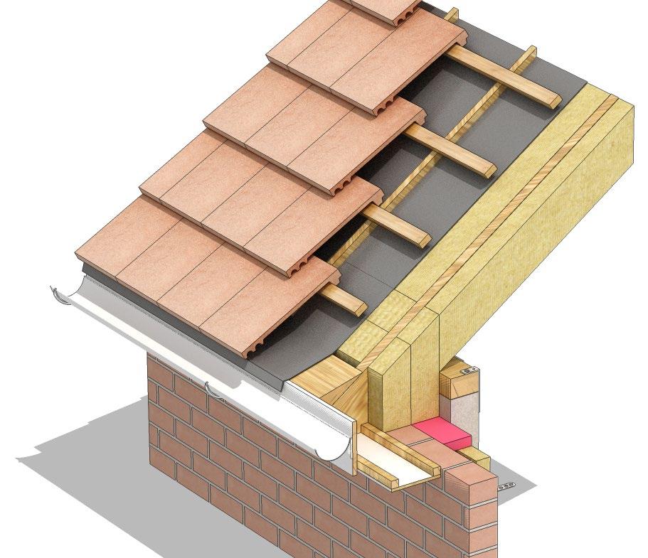
Cold Roof The roof can be insulated in a number of ways. Insulation can be fixed between or across the ceiling joists, an economical option as the area of the ceiling is less than the slopes of the pitched roof. This is defined as a cold roof. Any water carrying service pipes, water storage cisterns in the roof will need to be insulated to prevent damage from freezing, as the roof space itself is a cold unheated space. This type of roof system requires ventilation, in order to prevent a build up of condensation in the roof space.
Warm Roof A warm roof construction is used when the roof space is used for storage or as part of the building itself. The insulation is fixed either between the rafters, or above or under the rafters in varying combinations. The advantage of this system is that the roof space will be warmed by heat rising from the rooms below.
Warm roof and cold roof construction is also seen in flat roofs, discussed later in this chapter.
Figure 5.9 - Cold roof example
Figure 5.10 - Warm roof example
MOISTURE CONTROL
The Building Regulation Approved Document Part C requires that the roof is designed, constructed and insulated in such a manner as to prevent the build up of condensation and growth of mould.
Condensation forms on surfaces within the structure when warm moist air from inside the building moves to the cold side of insulation. If water vapour is allow to penetrate cold areas of the building or structure the air will not be able to hold the moisture and condensation will form on the cold surfaces.
Condensation can be prevented by the use of roof ventilation, which removes the warm moist air. It is also best practice to install a vapour check (vapour barrier) immediately below the insulation, to prevent the flow of warm moist air.
The most effective ventilation method provides ventilation openings at the eaves, with ventilated ridges to allow the air to pass through. Building Regulations Approved Document Part C provides requirements for the design of ventilation in roof spaces to prevent the build up of condensation. It is important to provide a channel or tray over the insulation in order to allow the air to pass through from the eaves.
In a warm roof configuration, ventilation must be provided above the insulation, following the line of the rafters. A 50mm clear gap should be provided between the roofing felt and the top of insulation which leads to the ridge vent. If this is not implemented condensation can occur above the insulation on the roofing felt, and cause problems of rot, poor insulation performance and general damp issues.
However, breathable sarking membranes negate the need for ventilation directly above the insulation layer. They have a low vapour resistance which allows water vapour to escape through the breathable membrane to the outside of the building. Some of the following examples show the specification of such a breathable membrane.
A vapour control layer (vcl) should be installed at ceiling level underneath the insulation - this will help reduce the amount of moisture entering the roof space from the habitable rooms below. The vapour control layer cannot be used as a substitute to roof ventilation, but as an additional defence. It is worth noting that vcl’s can have vulnerable areas of leakage, for example light fittings, joints and loft hatches to mention a few. Seals added to those weak points can help to reduce the amount of vapour that enters the roof space.
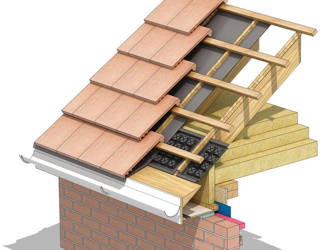
Figure 5.11 - Ventilation through the roof using cross flow ventilator
FLAT ROOF
A roof is considered to be flat when it is of a slope of 1-5o to the horizontal. Although flat roofs are cheaper to build than pitched roofs, they have a shorter life span.
A flat roof usually consists of the following: • Waterproof membrane to prevent water penetrating the structure and interior of the building • Roof deck, providing the base for the waterproof membrane, and in some cases the insulation • Thermal insulation • Load bearing or primary structure, usually constructed in timber in a residential construction.
The construction of the flat roof is similar to that of the timber upper floor. Joists are placed on edge, spaced at 400-600mm centres, supported by external and internal load bearing walls. TRADA and Approved Document Part A give guidance on sizes of joists for flat roofs relating to spans and loading. Strutting is fixed between the joists to provide lateral restraint.
Depending on the roof build up, a roof deck, is then fixed to the joists over firring strips, to provide the fall of the roof. The roof deck material is usually chipboard or plywood. The firring strips allow the roof to have the slope required to enable water run off to the rain water outlets. An alternative to this method sees insulation boards made into shallow wedge sections to provide the fall.
INSULATING A FLAT ROOF
Similar to the pitched roof, a flat roof can be insulated as a cold or a warm deck. The position of the insulation dictates which type it is.
Cold Roof/Deck A cold roof system sees the insulation placed immediately above the ceiling between the joists, with ventilation space above the insulation. The disadvantage of this method is wasteful cutting of insulation to install between the joists, labour required to install the material and increased electrical cables required to prevent overheating, that run within the insulation. It is also difficult to provide suitable ventilation of the void above the insulation to prevent condensation. This roof system is rarely used these days.
Warm Roof/Deck (Sandwich roof) Warm roof systems benefit from the insulation sitting above the deck. This enables the temperature of the structure and the deck to be kept close to the temperature of the inside of the building (hence warm). The insulation is tapered to provide a fall to the roof to enable water to run to the water outlets.
With the warm roof deck, there is less likelihood of condensation forming in the warm roof space, so ventilation is not required. A vapour control layer is still installed to minimise any moisture movement. This system is probably the most common arrangement for residential flat roofs.
The disadvantage of this roof system is that the insulation is directly under the roof covering, so the covering suffers considerable temperature fluctuations. An inverted roof system avoids this issue.
Inverted Roof The inverted roof puts the insulation above the roof covering. The insulation is then protected with a layer of chippings or concrete paving. This system is often seen in more commercial projects.
Both of the warm roof options prevent wasteful cutting of insulation and decrease installation time, therefore labour costs.
PARAPET WALLS
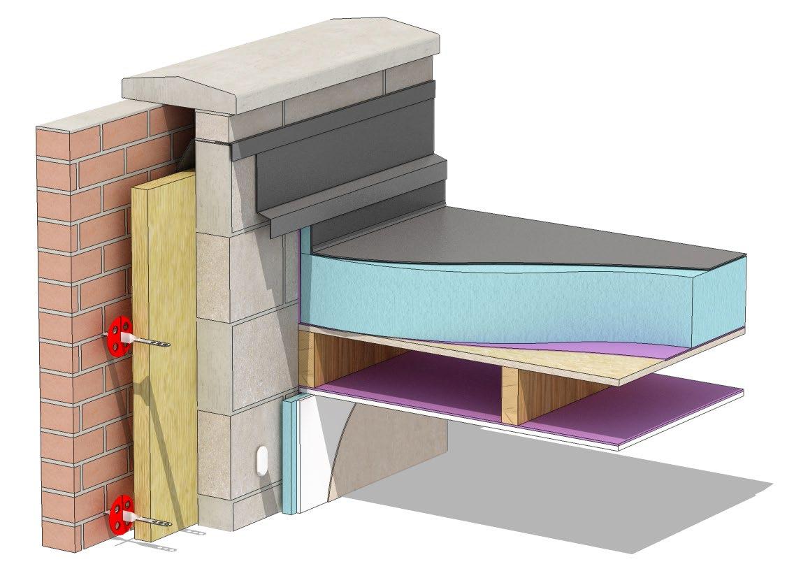
External walls of a building can sometimes be raised above the roof level as a parapet wall. A parapet is exposed on both faces and are more susceptible to damage from driving rain, frost and wind than external walls below eaves level. Building Regulations Approved Document Part A sets guidance to the thickness and height of parapet walls.
It is important to adequately protect the top surface of the parapet wall with a cap or cover that can prevent rain saturating the wall. Natural stone is often used, which project about 50mm either side of the wall, with a drip edge on the underside. Coping stones, either natural or cast, are available in different sections to ensure good run off and protection. Metal flashings are also used as a capping to parapet walls.
The parapet wall has a DPC installed to prevent moisture in the exposed parapet penetrating the roof.
Figure 5.12 - Parapet wall example
