14 minute read
DETAILING PRINCIPLES
DETAILING PRINCIPLES
INTRODUCTION
Advertisement
There is not one book, resource, or website that will ever provide a one size fits all answer to our construction detailing requirements. Every project is different, and with that, the designer is faced with a multitude of choices that need to be assessed and decisions that must be made.
The designer must consider selection of materials and components, meeting client requirements, financial restraints and budgets, aesthetic aspirations amongst many other things. It is crucial that guidance documents are consulted, manufacturer information, regulations and standards in order to present the most effective solution to the problem.
Some key sources of information are described below.
• Building Regulations Approved Documents https://www.gov.uk/government/collections/approveddocuments • British Standards http://shop.bsigroup.com/Browse-by-Sector/Building--Construction/?t=r • Building Research Establishment (BRE) publications http://www.bre.co.uk • Trade Association publications • Manufacturer technical guidance and literature • Building Information Centres • BBA - British Board of Agrement - http://www.bbacerts.co.uk
The details in this book are meant as a guide - a base point for your own development of construction details. They shouldn’t be copied as a quick solution to any construction problem - but be used as a starting point. You should question the detail.
• Is it right for your scheme, how does it integrate with the rest of the design? • What should I change, and why? • What elements need to be implemented from building regulations or guidance documents? • How would this detail work in my particular region of the country?
It is important to develop a critical approach, analyse the details and provide your own solution to each situation. Particular attention must be paid to junctions, due to the complexity of the geometry at these points, heat and moisture flow will not be straight through the fabric but influenced by both two and three dimensional effects. A junction is likely to contain structural elements that will have a higher thermal conductivity than the materials surrounding them. Junctions are also places where different materials meet, which can have differing properties, resulting in possibility of air gaps, movement and so on.
Beyond the guidance documents it is important to develop a key understanding of the detailing principles so that you are able to select strategies and solutions naturally, with a full understanding of the requirements and purpose of each construction detail or element. This next section looks at understanding the performance of the detail and what is required to address common functional requirements of a building.
Water can penetrate a building when there is an opening in the building assembly, there is water at the opening, and there is suitable force to push the water through the opening. This opening can be a crack around a window or door, a gap between a roof tile or a joint between two elements of cladding. In order to stop water penetrating a building we must try to reduce the openings in the building assembly, keep water away from the openings that do occur, and neutralise the forces that can move the water through the assembly.
Reducing gaps and openings in the building assembly is about finding ways to eliminate these openings. Sealants and gaskets are a form of doing this, however a building skin shouldn’t rely on this alone as sealants and gaskets will leak over time. It is better to create an overall strategy that addresses all three elements to be sure of a watertight design.
Strategies to keep water away from the building include methods such as a wash, overhang and overlap amongst others. These will be addressed individually in this chapter.
The forces that can push water through a building assembly are:
• Gravity: water will naturally move downwards • Surface tension: causes water to cling to underside of a surface where it can run through into an opening • Capillary action: water can also move upwards - cracks or holes with smooth sides may act as capillary and by mechanisms of surface tension, draw in water • Momentum: wind-blown rain possesses momentum that can move it through an opening • Pressure differential: water will move from areas of higher pressure to areas of lower pressure
Forces Neutralised by Gravity Wash and overlap Surface tension Overhang and drip Capillary ac9on Capillary break Absorp9on Drain and weep Momentum Labrynth Air pressure differen9als Rainscreen assembly
Figure 2.1 - Forces leading to moisture ingress
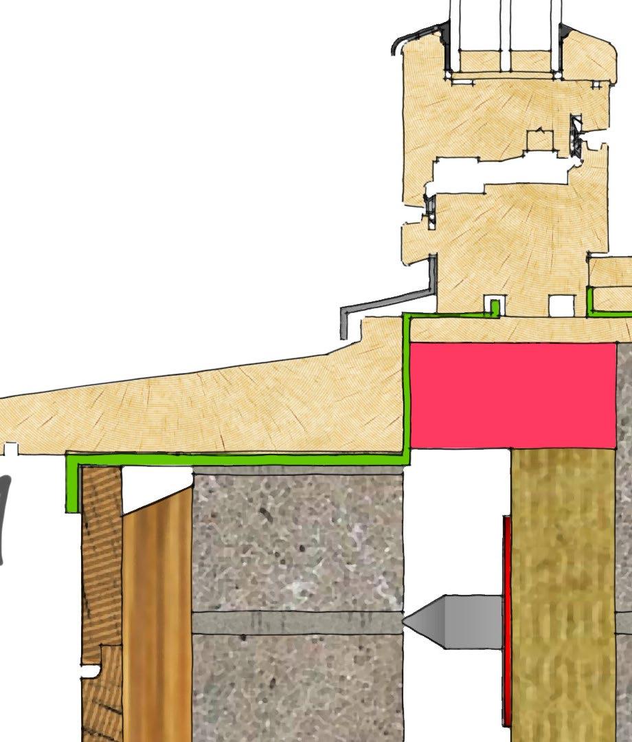
A wash is a slope given to a horizontal surface to drain water away from the building. A wash is used in door or window sills, sloping roof, slopes to drain, ground slopes away from a building. If the material is particularly porous it is important that the slope is steeper to allow for a faster removal of water.
Figure 2.2 - Wash of a parapet coping stone
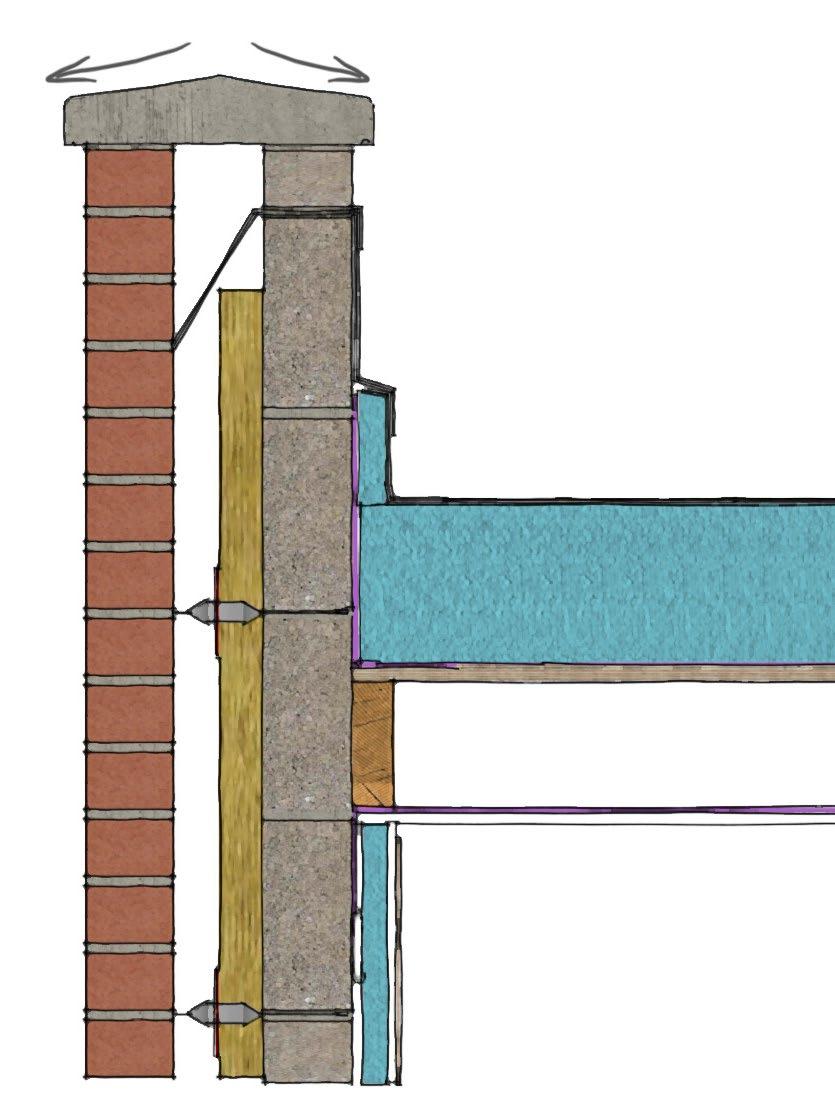
Figure 2.3 - Wash of a flat roof with insulation cut to falls
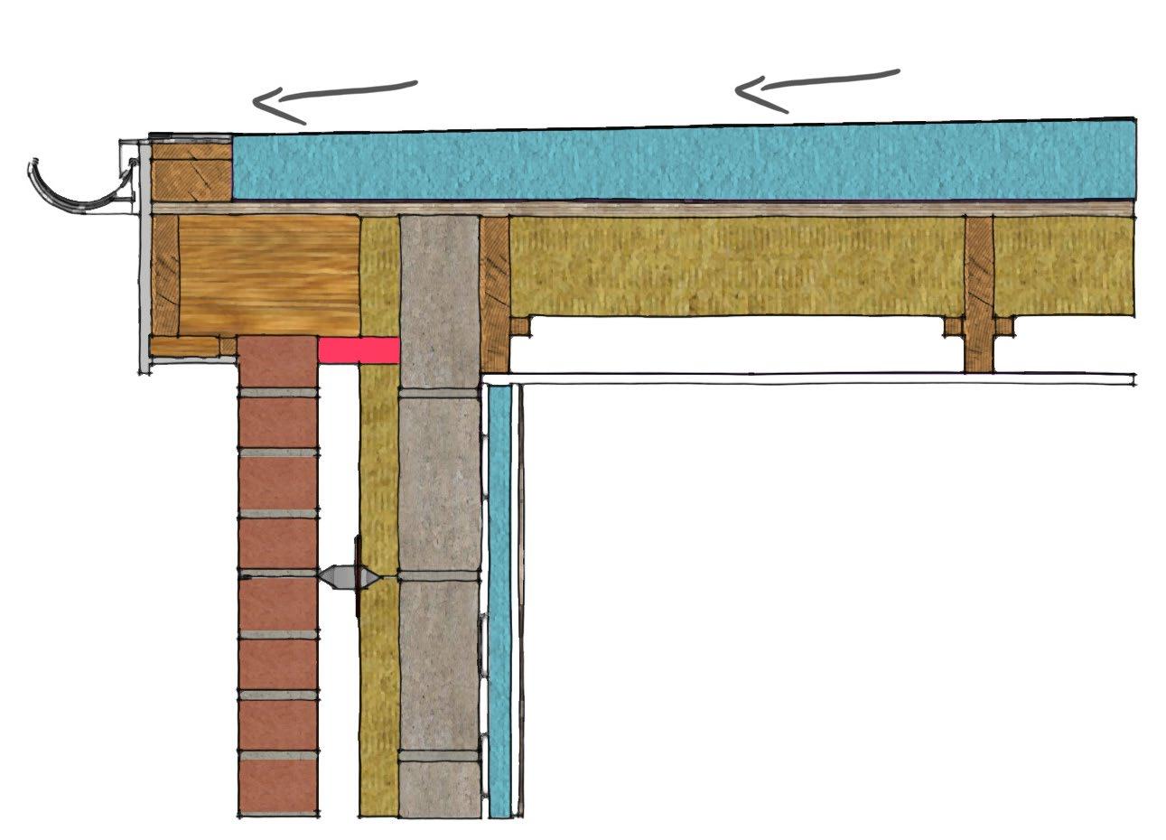
Figure 2.4 - Wash of a window sill
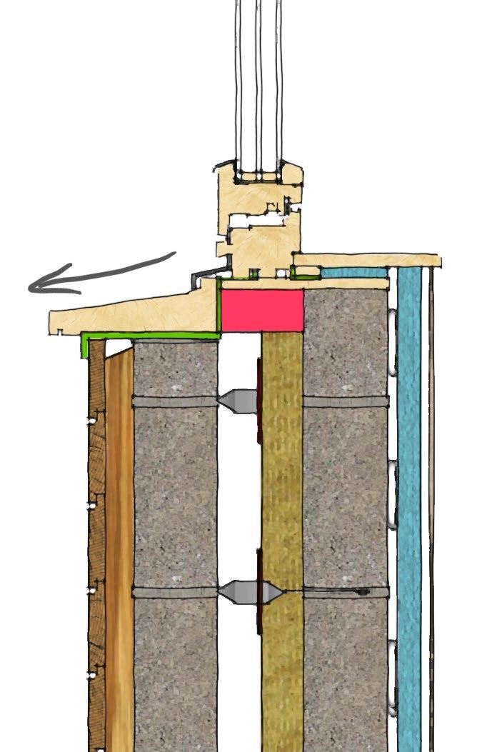
Used on a sloped or vertical plane, an overlap is where a higher element is extended over the lower element with enough distance that water cannot run behind or beneath the element. Gravity pulls the water down the sloped or vertical plan away from the overlap. An obvious example of this would be tiles on a roof. If the material is particularly porous it is important that the slope is steeper to allow for a faster removal of water.
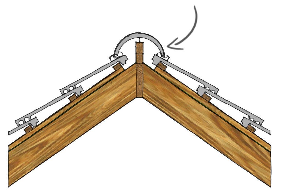
Figure 2.5 - Overlap of ridge tile

Figure 2.6 - Overlap flashing to roof light
Figure 2.7 - Overlap of roof tiles
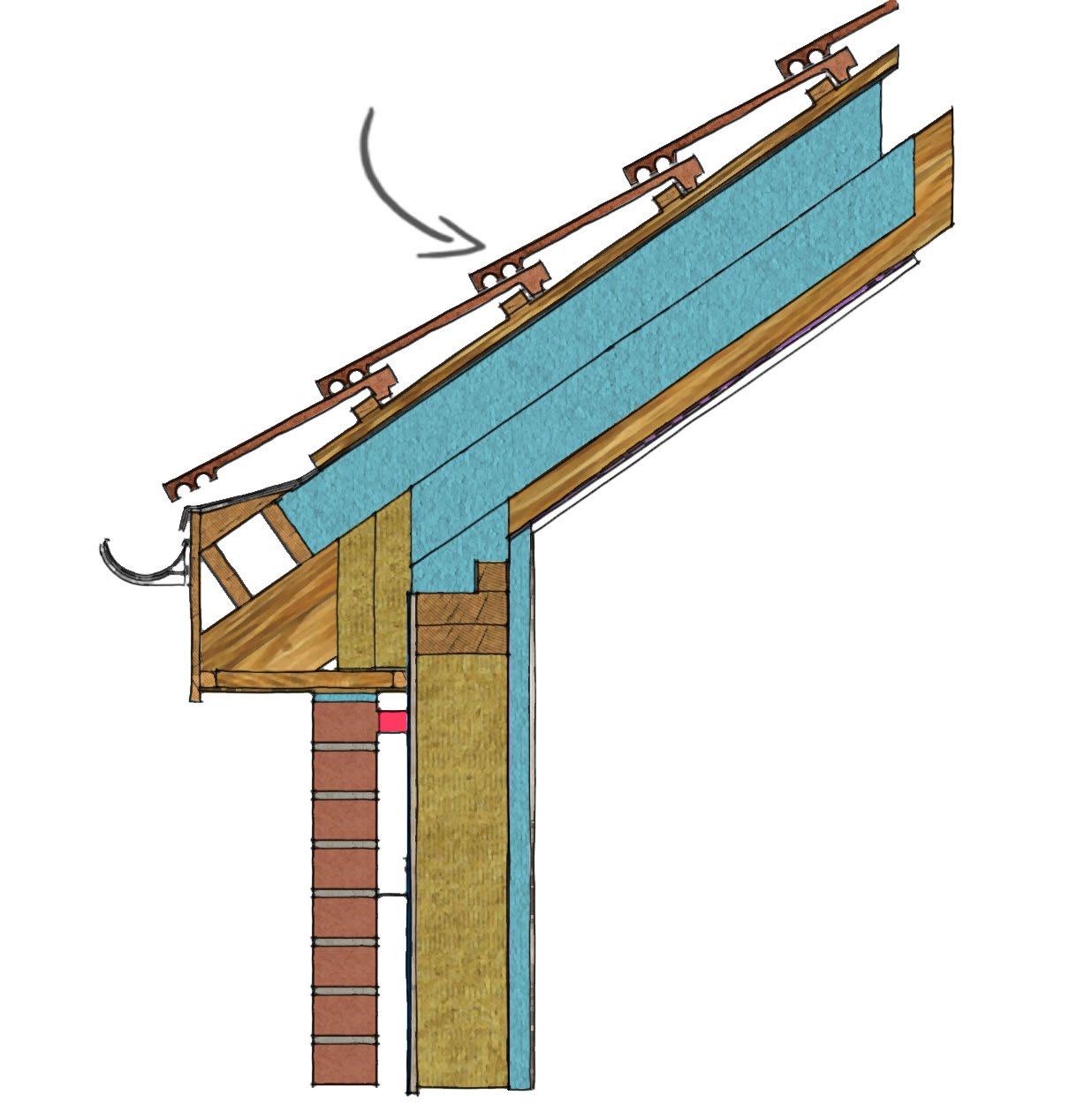
Water running down a wall or element of the building assembly can be diverted from an opening by creating a projection above the opening - this is the overhang. The water is then forced by gravity to drip away from the overhang using a drip, often a groove on the underside of the overhang. An example of the overhang and drip can be seen on window sills, door sills, and coping.
Figure 2.8 - Overhang and drip of roof eaves

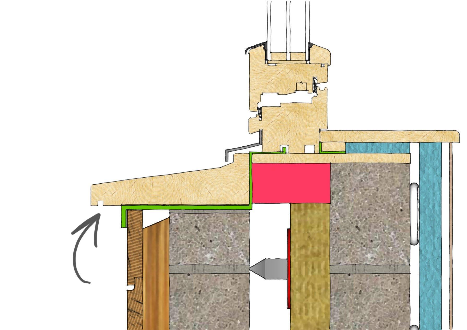
Figure 2.9 - Overhang and drip of window sill

Capillary action is the process in which water is able to pull itself upward or across a narrow crack. The crack has to be narrow for the water to be able to travel. In order to prevent capillary action, a break is provided so the water cannot bridge it.

Figure 2.11 - Capillary break of a window flashing Figure 2.12 - Capillary break in a vertical panel joint
DRAIN AND WEEP
In some constructions we can anticipate that water will penetrate the assembly and in this case we can detail in suitable measures. A drain and weep allows water to be conducted away from a cavity for example, and allowed to drain out of weep holes within the assembly. It can also be a suitable system to control any condensation that has built up in the construction. The drain and weep is used in masonry cavity wall construction.
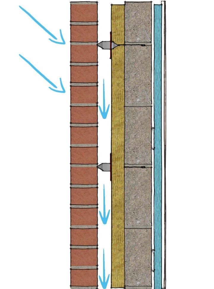
Figure 2.13 - Drain and weep of a cavity wall
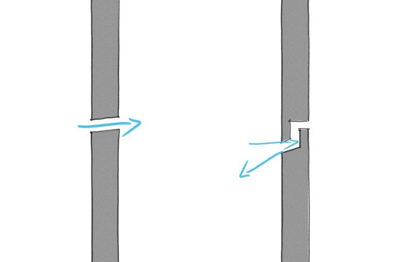
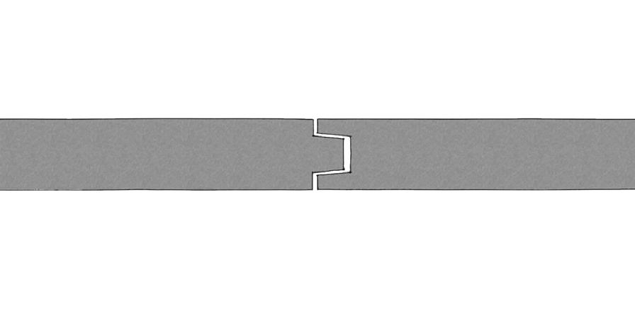
A labyrinth is used in a joint to stop a raindrop passing through the joint. The labyrinth is designed so that there is no straight line through the joint for anything to pass through with its own momentum.
WATER VAPOUR
Figure 2.14 - Labyrinth in both vertical and horzontal joints between panels
Water vapour is always present in the air, however it can cause problems if it condenses on or within the building assembly. Condensation is caused when the moisture laden air comes into contact with a cold surface and the water vapour within the air is deposited as water onto the surface. Windows, solid walls on exposed parts of the house, cold water pipes and thermal bridges are all areas where condensation is most likely to occur. In turn, condensation is less likely to occur on double glazing or a well insulated wall because the internal temperature will be relatively high, above the dew point.
Interstitial condensation occurs when moist air permeates through elements of the building fabric. Typically, there will be a temperature difference across the building assembly, so as warm moist air passes through the structure towards the cooler air the temperature will drop. The dew point may be reached which is when the temperature is cool enough for the water vapour in the warm air to condense on the building fabric. This can cause many problems in the building assembly.
Water vapour is often produced by activities in the house such as bathing, cleaning, drying clothes, cooking. These activities lead to condensation.
General precautions and procedures to avoid condensation include: • the prevention of excess moisture being generated - this is largely down to the occupants. • removal of excess moisture - in the form of suitable ventilation
There are some detailing principles that should be adopted in order to avoid water vapour condensing on or within the building assembly:
High air and fabric temperature will reduce the risk of condensation by keeping the temperature of the structure above dew point. This is best achieved with suitable thermal insulation - seen later in this chapter.
Other principles adopted to avoid water vapour condensing include the use of a vapour control layer and breather membrane.
A vapour barrier or vapour control layer is usually placed on the warm side of the insulation in order to reduce the passage of water vapour and potential problems of interstitial condensation. The VCL is a thin sheet material which reduces the diffusion of water vapour and improves the airtightness of the building fabric which in turn limits uncontrolled ventilation and leakage of warm moist air into the building assembly.
In timber frame, or steel frame construction it is most common for the air and vapour control to be served by one membrane and air and vapour control layer (AVCL).

Figure 2.15 - Vapour control layer Figure 2.16 - Breather membrane
BREATHER MEMBRANE
A breather membrane is a vapour permeable membrane, often positioned on the outside of a construction to protect vulnerable construction elements from rain during construction, and as a secondary protection throughout the life of the building. The breather membrane allows any trapped moist air within the construction to pass through and escape, while stopping any new moisture from penetrating the construction. It is typically seen on the outer face of a timber frame wall.
As we have mentioned in the previous chapter, leaking air can cause a number of problems to not only the structure but our occupants as well. An air leak within a building assembly can result in building performance problems such as: • uncomfortable drafts • wasted heated and cooled air which results in lost energy • interstitial condensation resulting in damage to building fabric or reduced performance • surface condensation resulting in mould growth, damage to finishes • sound leaks • transmission of heat or smoke in a fire from one part of the building to another
An air leak is an uncontrolled passage of air through an exterior wall of a building. Studies have shown that air leakage can contribute up to a third of total heat loss in a dwelling. For air leakage to occur there must be a pressure difference between the two points and a continuous flow path or opening connecting those two points.
AIR BARRIER SYSTEM
In order to reduce air leakage it is important to create an air barrier system that seals all openings at one plane in the building envelope. Great care needs to be taken when detailing junctions to ensure the air barrier remains constant.
In masonry construction the air barrier is often formed as part of the internal leaf of the cavity wall. If the inner leaf is well built with a coat of wet finish plaster properly applied with correct detailing, air tightness will be achieved. Dry-lining can also deliver air tightness, if detailed with appropriate sealing and taping, but often use of an airtight membrane is advised for improved performance in both cases.
In timber frame or steel frame construction the vapour control layer often serves as the airtightness barrier. The airtight layer is usually at or close to the inside of the building insulation envelope which also serves to prevent warm moist air from entering the building assembly.
Sealants, gaskets and weather strips are also used to ensure air tightness. Door and window openings utilise weather strips or gaskets to reduce possible air flow.
The excessive conduction of heat through a building can result in wasted energy, high heating and cooling costs, condensation leading to mould and general discomfort for the building occupants. Controlling this heat flow is crucial and this can be achieved by engaging a few detailing principles.
A thermal bridge, sometimes referred to as a cold bridge, is a weakness or discontinuity in the thermal envelope of a building. Most often seen at junctions, a thermal bridge occurs when the insulation is interrupted by a material more conductive. At these junctions heat can be lost as it is able to pass more easily through the building assembly. Thermal bridging can contribute quite significantly to overall heat losses in an otherwise well insulated dwelling. A thermal bridge can also result in condensation build up and mould growth which in turn has an effect on the building occupants. This occurs where the element that passes through the insulation layer creates a lower surface temperature and those locations, resulting in both surface and interstitial condensation.
When developing details, it is important to ensure the insulation layer remains consistent and unbroken to minimise thermal bridging. Insulation should be tightly fitted against and between construction elements to eliminate gaps and prevent slump or movement that could degrade performance.
THERMAL BREAKS AND ELIMINATING THERMAL BRIDGES
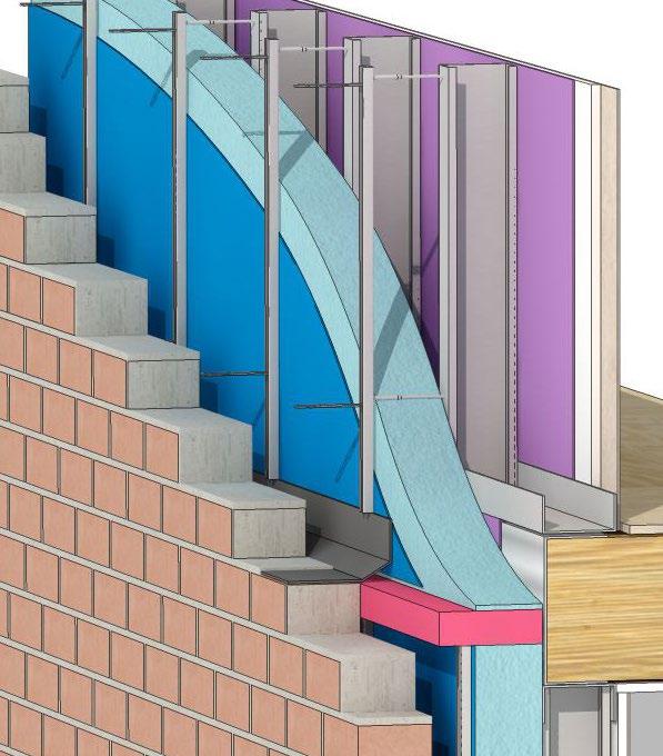
A thermal break is an insulation strip that is inserted into the building assembly where there is a risk of increased heat conduction. An example of this could be in a timber frame wall. The timber stud work will conduct heat more rapidly than the insulation between the studs. A layer of insulation is added to the inside or outside of the frame to improve the overall thermal resistance of the wall. The stud work of a timber frame wall can make up 15% of the wall, so it is worth countering this with the extra insulation. Another example of a practical use of thermal break would be in a steel frame wall, where metal conducts heat at a much higher rate.
The key design aim for any junction is to ensure that there are no single elements or combination of elements that will conduct heat more rapidly through the construction. A continuous layer of thermal insulation should be designed throughout the building envelope. Heat loss can be reduced by ensuring any junctions allow the insulation within different elements to abut and/or overlap.
To avoid condensation risk there are two methods that can be considered. The first is a vapour permeable construction where the vapour permeability on materials from the warm side to the cold side of construction are increased. This allows water vapour to pass through the construction to reach a ventilated zone where it can be dispersed. The second is to install a vapour control layer on the warm side of construction to prevent the water vapour from penetrating areas of the building assembly that can cause problems. This option should always be used if there is not suitable ventilation to disperse the water vapour.
It is also worth noting that the use of two different types of insulation can cause condensation. If a rigid insulation is used with a fibrous insulation, the rigid insulation must be positioned on the warm side. If positioned the other way around, the water vapour could pass through the fibrous insulation and become trapped when it meets the rigid insulation creating a potential build up of condensation.
It is possible to read more about the risk of surface condensation in the document BRE IP 1/06 “Assessing the effects of thermal bridging at junctions and around openings” and BS 5250:2011.
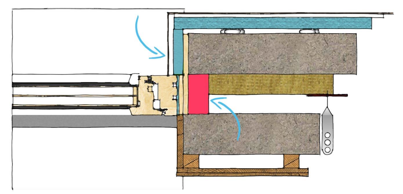
Figure 2.18- Insulated plasterboard reveal and PU/PIR insulated cavity closer to window jamb
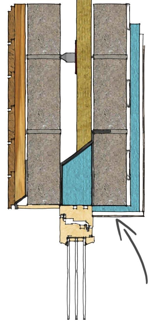
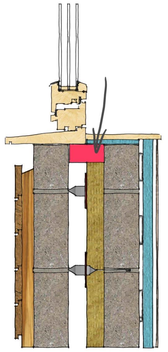
Figure 2.19- Cavity closer with PU/PIR insulation core, insulation under internal window sill
Figure 2.20- Increased eaves insulation

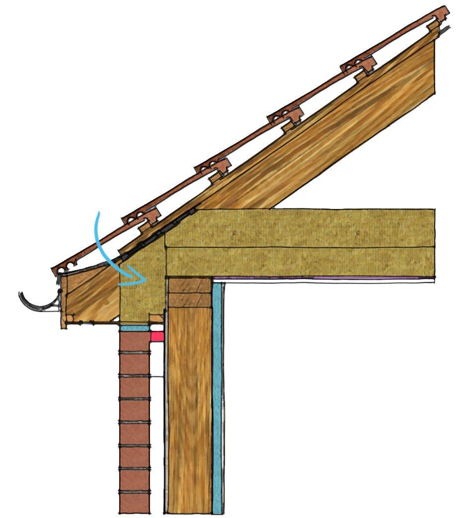


Figure 2.22- Additional insulation on inside face of a timber frame and steel frame construction
Figure 2.21- Perimeter insulation to concrete slab and lightweight blockwork to innerleaf


