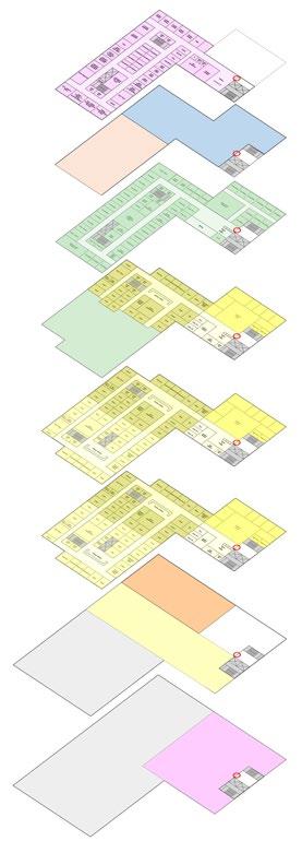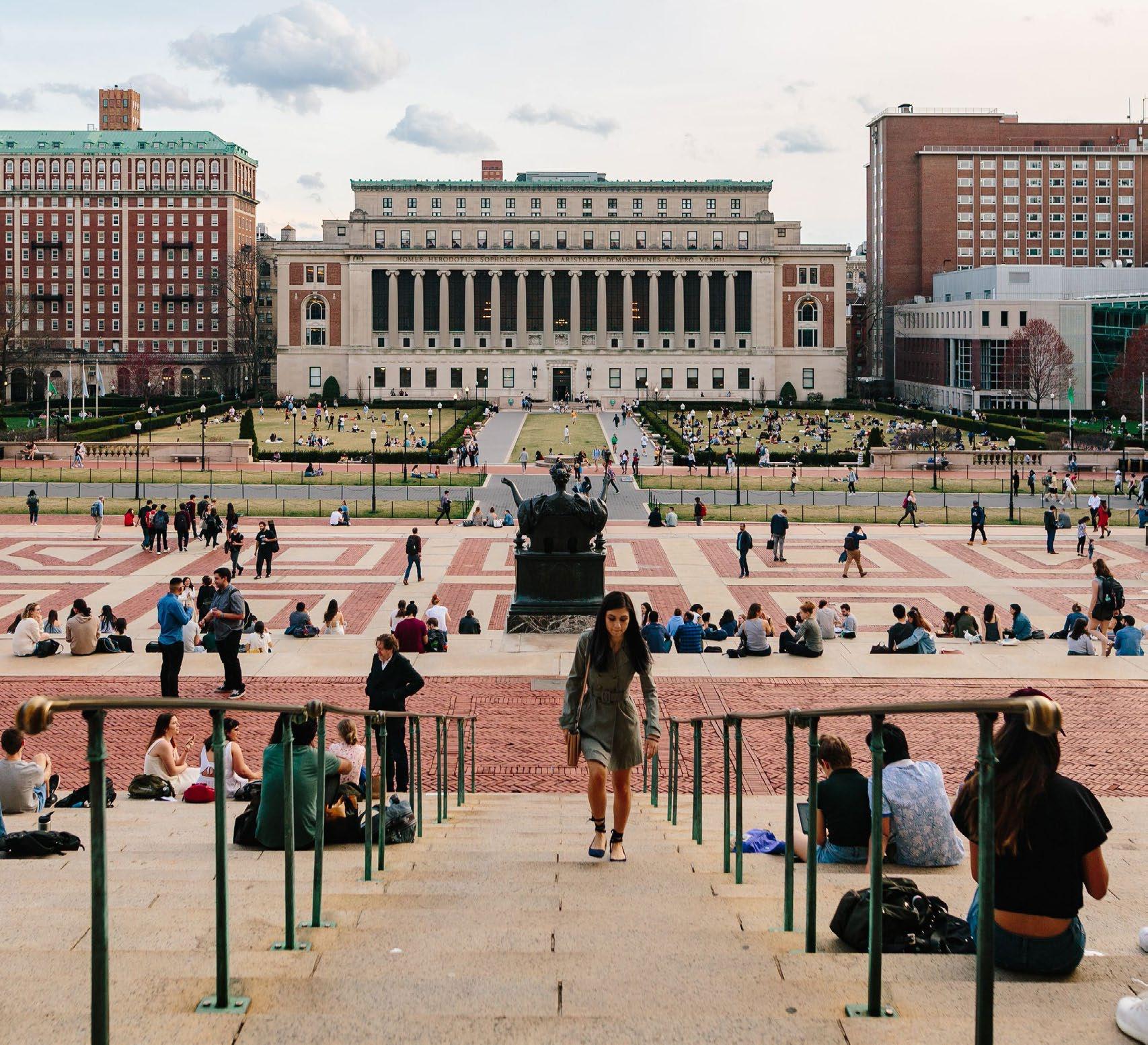


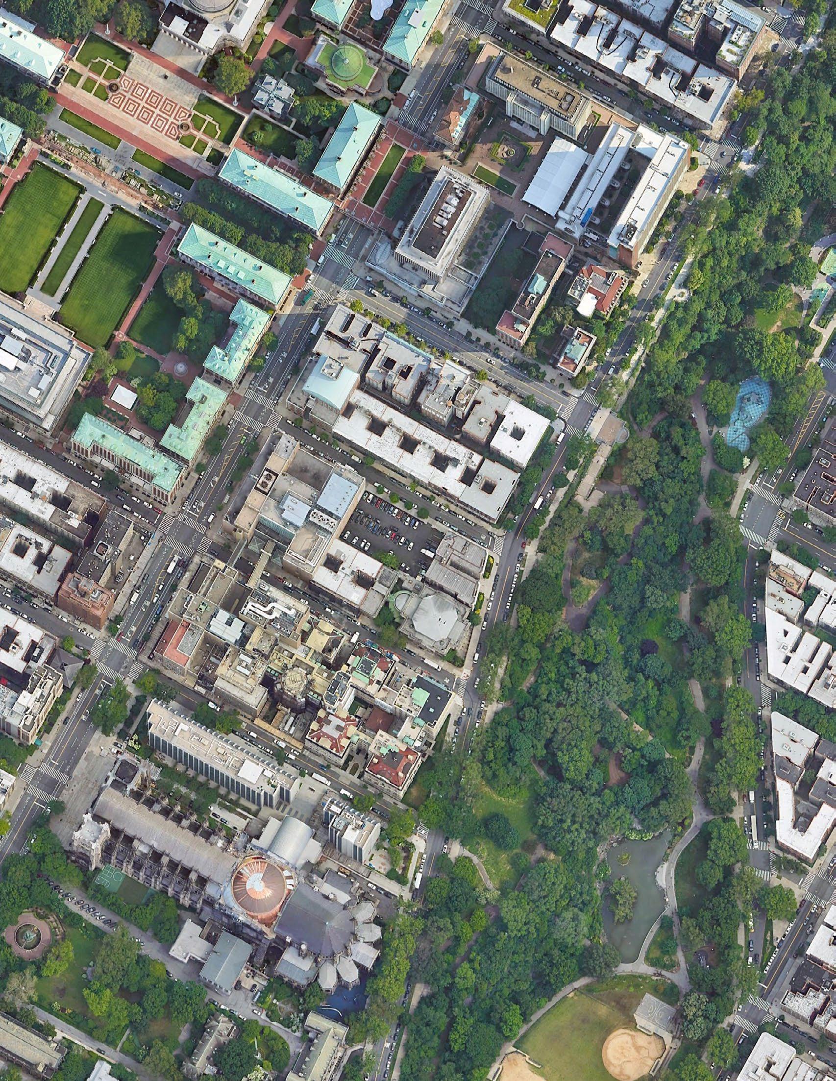
“Site 1,” located between Amsterdam Avenue and Morningside Drive, consists of an existing parking lot on 115th Street and a Clinic Building on 114th Street. These two parcels constitute a substantial development site close to Columbia’s historic campus core. The site is one of the most significant opportunities for new construction remaining near the center of the campus and is well-positioned for programs that serve a campus-wide constituency. To the west, 115th Street terminates in an architecturally significant gate (currently closed) between Wallach and Hartley Halls and its re-opening could offer a strengthened pedestrian campus connection from this site to the central core.
This study examines the opportunities afforded by “as-ofright” zoning to accommodate a new building on this site for a mix of several different program uses. There are a number of site specific opportunities and challenges, including existing easements and development agreements with the adjacent hospital, potential air rights transfer, and the ability to use an alternate “as-of right” zoning rules for tower massing. In addition, the site was studied for the possibility of rezoning to “Contextual Zoning,” which would add some additional constraints to height and setback requirements.
The key programs identified by the University as potential candidates for Site 1 were undergraduate residences, a new Health Services Center, an additional dining facility and a satellite recreation facility. In addition, a space titled “Commons” has been included as a campus public space intended as flexible space for gathering, informal study, ancillary dining and to offer connections between the major public programs of the building. The four core programs envisioned for the building all currently experience excess demand and are undersized for optimal performance. In the case of Health Services, their programs are scattered in six locations across campus. Benchmarking research also indicates that Columbia’s existing provisions for Dining, Recreation and Health Services are undersized relative to peer institutions.
The initial selection of these programs recognized that there are beneficial relationships and alignments in their missions, much of which revolves around promoting wellness and the quality of student life and learning. Shared spaces for exercise/meditation, kitchen demonstration, nutrition and health-related education, and informal gathering and learning bridge between the four program areas and can contribute to a unified building identity and character.
The proposed programs for housing and dining used in this study were developed through interviews with Student Residential Life staff, review and tours of existing facilities and review/benchmarking of recent residential projects at peer institutions in urban settings. The program for Health Services and Recreation were derived from a pre-existing Program Studies (Columbia Health Facility Master Plan 2020 and the Dodge Gym Transformation Program 2019) supplemented by departmental interviews.
The optimal space requirements for all these programs will exceed the available development capacity of the site. Therefore, this study initially generated a number of different options of varied size and combination of uses to be located in the proposed project. With the review and input of the University, these options were refined into five basic combinations which were tested against the zoning requirements of the site. Three variants were also developed for the Contextual Zoning Option which has a reduced floor area.
The program options for the proposed building are:
• 300-Bed Student Residence, Dining, Health Services Option 3 & Commons
• 300-Bed Student Residence, Dining, Health Services Option 1, Recreation & Commons
• 400-Bed Student Residence, Dining, Health Services Option 2 and Commons
• 500-Bed Student Residence, Dining, Rec. & Commons
• 600-Bed Student Residence, Dining & Commons
In addition, as part of a 2002 development agreement with the of this development agreement, any proposed development on and placed on its special order calendar as it will have minimal Additionally, under city zoning regulations, the University can apartment building (44 Morningside Drive) with available air rights which has been considered in this analysis.
The combined site offers the capacity to build 189,091 gsf as-of-right, with a possibility to increase this to 217,570 gsf with the transfer of air rights from the Columbia-owned 44 Morningside Drive. Potential air-rights from the Chapel of Notre Dame have not been pursued in the study. (Note that the Chapel is a NYC landmark and therefore transfer would make the developments subject to Landmarks Approval).
This projected area total is derived from the sum of allowable zoning area, deductions for a previous air rights transfer to the hospital, additional allowances for a below-grade floor and non-occupied mechanical/service spaces (neither of which are in calculated zoning area) and any potential air rights transfer.
Spatial restrictions under current zoning regulations are described in greater detail in the body of the study, but are summarized as follows:
• Maximum lot coverage of 65% (excepting portions of a ground floor below 23’ in height)
• A 60-foot combined rear yard for each parcel or two (2) rear yard equivalents
• Minimum setback of 20’ above a maximum 85’ base.
• Additional setbacks above 85’ based on a sky-exposure plane of 2.7:1
• A 30-foot easement on the western boundary, approximately 60’-70’ (Manhattan Datum 198.21) above the street (note that this is not a city requirement, but part of the existing agreement with the hospital)
The as-of-right application of these requirements results in a scheme comprising two building forms, one fronting 114th and one on 115th Street, connected by a common ground floor that runs though block. Each building would require its own egress stairs and elevator core. The need to reduce the building footprint to meet a sky exposure plane means that the higher the building, the floorplate continues to reduce, ultimately creating a practical limit to the building height.
Zoning Regulations allow for an alternative “Tower” massing. This approach:
• Limits Tower lot coverage to 40% (however full lot coverage is still allowed for one floor at ground level)
• Rear yard or 30-foot rear yard equivalents which can be located at each street line
• No setback requirement and tower can penetrate the sky exposure plane
The use of the Tower option allows for a single floor plate, which would not require duplication of egress stairs and elevators. Also, because the site already has 30-foot easement with the hospital to the west, which applies to either zoning scenario, the 40% lot coverage requirement does not generate as substantial a penalty to floorplate size. Combined with less duplication of vertical circulation core, this generates a more efficient overall floor. Because there is no sky exposure plane requirement, these floors do not need to reduce in size as the building height increases.
Contextual Zoning (R-8A and R-9A) has been proposed by a community group (Morningside Heights Community Coalition) for a 35-block area that includes this site. The proposed rezoning has not entered into the required environmental reviews. If Contextual Zoning were adopted for the site there would be no change to the maximum developable area. However, because of a maximum height limit, the site could not fully utilize additional air rights from adjacent properties. Contextual Zoning would require:
• Maximum lot coverage of 70% (excepting full lot coverage is allowed for one floor at ground level)
• A 60’ combined rear yard & street wall requirement
• A setback of 15 feet above a 95’ base.
• A maximum building height of 125’
• A 30’ easement on the western boundary with the Hospital, approximately 60’-70’ above the street, would still apply
Contextual Zoning precludes the option of a tower massing. The “two street bar” arrangement would be similar to that allowed under existing R-8 zoning, but the floorplates could be slightly larger. This is beneficial for programs like Health Services, however increased depth would not be an advantage for student housing floor layouts which can efficiently utilize a narrower floorplate. Most critically, the maximum height of 125’ would likely preclude the full use of available air rights.
The total amount that could be utilized will depend on the floor to floor height required by the selected program types. Housing would typically utilize a lower floor-to-floor height than health services. This study analyzed three of the program options under a contextual zoning development option.
There are viable as-of-right building development scenarios for each of the program combinations explored in this study. The five (5) program options were formulated with the intent of providing a range of space allocations, including scenarios that represented a minimum and maximum conditions for Residential Life and Health Services while still preserving a viable mix of the programs.
There are modest variations in net/gross area and operational efficiencies with certain program combinations, however the differences are not great enough to eliminate any of the program scenarios as viable options. For certain program combinations, largely those involving the larger Health Services component, the Tower Massing scheme offers a significant advantage in planning, area and operational efficiency.
All the proposed scenarios require further refinement as part of a design process, including exploration of entry location(s), further definition of the building’s lower levels for high traffic, public spaces, additional sectional/stair connections between floors, outdoor spaces at the street and rooftops, and the refinement of the boundary between public common and secure spaces. The final selected combination of program elements and space allocations will provide greater clarity for this development.
MORNINGSIDE CAMPUS
Hartley Wallach Gate
AMSTERDAM AVE
114THST
115THST
116THST
MORNINGSIDE DR
113THST
MORNINGSIDE PARK
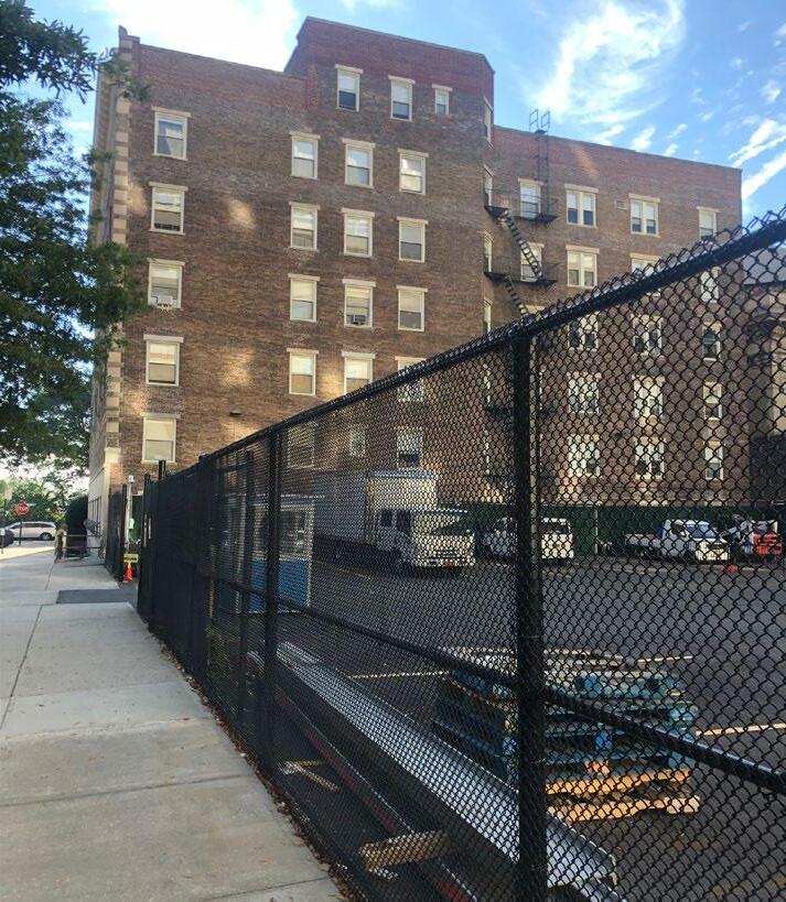
The development site is a through-block L-shaped lot midway between Amsterdam Avenue and Morningside Drive with frontages along 114th Street and 115th Street. The northern portion of the site is an open-air parking lot used by Columbia University Operations and Public Safety Vehicles. The southern portion of the site is occupied by the six-story Clinic Building, constructed in 1926 as an apartment building and currently leased by Columbia University to Mount Sinai Morningside Hospital for use as an outpatient mental health facility.
Adjacent to the site north of 115th Street are six-story pre-war Columbia apartment buildings occupied by Law School Students and a classroom building (Warren) on Amsterdam. Directly to the east of the north lot is Cathedral Court, a six-story faculty apartment building owned by Columbia University which faces Morningside Drive. To the east of the south lot is the three-story Rectory building of the Notre Dame Chapel located on 114th Street and Morningside Drive. The Rectory and Chapel are designated New York City Landmarks. Further to the east of Cathedral Court and the Notre Dame Chapel is Morningside Park with uninterrupted views of Harlem.
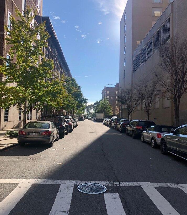
On the west side of the site are buildings associated with Mount Sinai Morningside Hospital, which have a strong presence along Amsterdam Avenue and contribute to a separation between the site and the main campus. The hospital has a loading dock along 115th Street, but the overall character of the street is less institutional than that of 114th Street. Reinforcing connections across Amsterdam Avenue between the historic campus and the site will be one of the main challenges of any future development.
One opportunity for strengthening the connection to the main campus is the opening of the Hartley Wallach Gate on 115th Street and Amsterdam Avenue, which was raised as a possibility in our discussion with user groups at the University. With University-owned housing for students and faculty on both sides of 115th Street adjacent to the site, we envision this as a potential gateway for the new development and its primary orientation towards the Morningside campus.
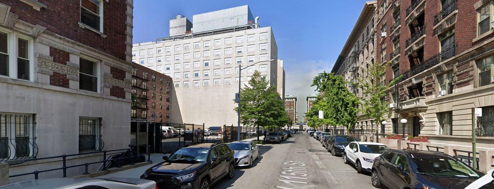

 Looking east at 44 Morningside Drive
Looking west at Mt. Sinai Morningside Hospital
Looking east on 115th Street from Amsterdam Avenue
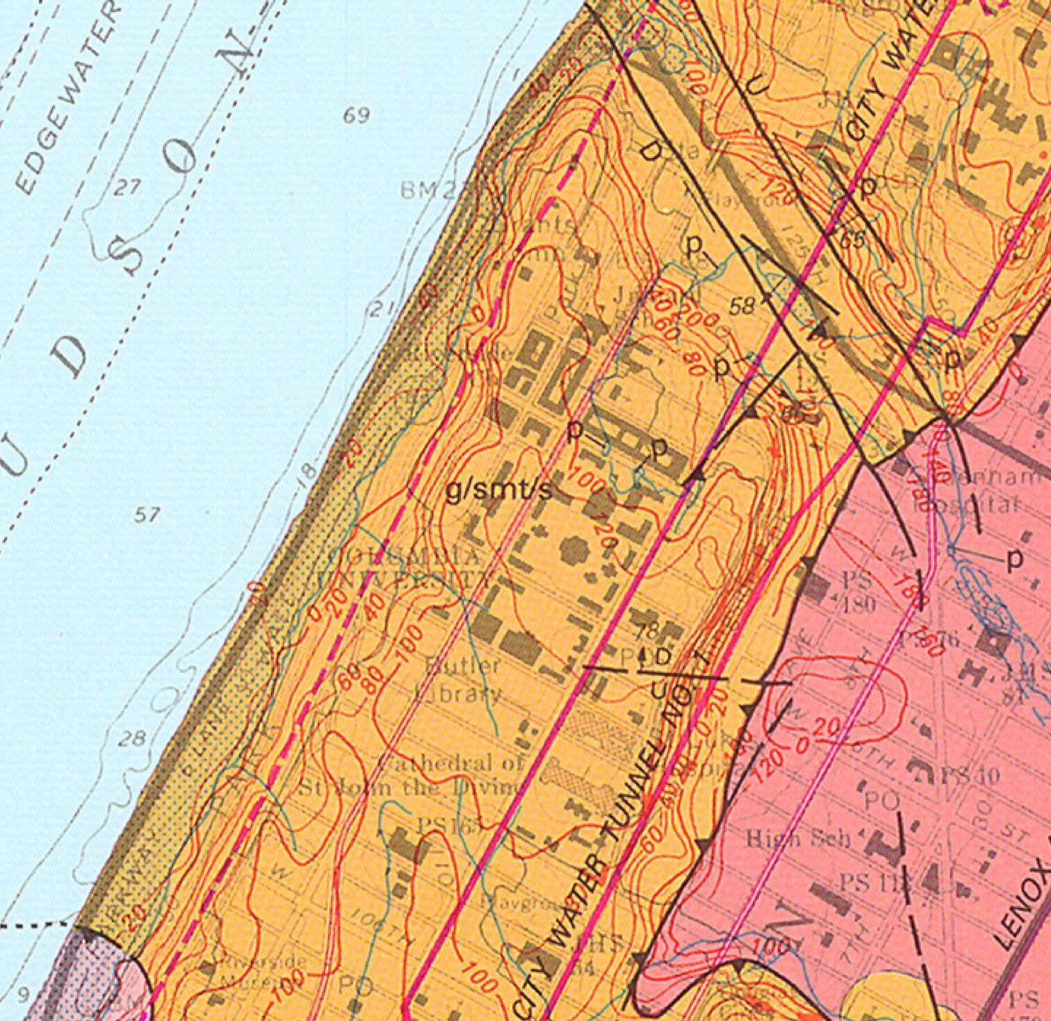
In order to better understand the feasibility of below grade scope for this site, we enlisted the services of Langan Engineering to perform a geotechnical report in October of 2021. They performed three soil borings on the north lot as a preliminary analysis of the subsurface conditions, understanding that a more complete geotechnical report would need to be performed at a later date to support a future design. However, the borings consistently show bedrock at an elevation of about 10 feet below grade, which is not surprising given the location of the site at the eastern edge of Morningside Heights. Because of the proximity of
As a complement to the subsurface investigations, the team also considered opportunities for connecting with existing campus steam and chilled water infrastructure. Although most of the existing infrastructure is on the main campus to the west of Amsterdam Avenue, in our meetings with Columbia commissioning it was confirmed that there are currently hot and chilled water lines servicing east campus buildings north of 116th Street.
However, the work required to connect south to Site 1 is significant and most likely not viable because of the costs and







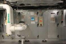


Architecturally, the approach includes envelope target R values and glazing percentages. From a systems perspective, options include ground and air sourced heat pumps, along with various heat recovery systems to reduce load and to introduce alternative energy sources. Regardless of the system selection, the approach will be dedicated and internal. Connecting to the existing campus infrastructure is challenging from a cost and logistics perspective, but more importantly, would not be in alignment with the fossil fuel free mandates under Plan 2030.
The building systems report in its entirety is included in the
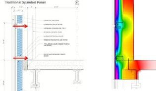
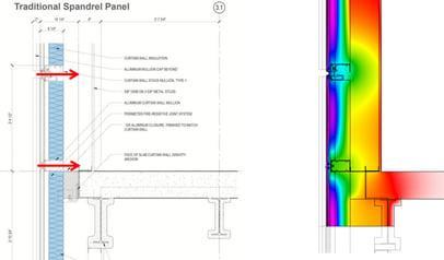
mitigation is an important part of envelope design High risk locations of thermal bridges are (1) boxes/overhangs (2) Corners/junctions (3) Windows Thermal bridge mitigation will be a part of 2023 NYS be adopted by NYC.


High performance buildings have a strong focus on reduced infiltration , tightly sealed, continuous controlled moisture movement. We recommend working with architect to encourage these types improve overall performance of the building’s enclosure.
 Typical thermal bridging through glazed assemblies.


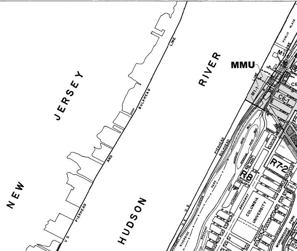
The site is located in an R8 residential district. The proposed development is classified as a community facility use. A maximum Floor Area Ratio (FAR) of 6.5 applies to community facility buildings in R8 residential districts. The maximum FAR must be calculated based on the zoning lot, considering existing conditions and prior transfers of development rights.
Community facility buildings in R8 districts may use the standard height and setback regulations or tower regulations. The key bulk rules are summarized below:
Height and Setback (24-522)
• Lot coverage: 65% (except ground floor)
• Maximum base height: 85’ or 9 stories, whichever is less
• Minimum setback: 20’ (narrow street)
• Sky Exposure Plane: 2.7:1 (narrow street)
Tower (24-54)
• Maximum tower lot coverage: 40%
• Tower portion may penetrate the sky exposure plane
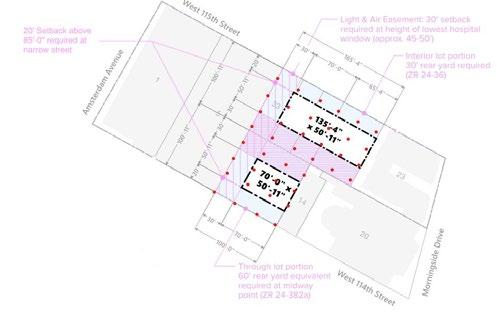
A 30’ rear yard is required for any interior lot portions of the zoning lot. A rear yard equivalent is required for through lot portions of the zoning lot. There are three (3) options per 24-382:
• A 60’ deep rear yard equivalent located at the midway point of the through lot portion
• Two 30’ deep rear yard equivalents extending along the full length of each street line
• Two 30’ deep rear yard equivalents extending along the full length of each side lot line
For scenarios involving a full-block zoning lot, no rear yard or rear yard equivalents are required (23-53).
There is a maximum lot coverage of 65% for interior or through lot portions of a zoning lot (40% for tower) though portions of the building below a height of 23’ can be excluded from lot coverage calculations.
The site plan diagrams on the following page demonstrate how these zoning rules may be applied to two different development scenarios.
Intro page from Zoning Summary Report 1.18.2022 produced by Envelope Zoning
The site plan images below demonstrate how these rules may development scenarios:

Spatial restrictions under current zoning regulations are described in greater detail in the body of the study, but are summarized as follows:
• Maximum lot coverage of 65% (excepting portions of a ground floor below 23’ in height)
• A 60’ combined rear yard for each parcel or two (2) rear yard equivalents
60-70’ above street).
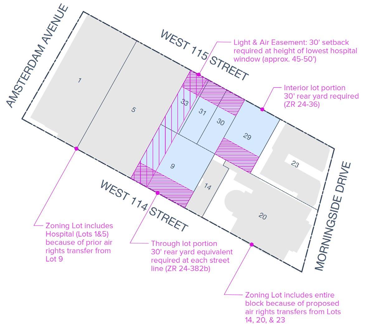
Depending on the scenario, the zoning lot may include existing bulk regulations. The Zoning Resolution includes provisions fo “prevent the creation of additional non-compliances or increas non-compliances” (51-00).
• Minimum setback of 20’ above a maximum 85’ base.
• Additional setbacks above 85’ based on a sky-exposure plane of 2.7:1.
• A 30-foot easement on the western boundary, approximately 60’-70’ above the street (note that this is not a city requirement, but part of an existing agreement with the hospital)
The as-of-right application of these requirements results in a scheme of two building forms, one fronting 114th Street and one on 115th Street, connected by a common ground floor that runs though block. Each building would require its own egress stairs and elevator core. The need to reduce the building footprint to meet a sky exposure plane means that the higher the building, the floorplate continues to reduce, ultimately creating a practical limit to the building height.

Zoning Regulations allow for an alternative “Tower” massing. In this approach:
lot may include existing buildings that may not comply with the includes provisions for non-complying buildings that aim to compliances or increases in the degree of existing
• Tower lot coverage is limited to 40% (however full lot coverage is still allowed for one floor at ground level)
• Rear yard or 30’ rear yard equivalents can be located at each street line
• No setback requirement and tower can penetrate the sky exposure plane
• 30’ easement at hospital is still required
The use of the Tower option allows for a single floor plate, which would not require duplication of egress stairs and elevators. Also, because the site already has 30-foot easement with the hospital to the west, which applies to either zoning scenario, the 40% lot coverage requirement does not generate as substantial a penalty to floorplate size. Combined with less duplication of vertical circulation core, this generates a more efficient overall floorplate. Because there is no sky exposure plane requirement, these floors do not need to reduce in size as the building height increases.
There are certain limitations regarding where the Tower option can be employed when located near a park greater than one acre in size. The use of a Tower option was raised with the Department of City Planning who confirmed it was applicable to this site.
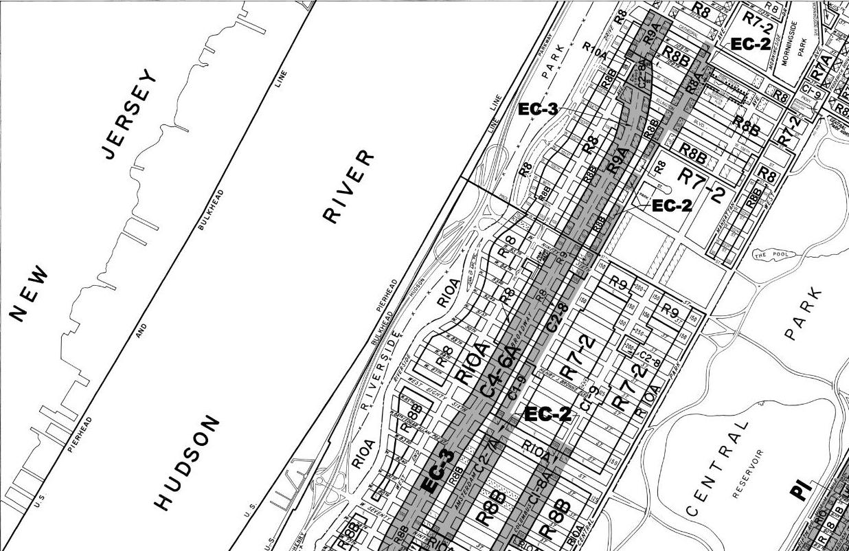
A community group (“Morningside Heights Community Coalition”) is leading a planning proposal that would seek to rezone a 35-block portion of Morningside Heights, including the subject site. The proposal generally seeks to introduce contextual zoning to this area, and would rezone the subject block from R8 to R8A and R9A.
The proposal is preliminary and has not yet entered the City Environmental Quality Review (CEQR) process or Uniform Land Use Review Procedure (ULURP). The group released a report (“Morningside Heights Planning Study) in May 2021 summarizing efforts to date since 2016. At this time, they indicated that they did not currently have funding to proceed with the next steps in the process - hiring consultants to complete an Environmental Assessment Statement.
The group preparing this proposal has received support and resources from local elected officials including Mark Levine, Gale Brewer, and staff from the City Council land use division. It is unclear how the political reshuffling of the 2021 elections may affect the future viability of this project. The proposal may also be revised if/when it moves through the formal land use approval process.
The development site is proposed to be rezoned to R8A. The maximum 6.5 FAR for community facility use would remain the same, but R8A requires buildings to use the Quality Housing bulk regulations, including a maximum 85’ base height and 120’ building height (increased to 95’/125’ if a >13’ ‘qualifying ground floor’ is provided). Quality Housing buildings on through lots are also required to provide a rear yard equivalent at the midpoint; therefore a single building scheme centered on the development site is not as-of-right and would require a discretionary approval.
Portions of the block within 100’ of Amsterdam Avenue (the Hospital) or Morningside Drive (44 Morningside / Notre Dame) are proposed to be rezoned from R8 to R9A, which allows a higher 7.5 FAR. The Zoning Resolution includes provisions for zoning lots that are divided by zoning district boundaries, including the ‘blended’ distribution of FAR based on the lot area in each district. This may allow for a reverse transfer of development rights from the hospital, or additional Morningside air rights, back to the development site, However, the feasibility of using this development rights transfer will likely be constrained by the height limit of the proposed R8A district.
The table below summarizes the key bulk rules that would apply to the development site under the current and potential zoning district:

ZONING + MASSING
Within this framework of the existing as-of-right zoning, Columbia University has commissioned a series of studies to better understand the development potential for Site 1. Our efforts are a continuation of these studies and share with them an acknowledgment that the zoning approach for Site 1 can incorporate a range of options that consider the potential transfer of air rights from adjacent properties. In addition, the rezoning proposal introduced by Manhattan Community Board 9, which would change the existing zoning designation for Site 1 from R8 to contextual zoning R8A, adds a new option that has not been previously studied. With this in mind, DBB, along with our zoning consultant Envelope City, was asked to consider the following five zoning scenarios as a starting point of this study, listed here in order of decreasing development rights potential:
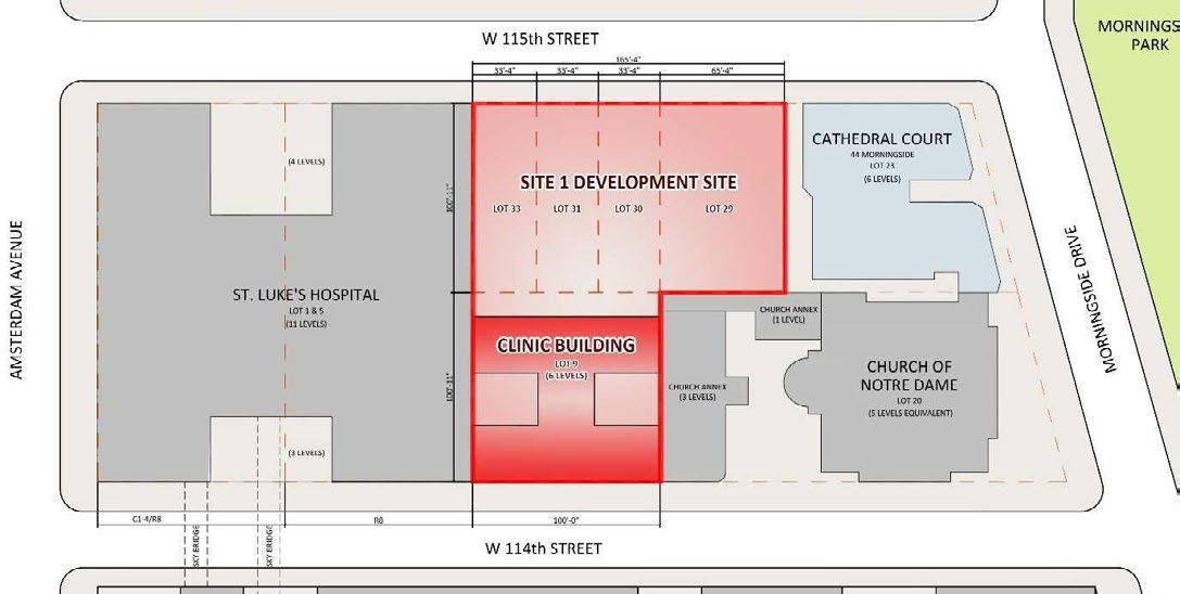

1 R8 as-of-right development, full site, with air rights transfer from 44 Morningside Drive (lot 23) and the Church of Notre Dame (lots 14 and 20)
2. R8 as-of-right development, full site, with air rights transfer from 44 Morningside Drive (lot 23)
3. R8 as-of-right development, full site
4. R8A proposed contextual rezoning development, full site
5. R8 as-of-right development, north lots only
Zoning Scenario One
285, 062 ZFA
As-of-Right, Full Site With Lots 20 & Lot 23 Air Rights Transfer
This scenario was not selected for further study because of the schedule and financial risks associated with the purchase of air rights from the Church of Notre Dame. The use of these air rights would also require approval from the Landmark Preservation Commission as the church and rectory are designated landmarks.
2
Zoning Scenario Two
177,227 ZFA
As-of-Right, Full Site With Lot 23 Air Rights Transfer
This scenario was selected for further study.

285,062 ZFA
Scenario 4
Proposed Contextual Rezoning Full Site


177,227 ZFA
Scenario 5
As of Right North Site

3
Zoning Scenario Three
150,172 ZFA
As-of-Right, Full Site
This scenario was not selected for further study because the air rights from Lot 23 are readily available and expand the programmatic options available to the university for this site.

As of Right North
4
Zoning Scenario Four
150,172 ZFA
Proposed Contextual Rezoning Full Site
150,172
Although the contextual rezoning is only a proposal, it is possible this proposal may eventually be approved. This scenario was selected for further study to understand the limitations rezoning would have on the development potential of this site.
5
Zoning Scenario Five
108,511 ZFA
As-of-Right, North Site only
108,511
This scenario was not selected for further study because the inclusion of the south block provides greater flexibility for the development of the site, especially with regard to the single tower massing. Also, the availability of a site of this scale, inclusive of the south lot, is a rarity this close to the main campus.
Among the many zoning regulations that affect the size and shape of any future development on this site, the rear yard setback soon emerged as a principle factor in the building massing approach. As noted earlier, for the through-block portion of the site, the rear yard requirement could be met in several ways. The conventional approach is a 30’ rear yard at the back of each lot, resulting in a 60’ rear yard at the midway point of the through lot. The resulting massing (Figure 1) is two bars separated by an open court, with one bar along 115th Street and a second bar along 114th Street. Although full lot coverage is allowed at the ground level, for the remaining above grade floors this zoning approach would yield two separate buildings.
However, for the through lot portion of the site, there is an option where the rear yard requirement is met with a 30’ deep rear yard equivalent extending along the full length of each street line. The resulting massing (Figure 2) is a single tower set back from the street on both sides, again with full lot coverage allowed at the ground level. This option requires a 40% lot coverage for the upper floors, but eliminates the sky exposure plane setbacks.
For the proposed contextual rezoning, the rear yard equivalent is not allowed, and only the conventional rear yard setback at the rear of the lot is an option. As a result, the massing approach here is limited to the double bar (Figure 3). This potential rezoning would also introduce a height limit to the bulk regulations, which does not exist in the as-of-right zoning.
For this reason, it is unlikely that the university would be able to use a substantial amount of the air rights transfer available for the site as the height limit will be reached before much, if any, of the transferred rights could be incorporated.
An important aspect of the zoning approach for this site, especially in the as-of-right schemes with air rights transfers, is the use of the 40% tower regulation. Anticipating program requirements that would benefit from the use of repetitive and larger floor plates, it became apparent that working within the sky exposure plane would result in floor plates that are too small to be used effectively. The tower regulations, however, allow for the massing to extend beyond the sky exposure plane when the associated floor plate is less than or equal to 40% of the total lot. Many of the massing and program combinations in the following pages use the 40% tower regulations to accommodate the target program mixes.
Ultimately, through our discussions with Columbia University, it was determined that this study should focus on the following three zoning and massing approaches:
A. R8 as-of-right double bar with air rights transfer from 44 Morningside
B. R8 as-of-right single tower with air rights transfer from 44 Morningside
C. R8A proposed contextual rezoning double bar
Massing Scenario A
R8 as-of-right double bar with air rights transfer from 44 Morningside
Massing Scenario B
R8 as-of-right single tower with air rights transfer from 44 Morningside
Massing Scenario C
R8A proposed contextual rezoning double bar
Lot 9 has previously been included in a zoning lot with Lots 1 & 5 (see 1989 Zoning Lot Description and Ownership Statement). The purpose of this zoning lot merger was to facilitate the transfer of development rights and redevelopment of the hospital. An agreement was entered into in 2002 between St. Luke’s-Roosevelt Hospital and Columbia with regard to potential future development involving the existing zoning lot (see 2002 Zoning Lot Development and Easement Agreement).
This agreement included an allocation of 23,926.5 SF of development rights from Columbia (Lot 9) to the Hospital (Lots 1&5). Because these development rights were transferred and used in the redevelopment of the hospital, Lot 9 cannot be separated from Lots 1 & 5; any future redevelopment involving Lot 9 must also include Lots 1 & 5 in the expanded zoning lot.
The agreement also includes a perpetual setback easement within 30’ of the eastern facade of the hospital building, at a limiting horizontal plane of 198.21’ above Manhattan datum, immediately below the lowest window sill of existing hospital windows (approx. 7th floor of the hospital building).
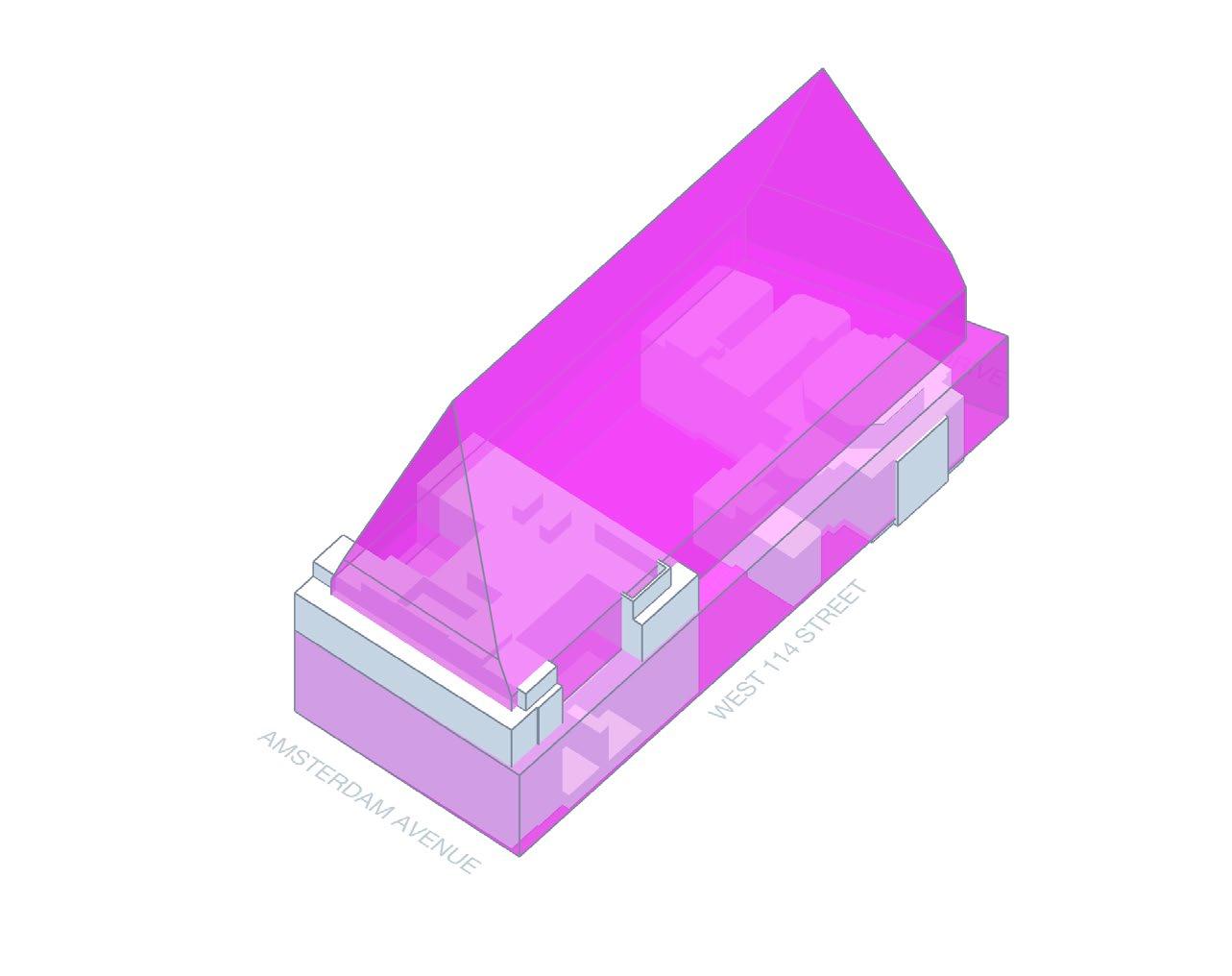
As shown in the image above portions of the existing hospital building (shown in grey) are non-compliant with the minimum setbacks and sky exposure plane. The proposed redevelopment will not increase the degree of this noncompliance, which was previously approved by BSA.
• The redevelopment of the hospital required approvals from the NYC Board of Standards and Appeals.
• #42-88-BZ included a special permit per 73-641 for modifications to rear yard and height and setback requirements, as well as a variance per 72-21 for modifications to lot coverage requirements.
• #1259-88-A included an appeal to allow for lot-line windows on the eastern wall
As shown in the image above, portions of the existing h minimum setbacks and sky exposure plane. The propos degree of this non-compliance, which was previously a Jan 14, 2022
• Because of the existing zoning lot, these prior BSA approvals give the BSA jurisdiction over any future redevelopment involving Lot 9. See section below for more detail on this process.
The zoning lot includes existing buildings that may not comply with the bulk regulations. The Zoning Resolution includes provisions for non-complying buildings that aim to “prevent the creation of additional non-compliances or increases in the degree of existing non-compliances” (51-00).
To calculate available development potential, we cannot increase non-compliance of the lot, but we are not penalized by existing non-compliance. See Appendix for details.
There is one redevelopment scenario that may be permitted as-of-right, without BSA review and approval: development of the north portion of the site (Lots 29-33 only, i.e. excluding Lot 9 or any transfer of development rights). This would be a standard filing with the Department of Buildings.
Transfer of development rights from adjacent lots on the block to the development site requires a zoning lot merger. This requires Zoning Exhibits, signed by all parties in interest for all properties, be prepared by a title company and filed with the Department of Finance and Department of Buildings. These are the official record of the extent and ownership of the zoning lot. Note that similar documents are required to be recorded even for a zoning lot consisting of a single tax lot.
p g documents are required to be recorded even for a zoning lot consisting of a single tax lot
For a zoning lot merger involving multiple tax lots, a Zoning Lot Development Agreement (ZLDA) is typically signed by the property owners and submitted to the Department of Finance This agreement documents each party’s rights and responsibilities for future use and development within the merged zoning lot, for example specifying the allocation of development rights between lots in a table like this (from the existing ZLDA between Columbia and the Hospital):
For a zoning lot merger involving multiple tax lots, a Zoning Lot Development Agreement (ZLDA) is typically signed by the property owners and submitted to the Department of Finance. This agreement documents each party’s rights and responsibilities for future use and development within the merged zoning lot, for example specifying the allocation of

The BSA may allow an application to be filed on its Special Order Calendar (SOC) a the previous BSA approvals involving the hospital. The applicant should request a d the BSA Chair regarding whether the application may be appropriately filed on the S given that the proposed redevelopment is likely to have minimal if any impact on th building. Otherwise, a new application must be filed on the typical BZ calendar.
The BSA may allow an application to be filed on its Special Order Calendar (SOC) as an amendment to the previous BSA approvals involving the hospital. The applicant should request a determination by the BSA Chair regarding whether the application may be appropriately filed on the SOC calendar, given that the proposed redevelopment is likely to have minimal if any impact on the existing hospital building. Otherwise, a new application must be filed on the typical BZ calendar.
Landmarks Preservation Commission
Landmarks Preservation Commission
The Church of Notre Dame (Lot 20) and its rectory (Lot 14) are both designated as In Landmarks. Any redevelopment options involving transfer of development rights fro would require approvals from the Landmarks Preservation Commission.
Board of Standards and Appeals
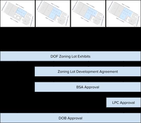
The Church of Notre Dame (Lot 20) and its rectory (Lot 14) are both designated as Individual Landmarks. Any redevelopment options involving transfer of development rights from these lots would require the development to obtain approvals from the Landmarks Preservation Commission. The chart below summarizes the types of filings and approvals that may be required for different development scenarios:
The chart below summarizes the types of filings and approvals that may be required development scenarios:
As discussed in the previous section prior BSA approvals for the hospital redevelopment give the BSA jurisdi with Lots 1
Jan 14, 20
Lots 29, 30, 31, 32 Lots 29, 30, 31, 32, 9 (with 1 and 5)
Lots 29, 30, 31, 32, 9 (with 1 and 5)
23 development rights
Lots 29, 30, 31, 32, 9 (with 1 and 5)
23 development rights
14 & 2 dev. rights
The following table summarizes the lot area and development rights available to the site. Calculations are based on the area of the zoning lot (i.e. all tax lots included as development sites and any tax lots involved in transfer of development rights), and must take into account the combined lot area, existing buildings to remain, and prior transfers of development rights that have occurred between these lots.
• All areas are rounded to the nearest square foot
• Lot area (source: Envelope based on Digital Tax Map & mapPLUTO) should be verified via survey
• Existing building GFA (source: PLUTO) and any ZFA deductions should be verified via survey
• Amount of prior transfer per Exhibit D of 2002 Zoning Lot Development and Easement Agreement
The following tables summarize the lot coverage calculations applicable to the site. Note that the area of existing noncompliance on the Hospital site is excluded from these calculations as it was previously approved via BSA variance.
The following table summarizes the tower lot coverage calculations applicable to the site. A tower is defined as “any portion or portions of buildings which in the aggregate occupy not more than 40 percent of the lot area of a zoning lot” which “may penetrate an established sky exposure plane.” We estimate the existing portion of the Hospital building which penetrates the sky exposure plane to have a footprint of 6,100 SF, this figure should be verified.




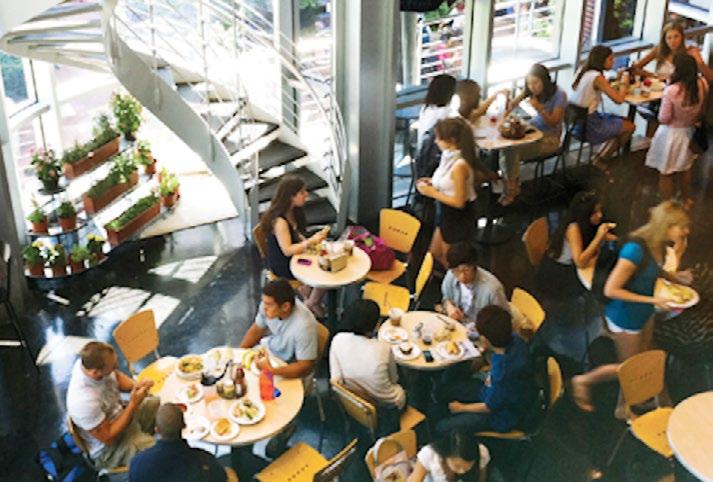
The programs identified for Site 1 were initially identified by the University for further exploration and development in the Study and included undergraduate student residences, an expanded and consolidated Health Services Center, an additional student dining facility and a satellite recreation space. These are all uses that are currently underserved on the campus and their expansion would significantly impact and enhance campus-life. In addition, these programs represent best uses for such a central location, since they serve a campus-wide constituency and benefit from proximity to other undergraduate residences, classrooms and academic spaces. Two of the uses (Health Services and Recreation) had already undergone independent programming and master planning efforts.
On many campuses these programs might occupy separate facilities, however at urban institutions such as Columbia, real estate is a premium and mixed-use buildings are far more common. Although these uses typically operate independently, with their own specific access requirements and security perimeters, there may be potential benefits in their co-location in a single facility. There are beneficial relationships and alignments in their missions, much of which revolves around promoting wellness and the overall quality of student life and learning. Areas for exercise/meditation, kitchen demonstration and teaching, nutrition and health-related education, and informal gathering and learning are examples of spaces that bridge between the four program areas and could contribute to a unified building identity and character.
In addition to the four core program areas, the planning effort identified the need for flexible public space, tentatively titled “Commons.” Unprogrammed social gathering space is in short supply at Columbia and the Commons has been conceived as flexible area for casual interaction, informal study, and even ancillary dining space. Most importantly it can engage the diverse users of the building, promote physical access and connections to and between the major programs, and could be further developed to support a shared mission of wellness and health. This area is intentionally not programmed in high-detail as we believe its opportunities will emerge as part of an overall building design process and resulting plan adjacencies.
The proposed programs for housing and dining used in this study were developed through interviews with departmental staff, review and tours of existing facilities and review/ benchmarking of recent projects at peer institutions in urban settings. The program for Health Services and Recreation were derived from a pre-existing Program Studies (Columbia Health Facility Master Plan 2020 and the Dodge Gym Transformation Program 2018) supplemented by departmental interviews.
Benchmarking examples of recent student residences, with an emphasis on peer institutions in urban settings, were reviewed with departmental staff with attention to the mix of room types (singles/doubles), provisions for shared lounges and study space, relationship to toilet/shower rooms, and the distribution of kitchens and laundry. Benchmarking also looked at net and gross area per bed to assist in establish realistic planning targets. In the development of the student residences and Health Services programming, diagrammatic test-fits were also developed to better understand the dimensional constraints and opportunities of the zoningmandated floorplates and to conform the organization of major components of the program.
Dining Services has been programmed for a new stand-alone 400-seat student dining area with kitchen and servery. The Recreation program envisions a satellite location for student fitness, classes and related lockers/support that supplements, but does not replace existing facilities in Dodge.
Because the proposed site has a fixed capacity for new construction, it is not possible to build as much space as would ideally be provided for all the program uses identified for inclusion. Working with the University, the study has developed a series of alternate scenarios or combinations of programs. The chief variable in the development of the planning options are in the relative sizes of Student Housing and Health Services, as these are the two largest program components and occupy the bulk of the proposed building above the ground floor.
Dining is carried as a single option, primarily as there is a significant fixed space requirement for the kitchen and support space, and reductions in seating count would not effectively reduce overall space requirements in direct proportion. The Recreation program component is also carried as a fixed program area in the combinations. Because it requires its own locker/shower facilities and staffing, there is also an economy of scale here. Both Dining and Recreation spaces can potentially occupy space in the base and lower levels of the building that are less suitable to student housing and health services.
With the review and input of the University, these options were refined into five basic combinations which were tested against the zoning requirements of the site.
The program options for the proposed building are:
• 300-Bed Student Residence, Dining, Health Services (Option 3), and Commons
• 300-Bed Student Residence, Dining, Health Services (Option 1), Recreation, and Commons
• 400-Bed Student Residence, Dining, Health Services (Option 2), and Commons
• 500-Bed Student Residence, Dining, Rec. & Commons
• 600-Bed Student Residence, Dining, and Commons
Additionally, there are three sub-variants of the program options specific to Contextual Zoning, which has a smaller floor area capacity. The program requirements for the building are further defined in the following pages of the report.


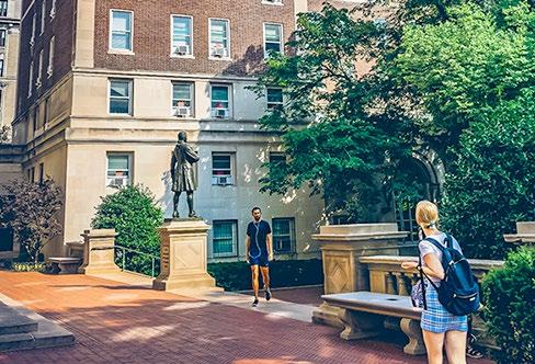
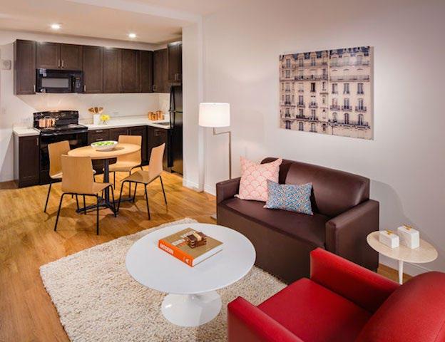



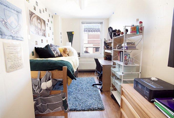

Columbia University has a total of 22 undergraduate residence halls providing a range of housing options and amenities for students. The most prominent dormitories are located along the south lawn of the main campus and form the heart of the freshman community. Undergraduate dormitories are also located along Broadway, on the side streets of the neighborhoods south of the campus, and on the East Campus across Amsterdam Avenue.
University housing is central to the Columbia University undergraduate experience, with many students electing to stay in dormitories throughout their upper-class years despite the availability of alternate housing options nearby. Site 1 offers the university a rare opportunity to expand access to housing for its students and to reconsider oncampus living models at a meaningful scale, comparable to the largest existing dormitories.
As an urban campus, Columbia University has limited space to grow. When the opportunity arises, competing demands for space often require multi-use buildings where various functions are layered together. For this residence hall, this layering of functions is a unique benefit, as the other potential programs sharing this site, health, recreation and dining, are centered around an evolving understanding of wellness and position this project to enhance the quality of student life on campus in a holistic way.
For the development of the residence hall program, the team met regularly with leadership at Columbia University Campus Services, and also studied housing models at peer institutions. The latter studies can be referenced in the benchmarking analysis included in the appendix.
From our discussions we learned that the residence hall at Site 1 would be intended primarily for sophomores, and that the dormitory would need to house 200 students at a minimum (preferably 300) to provide a sense of community and identity. For this study a range of scales from 300 to 600 beds were considered. As a reference, the largest undergraduate dormitory on campus are John Jay at 467 beds and East Campus at 726 beds.
Other metrics of the programming include:
• Housing mix of 75–80% singles, 20–25% doubles
• Student to bathroom ratio of 4 to 1
• One (1) Resident Advisor per 40 students, or one per dormitory floor
• One (1) apartment for a Resident Hall Director
• Kitchens to be shared per floor or provided in conjunction with a full-service dining hall in the building
A primary focus of our study was the scale and relationship of shared spaces in the dormitory. One model found at peer institutions emphasized suite-type dormitory units with private common spaces and bathrooms. At Columbia, there was a concern this approach would internalize student interaction at the expense of fostering stronger communities at a broader scale. As a preferred alternate, other benchmark models were organized around bedrooms and bathrooms directly accessible from shared corridors, with communal spaces of various scales and use distributed at central locations on the floor.
As part of our study, the team developed preliminary test fits. These should be understood as planning instruments to vet assumptions about the metrics of the program implementation. A design would need to be developed further in a later phase of work with continued involvement by Columbia University and their user groups. Our initial test fits suggest a 300 GSF per student bed ratio which is comparable to other dormitories in the benchmarking. The test fits show that the optimal building width to support the desired unit types is between 50’ to 60’. This is narrower than the maximum width of building allowed in some of the zoning scenarios considered, and as a consequence, a housing program might result in a building that does not utilize the full development potential of the site on a floor by floor basis. This will be explained in more detail in the program and building massing scenarios outlined towards the end of this study.
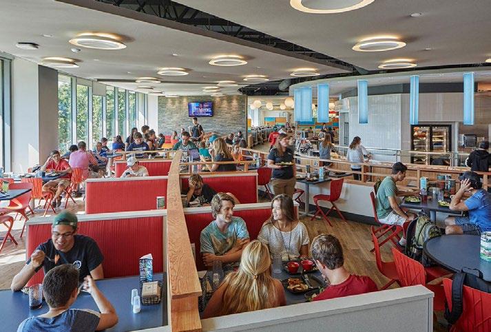


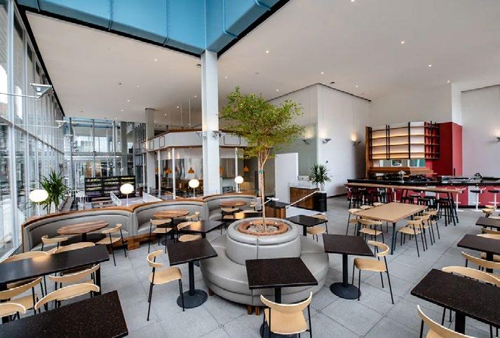
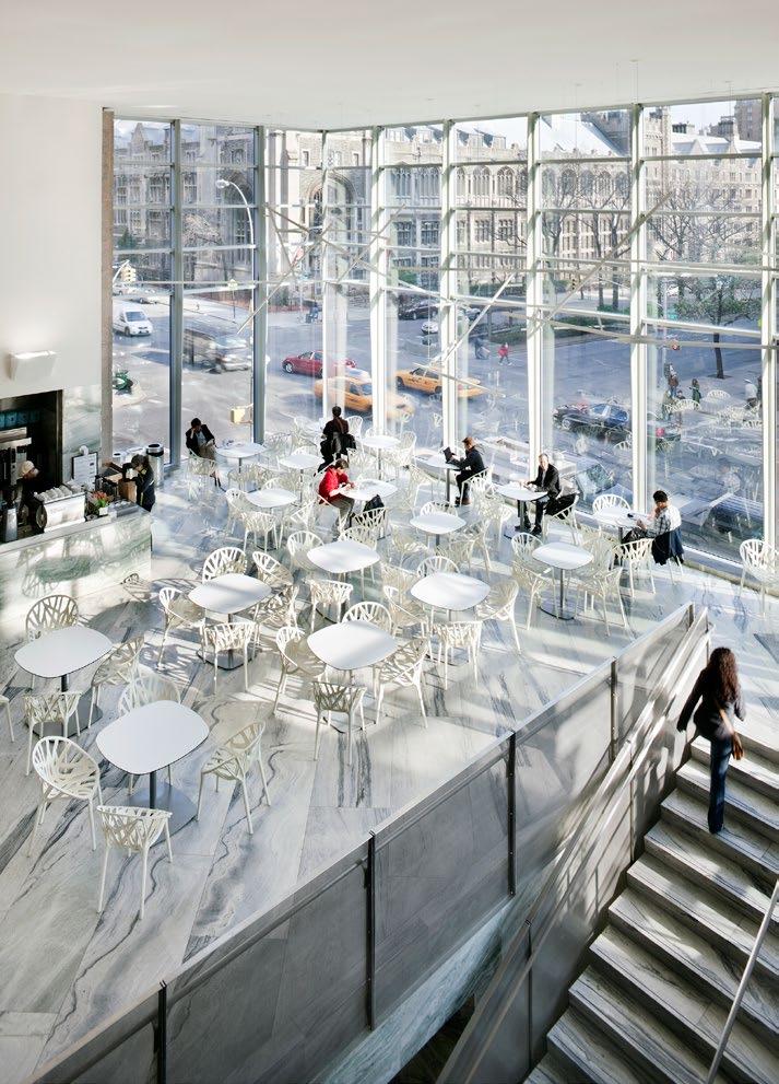


Dining services at Columbia University are an important part of undergraduate student life, despite the availability of kitchens in many of the dormitories and plentiful options for dining out throughout the neighborhood. Columbia Dining serves 12,000 to 14,000 meals a day, structured around 6,800 student meal plans, including 1,500 that are mandatory for first year students. Overall participation is at 81% of the undergraduate student body. Prior to the pandemic, Columbia Dining provided 22 hours of continuous meal operation.
However, as an urban campus, the space allocated for dining services at Columbia University is far less than that of the other peer institutions. Columbia’s 9:1 student-to-seat ratio is more than double that of the other Ivies, which average 4:1. The challenges resulting from a deficiency of available space not only affect seating capacity, but also all other aspects of dining service, from food preparation and serving, to logistics, delivery, and staff support.
Site 1 offers Columbia Dining an excellent opportunity to expand upon its food service offering by providing a home for a new dining hall at a scale consistent with the main dining halls on campus. Although potentially sharing this site with a new dormitory, the dining hall would be scaled to meet campus-wide demands. This is consistent with the food service approach throughout the university, where each dining location is unique in terms of menu but not dedicated to a specific community of students. Over the course of this study, Davis Brody Bond, along with our food service consultant Davella Studios, met with representatives of Columbia Campus Services to better understand the goals for this new dining facility, and have proposed the following concepts for food service and associated space metrics as a guide for future development.
This concept maximizes fresh preparation in an exhibition style format that utilizes small batch production, as well as foods prepared by the main kitchen staff. This approach enhances the customer’s perception of freshness and demystifies the origin of the product.
• In its purest sense the approach is to create mini restaurants or “platforms.” Each platform has its own food production and service format, but with an architecturally coordinated identity. With much of the food preparation and cooking done in front of the customer, preliminary and bulk preparation is supported by the main production kitchen.
• This exhibition servery will bring many of the kitchen functions out of the back of the house, thus visually engaging the customer in the process of preparing and serving food. This creates a dynamic, lively, and interactive environment bridging the areas of food production and product authenticity and customer service.
• Merchandising is another key component to this concept. The use of retail food display equipment as well as retail graphics and lighting will display food in an attractive manner and improve the perceived quality of the products offered.
• Control Points. Access to the all-you-care-to-eat (AYCE) dining program is an important factor during peak lunch and dinner times. Controlling the flow of customers into the space will allow the service points have time to adjust to peak customer surges and maintain consistent flow and customer throughput.
• Dining Areas. Seating areas should incorporate a variety of table styles to include four-tops, communal tables, bar-height and counter height. Additional elements should include self-service beverage stations, condiment stations and trash/recycling disposal counters. Seating layouts should take into consideration late night service and study areas.
• Micro Restaurants. A collection of micro restaurants presented as defined concepts with individual identities and a strong point of view. Each micro restaurant will have the ability to expand and contract in menu and offering based on demand.
• Main Kitchen & Support. Designed to support Commons Food Hall concept. Requires easy access to the loading dock and freight elevators. Infrastructure includes refrigerated and dry storage, hot and cold production, trash and recycling, ware-washing, food service offices and staff facilities.
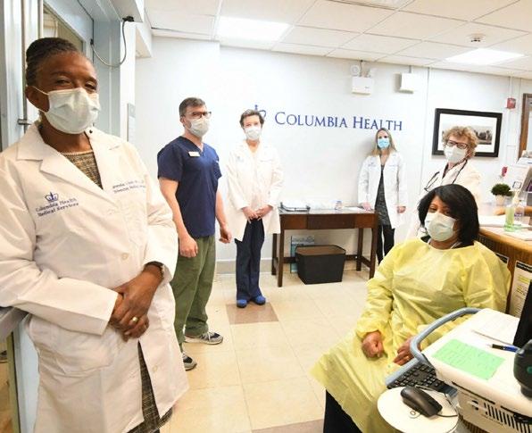
Columbia Health advances the well-being of the university community by delivering medical and counseling services to Columbia University students in support of their personal and academic development. These services are offered through six departments:
• Medical Services
• Counseling & Psychological Services
• Disability Services
• Sexual Violence Response
• Alice! Health Promotion
• Administration
Columbia Health services are currently distributed across six locations on campus, in facilities that are over-utilized and outdated. Many of these were built for other functions and have been repurposed over time. As a consequence, they do not adequately support the quality of medical services
Columbia Health aspires to provide its students, nor can they address the growing demand for health services on campus. In particular, it is a challenge to provide care for students who would benefit from a more integrated approach when different services are located separately from one another across campus.
In 2020, Columbia University engaged the services of Ewing Cole to develop a master plan and programming study for Columbia Health. This was a first step towards the goal of co-locating all of Columbia Health in one facility sized to accommodate the growing demand and evolving models for health services on campus. The master plan addresses the following general issues:
• Space type and allocation that do not currently conform to industry standards for health care services
• Demand increase based on growing utilization trends for health services.
• Demand increase from anticipated growth in the Columbia University enrollment
• New programs to align Columbia Health services with evolving health care models
The Ewing Cole study maps out the following growth scenarios to address these demands:
• Right-sized, No Growth
• 2030 Growth
• 2045 Growth
For this study, Davis Brody Bond was asked to update the 2020 Master Plan program, and to study how the various Columbia Health Growth scenarios can be accommodated in Site 1. Relative to the development potential for Site 1, the program growth scenarios for Columbia Health in the 2020 study were significant in their size, and as defined would limit the opportunities for a multi-use building that could be shared with a residence hall. This was especially true for the 2030 and 2045 growth options. With the aim of preserving a shared programming for Site 1, we were asked to include along with the Right-sized No Growth program two new and smaller program options. Together the three options under consideration for this study are:
• Health 1: 2030 Medical Services
• Health 2: 2030 Medical Services, Alice! Health Promotion and Administration
• Health 3: Current Program, Right-sized
These program options are built around Medical Services because the requirements for these spaces are the most specialized, and the current facilities in John Jay fall short of these standards. Also, the space that would be made available in John Jay if Medical Services were relocated represents an excellent opportunity for strengthening the existing programing in that building, one that would be hard to come by so close to the heart of the campus.
The 2020 programming was conducted during the COVID-19 pandemic, but the metrics for that programming were based on pre-pandemic health service models. In our discussions with Columbia Health leadership, it was important to understand how the pandemic had changed the ways Columbia Health provided services to its students and what types of spaces would be needed to support these new service models. Contrary to expectations, we learned that although there has been an increase in the use of the telemedicine, there was no corresponding change in overall space needs.
The primary program adjustments from 2020 instead resulted from the restructuring of Columbia Health as a university department separate from Campus Services. This resulted in a modest increase of administrative spaces to accommodate previously shared positions. Other potential adjustments to the 2020 program are related to the check-in and waiting room strategy for Medical Services and Counseling. The precise modifications to the program cannot be quantified at this time, but will be a response to the way in which the space allocation for these services will be divided across multiple floors. Similarly, there may need to be some re-allocation of ready-supply storage for multiple floors. The Ewing Cole program presumed larger floor plates that will not be possible on Site 1, and the areas assigned to the entry sequence (and possibly storage)will need to be expanded to accommodate some repetition of functionality over a greater number of floors.
Lastly, during the 2020 programming, there was an interest in sharing Counseling and Medical Services on the same floor to avoid situations where students seeking psychological support can be identified by the floor they are visiting. Upon review of the floor sizes we anticipate at Site 1, Columbia Health is moving away from this approach, in favor of the efficiencies afforded by floors with dedicated programs.

Campus Recreation and Physical Education is co-located with Columbia Athletics in the Dodge Fitness Center, and together are part of a single organization. The Dodge Fitness Center consists of two original buildings beneath Pupin Plaza that are over 100 years old, connected by a structure housing the main gym built in 1974. This grouping was developed to support an athletics program that was much smaller in size, serving an undergraduate population that was all male. By the time organized women’s sports were added to Columbia Athletics, following the introduction of co-education in 1983, this facility was fundamentally undersized.
Columbia Athletics has continued to grow and now fields 31 Men’s and Women’s intercollegiate Division 1 NCAA teams. The opening of Campbell Sports Center at Baker Field in 2012 has provided modern facilities and much-needed relief for the space demands at Dodge, but this has been overcome by an increase in utilization for Campus Recreation. Student enrollment growth has also increased demands for space, especially because Columbia Recreation includes Physical Education, which offers programs that are part of the graduation requirement for Columbia undergraduates.
As an alternative to Dodge Fitness Center, where campus recreation competes for space with intercollegiate Athletics and Physical Education programming, Site 1 offers an opportunity for a customized satellite facility that is focused solely on recreation. As such it also invites a new way of thinking about the purpose and goals of recreation programming on campus.
In discussions with Campus Recreation user groups, there was an interest in moving away from traditional recreational programming and instead focusing on an integrated approach to meeting the well-being needs of the student community. This can involve working in partnership with other university departments and entails re-centering physical recreation as a contributor to emotional health and personal development.
The spaces identified for this program include:
• Cardio Area (approx. 12,500 to 17,000 sf)
• Strength Training Area (approx. 14,000 to 17,000 sf)
• Multi-Purpose Spaces (7,500 to 10,000 sf)
• Staff (3 to 4 professional staff / 2 offices, custodial and security)
• Locker Rooms, Shower, and Changing Rooms (gender inclusive)
• Equipment Rooms

From the early phases of the project, it became clear that the greatest potential for Site 1 was not in the individual programs that would be housed there, but in their collocation. This is especially true because the uses anticipated for Site 1 could all support a more holistic approach to student wellbeing if understood together. When we started to look at the program combinations for Site 1, it became clear that we also needed to build in a space that would be open for shared activities, a space that was not owned by any particular program but instead shared by all. For the purposes of the study we allocated 5000 GSF for the shared commons, and we understand this space as integral to the sequence of entry and access to the other programs on site.
The diagrams on this spread show our preliminary ideas about the shared commons mapped onto the double bar and single tower zoning scenarios.
Entry Level Section
R8: Double Bar
R8A: Contextual
Based on our previous understanding of the site and its relationship to the main campus, we see the main entrance located on 115th Street, with possible connections south to a secondary entrance on 114th. In both scenarios, the shared spaces are located in areas where zoning requires open space on the second floor, ensuring that these spaces could have skylights and access to natural light from above.
The commons would provide access to separate circulation cores when required by the program, each with dedicated security if needed. In the double bar scenario, the cores are divided naturally. In the single tower, we anticipate a satellite core at the eastern end to serve the lower floors and a central core to serve the upper floors. In both scenarios, the commons allows for a ground floor organization that combines shared spaces and dedicated entries. There are also ways of thinking about the commons vertically as a connection between the ground floor, the lower level, and shared amenity spaces on the second floor which have the potential for direct access to rooftop outdoor space.
COMMONS
COMMONS Entry
COMMONS Entry
Shared Spaces Options
These following test fits were developed as part of our programming study to understand the basic organization of the dormitory from a planning perspective, and to develop optimal building widths for the massing studies. These test fits align with the 300 GSF/bed programing ratio that we have seen in the benchmarking studies of dormitories at similar institutions.
Spaces Options
Beds Per Floor: 23
Single Beds: 16
Double Beds: 6
RA Beds: 1
Floor Plate Area: 7,000 SF
SINGLE TOWER Shared Spaces Options
Beds Per Floor: 29
Beds Per Floor: 23
Single Beds: 22
Double Beds: 6
RA
Single Beds: 16
Double Beds: 6
1
RA
These building organization diagrams were developed to provide a broad understanding of the health program fit with respect to the double bar and tower massing options. Although diagrammatic, these are based on the clinical pod unit for medical services as defined in the 2020 Master Plan. The clinical pod is the basic organizational unit of the Medical Services program and is a good test for the viability of the health program fit in general. In the double bar, the north tower is close to fitting two clinical pods on one floor.
These floor plates are limited to the lowest levels below the 30’ light and air easement from the adjacent hospital. The south bar, however, is not adequately sized to support one clinical pod without adjustment to the program. The tower floor plan is larger and can accommodate two clinical pods with additional space for other programming as needed

The following pages illustrate program and massing combinations that together define a range of options for the development of Site 1. The three massing options were derived from the considerations outlined previously in the zoning study, and the eight program mixes were selected from a broader range of options to align institutional priorities with the development potential of the site.
The programs under consideration for this site — residential, health, recreation and dining — offer Columbia University an opportunity to develop Site 1 as a place that supports a holistic approach to student well-being. The selection of these programs for potential inclusion in Site 1 show a willingness to question the conventional divisions between where students live, what they eat, how they spend their time and how they care for themselves in favor of a more comprehensive way to support student life on campus. However, as a totality the programs under consideration exceed the development potential for the site, especially when considering the larger ranges of options for housing and health. As a first step, this study involved laying out viable combinations that worked within the zoning limits, and then selecting from those a smaller subset to test against the building massing options.
In summary, these are the range of scales for each program type that were selected for the massing studies in the following pages.
• Residence Hall. All program mixes under consideration have housing as a primary program, with a range of 300-600 beds.
• Dining. For a relatively small allocation of space there is an opportunity to address in a significant way the need for additional dining on campus. All program mixes under consideration include a 400-seat dining hall.
• Shared Commons. An allocation of 5000 GSF is included in all program mixes for a shared common space. This open program enhances and supports the building as a multi-use facility. The shared commons provides a social and physical framework by which other building uses are accessed and organized. More importantly, evolving programs in support of student wellness that arise from collaborations between the various groups in this building can use the shared commons as a home.
• Health. The health programs selected for these massing studies include:
– Health 3: the Right-sized No Growth program from the 2020 Ewing Cole Master Plan
– Health 2: 2030 Medical Services with Alice! Health Promotion and Admin
– Health 1: 2030 Medical Services only
Health 2 and Health 1 are smaller options that were added to support the multi-use programming that is intended for Site 1. All three scenarios will retain existing spaces on campus for the departments that are not relocating.
• Recreation. A student well-being recreation center with multi-purpose spaces, cardio and strengthening studios has been included in the program mixes under consideration.
The massing and program scenarios that follow are based on one of the following three options:
A. R8 As-of-right with Air Rights Transfer; Double Bar
B. R8 As-of-right with Air Rights Transfer; Single Tower
C. R8A Proposed Contextual Rezoning
The scenarios are given numerical scores based on the following evaluation criteria:
• Urban Design (15%). Relationship of building mass and scale to neighboring structures, service loading and public street frontages, and visual connections to campus & park
• Image + Identity (10%). Image Public program uses, access/ visibility on 115th, pedestrian connections to main campus.
• Program Accommodation (35%). Operational efficiencies for staffing & shared spaces based on floorplate size.
• Building Efficiency (20%). Additional gross area to accommodate higher proportion of circulation on smaller floorplates, additional egress stairs, duplication of toilets and support facilities, and some program duplication to function on multiple smaller floorplates.
• Cost (15%). Premiums for add’l building envelope relative to floor area, additional elevators and main HVA distribution lines, plumbing fixtures in two building massings.
• Approvals Process (5%). Requirements for special approval processes; DOB and BSA.
Massing Scheme A: As-of-Right Base Option Program: 600 Student Beds, Dining
*For lot coverage and tower lot coverage calculations, see zoning calculations on page 26–27.
EVALUATION SUMMARY (6.9 Total Score)
• Neighborhood Context: 8
The double bar massing is consistent with the continuous street walls along 114th Street and 115th Street.
• Image and Identity: 8
The building has a strong presence along 115th, reinforcing connections to campus. The inner courtyard provides a setting for shared program activities.
• Program Accommodation: 8
Preliminary test fits show that this scenario supports a 300 GSF/bed ratio consistent with the benchmarking studies.
• Building Efficiency: 5
Double bar massing results in a lower net to gross area ratio.
• Cost: 5
Duplication of building cores and envelope is likely a cost increase over a comparable single tower scenario.
• Regulatory Path: 5
The same for all scenarios under consideration.
This scenario is based on the as-of-right zoning with an air rights transfer from 44 Morningside Drive. The massing is organized as two separate bar buildings, one along 114th Street and one along 115th Street, both above a ground floor that covers the full lot. This scenario assumes one below-grade level also covering the full extent of the lot.
The programming for this scenario includes a residential hall with 600 beds, which is the largest dormitory under consideration in this study. There is also a dining hall with 400 seats, and a shared commons space
Although the ground floor is shared, the residence hall would be split between two buildings, each with a separate circulation core which could have dedicated secured entrances. In this scenario, the housing block at the north is 50’ deep to align with our preliminary test fits. The housing block to the south is deeper at 70’ to maximize the development potential of the narrow site. This may be an opportunity to consider different identities for the two housing blocks, with a typical dormitory of single and double bedrooms at the north tower, and apartment type suites utilizing the deeper floor plates at the south. An amenity floor with communal functions may be located on the second floor, organized around the open rear-yard court separating the two tower blocks.
Because the residence hall program benefits from the efficiency of a typical repetitive floor plan, this massing uses the 40% tower regulations for the north block to avoid the setbacks that would be required to stay within the sky exposure plane.
*For lot coverage and tower lot coverage calculations, see zoning calculations on page 26–27.
EVALUATION SUMMARY (6.8 Total Score)
• Neighborhood Context: 8
The double bar massing is consistent with the continuous street walls along 114th Street and 115th Street.
• Image and Identity: 8
The building has a strong presence along 115th, reinforcing connections to campus. The inner courtyard provides a setting for shared program activities.
• Program Accommodation: 8
Preliminary test fits show that this scenario supports a 300 GSF/bed ratio consistent with the benchmarking studies.
• Building Efficiency: 5
Double bar massing results in a lower net to gross area ratio.
• Cost: 5
Duplication of building cores and envelope is likely a cost increase over a comparable single tower scenario.
• Regulatory Path: 5
The same for all scenarios under consideration.
This scenario is based on the as-of-right zoning with an air rights transfer from 44 Morningside Drive. The massing is organized as two separate bar buildings, one along 114th Street and one along 115th Street, both above a ground floor that covers the full lot. This scenario assumes one below-grade level also covering the full extent of the lot.
The programming for this scenario includes a residential hall with 500 beds, a dining hall with 400 seats, a well-being recreation center, and a shared commons space.
Although the ground floor is shared, the residence hall would be split between two buildings, each with a separate circulation core which could have dedicated secured entrances. This may be an opportunity to consider different identities for the two blocks, with a typical dormitory of single and double bedrooms at the north tower, and apartment type suites on the upper levels of the deeper floor plates at the south.
A well-being recreation center is located on the lower three floors of the south block, with the potential for shared programming between recreation and the residence hall on the second-floor spaces, organized around the open rear-yard court separating the two tower blocks.
Because the residence hall program benefits from the efficiency of a typical repetitive floor plan, we are using the 40% tower regulations for the north block to avoid the setbacks that would be required to stay within the sky exposure plane.
*For lot coverage and tower lot coverage calculations, see zoning calculations on page 26–27.
EVALUATION SUMMARY (4.4 Total Score)
• Neighborhood Context: 6
Double bar massing supports a continuous street wall along 114th Street & 115th Street, however the larger health program and the higher floor to floors results in taller buildings overall.
• Image and Identity: 8
The building has a strong presence along 115th, reinforcing connections to campus. The inner courtyard provides a setting for shared program activities.
• Program Accommodation: 4
The health program would benefit from larger and fewer floor plates than what is provided in this scenario
• Building Efficiency: 3
The double bar massing results in a lower net to gross area ratio, especially for the health program.
• Cost: 5
Duplication of building cores and envelope is likely a cost increase over a comparable single tower scenario.
• Regulatory Path: 5
The same for all scenarios under consideration.
This scenario is based on the as-of-right zoning with an air rights transfer from 44 Morningside Drive. The massing is organized as two separate bar buildings, one along 114th Street and one along 115th Street, both above a ground floor that covers the full lot. This scenario assumes one below-grade level also covering the full extent of the lot.
The programming for this scenario includes a residential hall with 400 beds, a dining hall with 400 seats, a health facility with medical services, health promotion and admin spaces (Health 2), and a shared commons space.
Although the ground floor is shared, the residence hall and the health facility would be split between two buildings, each with a separate circulation core with dedicated secured entrances. In general, the available floor plates at the south block are smaller than optimal for the health facility program, which would benefit from fewer, larger floors. To house the selected health program, eleven stories are required in this scenario.
Because the residence hall and health services program benefit from the efficiency of a consistent floor plan, we are using the 40% tower regulations for the north and south blocks to avoid the setbacks that would be required to stay within the sky exposure plane.
*For lot coverage and tower lot coverage calculations, see zoning calculations on page 26–27.
EVALUATION SUMMARY (4.7 Total Score)
• Neighborhood Context: 6
The double bar massing supports a continuous street wall along 114th Street & 115th Street, however the larger health program and higher floor to floors result in taller buildings overall.
• Image and Identity: 8
The building has a strong presence along 115th, reinforcing connections to campus. The inner courtyard provides a setting for shared program activities.
• Program Accommodation: 4
The health program would benefit from larger and fewer floor plates than what is provided in this scenario
• Building Efficiency: 3
The double bar massing results in a lower net to gross area ratio, especially for the health program.
• Cost: 5
Duplication of building cores and envelope is likely a cost increase over a comparable single tower scenario.
• Regulatory Path: 5
The same for all scenarios under consideration.
This scenario is based on the as-of-right zoning with an air rights transfer from 44 Morningside Drive. The massing is organized as two separate bar buildings, one along 114th Street and one along 115th Street, both above a ground floor that covers the full lot. This scenario assumes one below-grade level also covering the full extent of the lot.
The programming for this scenario includes a residential hall with 300 beds, a dining hall with 400 seats, a health facility with medical services (Health 1), a well-being recreation center, and a shared commons space. Although the ground floor is shared, the residence hall and the health facility would be split between two buildings, each with a separate circulation core with dedicated secured entrances.
In general, the available floor plates at the south block are smaller than optimal for the health facility program, which would benefit from fewer, larger floors. To house the selected health program, thirteen stories are required in this scenario. Because the residence hall and health services program benefit from the efficiency of a consistent floor plan, we are using the 40% tower regulations for the north and south blocks to avoid the setbacks that would be required to stay within the sky exposure plane.
Zoning R8 As-of-right with air rights transfer
*For lot coverage and tower lot coverage calculations, see zoning calculations on page 26–27.
EVALUATION SUMMARY (5.1 Total Score)
• Neighborhood Context: 6
The double bar massing supports a continuous street wall along 114th Street & 115th Street, however the larger health program and the higher floor to floors results in taller buildings overall.
• Image and Identity: 6
The building has a strong presence along 115th, but this frontage is given to health instead of housing. The inner courtyard provides a setting for shared program activities.
• Program Accommodation: 5
The health program fit is better in the north bar, however, there would still be a benefit from larger and fewer floor plates than what is provided in this scenario.
• Building Efficiency: 4
The double bar massing results in a lower net to gross area ratio, especially for the health program.
• Cost: 5
Duplication of building cores and envelope is likely a cost increase over a comparable single tower scenario.
• Regulatory Path: 5
The same for all scenarios under consideration.
This scenario is based on the as-of-right zoning with an air rights transfer from 44 Morningside Drive. The massing is organized as two separate bar buildings, one along 114th Street and one along 115th Street, both above a ground floor that covers the full lot. This scenario assumes one below-grade level also covering the full extent of the lot.
The programming for this scenario co-locates all the health services on campus in one building, right-sized to meet 2022 requirements (Health 3). This scenario also includes a residential hall with 300 beds, a dining hall with 400 seats, and a shared commons space. Although the ground floor is shared, the residence hall and the health facility would be split between two buildings, each with a separate circulation core with dedicated secured entrances.
In general, the available floor areas for health in this scenario improve upon those in other scenarios with two buildings, but are smaller than optimal for the health facility program, which would benefit from fewer, larger floors. To co-locate all right-sized health services, thirteen stories are required in this scenario.
Because the residence hall and health services program benefit from the efficiency of a consistent floor plan, we are using the 40% tower regulations for the north and south blocks to avoid the setbacks that would be required to stay within the sky exposure plane.
*For lot coverage and tower lot coverage calculations, see zoning calculations on page 26–27.
EVALUATION SUMMARY (6.7 Total Score)
• Neighborhood Context: 3
The tower massing may be considered inconsistent with the urbanistic qualities of the surrounding neighborhood where continuous street walls are more common.
• Image and Identity: 5
The building image would benefit from a stronger presence on 115th Street. The tower massing does not provide a natural location for shared programming.
• Program Accommodation: 8
The tower massing is well suited to accommodate all of the program mixes selected in these scenarios.
• Building Efficiency: 8
The tower massing is fairly efficient in terms of net to gross floor areas.
• Cost: 7
The tower massing allows for a more efficient building core and envelope to area ratio which should result in a cost savings over the double bar scenarios.
• Regulatory Path: 5
The same for all scenarios under consideration.
This scenario is based on the as-of-right zoning with an air rights transfer from 44 Morningside Drive. The massing is organized as a single tower with a rear yard equivalent setback along 114th Street and 115th Street for the through block portion of the site. As allowed by zoning, there is a ground floor that covers the full lot. This scenario assumes one below-grade level also covering the full extent of the lot.
The programming for this scenario includes a residential hall with 600 beds, which is the largest dormitory under consideration in this study. There is also a dining hall with 400 seats, and a shared commons space
The single tower massing accommodates the residential program in a straightforward way. The 60’ wide floor plate is less than the 70’ width allowed by the zoning, but is optimized to work with the dormitory program as shown in our preliminary test fits. The resulting tower occupies less than 40% of the lot, allowing for the use of the 40% tower regulations and thereby avoiding the setbacks at the upper floors that would be required to stay within the sky exposure plane. As a result, the tower can be a simple extrusion, with typical floors repeated as needed until the development rights for the site are fully utilized. The tower massing can also take advantage of open eastern views on its upper levels.
*For lot coverage and tower lot coverage calculations, see zoning calculations on page 26–27.
EVALUATION
• Neighborhood Context: 3
The tower massing may be considered inconsistent with the urbanistic qualities of the surrounding neighborhood where continuous street walls are more common.
• Image and Identity: 5
The building image would benefit from a stronger presence on 115th Street. The tower massing does not provide a natural location for shared programming.
• Program Accommodation: 8
The tower massing is well suited to accommodate all of the program mixes selected in these scenarios.
• Building Efficiency: 8
The tower massing is fairly efficient in terms of net to gross floor areas.
• Cost: 7
The tower massing allows for a more efficient building core and envelope to area ratio which should result in a cost savings over the double bar scenarios.
• Regulatory Path: 5
The same for all scenarios under consideration.
This scenario is based on the as-of-right zoning with an air rights transfer from 44 Morningside Drive. The massing is organized as a single tower with a rear yard equivalent setback along 114th Street and 115th Street for the through block portion of the site. As allowed by zoning, there is a ground floor that covers the full lot. This scenario assumes one below-grade level also covering the full extent of the lot.
The programming for this scenario includes a residential hall with 500 beds, a dining hall with 400 seats, a well-being recreation center, and a shared commons space.
The single tower massing accommodates the residential program in a straightforward way. The 60’ wide floor plate is less than the 70’ width allowed by the zoning, but is optimized to work with the dormitory program as shown in our preliminary test fits. The resulting tower occupies less than 40% of the lot, allowing for the use of the 40% tower regulations and thereby avoiding the setbacks at the upper floors that would be required to stay within the sky exposure plane. As a result, the tower can be a simple extrusion, with typical floors repeated as needed until the development rights for the site are fully utilized.
Massing Scheme B: As-of-Right Single Tower Option Program: 400 Student Beds, Dining, Health Med +
R8 As-of-right with air rights
*For lot coverage and tower lot coverage calculations, see zoning calculations on page 26–27.
• Neighborhood Context: 4
The massing along the eastern portion of the lot is more consistent with the urbanistic qualities of the surrounding neighborhood where continuous street walls are more common.
• Image and Identity: 5
The building image would benefit from a stronger presence on 115th Street. The tower massing does not provide a natural location for shared programming.
• Program Accommodation: 8
The tower massing is well suited to accommodate all of the program mixes selected in these scenarios.
• Building Efficiency: 8
• The tower massing is fairly efficient in terms of net to gross floor areas.
• Cost: 7
The tower massing allows for a more efficient building core and envelope to area ratio which should result in a cost savings over the double bar scenarios.
• Regulatory Path: 5
The same for all scenarios under consideration.
This scenario is based on the as-of-right zoning with an air rights transfer from 44 Morningside Drive. The massing is organized as a single tower with a rear yard equivalent setback along 114th and 115th Street for the through block portion of the site. As allowed by zoning, there is a ground floor that covers the full lot. This scenario assumes one below-grade level also covering the full extent of the lot.
The programming for this scenario includes a residential hall with 400 beds, a dining hall with 400 seats, a health facility with medical services, health promotion and admin spaces (Health 2), and a shared commons space.
The single tower massing accommodates the program in a straightforward way. The 60’ wide floor plate is less than the 70’ width allowed by the zoning, but is optimized to work with the dormitory program as shown in our preliminary test fits. The resulting tower occupies less than 40% of the lot, allowing for the use of the 40% tower regulations and thereby avoiding the setbacks at the upper floors that would be required to stay within the sky exposure plane.
To the east of the main tower, there is an adjacent block facing 115th Street. This block can have a dedicated circulation core for health separate from the tower core serving the dormitory. However, it also creates a larger floor plate on the lower levels of the building, which can be effectively utilized by Health Services and result in fewer floors than under Scenario A.
*For lot coverage and tower lot coverage calculations, see zoning calculations on page 26–27.
EVALUATION SUMMARY (7.0 Total Score)
• Neighborhood Context: 5
The massing along the eastern portion of the lot is more consistent with the urbanistic qualities of the surrounding neighborhood where continuous street walls are more common.
• Image and Identity: 5
The building image would benefit from a stronger presence on 115th Street. The tower massing does not provide a natural location for shared programming.
• Program Accommodation: 8
The tower massing is well suited to accommodate all of the program mixes selected in these scenarios.
• Building Efficiency: 8
The tower massing is fairly efficient in terms of net to gross floor areas.
• Cost: 7
The tower massing allows for a more efficient building core and envelope to area ratio which should result in a cost savings over the double bar scenarios.
• Regulatory Path: 5
The same for all scenarios under consideration.
This scenario is based on the as-of-right zoning with an air rights transfer from 44 Morningside Drive. The massing is organized as a single tower with a rear yard equivalent setback along 114th Street and 115th Street for the through block portion of the site. As allowed by zoning, there is a ground floor that covers the full lot. This scenario assumes one below-grade level also covering the full extent of the lot.
The programming for this scenario includes a residential hall with 300 beds, a dining hall with 400 seats, a health facility with medical services (Health 1), a well-being recreation center, and a shared commons space.
The single tower massing accommodates the program in a straightforward way. The 60’ wide floor plate is less than the 70’ width allowed by the zoning, but is optimized to work with the dormitory program as shown in our preliminary test fits. The resulting tower occupies less than 40% of the lot, allowing for the use of the 40% tower regulations and thereby avoiding the setbacks at the upper floors that would be required to stay within the sky exposure plane. The lower six floors are dedicated for recreation and health, and the upper eleven floors for the dormitory.
Massing Scheme B: As-of-Right Single Tower Option Program: 300 Student Beds, Dining, Health Right-sized
*For lot coverage and tower lot coverage calculations, see zoning calculations on page 26–27.
EVALUATION SUMMARY (7.0 Total Score)
• Neighborhood Context: 5
The massing along the eastern portion of the lot is more consistent with the urbanistic qualities of the surrounding neighborhood where continuous street walls are more common.
• Image and Identity: 5
The building image would benefit from a stronger presence on 115th Street. The tower massing does not provide a natural location for shared programming.
• Program Accommodation: 8
The tower massing is well suited to accommodate all of the program mixes selected in these scenarios.
• Building Efficiency: 8
The tower massing is fairly efficient in terms of net to gross floor areas.
• Cost: 7
The tower massing allows for a more efficient building core and envelope to area ratio which should result in a cost savings over the double bar scenarios.
• Regulatory Path: 5
The same for all scenarios under consideration.
This scenario is based on the as-of-right zoning with an air rights transfer from 44 Morningside Drive. The massing is organized as a single tower with a rear yard equivalent setback along 114th Street and 115th Street for the through block portion of the site. As allowed by zoning, there is a ground floor that covers the full lot. This scenario assumes one below-grade level also covering the full extent of the lot.
The programming for this scenario co-locates all the health services on campus in one building, right-sized to meet current standards and health service models (Health 3). This scenario also includes a residential hall with 300 beds, a dining hall with 400 seats, and a shared commons space.
The single tower massing accommodates the program in a straightforward way. The 60’ wide floor plate is less than the 70’ width allowed by the zoning, but is optimized to work with the dormitory program as shown in our preliminary test fits. The resulting tower occupies less than 40% of the lot, allowing for the use of the 40% tower regulations and thereby avoiding the setbacks at the upper floors that would be required to stay within the sky exposure plane.
The tower scenario is particularly beneficial for the largest Health Services Program Option, essentially providingin six floors the spaces that need 12 floors under Scenario A.
(15%)
(20%) COST(15%)APPROVALS PROCESS(5%) TOTALSCORE

The program and massing scenarios on the following pages (Scenarios C.6, C.7, and C.8) are based on a proposed contextual rezoning for the site. As such, these are not possible under current zoning and are not viable options. However, these scenarios illustrate the impact of the proposed rezoning if it were enacted, and so are important as part of this study. In general, the program options that have been accommodated are parallel to those in the as-of-right scenarios, but there is a reduction of 100 beds in the dormitory to account for the height limit in the proposed rezoning and the consequent loss of development potential.



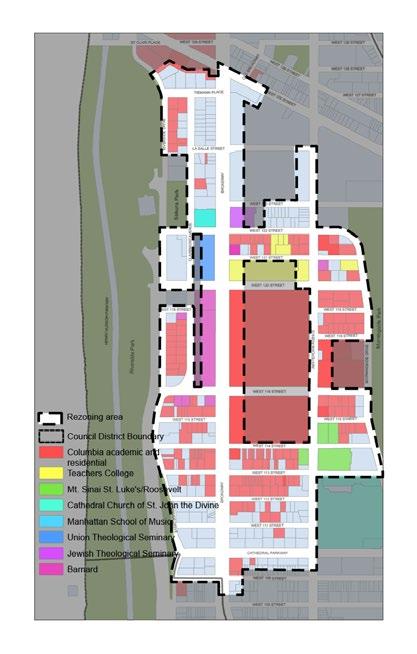

*For lot coverage and tower lot coverage calculations, see zoning calculations on page 26–27.
• Neighborhood Context: 8
The double bar massing is consistent with the continuous street walls along 114th Street and 115th Street.
• Image and Identity: 8
The building has a strong presence along 115th, reinforcing connections to campus. The inner courtyard provides a setting for shared program activities.
• Program Accommodation: 6
The height limit under the proposed rezoning would result in a 100 bed reduction to the dormitory when compared to the associated program mix in the A.1 as-of-right scenario.
• Building Efficiency: 5
Double bar massing results in a lower net to gross area ratio.
• Cost: 5
Duplication of building cores and envelope is likely a cost increase over a comparable single tower scenario.
• Regulatory Path: 5
The same for all scenarios under consideration.
This scenario is based on the proposed contextual rezoning of this site from R8 to R8A, which requires a conventional rear yard as there are no rear-yard equivalents for through lots in the proposed rezoning. Consequently, the massing is organized as two separate bar buildings, one along 114th Street and one along 115th Street, both above a ground floor that covers the full lot. This scenario assumes one below-grade level also covering the full extent of the lot. The proposed rezoning imposes a 125’ height limit for the site, and because of this, there will be limited opportunity to use air rights transfers from adjacent lots. For this study, the development potential is based on the FAR for this site only.
The programming for this scenario includes a residential hall with 500 beds, which is a 100 bed reduction from the corresponding full dormitory program in the as-of-right schemes. There is also a dining hall with 400 seats, and a shared commons space. As with all scenarios in our study, the dining hall and the shared commons provide places for social gathering prominently located at the entry level and at the level below, potentially connected by double-height spaces.
Although the ground floor is shared, the residence hall would be split between two buildings, each with a separate circulation core which could have dedicated secured entrances. Given the height restriction, the housing blocks are deeper than in our preliminary test fits to maximize the development potential and may be better suited for apartment type suites. It may also result in a slightly less efficient area/bed ratio than the 300 sf/bed ratio that has been used in the non-contextual massing options.
*For lot coverage and tower lot coverage calculations, see zoning calculations on page 26–27.
• Neighborhood Context: 8
The double bar massing is consistent with the continuous street walls along 114th Street and 115th Street.
• Image and Identity: 8
The building has a strong presence along 115th, reinforcing connections to campus. The inner courtyard provides a setting for shared program activities.
• Program Accommodation: 6
The height limit under the proposed rezoning would result in a 100 bed reduction to the dormitory when compared to the associated program mix in the A.2 as-of-right scenario.
• Building Efficiency: 5
Double bar massing results in a lower net to gross area ratio.
• Cost: 5
Duplication of building cores and envelope is likely a cost increase over a comparable single tower scenario.
• Regulatory Path: 5
The same for all scenarios under consideration.
This scenario is based on the proposed contextual rezoning of this site from R8 to R8A, which requires a conventional rear yard as there are no rear-yard equivalents for through lots in the proposed rezoning. Consequently, the massing is organized as two separate bar buildings, one along 114th Street and one along 115th Street, both above a ground floor that covers the full lot. This scenario assumes one below-grade level also covering the full extent of the lot. The proposed rezoning imposes a 125’ height limit for the site, and because of this, there will be limited opportunity to use air rights transfers from adjacent lots. For this study, the development potential is based on the FAR for this site only.
The programming for this scenario includes a residential hall with 400 beds, a dining hall with 400 seats, a well-being recreation center, and a shared commons space. As with all scenarios in our study, the dining hall and the shared commons provide places for social gathering prominently located at the entry level and at the level below, potentially connected by double-height spaces.
Although the ground floor is shared, the residence hall would be split between two buildings, each with a separate circulation core which could have dedicated secured entrances. Given the height restriction, the housing blocks are deeper than in our preliminary test fits to maximize the development potential and may be better suited for apartment type suites. It may also result in a slightly less efficient area/bed ratio than the 300 sf/bed ratio that has been used in the non-contextual massing options.
*For lot coverage and tower lot coverage calculations, see zoning calculations on page 26–27.
• Neighborhood Context: 8
The double bar massing is consistent with the continuous street walls along 114th Street and 115th Street.
• Image and Identity: 8
The building has a strong presence along 115th, reinforcing connections to campus. The inner courtyard provides a setting for shared program activities.
• Program Accommodation: 2
The height limit under the proposed rezoning would result in a 100 bed reduction to the dormitory when compared to the associated program mix in the A.3 as-of-right scenario.
• Building Efficiency: 5
Double bar massing results in a lower net to gross area ratio.
• Cost: 5
Duplication of building cores and envelope is likely a cost increase over a comparable single tower scenario.
• Regulatory Path: 5
The same for all scenarios under consideration.
This scenario is based on the proposed contextual rezoning of this site from R8 to R8A, which requires a conventional rear yard as there are no rear-yard equivalents for through lots in the proposed rezoning. Consequently, the massing is organized as two separate bar buildings, one along 114th Street and one along 115th Street, both above a ground floor that covers the full lot. This scenario assumes one below-grade level also covering the full extent of the lot. The proposed rezoning imposes a 125’ height limit for the site, and because of this, there will be limited opportunity to use air rights transfers from adjacent lots. For this study, the development potential is based on the FAR for this site only.
The programming for this scenario includes a residential hall with 300 beds, a dining hall with 400 seats, a health facility with medical services, health promotion and admin spaces (Health 2), and a shared commons space. As with all scenarios in our study, the dining hall and the shared commons provide places for social gathering prominently located at the entry level and at the level below, potentially connected by double-height spaces.
Although the ground floor is shared, the residence hall and the health facility would be split between two buildings, each with a separate circulation core with dedicated secured entrances.
In general, the available floor plates at the south block are smaller than optimal for the health facility program, which would benefit from fewer, larger floors. To house the selected health program, eleven stories are required in this scenario.
• Urban Design (15%). Relationship of building mass and scale to neighboring structures, service loading and public street frontages, and visual connections to campus & park
• Image + Identity (10%). Image Public program uses, access/ visibility on 115th, pedestrian connections to main campus.
• Program Accommodation (35%). Operational efficiencies for staffing & shared spaces based on floorplate size.
• Building Efficiency (20%). Additional gross area to accommodate higher proportion of circulation on smaller floorplates, additional egress stairs, duplication of toilets and support facilities, and some program duplication to function on multiple smaller floorplates.
• Cost (15%). Premiums for add’l building envelope relative to floor area, additional elevators and main HVA distribution lines, plumbing fixtures in two building massings.
• Approvals Process (5%). Requirements for special approval processes; DOB and BSA.

Thank you to every individual who contributed time, information, and insights to this analysis and report.
COLUMBIA UNIVERSITY FACILITIES & OPERATIONS
David Greenberg, Executive Vice President
COLUMBIA UNIVERSITY PLANNING & CAPITAL PROJECT MANAGEMENT
Edward McArthur, Vice President
David Sasscer, Executive Director Project Management
Eugene Villalobos, Executive Director Space Planning
Chris Semlies, Director Project Management
Richard Peterson, Project Manager
Sung Youn Min, Senior Space Planner
COLUMBIA UNIVERSITY CAMPUS SERVICES
Scott Wright, Vice President
Vicky Dunn, Assistant Vice President, Columbia Dining
COLUMBIA HEALTH
Dr. Melanie Bernitz, Senior Vice President
Michael McNeil, Chief of Administration
COLUMBIA UNIVERSITY
PHYSICAL EDUCATION & RECREATION
Jeffrey Ryder, Director of Physical Education, Associate in Physical Education
Erich Ely, Director of Athletics Development
COLUMBIA UNIVERSITY OPERATIONS & MAINTENANCE
Hugo Brun-Patoja, Commissioning
Yves-Leo Dejoie, Engineering
WORKS REFERENCED AND CITED
Columbia Health Facility Masterplan, Phase 1: Programming & Benchmarking. Ewing Cole, June 17, 2020.
A Mixed-use Development for St. Luke’s Hospital and Columbia University. Appendix. Site # 5 Analysis. West 114th and 115th Street between Amsterdam Avenue and Morningside Drive. Beyer Blinder Belle Associates, February 16, 2000.
Columbia University Dodge Gym Transformation Area Program. Rafael Viñoly Architects, Final for Approval February 28, 2019.
Proposed Development Study 406-412 W 115th Street. Costas Kondylis & Partners LLP Architects. May 8, 2006. (PDF File name indicates May 8, 2008).
Memorandum Re: St. Luke’s/Roosevelt hospital Center
Proposed Columbia Development 406-412 W. 115th Street. Draft for Review (incorrectly labeled 225th Street on document), Costas Kondylis & Partners LLP Architects.
This report was prepared by Davis Brody Bond, LLP, Architects xand Planners. The team is comprised of:
Architecture and Planning
Carl F. Krebs, FAIA, Partner
William H. Paxson, AIA, Partner
Fernando Hausch-Fen, AIA, Senior Associate
Brent Klokis, AIA, Associate
Jeana Kwon, AIA, Associate
Taylor J. Holland, Intermediate Architect
Dylan Jhirad, Director of Graphic Design
Zoning
Eldad Gothelf • Jonathan Fertel
Rachel Bristow • Diane Luebs
LANGAN
Geotechnical Engineering
Saul Shapiro • Jamie Roger
Food Service
James Davella, President & Founder
Jan Singer, Director of Management Advisory Services
Sustainability
Andrew Kozak, Principal-In-Charge/Project Manager
Columbia Science Building Development Study (labeled Final Draft on Facsimile cover). Development Consulting Services, Inc., January 8, 2002 (PDF File name indicates January 8, 2008).
G. Weiner Memorandum, July 28, 2003, and G. Weiner personal communication, September 30, 2004 (PDF File name indicates September 30, 2014).
Morningside Heights Development Handbook. GWW Planning and Development LLC, October 4, 2013.
Morningside Heights Planning Study. A Report of the Morningside Heights Community Coalition, Council Member Mark Levine, Borough President Gale Brewer, Manhattan Community Board 9, and the City Council Land Use Division, May 2021.
Paul Hasting Memorandum. September 24, 2001.
SOM personal communication Laboratory Layout of Potential Science Building. December 5, 2001.


5.
5.1
Zoning Metrics (Envelope Zoning)
5.2 Geotechnical Report (Langan)
5.3 Building Systems (BR+A Consulting Engineers)
5.4 Benchmarking (Davis Brody Bond)
5.5 Program Room Lists (Davis Brody Bond, Davella Studios)
5.6 Scenario Data (Davis Brody Bond)
5.7 Health Test-Fit Prototypes (Davis Brody Bond)
5.8 Health Test-Fits, Site Specific (Davis Brody Bond)









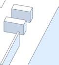


















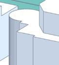


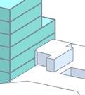




NY-MN-1867-9, NY-MN-1867-29, NY-MN-1867-30, NY-MN-1867-31, NY-MN-1867-33






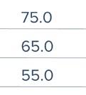
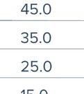


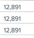




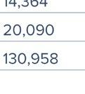


 ZONING ANALYSIS SCENARIO 1: As-Of-Right CF


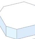









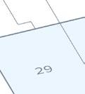






412












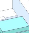

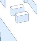



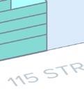
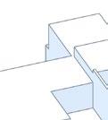


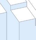


412
NY-MN-1867-29, NY-MN-1867-30, NY-MN-1867-31, NY-MN-1867-33












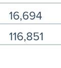


 ZONING ANALYSIS
SCENARIO 1A: CF As-Of-Right (w/o Clinic)

412


412
NY-MN-1867-9,


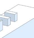






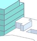


NY-MN-1867-9, NY-MN-1867-29, NY-MN-1867-30, NY-MN-1867-31, NY-MN-1867-33


 ZONING ANALYSIS SCENARIO 2: CF @ R8A


NY-MN-1867-9, NY-MN-1867-29, NY-MN-1867-30, NY-MN-1867-31, NY-MN-1867-33


 ZONING ANALYSIS SCENARIO 2: CF @ R8A





ZONING ANALYSIS SCENARIO 3: CF w/Lot 23 TDR
NY-MN-1867-9, NY-MN-1867-29, NY-MN-1867-30, NY-MN-1867-31, NY-MN-1867-33


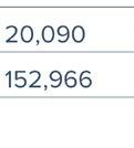


*Note prior transfer from Lot 9 diminishes the site's development




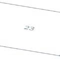

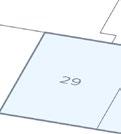











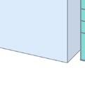
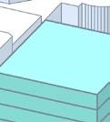



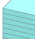










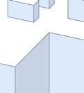


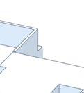




ZONING
METRICS (cont’d)










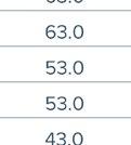


SCENARIO


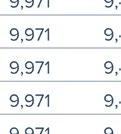


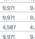
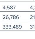


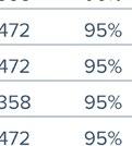
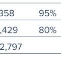


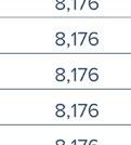


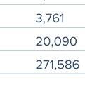



 3A: Tower w/TDR from Lots 23 &20

*Note


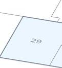







412








SCENARIO 3A: Tower w/TDR from Lots 23 &20
NY-MN-1867-9, NY-MN-1867-29, NY-MN-1867-30, NY-MN-1867-31, NY-MN-1867-33










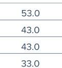












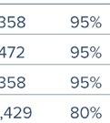



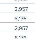


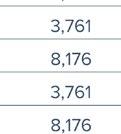
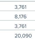


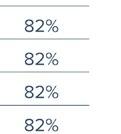


To: Carl Krebs, Fernando Hausch-Fen – Davis Brody Bond Architects
From: Jamie Rodger, P.E., Saul Shapiro, P.E.
Info: File
Date: 12 November 2021
Re: Preliminary Geotechnical Engineering Study
Columbia University Site 1 at Morningside Campus
410 West 115th Street, New York, NY
Langan Project No.: 170678401
This memorandum presents the results of our preliminary geotechnical investigation and provides preliminary geotechnical recommendations for the design and construction of the proposed Columbia University Site 1 development at the Morningside campus This report was prepared in general accordance with executed contract, dated 8 October 2021
Our understanding of the project requirements is based on our discussions with DBB and review of the concept architectural drawings dated 4 November 2021 and historic data provided, and our general experience in the area. The recommendations presented herein are in accordance with the 2014 New York City Building Code (NYCBC).
All elevations presented herein reference the North American Vertical Datum of 19881 (NAVD88). A topographic survey was not available at the time of this study; however, the existing ground surface was estimated using publically available LiDAR GIS digital mapping2 All elevations should be considered approximate and the elevations should be confirmed when a topographic survey is completed for the property
The “site” located at 410 West 115th Street in the Morningside section of Manhattan, New York. The property is comprised of four lots identified as Block 1867, Lots 29, 30, 31 , and 33 with a total footprint of about 16,685 square feet The site is bound to the north by West 115th Street, to the south by a 6-story residential building, a church, and a 3-story rectory building, to the east by a 6-story residential building, and to the west by a an 8-story building serving the Mount Sinai Morningside hospital campus. A site location plan is presented in Figure 1.
1 NAVD 88 is 1.1 feet above the USGS (NGVD 1929) mean sea level at Sandy Hook, NJ [NAVD = NGVD – 1.104] Elevations estimated from NYC 2017 LiDAR TopoBathymetric Bare Earth DEM (mosaic)
2 Elevations estimated from NYC 2017 LiDAR TopoBathymetric Bare Earth DEM (mosaic)
Preliminary Geotechnical Engineering Study
Columbia University Site 1 at Morningside Campus
410 West 115th Street, New York, NY
Langan Project No.: 170678401
12 November 2021- Page 2 of 10
The site is in the Morningside section of Manhattan and is used as an on-grade parking lot Historic aerial imagery shows the site was previously occupied by several buildings. The former building at the east side of the site (Lot 29) was demolished sometime between 1987 and 1995.
Three former buildings at the west side of the site (Lots 30, 31, and 33) were demolished around 2009. The historic demolition drawings provided show the foundation walls, footings, and basement floor slab to be removed. However, we do not know for certain if all of the foundation elements were removed. The former cellars of the three buildings were reported to be backfilled in October 2010 using compacted lifts of processed demolition debris and imported fill.
Surface grades within the parking lot are relatively flat and are estimated to vary from about el 128.5 ft to el 130 ft.
The southeast side of the site is bounded by the property of The Church of Notre Dame. The buildings on this property are identified as individual landmarks with the New York City Landmarks Preservation Commission (LPC). There appears to be a masonry retaining wall between the site and the church property and the difference in surface elevations between both properties is not known at this time The depth and extent of any below grade levels of the buildings bordering the site are also not known.
The proposed development is depicted on five different concept zoning scenarios prepared by Davis Brody Bond Architects dated 4 November 2021. Each concept considers various multi-story buildings ranging between 11-stories to 29-stories high. All concepts consider constructing a single cellar level to about 13-feet deep.
Some concepts extend beyond the limit of the site explored as part of this study. Additional investigation will be necessary if these other areas are considered for development. Preliminary structural foundation loads were not available at the time of this preliminary study
Local Geology
Geology in the site vicinity generally consists of gneiss and schist bedrock overlain by fill and glacial. According to Baskerville3, bedrock stratigraphy in the area consists of rock of the Lower Cambrian to Middle Ordovician Age (Hartland Formation). Below are generalized descriptions of rocks mapped in the vicinity of the site:
Hartland Formation – Interbedded units of (1) gray, fine-grained quartz-feldspar granulite containing minor biotite and garnet; (2) weathered fine- to coarse-grained, gray to tan quartz-feldspar-muscovite-biotite-garnet schist (mica schist); and (3) dark greenish-black quartz-biotite-hornblende amphibolite. Intrusions of granite and pegmatite are common
Preliminary Geotechnical Engineering Study
Columbia University Site 1 at Morningside Campus
410 West 115th Street, New York, NY
Langan Project No.: 170678401
12 November 2021- Page 3 of 10
(Baskerville 1994). Metamorphism has resulted in foliation – a distinct planar alignment of mineral grains – within rocks of the Hartland Formation. This grain alignment is commonly referred to as schistosity in the more platy schistose rock or compositional banding in gneissic rocks. Foliation is typically oriented either northwest or southeast and dips steeply within Manhattan as discussed by Baskerville, but may be altered locally as a result of folding.
An excerpt of the Baskerville bedrock geology map showing conditions in the site vicinity is presented in Figure 2.
Our preliminary geotechnical investigation included drilling three test borings identified as LB-1, LB-2(OW), and LB-3. Approximate locations of the borings are shown in Figure 3
Please note that additional investigation and analysis are required to provide final design information and to satisfy the NYCBC requirements for the minimum number of borings.
The borings were drilled by Craig Geotechnical Drilling, Co., Inc. between 25 October and 27 October 2021 using a truck-mounted drill rig under the full-time special inspection of Langan. The borings were advanced to depths of about 18 to 20 feet below the existing ground surface.
The borings were advanced through fill and soil using rotary drilling techniques with tri-cone roller bits and drilling fluid consisting of a mixture of polymer emulsion and water. Temporary flus h-joint steel casing was used to stabilize the boreholes and prevent fluid loss during drilling. The Standard Penetration Test (SPT)4 was performed in general accordance with ASTM D1586. Soils were sampled using a standard 2-inch-outer-diameter split-spoon sampler. SPT N-values and visual soil classifications were recorded by Langan’s inspecting engineer. All recovered soil samples were visually classified in the field in accordance with ASTM D2487 and the NYCBC.
Bedrock was cored using an NX-sized double-walled core barrel in general accordance with ASTM D2113. Recovery (REC)5 and rock quality designation (RQD)6 were determined for each core run. About 10 feet of bedrock was cored in all three boreholes
A 2-inch-diameter PVC groundwater observation well was installed in LB-2(OW) following completion of drilling. The well screen straddled the interface between decomposed rock and competent rock, and the well was flushed and pumped to establish the stabilized groundwater level.
Preliminary Geotechnical Engineering Study
Columbia University Site 1 at Morningside Campus
410 West 115th Street, New York, NY
Langan Project No.: 170678401
12 November 2021- Page 4 of 10
Soil and rock classifications, SPT N-values, REC, RQD, and other field observations were recorded on the boring logs, and well construction log, included in Appendix A.
The general subsurface stratigraphy observed within the borings consists of uncontrolled fil l underlain by a layer of soft (decomposed) rock, and by competent bedrock. Detailed descriptions of each subsurface stratum are given below in order of increasing depth.
Stratum 1 – Uncontrolled and Controlled Fill [Class 7] 7
Uncontrolled and controlled fill was observed in all borings. The controlled fill placement is described in the historic demolition documents. The fill generally consists of medium to fine sand with variable concentrations of silt, gravel, and construction debris (e.g., brick, concrete, wood, etc.). The fill layer is estimated to extend to depths of about 6 feet to 8 feet below existing ground surface. SPT N-values typically varied from 6 to practical refusal (i.e., more than 50 blows over six inches of penetration) and were typically less than 20 bpf (blow per foot); the higher recorded SPT N-values are likely attributed to the presence of decomposed rock and construction debris, and are generally not considered a representative indicator of in situ density. The fill layer is generally considered to be in a medium dense to dense condition.
The fill classifies as Class 7 “Uncontrolled and Controlled Fill” in accordance with the NYCBC.
Stratum 2 – Granular Soil [Class 3 a ]
Dense coarse sand with decomposed rock fragments was observed at LB-3 below Stratum 1. The granular soil of Stratum 2 generally consisted of brown to gray medium to fine sand with variable concentrations of silt, gravel, and decomposed rock
The top of the sand layer was encountered at about 6 feet below existing grade at LB-3, corresponding to about el 122 ft. SPT N-values varied from 44 to 66.
The soils of Stratum 2 is generally considered as dense to very dense and generally classifies as SP-SM (poorly graded sand - silty sand) or SM (silty sands and sand-silt mixtures) in accordance with USCS, and as Class 3a “Dense Granular Soils,” in accordance with the NYCBC.
Stratum 3 – Rock
Soft rock (i.e. NYCBC Class 1d) was encountered in LB-1 and LB-3. The soft rock was encountered above the competent rock and measured about 1-foot thick
Competent bedrock was encountered in all borings. The top of competent bedrock (i.e., NYCBC Class 1c or better) varied from about 8 to 10 feet below existing grade. The top of bedrock is defined as the depth where rock coring started
Preliminary Geotechnical Engineering Study
Columbia University Site 1 at Morningside Campus
410 West 115th Street, New York, NY
Langan Project No.: 170678401
12 November 2021- Page 5 of 10
The bedrock typically consists of mica schist comprised of muscovite, tourmaline, garnet, and sillimanite Weathering of the bedrock varied from slightly weathered to fresh and fracture spacing varied from very close to wide. The rock is generally of a competent nature with RQD values between 55 to 98 percent (NYCBC Class 1a and Class 1b).
The bedrock classifies as Class 1a “hard sound rock” and Class 1b “medium hard rock” in accordance with the NYCBC. Where present, the highly weathered/highly fractured rock classifies as Class 1d “soft rock” in accordance with the NYCBC.
Seismic design parameters were determined in accordance with the general procedures outlined in Section 1613.5 of the NYCBC. Foundations will consist of individual spread footings or strip footing that bear directly on bedrock or within 10 feet of rock. Therefore, we recommend that the site be assigned to Site Class B – “Rock”. The design spectral acceleration at short periods (SDS) is equal to 0.187g and the design spectral acceleration at 1-second (SD1) is equal to 0.049g. The resulting seismic design category ( SDC) is B. We assume that building will be assigned to Structural Occupancy/Risk Category III. This must be confirmed by the architect and structural engineer. Seismic design parameters are summarized are presented in Table 1
Liquefaction need not be considered for the design given that all soils are to be removed from the site and that the structure will be entirely supported on bedrock.
Preliminary Geotechnical Engineering Study
Columbia University Site 1 at Morningside Campus
410 West 115th Street, New York, NY
Langan Project No.: 170678401
12 November 2021- Page 6 of 10
The Federal Emergency Management Agency (FEMA) Primary Flood Insurance Rate Map (PFIRM), plate 3604970087G, and the effective Flood Insurance Rate Map (FIRM), plate 3604970087F bot show the site falls within unshaded portion of Zone X – Areas determined to be outside the 0.2% annual chance floodplain. Floodproofing is not required by the NYCBC or ASCE 24.
The following section summarizes our preliminary design and construction considerations associated with foundations and support of excavation for the proposed building:
The excavation to accommodate construction of a single cellar is anticipated to extend to depths of up to about 17 feet below existing grade; the corresponding subgrade elevation is about el 112 ft
The site seismic design category (SDC) is B. Liquefaction need not be considered in the design of the building.
Competent bedrock was encountered at depths varying from about 8 to 10 feet below grade. The majority of the rock is NYCBC Class 1a hard-sound rock and Class 1b mediumhard rock and can require significant effort to excavate.
Groundwater was observed to be perched atop rock at a depth of about 8 feet below grade. Significant dewatering during construction is not anticipated, but some dewatering will be required to drain the site initially and to address surface water accumulation following precipitation events
The design of foundation walls and cellar slabs must consider hydrostatic pressures, and foundation waterproofing must be installed to protect below grade space
The building on the southeast is a designated landmarked building and the provisions of TPPN10/88 must be followed. Construction adjacent to the landmark may also be subject to the review and approval of the LPC
The following sections present our preliminary recommendations for geotechnical design.
The subsurface conditions are considered amenable for supporting the proposed building using conventional shallow foundations comprised of continuous and isolated footings bearing atop competent bedrock Foundations should be proportioned assuming a gross allowable bearing pressure of 40 tons per square foot (tsf). The new foundation elements must bear at or below
Preliminary Geotechnical Engineering Study
Columbia University Site 1 at Morningside Campus
410 West 115th Street, New York, NY
Langan Project No.: 170678401
12 November 2021- Page 7 of 10
the footings of the adjacent buildings. Isolated footings should have a minimum plan dimension of 3 feet, and continuous strip footings should have a minimum width of 1.5 feet.
Settlement of the shallow foundations will be the result of elastic compression of the rock mass and is expected to be negligible. Estimated settlements are dependent on the footing size and structural loads, and should be reevaluated once these parameters are finalized.
Lateral loads can be resisted by friction on the bottom of footings or mat. We recommend an ultimate friction coefficient of 0.70 for mass concrete poured on clean sound rock and a minimum factor of safety of 1.5 when evaluating friction res istance. If additional resistance is needed, lateral loads can also be resisted by using shear pins doweled into rock, and/or by embedding footings to develop passive resistance from the surrounding rock. The allowable passive resistance provided by the rock will be dictated by the depth of embedment and the presence of discontinuities (fractures and foliation) at a particular location. Alternatively, floor slabs can be used as diaphragms to transfer loads to the exterior walls.
The groundwater level is judged to be perched atop of the soft rock and sound bedrock at about 8 feet below existing grade. We recommend that the design groundwater level be assumed at a height of two feet above the stabilized groundwater table, or about el 123 ft to account for a utility breaks and prolonged precipitation that increase the water table. The proposed lowest level slab is expected to be located below the design groundwater level.
We recommend that all slabs and walls be designed to resist the full hyd rostatic pressure resulting from a design groundwater level of el 123 ft. While foundation drains and under-slab drainage systems are considered technically feasible, recent amendments to the Rules of the City of New York (RCNY) governing the use of public sewers (Title 15 RCNY - Chapter 19) explicitly preclude permanent groundwater discharge to a NYC sewer. While historically implemented throughout NYC, use of such drainage systems could place the property owner at risk to penalties, as outlined in the Administrative Code of the City of New York (24-524).
The lowest floor slab should be designed as a pressure slab to resist the hydrostatic pressure resulting from the design groundwater at el 123 ft. The slab must be designed integral with the walls and the columns. Intermediate vertical anchors as discussed above may be added between the columns to optimize floor slab thickness. The pressure slabs should be keyed into the foundation walls and cast with integral water -stops to prevent possible seepage at cold joints. The pressure slab should also be waterproofed as per the recommendations presented herein.
Preliminary Geotechnical Engineering Study
Columbia University Site 1 at Morningside Campus
410 West 115th Street, New York, NY
Langan Project No.: 170678401
12 November 2021- Page 8 of 10
Uplift loads may be generated as a result of hydrostatic loads or from overturning forces caused by wind or seismic conditions Where present, uplift loads can be resisted using post-tensioned tie-down anchors. Post-tensioned tie-down anchors must consist of Class I (double corrosionprotected) high-strength threaded bars meeting ASTM A722.
The layout of the tie-down anchors must to be considered to provide the necessary uplift capacity and global stability (group effects), which is a function of the free-stressing length of the individual tie-down, and spacing of tie-downs.
We recommend waterproofing foundation walls and pits with a fully bonded membrane type waterproofing system such as those manufactured by GCP Applied Technologies (formerly Grace Construction Products), Carlisle Coatings and Waterproofing, or Sika. We also recommend using a waterproofing membrane beneath below grade floors. The selection of waterproofing membranes should be coordinated with any environmental design and regulatory requirements. We recommend against using bentonite waterproofing or post -applied negative side crystalline waterproofing as a primary means of groundwater control.
We recommend installing horizontally applied waterproofing membranes on a minimum 2 inch thick lean concrete mud slab placed over an approved subgrade to provide a smooth, uniform application surface. Vertically applied waterproofing membranes should extend up to grade. Substrate preparation should be as per the manufacturer’s recommendation.
Quality control is critical to a successful waterproofing project. The waterproofing installation should be inspected daily, especially during placement of reinforcement for the floor slabs and perimeter walls. Any holes or tears should be repaired by following the manufacturer’s recommendations. Utility penetrations should be carefully sealed. All seams, including separations between wall and slab membranes, should be checked for tightness. We recommend that the waterproofing manufacturer inspect the waterproofing operations during construction and approve all work before concrete is poured. We also suggest discussing waterproofing details with the selected manufacturer.
The above waterproofing system described above will only protect the foundations of the new development and will not provide any waterproofing protection to adjacent foundations. Furthermore, it is unknown whether the adjacent foundations were waterproofed and whether any such system(s) are still functional. Adjoining foundations which are exposed during excavation for the development must be waterproofed as required by Section 3309.3 of the NYCBC.
Preliminary Geotechnical Engineering Study
Columbia University Site 1 at Morningside Campus
410 West 115th Street, New York, NY
Langan Project No.: 170678401
12 November 2021- Page 9 of 10
Permanent below-grade walls will be subjected to lateral pressures from soil, rock, surcharge, and groundwater (hydrostatic) loads. Our preliminary lateral-pressure diagram is presented in Figure 4. We recommend that the below-grade wall next to the sidewalk be designed to resist a minimum vertical surcharge load of 300 psf. However, higher surcharge loads could be applied during construction from crane pads and outriggers; these loads (if applicable) will be provided by the crane designers. Earth pressures below the top of rock must be evaluated when the final foundation configuration is established and rock mass discontinuity data is available to appropriately estimate such loading For the purposes of preliminary design, we recommend a uniform lateral pressure of 250 psf be assumed within rock.
Construction of the foundation of the new building will require general site preparation, excavation of fill and rock, and subgrade preparation. Other associated activates may include underpinning and monitoring of adjacent buildings in accordance with Technical Policy and Procedure Notice (TPPN) #10/88 – Procedures for the Avoidance of Damage to Historic Structures Resulting from Adjacent Construction.
An important consideration related to building design is consideration of the volume and quality of rock excavation required to establish the proposed cellar depths We will provide detailed construction recommendations when the design is developed and we prepare our final geotechnical engineering study.
We recommend that Langan remain engaged to assist the design team in developing the construction documents pertaining to foundations and earthwork for the project. We expect that our involvement during design may include: 1) completing additional geotechnical investigation, including borehole geophysical logging and excavation of test pits, 2) preparation of technical specifications; 3) review of design documents prepared by others; and 4) development of earthwork schemes (including support of excavation and underpinning systems).
Preliminary Geotechnical Engineering Study
Columbia University Site 1 at Morningside Campus
410 West 115th Street, New York, NY
Langan Project No.: 170678401
12 November 2021- Page 10 of 10
The conclusions and recommendations provided in this preliminary report are based on subsurface conditions inferred from a limited number of borings, performed within the development parcel, and information provided by others. Additional exploration and analysis is required for design.
This report has been prepared to assist the owner, architect, and structural engineer in the preliminary design process and is only applicable to the envisioned project discussed herein. Any proposed changes in structures or their locations should be brought to our attention so that we can determine whether such changes affect our recommendations. Langan cannot assume responsibility for use of this preliminary report for any areas beyond the limits of this study or for any projects not specifically discussed herein. This report must not be used for the design of temporary works including scaffolding, construction hoists, and crane pads.
Information on subsurface strata and groundwater levels shown on the logs represents conditions encountered only at the locations indicated and at the time of investigation. If different conditions are encountered during construction, they should immediately be brought to Langan’s attention for evaluation because they may affect our recommendations.
Environmental issues (such as potentially contaminated soil and gr oundwater) are outside the scope of this study.
Sincerely,
Langan Engineering, Environmental, Surveying, Landscape Architecture, and Geology, D.P.C.

INITIAL: SS/jr
Enclosure(s):
Figure 1 – USGS Site Location Map
Figure 2 – Bedrock Geology Map
 Saul Shapiro, P.E. Principal
Figure 3 – Preliminary Subsurface Investigation Location Plan
Figure 4 – Preliminary Lateral Pressure Diagram
Appendix A – Preliminary Geotechnical Boring Logs

SOURCE:
NOTE:
SURCHARGE q (psf)
0.5q psf
WATER
ROCK
GROUND SURFACE EL. 129±
SOIL
60 psf 1 ft
DESIGN FLOOD EL.125.0±
63 psf 1 ft
29 psf 1 ft
MEASURED GWT EL.121.0±
LEGEND:
= HEIGHT OF BELOW GRADE WALL (FT)
H
= DEPTH TO DESIGN GROUND WATER TABLE (FT), (EL.123.0±)
H W
250 psf
H
ROCK VARIES (TBD)
WH GWTH RH
BELOW-GRADE WALL
NOTES:
= DEPTH TO MEASURED GROUND WATER TABLE (FT), (EL.121.0±)
H GWT
ROCK PRESSURES PROVIDED HEREIN ARE PRELIMINARY AND MUST BE REEVALUATED BASED ON APPLIED SURCHARGE LOAD AND BEDROCK DISCONTINUITY DATA.
1.
= HEIGHT OF ROCK (FT) MIN. SIDEWALK SURCHARGE = 300 PSF
H R
WARNING: IT IS A VIOLATION OF THE NYS EDUCATION LAW ARTICLE 145 FOR ANY PERSON, UNLESS HE IS ACTING UNDER THE DIRECTION OF A LICENSED PROFESSIONAL ENGINEER, LAND SURVEYOR OR GEOLOGIST, TO ALTER THIS ITEM IN ANY WAY.
Asphalt
Dark brown coarse-fine SAND, some brick, some m-f gravel, trace silt, concrete fragments (moist)[FILL](Class 7)
Dark gray coarse-fine SAND, some brick, some concrete, some m-f gravel, trace silt (moist)[FILL](Class 7)
Reddish brown coarse-fine SAND, some brick, some concrete, some silt, medium gravel fragments (wet)[FILL](Class 7)
Reddish brown medium-fine SAND, some brick, some silt, some medium gravel, trace concrete (wet)[FILL](Class 7)
Dark gray medium-fine SAND, trace brick, trace silt (wet)[DECOMPOSED ROCK](Class 1d)
Gray SCHIST; medium to coarse grained; muscovite-garnet-tourmaline-sillimanite; slightly weathered; very close to close fracture spacing; fractures shallow dipping to near horizontal; disturbed; rock quality fair; [BEDROCK]; (Class 1b)
Started Drilling at 10/27/2021 8:40 AM
Predrill 3in thick asphalt. Take S-1 from 0.5 to 2ft
Take S-2 from 2 to 4ft
Introduce drilling water. Drill to 4ft, smooth drilling with grayish brown return
Take S-3 from 4 to 6ft
Take S-4 from 6 to 8ft
Drill to 8ft, smooth drilling with brown return
Take S-5 from 8 to 10ft
Obstruction encountered at 9ft. Drive casing from 0 to 9ft. Drill to 10ft, light rig chattering with grayish brown return. Start coring at 10ft C-1 at 10ft
C-2 at 15ft
Gray SCHIST; medium to coarse grained; muscovite-garnet-tourmaline-sillimanite; fresh; moderate fracture spacing; fractures shallow dipping to near horizontal; intact; rock quality excellent; [BEDROCK]; (Class 1a)
End of Boring 20 ft
Bottom of boring at 10/27/2021 11:20 AM
Borehole backfilled with soil cuttings and patched with cold asphalt
Asphalt
Grayish brown coarse-fine SAND, some Silt, trace Brick, trace m-f Gravel, trace Wood (dry) [FILL] (Class 7)
Brown medium-fine SAND, some Silt, trace Brick, medium Gravel fragments (wet) [FILL] (Class 7)
Orangish brown coarse-fine SAND, some Brick, some Silt, some m-f Gravel (wet) [FILL] (Class 7)
Brown coarse-fine SAND, trace Brick, trace Silt, fine Gravel fragments (wet) [FILL] (Class 7)
Gray SCHIST; fine to medium grained muscovite-garnet-tourmaline-sillimanite; fresh; close to moderate fracture spacing; fractures moderately dipping to shallow dipping; rock quality good; [BEDROCK]; (Class 1b)
Started Drilling at 10/25/2021 1:20 PM
Predrill 3in thick asphalt
Take S-1 from 0 to 2 ft
Take S-2 from 2 to 4 ft
Introduce drilling water. Drill to 4ft, smooth drilling with brown return
Take S-3 from 4 to 6 ft
Take S-4 from 6 to 8 ft
Drive casing to 8ft. Drill to 8ft, smooth drilling with grayish brown return C-1 at 8ft
Gray SCHIST; fine to medium grained muscovite-garnet-tourmaline-sillimanite; fresh; wide fracture spacing; fractures moderately dipping; intact; rock quality excellent; [BEDROCK]; (Class 1a)
End of Boring
Bottom of boring at 10/25/2021 3:40 PM
Install a monitoring well. Refer to well construction log for details. Surface was patched with mixed cement
Asphalt
Grayish brown coarse-fine SAND, trace Brick, trace Silt, trace fine Gravel (dry) [FILL] (Class 7)
Grayish brown coarse-fine SAND, some Concrete, some m-f Gravel, trace Brick, trace Silt (wet) [FILL] (Class 7)
Grayish brown coarse-fine SAND, some Silt, trace Brick, trace fine Gravel (wet) [FILL] (Class 7)
Brown medium-fine SAND, some Silt, some Decomposed Rock, trace fine Gravel (wet) [SM] (Class 3a)
Brown to gray medium-fine SAND, some Decomposed Rock, trace Silt (wet) [SP-SM] (Class 3a)
Gray micaceous SCHIST; fine to medium grained muscovite-tourmaline-sillimanite; fresh; wide fracture spacing; fractures near horizontal; intact; rock quality excellent; [BEDROCK]; (Class 1a)
4 S-3SS80/5
Started Drilling at 10/25/2021 10:35 AM
Predrill 3in thick asphalt
Take S-1 from 0 to 2ft
Obstruction encountered at 1.25ft. Introduced drilling water, drill to 2ft, smooth drilling with brown return
Take S-2 from 2 to 4ft
Obstruction encountered at 3.5ft. Drill to 4ft, smooth drilling with brown return
Take S-3 from 4 to 6ft
Obstruction encountered at 4.5ft. Drill to 6ft, smooth drilling with brown return
Take S-4 from 6 to 8ft
Take S-5 from 8 to 10ft
Drive casing to 9ft. Switch to 4-7/8" roller bit and drill to 10ft, smooth to moderate rig chattering with brown return
Take S-6 from 10 to 12ft, obstruction encounrtered at 10ft. Switch to core barrel for rock coring C-1 at 10ft
C-2 at 15ft
Gray micaceous SCHIST; fine to medium grained muscovite-tourmaline-sillimanite; fresh to slightly weathered; moderate to wide fracture spacing; fractures shallow dipping to near horizontal; intact; rock quality excellent; [BEDROCK]; (Class 1a) End of Boring 20 ft
Bottom of boring at 10/25/2021 1:10 PM
Borehole backfilled with soil cuttings and bentonite to grade, top patched with cold asphalt
10/25/2021
Alex Tricanico
Rong Zhao
The boring was advanced to 18 feet below the existing ground surface using mud rotary drilling techniques and NX core barrel. The well was installed to 13 feet below the ground surface and consisted of 10 feet slotted PVC pipe (screen) and 3 feet solid PVC pipe (riser) at top. A flush-mount well cap was installed to seal the well.
The observation well was flushed clean and developed using a pump.

MORNING SIDE CAMPUS - SITE 1
COLUMBIA UNIVERSITY CONCEPT DESIGN NARRATIVE
JULY 11, 2022


As part of Columbia’s current sustainability initiatives, building systems for all new construction on campus will not be using fossil fuels. This building will be served by stand- alone systems and will not be connecting to campus systems due to the distance and cost of connection. The following sections detail the proposed systems to serve the building, as well as energy conservation measures to reduce overall energy consumption.
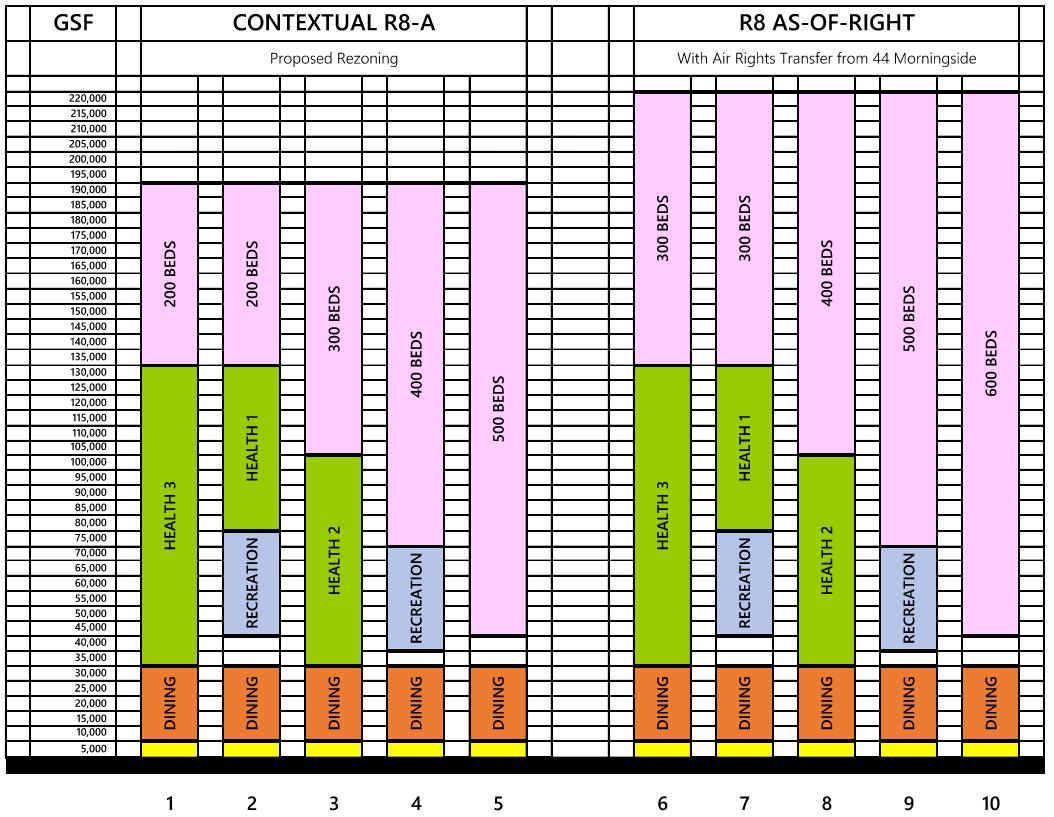

Using industry averages, and rough estimates of encl osure are as, it is predicted that t he high-performance envelope listed in the table above, will have a UA performance up to 35% better than NYS 2020 Stretch Code. Any value not explicit ly listed is expected to perform at prescriptive code values. The UA analysis below assumes a window-to-wall ratio of 30% for both baseline and proposed. Actual envelope performance will be determined as the design is developed fu rther.


Thermal bridge mitigation is an important part of envelope design High risk locations of thermal bridges are (1) Balconies/jewel boxes/overhangs (2) Corners/junctions (3) Windows Thermal bridge mitigation will be a part of 2023 NYS Stretch Code which will be adopted by NYC.


High performance buildings have a strong focus on reduced infiltration , tightly sealed, continuous air barriers, and well controlled moisture movement. We recommend working with architect to encourage these types of assembly systems to improve overall performance of the building’s enclosure.
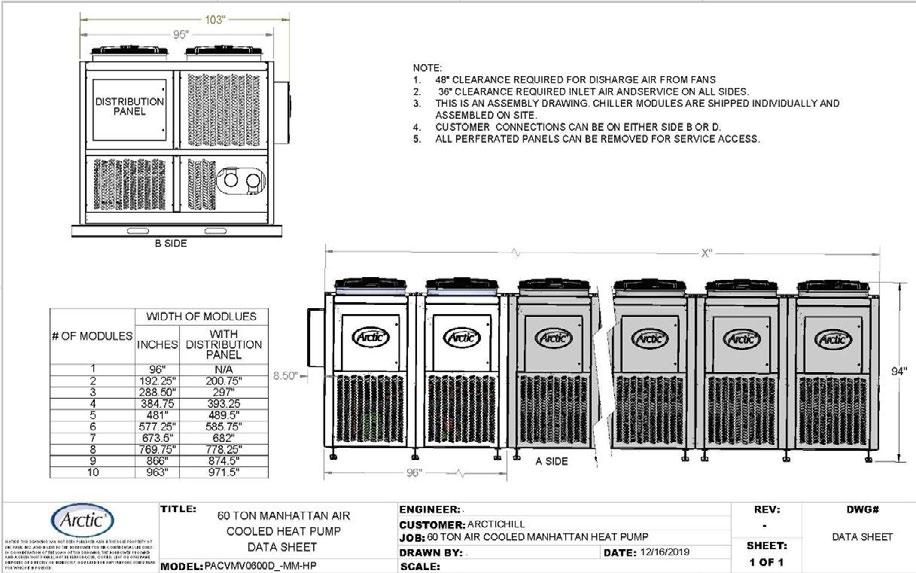

At 60-tons of cooling per module, the proposed design requires at least 5 modules. The dark blue section marked on in Figure 6 below represents the sizing of the ASHP. As seen in the cut sheet above, Figure 5, five (5) modules have overall dimensions of 103” x 489.5”. These dimensions do not include setback requirements on roof spaces. In Figure 6, the cyan blue area demarks the overall size of 2 400 -ton cooling towers. The dimension of this equipment is approximately 14’ x 28’, with a weight of 52,000 lbs. There will also be water source heat pump equipment located on the roof. It’s placement and total size is still being developed.

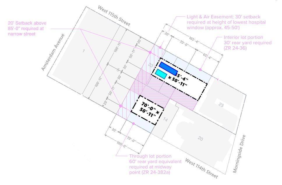


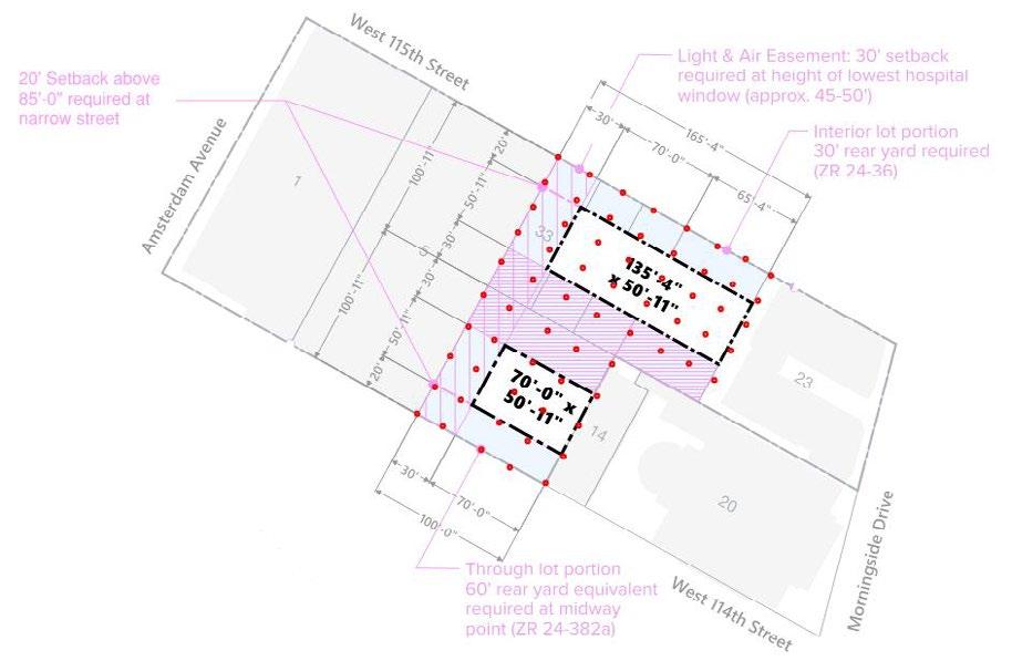
At 25 ft on center, the lot can fit approximately 40 wells. This does not include site boundary permitting limits and setbacks.
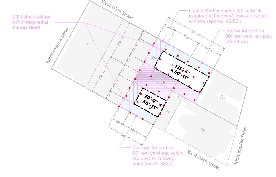

A significant amount of heat is generated in a commercial kitchen that can be recycled for use elsewhere in the building. Preliminary analysis of the commercial kitchen estimates 5 million BTUs of recovery heat available per day.
A significant portion of this heat can be captured from the kitchen hood exhaust. An exhaust air handling unit will be used to extract this heat from the exhaust air stream. As shown in Figure 10 this air handling unit will consist of an exhaust fan, energy recovery coil, specialized air filtration and air treatment, and a water source heat pump utilized to mechanically transfer this heat into the campus hot water loop.
This method involves coupling the air handling unit to a water source heat pump wher e the energy recovery coil serves as the evaporator and the water -cooled condenser serves the heating hot water system directly. This method allows for high levels of controllability and heat recovery. Additional analysis upon refinement of the commercial kitchen and kitchen design will provide further detail
The air treatment systems will prove be a key component of the kitchen exhaust air handling unit. As shown in Figure 10 it includes a combination of a pre -filter, electrostatic precipitation (basis of design: Trion), photo catalytic oxidation (basis of design: Genesis Air), and UV light treatment. These air treatment systems combined will ensure clean, odor -free, and environmentally friendly air exhausted to the surrounding campus atmosphere. It al so ensures grease and other effluent byproducts are removed from the air stream prior to entering the fan and energy recovery coil region of the air handling unit ; which ensure minimal maintenance requirements and overall longevity of the equipment.
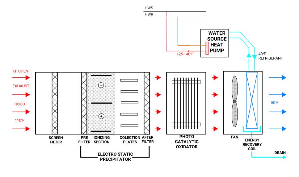

As seen in Figure 11, the electrostatic precipitator captures airborne effluent particles by passing the air through an electrostatic field. The particles receive an ionized charge and move through a collection stage containing same and opposite charged plates. Every other plate is positively charged, and the other set of every other plate is negatively charged. The plate that maintains the same charge as the ionized particles, drive these particles to the oppositely charged plates which serve as the particle collectors. These particle collectors can be washed and replaced back into the system. Additionally, unlike typical air filters where dirty filters increase pressure drop and decrease airflow in the system, as th e collectors become dir ty it only results in an airflow drop of less than 5%.

As seen in Figure 9 the photo catalytic oxidator removes particles responsible for poor air quality and odors. It does this by breaking down the molecular bonds of these particles; including VOCs. As shown in the diagram, the photo catalyst titanium dioxide produces hydroxyl radicals which break down the molecular structure of airborne particles. The resulting re-combination of the components result in formation of molecules not harmful or odiferous.


Coolers and freezers that support kitchen and commissary operations produce consistent, 24/7 heat recovery opportunities. A compressor rack refrigeration skid will be required to maintain the appropriate temperatures within each cooler and freezer. Instead of allowing the heat removed from the coolers and freezers (and its associated compressor motor heat) to be rejected to the atmosphere, a water -cooled condenser will be utilized to transfer this heat into the building hot water loop. The basis of design for this refr igeration skid is Zero Zone, Inc. (see Figure 14) with other competitors such as Hill Phoenix allowed to bid.
One key mechanism to accomplish effective heat transfer to the campus hot water loop is through specification of a refrigerant that optimizes t he cooler and freezer application and at the same time allows for heat to be transferred into the hot water loop. Modern technology has utilized carbon dioxide (CO2) as a refrigerant in applications such as this. CO2 is a natural refrigerant that is envi ronmentally benign, safe, and commonly used in refrigeration applications. CO2 has an ozone depletion potential of zero and a low global warming potential (GWP) of one (1). Upon further design of the commercial kitchen, CO2 and other refrigerants will be analyzed for this application to ensure a cost effective and energy efficient means of transferring this heat
Air handling units that feature large quantities of ventilation air in a single system will benefit from various forms of exhaust energy recovery. As each building matures in its design and load profile, more specifics on energy savings from heat recovery will be published. Dep ending on the application, energy recovery wheels often present the best cost/benefit analysis. A few options are presented below:
In this method, a single energy recovery wheel is positioned upstream of cooling and heating coils and tempers the outside air with energy from the building exhaust air. In AHU cooling mode, this results in decrease in both temperature and humidity in the resulting supply air. In AHU heating mode this results in an increase in both temperature a nd humidity. This method results in up to 90% energy recovery from the exhaust air but will be less based on the climate conditions; especially if defrost cycles are required. Thermotech is the basis of design due to its resilient construction, warranty, and 25-year


In this method, the same function is performed as the single energy recovery wheel method above with one of two wheels. However, a second wheel allows for humidity control during the summer, if desired. This wheel is place downstream of the cooling coil. The process is shown in the psychrometric chart below. This method not only provides humidity control but also obtains approximately 70 – 75% energy savings.


Heat reclamation system “power-pipe” will be installed on all drain piping from showers and bathtubs. “Power-pipe” is a vertical, counterflow heat exchanger that extracts heat out of drain water (usually warm) and applies it to preheat the cold water entering the building . The “Power-pipe” is installed into a section of available, vertical drain line in a dwelling. The design consists of a 2-inch central copper pipe (that carries the warm wastewater) with 1/2-in. copper coils wound around the central pipe. Heat is transferred from the wastewater passing through the large, central pipe to cold water simultaneously moving upward through the coils on the outside of the pipe. The coils are flattened a little where they touch the pipe to increase the contact area and imp rove heat transfer. The key to this patented device was that wastewater clings in a film-like fashion to the inside wall of the pipe as it undergoes gravity flow in the open drain, and this warm, falling film transfers heat through the pipe wall to the incoming cold water that passes through the copper coil wound around the pipe.

The Site 1 building will require local temperature boosting of the domestic hot water. The latest hot water heat pump technology replaces the need for a local boile r by means of an air source heat pump to produce hot water temperatures as high as 176°F and at the same time use carbon dioxide (CO2) as the refrigerant The basis of design will be the Mitsubishi QAHV.

In standard HVAC and refrigeration applications, CO2 typically operates at low condensing temperatures (70 – 90°F). Once the condensing temperature exceeds approximately 100°F and 1000 psi, the refrigerant enters a super -critical state wh ere phase change is no longer applicable toward heat exchange. Due to its patented heat exchanger technology, the QAHV efficiently operates in the super -critical region and allows for high leaving hot water temperatures of up to 176°F. The QAHV also contains an inverter equipped compressor to allow for variable speed operation in steps of 1706 Btu/hr. The design will accommodate a large temperature difference between the inlet and outlet temperature as this machine operates very efficiently at a high del ta T.
A single module has a published output of 136,480 Btu/hr with an outdoor ambient temperature between 36°F - 122°F. Modules can be cascaded together to up to 16 total modules. This air source heat pump can operate down to an outdoor ambient temperature of -13°F at approximately 47% the published Btu/hr output. The coefficient of performance of the QAHV exceeds that of a fuel burning boiler.
The QAHV shall be equipped with the system as shown in Figure 16. The indirect heat exchanger is used for domestic water applications and the storage tank is required to maintain stable operation. This heat pump cannot be used for space heating or similar applications.

RAINWATER RECOVERY
An average of 50+ inches of rainwater fall in New York city, per weather.gov (2010 -2019). The rainwater that falls on Site 1 can be harvested and used for cooling tower make up. We propose an AquaCell system.
SOLAR
Because roof space is limited, we recommend instillation of 2-axis tracking photovoltaic arrays to be installed on the roof to maximize efficacy of solar energy system. Paired with batteries, this energy could be used to power electric vehicle charging. Current basis of design is EOS Aqueous Zinc battery syst ems.

Per NYC Administrative Code 406.2.11 Electrical Vehicle Charging stations, 3.1 kW of electrical capacity must be provided to at least 20% of parking spaces of a parking garage. By January 1 2030, that 3.1 kW capacity must be provided to 40% of parking spaces. If there is to be parking available on the site, we will propose Level 2 chargers to meet this requirement.
Hogan Hall • Columbia University • 116 Beds
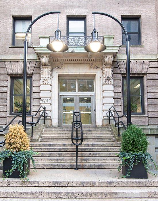
Completion 1898 (converted 1994; renovated 2000)
Size 51,300 GSF
116 beds, 442 GSF (per bed)
6 stories
Features Full suite — kitchen, bath, living
Hogan Hall • Columbia University • 116 Beds
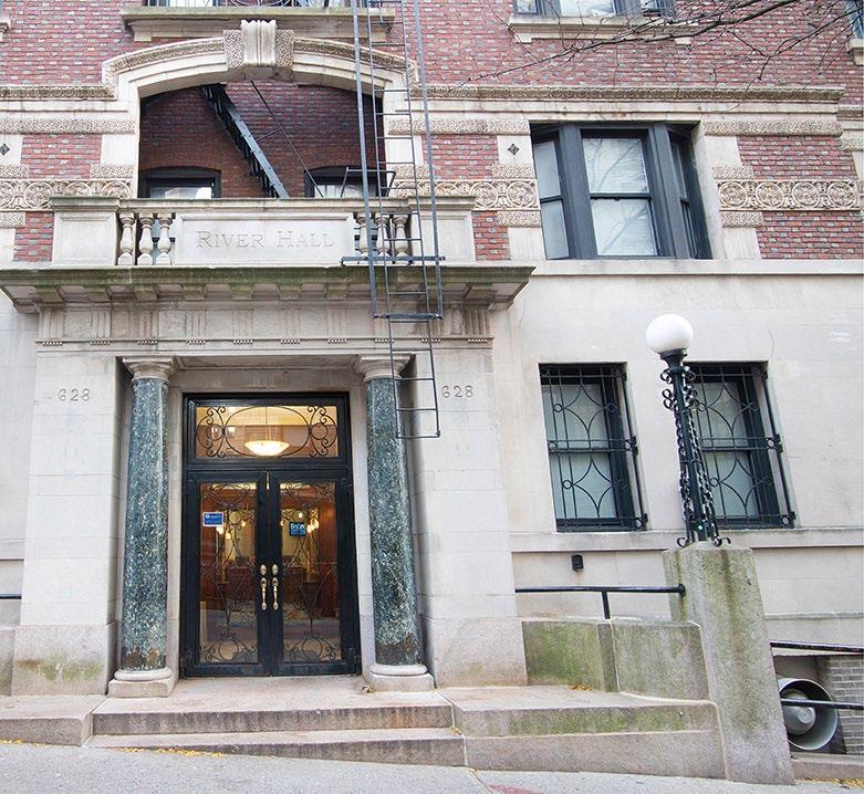
Completion 1906 (renovated 2001)
Size 32,100 GSF
129 beds, 241 GSF (per bed)
6 stories
Features Individual bedrooms accessible from shared corridors

Completion 2015
Architect Bohlin Cywinski Jackson
Size 198,000 GSF
344 beds, 576 GSF (per bed) 7 stories
Features Half suite; bath, living 3-6 beds per suite
Teaching kitchen; fitness rooms; meditation garden
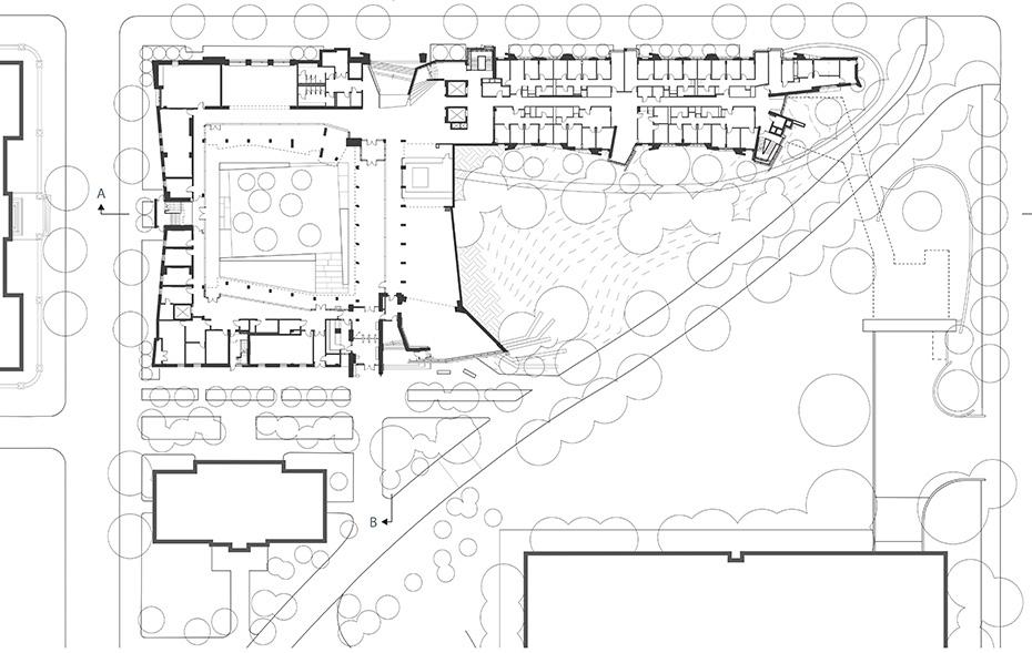
Completed 2022
Architect Bohlin Cywinski Jackson
Size 250,000 GSF
450 beds, 556 GSF (per bed) 98 suites
13-story center tower, (2) 5-story
Features Half suites; bath, living; Teaching kitchen; fitness rooms; meditation garden


Completion 2018
Architect Deborah Berke Partners
Size 41,950 GSF
129 beds, 325 GSF (per bed)
4 stories
Features Individual bedrooms accessible from shared corridors, organized into groups; mix of 1- and 2-bed units
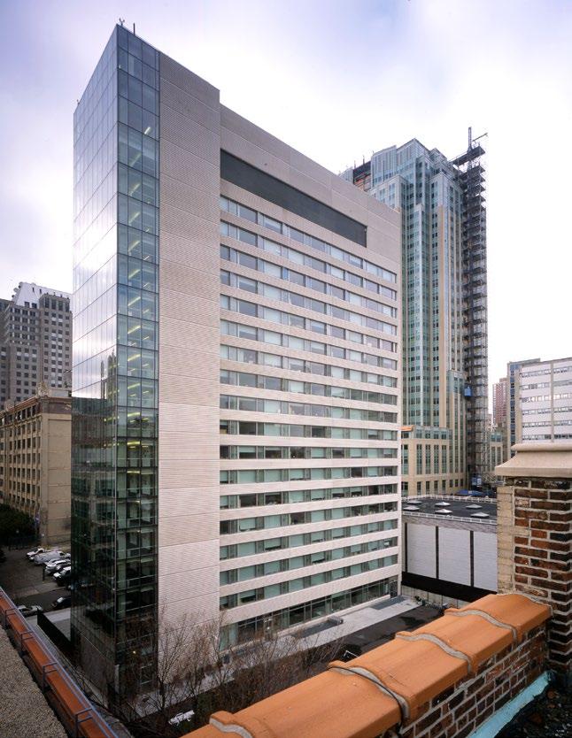
Completion 2002
Architect Davis Brody Bond
Size 200,000 GSF
400 beds, 500 GSF (per bed)
18 stories
Level 2-8 (112 units; no kitchen)
Level 9-18 (94 suites)
Features Full suite; Kitchen, Bath, Living
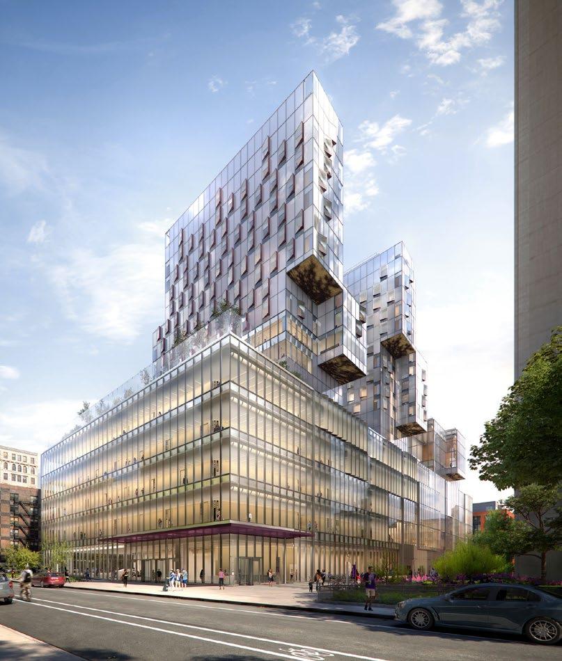
Completion 2023
Architect Davis Brody Bond / KieranTimberlake
Size 156,000 GSF
415 beds, 376 GSF (per bed)
16-story student tower
Features Student housing level 8-16 (114 units)
Half suite: bath, living
Comprised of 1-5 bedroom units
26'11"University Hall • New York University • 606 Beds
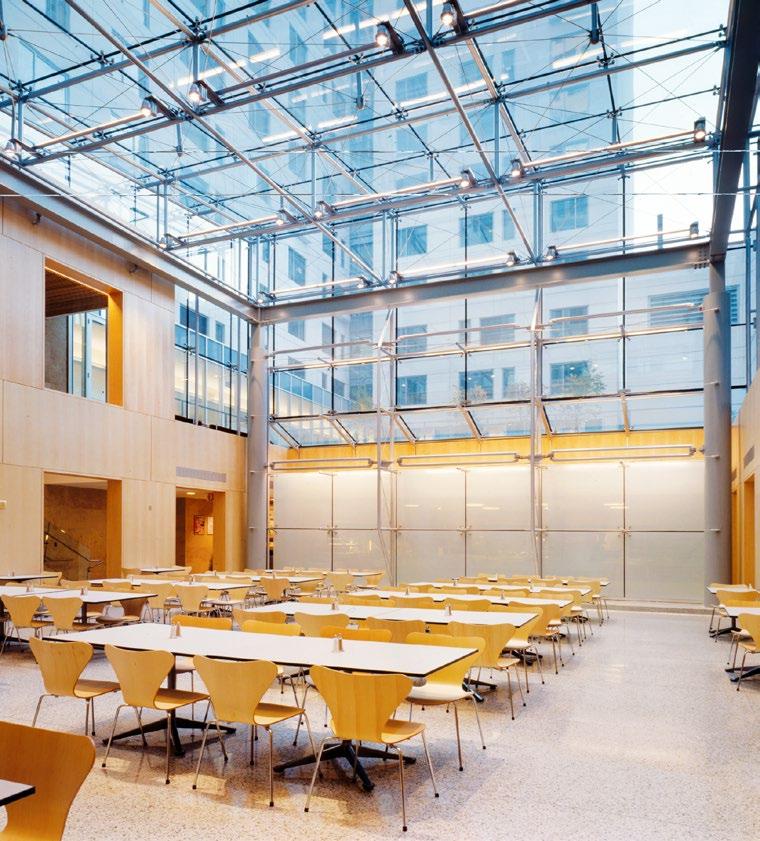
Completion 1998
Architect Davis Brody Bond
Size 200,000 GSF
606 beds, 330 GSF (per bed)
18 stories
Features Full suite; kitchen, bath, living
UNIT REFERENCE:
NYU UNIVERSITY HALL
APPROX. 758 GSF
APPROX. 573 NSF
FLOOR PLATE AREA: 10447 GSF
Completion 2021
Architect William Rawn Associates
Size 96,000 GSF
162 beds, 593 GSF (per bed), 4-5 stories
Features Shared bath & community spaces; individual bedrooms accessible from shared corridors; co-located with a student health & wellness center; includes flexible spaces for shared residential and health programming.
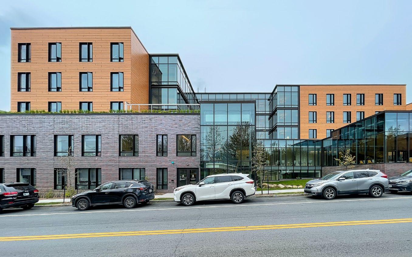

Completion 2023
Architect Deborah Berke and Partners
Size
125,000 GSF (64,000 + 61,000)
353 beds, 354 GSF (per bed)
5 stories
Features Half suites; bath, living
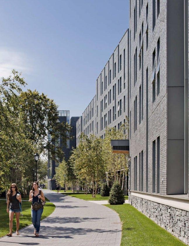
Completion 2010
Architect Sasaki
Size 170,000 GSF
460 beds, 370 GSF (per bed)
5 stories
Features Full suites; kitchen, bath, living

Completion 2016
Architect Studio Gang Architects
Size 394,000 GSF
800 beds, 493 GSF (per bed)
3 towers, 15, 11, & 5 floors
252 singles, 193 doubles
Features Grouped into (8) “houses” of (100) students
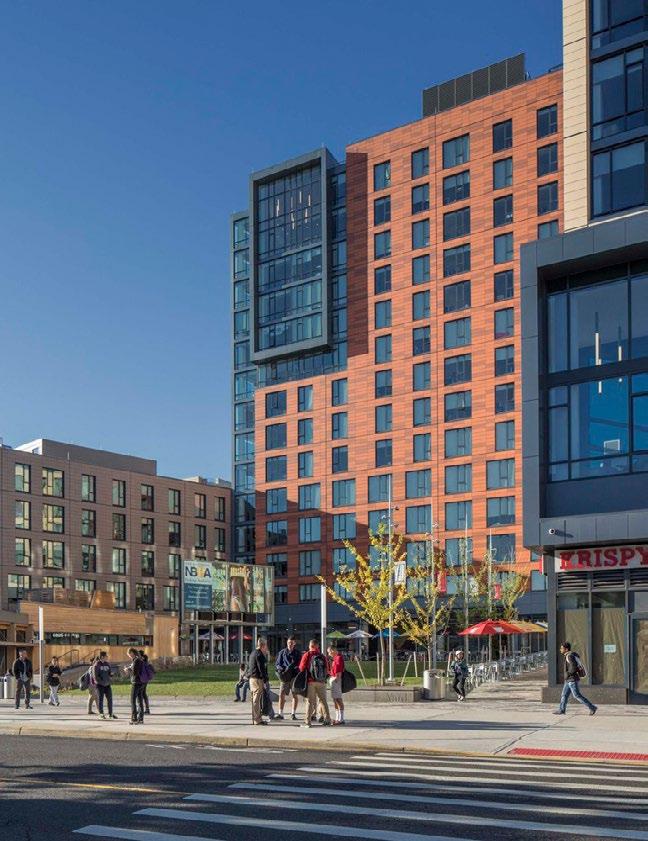
Completion 2016
Architect Elkus Manfredi Architects Size 232,000 GSF
422 beds, 550 GSF (per bed)
135 apartments
13 stories
Features Full suites; kitchen, bath, living


Completion 2017
Architect William Rawn Associates
Size 140,000 GSF
450 beds, 332 GSF (per bed)
7 stories, 4 stories (west side)
Features Half suites; bath, living (2, 4 bed suites)


Completion 2014
Architect SOM
Size 130,000 GSF residence tower
600 beds, 217 GSF (per bed)
16 stories, 9 residential
Features Full suite; kitchen, bath, closet
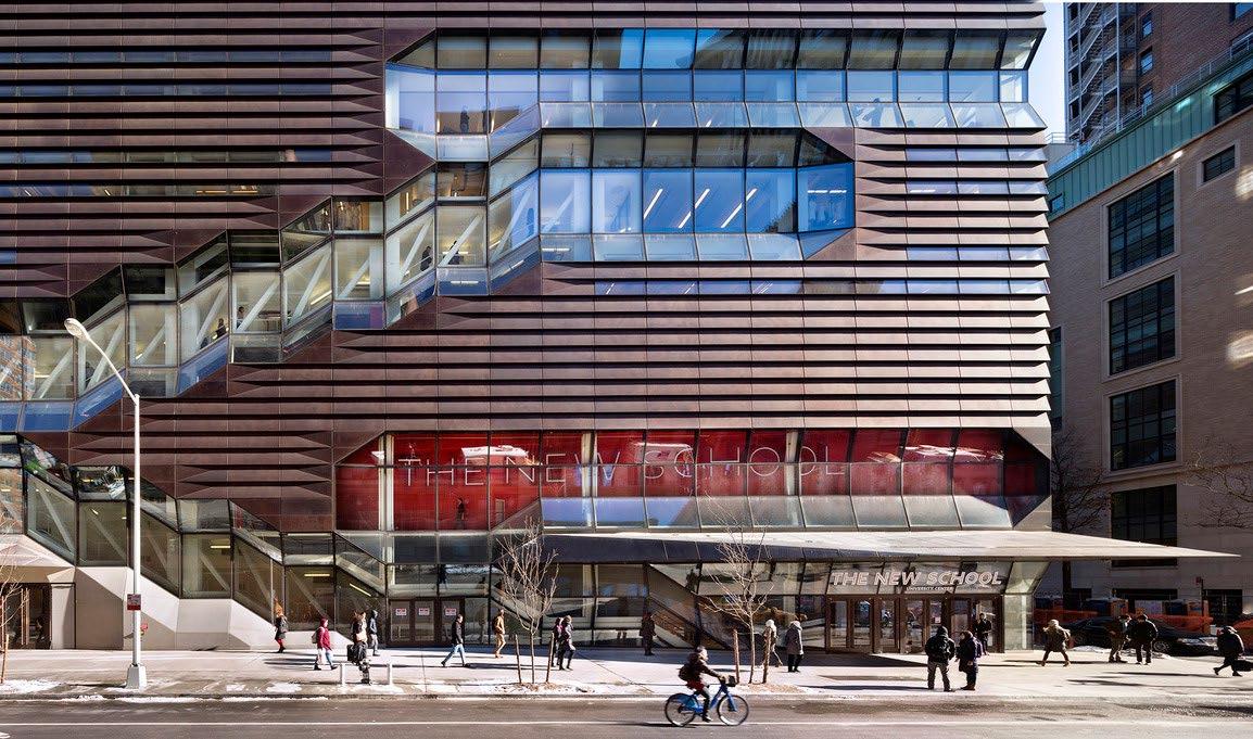
Accessible through shared common area or directly from street. Entrance from 115th Street is preferred.
Access will be more restrictive than other potential program in the building. Security control point should restrict access to students who live in the dormitory and their guests. Provide security desk, no office needed.
Mail and package delivery at Columbia University is centralized on campus for all undergraduate residents. A dedicated mail and package room is not required.
Overall dormitory size is flexible, however 200 beds is considered a minimum size to foster a sense of community. Note that programming below is based on a 9-story dormitory of 22-23 beds per floor.
Student rooms may be organized into suites, however direct access to bedrooms from the corridor is preferred. Enclosed suites with internal corridors and private common rooms are not encouraged.
to a specific group of
subtotal is
on a 9-story dormitory. Rooms for Resident Advisors should be provided at a ratio of 1 for every 40 students or 1 per floor if the number of students per floor is less than 40. Resident Advisors rooms can be a typical two-bed room, but should have a table and two chairs in lieu of the second bed. RAs do not need a dedicated bathroom and may share with other students on the floor
for this


HAND CRAFTED SOLUTIONS.
ELEVATED EXPERIENCES.


• Basis of Design
• Micro Restaurant Concepts
• Space Program ming
• Sizing Comparison
• Option 1 | Food Hall (Full Program)
• Option 2 | Food Hall (Reduced Program)
• Option 3 | Food Hall (Basic Program)


• Preference for attended service model with a focus on hospitality
• Incorporate Teaching Kitchen concept; used by culinary team with no classes
• Need area/process to handle orders for allergy/dietary meal restrictions
• No need for onsite scratch baking program with NYC retail bakeries readily available
• Catering not a priority at this dining commons


• This concept maximizes fresh preparation in an exhibition style format that utilizes small batch production, as well as foods prepared by the main kitchen staff. This approach enhances the customer’s perception of freshness and demystifies the origin of the product.
• In its purest sense the approach is to create mini restaurants or “platforms”. Each platform has its own food production and service format, but with an architecturally coordinated identity. With much of the food preparation and cooking done in front of the customer, preliminary and bulk preparation is supported by the main production kitchen.
• This exhibition servery will bring many of the kitchen functions out of the back of the house, thus visually engaging the customer in the process of preparing and serving food. This creates a dynamic, lively, and interactive environment bridging the areas of food production and product authenticity and customer service.
• Merchandising is another key component to this concept. The use of retail food display equipment as well as retail graphics and lighting will display food in an attractive manner and improve the perceived quality of the products offered.
• Control Points: access to the Commons all-you-care-to-eat(AYCE)dining program is an important factor during peak lunch and dinner times. Controlling the flow of customers into the space will allow the service points have time to adjust to peak customer surges and maintain consistent flow and customer throughput.
• Dining Areas: seating areas should incorporate a variety of table styles to include four-tops, communal tables, bar-height and counter height. Additional elements should include self-service beverage stations, condiment stations and trash/recycling disposal counters. Seating layouts should take into consideration late night service and study areas.
• Micro Restaurants: A collection of micro restaurants presented as defined concepts with individual identities and a strong point of view. Each micro restaurant will have the ability to expand and contract in menu and offering based on demand.
• Main Kitchen & Support: Designed to support Commons Food Hall concept. Requires easy access to the loading dock and freight elevators. Infrastructure includes refrigerated and dry storage, hot and cold production, trash and recycling, ware-washing, food service offices and staff facilities.


• Anchored by a wood-burning hearth oven, this platform can offer a variety of baked and roasted menu items.
• Hand-tossed Pizzas, Flatbreads, Pasta al Forno and Casseroles.


• A grill-powered restaurant with a core menu of breakfast and lunch offerings.
• Pop-up concepts to include popular fare and chef innovations.
• The go-to counter for the latest in NYC dining trends and local community engagement.


• Fresh sunny flavors from across the Mediterranean including Halal prepared proteins and authentic Middle-eastern fare.
• A tossed salad hub, similar to Sweet Greens or Chop’t, featuring Made-to-Order Salads and Grain Bowls celebrating the Mediterranean diet.
• Additional offerings could include a Levantine Hummus Bar, Spanish Tapas, or Southern French Dips and Bread Baskets.


• Farmer’s Market-forward offering of self-serve salad components, composed salads, hot and cold beans & grains & proteins.
• A rotating selection of seasonal hot comfort foods with a regional and global spin with a dedicated vegan and vegetarian section.
• Breakfast includes fruit, yogurt, breakfast salads, an avocado toast bar plus a variety of smears and toppings for baked goods.
• Soups and hot cereals complete a lunch or breakfast meal.


• Sandwiches, wraps and pressed paninis all prepared to order behind the scenes.
• Kiosk ordering.
• Guest pick-up from a designated “CLICK & COLLECT” pick-up window.


• Self-service hot and cold cereals to include nostalgic favorites such like Cap’n Crunch to organic granola, oldfashioned oatmeal and hominy grits.
• A Waffle Bar complete with toasters and waffle irons with an assortment of sweet and savory toppings to include everyone’s favorite, Southern Fried Chicken.


BEVERAGES
Tapped
• A custom beverage dispensing system with an array of sodas, iced tea, juice and sparkling beverages
Brewed
• Self-service dispensed drip coffee featuring local roasters and seasonal favorites
Packaged
• Located outside the control zone, a selection of packaged sandwiches, salads, sushi, nosh boxes and other on-the-go snacks


Columbia University - Site 1
Preliminary Room List
Campus Recreation
Student Wellbeing Center ( 36,500 GSF) perCampusRecreationUserMeetingOct27,2021and2019DodgeGymAreaProgram
Columbia University - Site 1
SCENARIO A1 FLOOR AREAS
LEVELGFAZFA %ZFA
Level 026777 SF00 SF
Level 126777 SF8021421 SF
Level 213982 SF9513283 SF
Level 313982 SF9513283 SF
Level 413982 SF9513283 SF
Level 511855 SF9511262 SF
Level 611855 SF9511262 SF
Level 711855 SF9511262 SF
Level 811855 SF9511262 SF
Level 96891 SF956546 SF
Level 106891 SF956546 SF
Level 116891 SF956546 SF
Level 126891 SF956546 SF
Level 136891 SF956546 SF
Level 146891 SF956546 SF
Level 156891 SF956546 SF
Level 166891 SF956546 SF
Level 176891 SF956546 SF
Level 186891 SF956546 SF 211827 SF171781 SF
SCENARIO A1 PROGRAM AREAS
SCENARIO A1 CELLAR
LEVELGFA USE
Level 02000 SFCOMMON
Level 015777 SFDINING
Level 09000 SFRESIDENTIAL (600 BEDS)
26777 SF
SCENARIO A1 GROUND FLOOR
LEVELGFA USE
Level 13000 SFCOMMON
Level 110000 SFDINING
Level 113777 SFRESIDENTIAL (600 BEDS)
26777 SF
USE TARGETSCENARIO
COMMON 5000 SF 5000 SF
DINING 26580 SF 25777 SF
RESIDENTIAL (600 BEDS)180000 SF 181050 SF
211827 SF
SCENARIO
LEVELGFA ZFA % ZFA
Level 026777 SF0 0 SF
Level 126777 SF8021421 SF
Level 215510 SF9514734 SF
Level 3N8418 SF957997 SF
Level 3S7092 SF956737 SF
Level 4N8418 SF957997 SF
Level 4S4964 SF954716 SF
Level 5N6891 SF956546 SF
Level 5S4964 SF954716 SF
Level 6N6891 SF956546 SF
Level 6S4964 SF954716 SF
Level 7N6891 SF956546 SF
Level 7S4964 SF954716 SF
Level 8N6891 SF956546 SF
Level 9N6891 SF956546 SF
Level 10N6891 SF956546 SF
Level 11N6891 SF956546 SF
Level 12N6891 SF956546 SF
Level 13N6891 SF956546 SF
Level 14N6891 SF956546 SF
Level 15N6891 SF956546 SF
Level 16N6891 SF956546 SF
Level 17N6891 SF956546 SF
Level 18N6891 SF956546 SF
Level 19N6891 SF956546 SF 216209 SF175944 SF
SCENARIO
SCENARIO A2 CELLAR
LEVELGFAZFAUSE
Level 02000 SF0 SFCOMMON
Level 015777 SF0 SFDINING
Level 09000 SF0 SFRESIDENTIAL
26777 SF0 SF
SCENARIO A2 GROUND FLOOR
LEVELGFAZFAUSE
Level 13000 SF2400 SFCOMMON
Level 113777 SF11021 SFRECREATION
Level 110000 SF8000 SFDINING 26777 SF21421 SF
SCENARIO A1 NORTH TOWER
LEVELGFA ZFA % ZFA USE
Level 26891 SF956546 SFRESIDENTIAL (600 BEDS)
Level 36891 SF956546 SFRESIDENTIAL (600 BEDS)
Level 46891 SF956546 SFRESIDENTIAL (600 BEDS)
Level 56891 SF956546 SFRESIDENTIAL (600 BEDS)
Level 66891 SF956546 SFRESIDENTIAL (600 BEDS)
Level 76891 SF956546 SFRESIDENTIAL (600 BEDS)
Level 86891 SF956546 SFRESIDENTIAL (600 BEDS)
Level 96891 SF956546 SFRESIDENTIAL (600 BEDS)
Level 106891 SF956546 SFRESIDENTIAL (600 BEDS)
Level 116891 SF956546 SFRESIDENTIAL (600 BEDS)
Level 126891 SF956546 SFRESIDENTIAL (600 BEDS)
Level 136891 SF956546 SFRESIDENTIAL (600 BEDS)
Level 146891 SF956546 SFRESIDENTIAL (600 BEDS)
Level 156891 SF956546 SFRESIDENTIAL (600 BEDS)
Level 166891 SF956546 SFRESIDENTIAL (600 BEDS)
Level 176891 SF956546 SFRESIDENTIAL (600 BEDS)
Level 186891 SF956546 SFRESIDENTIAL (600 BEDS) 117142 SF111285 SF
SCENARIO A1 SOUTH TOWER
LEVELGFA ZFA % ZFA USE
Level 27092 SF956737 SFRESIDENTIAL (600 BEDS)
Level 37092 SF956737 SFRESIDENTIAL (600 BEDS)
Level 47092 SF956737 SFRESIDENTIAL (600 BEDS)
Level 54964 SF954716 SFRESIDENTIAL (600 BEDS)
Level 64964 SF954716 SFRESIDENTIAL (600 BEDS)
Level 74964 SF954716 SFRESIDENTIAL (600 BEDS)
Level 84964 SF954716 SFRESIDENTIAL (600 BEDS) 41132 SF39075 SF
A.1 A.2
SCENARIO A2 NORTH TOWER
LEVELGFAZFAUSE
Level 28418 SF7997 SFRESIDENTIAL
Level 3N8418 SF7997 SFRESIDENTIAL
Level 4N8418 SF7997 SFRESIDENTIAL
Level 5N6891 SF6546 SFRESIDENTIAL
Level 6N6891 SF6546 SFRESIDENTIAL
Level 7N6891 SF6546 SFRESIDENTIAL
Level 8N6891 SF6546 SFRESIDENTIAL
Level 9N6891 SF6546 SFRESIDENTIAL
Level 10N6891 SF6546 SFRESIDENTIAL
Level 11N6891 SF6546 SFRESIDENTIAL
Level 12N6891 SF6546 SFRESIDENTIAL
Level 13N6891 SF6546 SFRESIDENTIAL
Level 14N6891 SF6546 SFRESIDENTIAL
Level 15N6891 SF6546 SFRESIDENTIAL
Level 16N6891 SF6546 SFRESIDENTIAL
Level 17N6891 SF6546 SFRESIDENTIAL
Level 18N6891 SF6546 SFRESIDENTIAL
Level 19N6891 SF6546 SFRESIDENTIAL 128615 SF122185 SF
SCENARIO A2 SOUTH TOWER
LEVELGFAZFAUSE
Level 27092 SF6737 SFRECREATION
Level 3S7092 SF6737 SFRECREATION
Level 4S4964 SF4716 SFRESIDENTIAL
Level 5S4964 SF4716 SFRESIDENTIAL
Level 6S4964 SF4716 SFRESIDENTIAL
SCENARIO A3 FLOOR AREAS
LEVELGFA ZFA
% ZFA
Level 026777 SF00 SF
Level 126777 SF8021421 SF
Level 215510 SF9514734 SF
Level 3N8418 SF957997 SF
Level 3S7092 SF956737 SF
Level 4N8418 SF957997 SF
Level 4S4964 SF954716 SF
Level 5N6891 SF956546 SF
Level 5S4964 SF954716 SF
Level 6N6891 SF956546 SF
Level 6S4964 SF954716 SF
Level 7N6891 SF956546 SF
Level 7S3564 SF953386 SF
Level 8N6891 SF956546 SF
Level 8S3564 SF953386 SF
Level 9N6891 SF956546 SF
Level 9S3564 SF953386 SF
Level 10N6891 SF956546 SF
Level 10S3564 SF953386 SF
Level 11N6891 SF956546 SF
Level 11S3564 SF953386 SF
Level 12N6891 SF956546 SF
Level 12S3564 SF953386 SF
Level 13N6891 SF956546 SF
Level 13S3564 SF953386 SF
Level 14N6891 SF956546 SF
Level 15N6891 SF956546 SF
Level 16N6891 SF956546 SF 215521 SF175291 SF
SCENARIO A3 PROGRAM AREAS
USEGFAZFA
COMMON5000 SF2400 SF
DINING25777 SF8000 SF
HEALTH65301 SF56745 SF
RESIDENTIAL119444 SF108146 SF
215521 SF175291 SF
SCENARIO A4 FLOOR AREAS
LEVELGFA ZFA % ZFA
Level 026777 SF00 SF
Level 126777 SF8021421 SF
Level 215510 SF9514734 SF
Level 3N8418 SF957997 SF
Level 3S7092 SF956737 SF
Level 4N6891 SF956546 SF
Level 4S4964 SF954716 SF
Level 5N6891 SF956546 SF
Level 5S4964 SF954716 SF
Level 6N6891 SF956546 SF
Level 6S4964 SF954716 SF
Level 7N6891 SF956546 SF
Level 7S3564 SF953386 SF
Level 8N6891 SF956546 SF
Level 8S3564 SF953386 SF
Level 9N6891 SF956546 SF
Level 9S3564 SF953386 SF
Level 10N6891 SF956546 SF
Level 10S3564 SF953386 SF
Level 11N6891 SF956546 SF
Level 11S3564 SF953386 SF
Level 12N6891 SF956546 SF
Level 13N6891 SF956546 SF
Level 14N6891 SF956546 SF
Level 15N6891 SF956546 SF
Level 16N6891 SF956546 SF
Level 17N6891 SF956546 SF 213756 SF173614 SF
SCENARIO A4 PROGRAM AREAS
GFAZFA USE
5000 SF2400 SFCOMMON
25777 SF8000 SFDINING
58173 SF49973 SFHEALTH
23727 SF22541 SFRECREATION
101079 SF90700 SFRESIDENTIAL
213756 SF173614 SF
SCENARIO A3 CELLAR
LEVELGFAZFAUSE
Level 02000 SF0 SFCOMMON
Level 015777 SF0 SFDINING
Level 04500 SF0 SFHEALTH
Level 04500 SF0 SFRESIDENTIAL
26777 SF0 SF
SCENARIO A3 GROUND FLOOR
LEVELGFAZFAUSE
Level 13000 SF2400 SFCOMMON
Level 110000 SF8000 SFDINING
Level 16776 SF5421 SFHEALTH
Level 17000 SF5600 SFRESIDENTIAL
26777 SF21421 SF
SCENARIO A4 CELLAR
LEVELGFAZFAUSE
Level 02000 SF0 SFCOMMON
Level 015777 SF0 SFDINING
Level 04500 SF0 SFHEALTH
Level 04500 SF0 SFRESIDENTIAL
26777 SF0 SF
SCENARIO A4 GROUND FLOOR
LEVELGFAZFAUSE
Level 13000 SF2400 SFCOMMON
Level 16776 SF5421 SFHEALTH
Level 110000 SF8000 SFDINING
Level 17000 SF5600 SFRESIDENTIAL
26777 SF21421 SF
SCENARIO A3 NORTH TOWER
LEVELGFA ZFA % ZFAUSE
Level 28418 SF957997 SFRESIDENTIAL
Level 3N8418 SF957997 SFRESIDENTIAL
Level 4N8418 SF957997 SFRESIDENTIAL
Level 5N6891 SF956546 SFRESIDENTIAL
Level 6N6891 SF956546 SFRESIDENTIAL
Level 7N6891 SF956546 SFRESIDENTIAL
Level 8N6891 SF956546 SFRESIDENTIAL
Level 9N6891 SF956546 SFRESIDENTIAL
Level 10N6891 SF956546 SFRESIDENTIAL
Level 11N6891 SF956546 SFRESIDENTIAL
Level 12N6891 SF956546 SFRESIDENTIAL
Level 13N6891 SF956546 SFRESIDENTIAL
Level 14N6891 SF956546 SFRESIDENTIAL
Level 15N6891 SF956546 SFRESIDENTIAL
Level 16N6891 SF956546 SFRESIDENTIAL 107943 SF102546 SF
SCENARIO A3 SOUTH TOWER
LEVELGFA ZFA % ZFAUSE
Level 27092 SF956737 SFHEALTH
Level 3S7092 SF956737 SFHEALTH
Level 4S4964 SF954716 SFHEALTH
Level 5S4964 SF954716 SFHEALTH
Level 6S4964 SF954716 SFHEALTH
Level 7S3564 SF953386 SFHEALTH
Level 8S3564 SF953386 SFHEALTH
Level 9S3564 SF953386 SFHEALTH
Level 10S3564 SF953386 SFHEALTH
Level 11S3564 SF953386 SFHEALTH
Level 12S3564 SF953386 SFHEALTH
Level 13S3564 SF953386 SFHEALTH 54025 SF51324 SF
A.3 A.4
SCENARIO A4 NORTH TOWER
LEVELGFAZFAUSE
Level 28418 SF7997 SFRECREATION
Level 3N8418 SF7997 SFRECREATION
Level 4N6891 SF6546 SFRECREATION
Level 5N6891 SF6546 SFRESIDENTIAL
Level 6N6891 SF6546 SFRESIDENTIAL
Level 7N6891 SF6546 SFRESIDENTIAL
Level 8N6891 SF6546 SFRESIDENTIAL
Level 9N6891 SF6546 SFRESIDENTIAL
Level 10N6891 SF6546 SFRESIDENTIAL
Level 11N6891 SF6546 SFRESIDENTIAL
Level 12N6891 SF6546 SFRESIDENTIAL
Level 13N6891 SF6546 SFRESIDENTIAL
Level 14N6891 SF6546 SFRESIDENTIAL
Level 15N6891 SF6546 SFRESIDENTIAL
Level 16N6891 SF6546 SFRESIDENTIAL
Level 17N6891 SF6546 SFRESIDENTIAL 113307 SF107641 SF
SCENARIO A4 SOUTH TOWER
LEVELGFAZFAUSE
Level 27092 SF6737 SFHEALTH
Level 3S7092 SF6737 SFHEALTH
Level 4S4964 SF4716 SFHEALTH
Level 5S4964 SF4716 SFHEALTH
Level 6S4964 SF4716 SFHEALTH
Level 7S3564 SF3386 SFHEALTH
Level 8S3564 SF3386 SFHEALTH
Level 9S3564 SF3386 SFHEALTH
Level 10S3564 SF3386 SFHEALTH
SCENARIO A5 FLOOR AREAS
LEVELGFA ZFA
% ZFA
Level 026777 SF00 SF
Level 126777 SF8021421 SF
Level 216689 SF9515855 SF
Level 3N9597 SF959118 SF
Level 3S7092 SF956737 SF
Level 4N9597 SF959118 SF
Level 4S7092 SF956737 SF
Level 5N9597 SF959118 SF
Level 5S4964 SF954716 SF
Level 6N9597 SF959118 SF
Level 6S4964 SF954716 SF
Level 7N6891 SF956546 SF
Level 7S4964 SF954716 SF
Level 8N6891 SF956546 SF
Level 8S4964 SF954716 SF
Level 9N6891 SF956546 SF
Level 9S3564 SF953386 SF
Level 10N6891 SF956546 SF
Level 10S3564 SF953386 SF
Level 11N6891 SF956546 SF
Level 11S3564 SF953386 SF
Level 12N6891 SF956546 SF
Level 12S3564 SF953386 SF
Level 13N6891 SF956546 SF
Level 13S3564 SF953386 SF
Level 14S3564 SF953386 SF
Level 15S3564 SF953386 SF 215856 SF175609 SF
SCENARIO A5 PROGRAM AREAS
GFAZFAUSE
5000 SF2400 SFCOMMON
25777 SF8000 SFDINING
107498 SF96832 SFHEALTH
77581 SF68377 SFRESIDENTIAL
215856 SF175609 SF
SCENARIO B1 FLOOR AREAS
LEVELGFAZFA %ZFA
Level 026777 SF00 SF
Level 126777 SF8021421 SF
Level 213006 SF9512356 SF
Level 38510 SF958085 SF
Level 48510 SF958085 SF
Level 58510 SF958085 SF
Level 68510 SF958085 SF
Level 78510 SF958085 SF
Level 88510 SF958085 SF
Level 98510 SF958085 SF
Level 108510 SF958085 SF
Level 118510 SF958085 SF
Level 128510 SF958085 SF
Level 138510 SF958085 SF
Level 148510 SF958085 SF
Level 158510 SF958085 SF
Level 168510 SF958085 SF
Level 178510 SF958085 SF
Level 188510 SF958085 SF
Level 198510 SF958085 SF
211229 SF171214 SF
SCENARIO B1 PROGRAM AREAS
USEGFAZFA
COMMON5000 SF2400 SF
DINING 25777 SF8000 SF
RESIDENTIAL180453 SF160814 SF
211229 SF171214 SF
SCENARIO A5 CELLAR
LEVELGFA ZFA % ZFAUSE
Level 02000 SF00 SFCOMMON
Level 015777 SF00 SFDINING
Level 04500 SF00 SFHEALTH
Level 04500 SF00 SFRESIDENTIAL
26777 SF0 SF
SCENARIO A5 GROUND FLOOR
LEVELGFA ZFA % ZFAUSE
Level 13000 SF802400 SFCOMMON
Level 110000 SF808000 SFDINING
Level 17000 SF805600 SFRESIDENTIAL
Level 16776 SF805421 SFHEALTH
26777 SF21421 SF
SCENARIO A5 NORTH TOWER
LEVELGFA ZFA % ZFAUSE
Level 29597 SF959118 SFHEALTH
Level 3N9597 SF959118 SFHEALTH
Level 4N9597 SF959118 SFHEALTH
Level 5N9597 SF959118 SFHEALTH
Level 6N9597 SF959118 SFHEALTH
Level 7N6891 SF956546 SFHEALTH
Level 8N6891 SF956546 SFHEALTH
Level 9N6891 SF956546 SFHEALTH
Level 10N6891 SF956546 SFHEALTH
Level 11N6891 SF956546 SFHEALTH
Level 12N6891 SF956546 SFHEALTH
Level 13N6891 SF956546 SFHEALTH 96222 SF91411 SF
SCENARIO A5 SOUTH TOWER
LEVELGFA ZFA % ZFAUSE
Level 27092 SF956737 SFRESIDENTIAL
Level 3S7092 SF956737 SFRESIDENTIAL
Level 4S7092 SF956737 SFRESIDENTIAL
Level 5S4964 SF954716 SFRESIDENTIAL
Level 6S4964 SF954716 SFRESIDENTIAL
Level 7S4964 SF954716 SFRESIDENTIAL
Level 8S4964 SF954716 SFRESIDENTIAL
Level 9S3564 SF953386 SFRESIDENTIAL
Level 10S3564 SF953386 SFRESIDENTIAL
Level 11S3564 SF953386 SFRESIDENTIAL
Level 12S3564 SF953386 SFRESIDENTIAL
Level 13S3564 SF953386 SFRESIDENTIAL
Level 14S3564 SF953386 SFRESIDENTIAL
Level 15S3564 SF953386 SFRESIDENTIAL 66081 SF62777 SF
A.5 B.1
SCENARIO B1 CELLAR
LEVELGFAZFAUSE
Level 02000 SF0 SFCOMMON
Level 015777 SF0 SFDINING
Level 09000 SF0 SFRESIDENTIAL 26777 SF0 SF
SCENARIO B1 GROUND FLOOR
LEVELGFAZFAUSE
Level 13000 SF2400 SFCOMMON
Level 110000 SF8000 SFDINING
Level 113777 SF11021 SFRESIDENTIAL 26777 SF21421 SF
SCENARIO B1 TOWER
LEVELGFAZFA %ZFAUSE
Level 213006 SF9512356 SFRESIDENTIAL
Level 38510 SF958085 SFRESIDENTIAL
Level 48510 SF958085 SFRESIDENTIAL
Level 58510 SF958085 SFRESIDENTIAL
Level 68510 SF958085 SFRESIDENTIAL
Level 78510 SF958085 SFRESIDENTIAL
Level 88510 SF958085 SFRESIDENTIAL
Level 98510 SF958085 SFRESIDENTIAL
Level 108510 SF958085 SFRESIDENTIAL
Level 118510 SF958085 SFRESIDENTIAL
Level 128510 SF958085 SFRESIDENTIAL
Level 138510 SF958085 SFRESIDENTIAL
Level 148510 SF958085 SFRESIDENTIAL
Level 158510 SF958085 SFRESIDENTIAL
Level 168510 SF958085 SFRESIDENTIAL
Level 178510 SF958085 SFRESIDENTIAL
Level 188510 SF958085 SFRESIDENTIAL
SCENARIO B2 FLOOR AREAS
LEVELGFA ZFA % ZFA
Level 026777 SF00 SF
Level 126777 SF8021421 SF
Level 213107 SF9512451 SF
Level 313107 SF9512451 SF
Level 48510 SF958085 SF
Level 58510 SF958085 SF
Level 68510 SF958085 SF
Level 78510 SF958085 SF
Level 88510 SF958085 SF
Level 98510 SF958085 SF
Level 108510 SF958085 SF
Level 118510 SF958085 SF
Level 128510 SF958085 SF
Level 138510 SF958085 SF
Level 148510 SF958085 SF
Level 158510 SF958085 SF
Level 168510 SF958085 SF
Level 178510 SF958085 SF
Level 188510 SF958085 SF
Level 198510 SF958085 SF 215926 SF175676 SF
SCENARIO B2 PROGRAM AREAS
GFAZFA USE
5000 SF2400 SFCOMMON
25777 SF8000 SFDINING
26883 SF23473 SFRECREATION
158267 SF141803 SFRESIDENTIAL 215926 SF175676 SF
SCENARIO B3 FLOOR AREAS
LEVELGFAZFA %ZFA
Level 026777 SF0 0 SF
Level 126777 SF8021421 SF
Level 214962 SF9514214 SF
Level 314962 SF9514214 SF
Level 414962 SF9514214 SF
Level 513107 SF9512451 SF
Level 68510 SF958085 SF
Level 78510 SF958085 SF
Level 88510 SF958085 SF
Level 98510 SF958085 SF
Level 108510 SF958085 SF
Level 118510 SF958085 SF
Level 128510 SF958085 SF
Level 138510 SF958085 SF
Level 148510 SF958085 SF
Level 158510 SF958085 SF
Level 168510 SF958085 SF
SCENARIO B2 CELLAR
LEVELGFA ZFA % ZFAUSE
Level 02000 SF00 SFCOMMON
Level 015777 SF00 SFDINING
Level 09000 SF00 SFRESIDENTIAL
26777 SF 0 SF
SCENARIO B2 GROUND FLOOR
LEVELGFA ZFA % ZFAUSE
Level 13000 SF802400 SFCOMMON
Level 113777 SF8011021 SFRECREATION
Level 110000 SF808000 SFDINING
26777 SF 21421 SF
SCENARIO B2 TOWER
LEVELGFA ZFA % ZFAUSE
Level 213107 SF9512451 SFRECREATION
Level 313107 SF9512451 SFRESIDENTIAL
Level 48510 SF958085 SFRESIDENTIAL
Level 58510 SF958085 SFRESIDENTIAL
Level 68510 SF958085 SFRESIDENTIAL
Level 78510 SF958085 SFRESIDENTIAL
Level 88510 SF958085 SFRESIDENTIAL
Level 98510 SF958085 SFRESIDENTIAL
Level 108510 SF958085 SFRESIDENTIAL
Level 118510 SF958085 SFRESIDENTIAL
Level 128510 SF958085 SFRESIDENTIAL
Level 138510 SF958085 SFRESIDENTIAL
Level 148510 SF958085 SFRESIDENTIAL
Level 158510 SF958085 SFRESIDENTIAL
Level 168510 SF958085 SFRESIDENTIAL
Level 178510 SF958085 SFRESIDENTIAL
Level 188510 SF958085 SFRESIDENTIAL
Level 198510 SF958085 SFRESIDENTIAL 162373 SF154255 SF
SCENARIO B3 CELLAR
LEVELGFAZFA %ZFAUSE
Level 02000 SF00 SFCOMMON
Level 04500 SF00 SFHEALTH
Level 015777 SF00 SFDINING
Level 04500 SF00 SFRESIDENTIAL 26777 SF0 SF
SCENARIO B3 GROUND FLOOR
LEVELGFAZFA %ZFAUSE
Level 13000 SF802400 SFCOMMON
Level 110000 SF808000 SFDINING
Level 17000 SF805600 SFRESIDENTIAL
Level 16776 SF805421 SFHEALTH 26777 SF21421 SF
SCENARIO B3 PROGRAM AREAS GFAZFAUSE
5000 SF2400 SFCOMMON 25777 SF8000 SFDINING
56161 SF48062 SFHEALTH
126727 SF115065 SFRESIDENTIAL 213665 SF173527 SF
B.2 B.3
SCENARIO B3 TOWER
LEVELGFAZFA %ZFAUSE
Level 214962 SF9514214 SFHEALTH
Level 314962 SF9514214 SFHEALTH
Level 414962 SF9514214 SFHEALTH
Level 513107 SF9512451 SFRESIDENTIAL
Level 68510 SF958085 SFRESIDENTIAL
Level 78510 SF958085 SFRESIDENTIAL
Level 88510 SF958085 SFRESIDENTIAL
Level 98510 SF958085 SFRESIDENTIAL
Level 108510 SF958085 SFRESIDENTIAL
Level 118510 SF958085 SFRESIDENTIAL
Level 128510 SF958085 SFRESIDENTIAL
Level 138510 SF958085 SFRESIDENTIAL
Level 148510 SF958085 SFRESIDENTIAL
Level 158510 SF958085 SFRESIDENTIAL
Level 168510 SF958085 SFRESIDENTIAL
Level 178510 SF958085 SFRESIDENTIAL 160112 SF 152106 SF
SCENARIO B4 FLOOR AREAS
LEVELGFA ZFA % ZFA
Level 026777 SF00 SF
Level 126777 SF8021421 SF
Level 213107 SF9512451 SF
Level 313107 SF9512451 SF
Level 413107 SF9512451 SF
Level 513107 SF9512451 SF
Level 613107 SF9512451 SF
Level 78510 SF958085 SF
Level 88510 SF958085 SF
Level 98510 SF958085 SF
Level 108510 SF958085 SF
Level 118510 SF958085 SF
Level 128510 SF958085 SF
Level 138510 SF958085 SF
Level 148510 SF958085 SF
Level 158510 SF958085 SF
Level 168510 SF958085 SF
Level 178510 SF958085 SF 212696 SF 172607 SF
SCENARIO B4 PROGRAM AREAS
GFA ZFA USE
5000 SF2400 SFCOMMON
25777 SF8000 SFDINING
56927 SF49805 SFHEALTH
26883 SF23473 SFRECREATION
98110 SF88930 SFRESIDENTIAL
212696 SF172607 SF
SCENARIO B5 FLOOR AREAS
LEVELGFA ZFA % ZFA
Level 026777 SF0 0 SF
Level 126777 SF8021421 SF
Level 217362 SF9516494 SF
Level 317362 SF9516494 SF
Level 417362 SF9516494 SF
Level 513107 SF9512451 SF
Level 613107 SF9512451 SF
Level 78510 SF958085 SF
Level 88510 SF958085 SF
Level 98510 SF958085 SF
Level 108510 SF958085 SF
Level 118510 SF958085 SF
Level 128510 SF958085 SF
Level 138510 SF958085 SF
Level 148510 SF958085 SF
Level 158510 SF958085 SF
Level 168510 SF958085 SF 216951 SF176650 SF
SCENARIO B5 PROGRAM AREAS
GFAZFA USE 5000 SF2400 SFCOMMON
SF8000 SFDINING
SF79804 SFHEALTH
SF86445 SFRESIDENTIAL
SF176650 SF
SCENARIO B4 CELLAR
LEVELGFA ZFA % ZFAUSE
Level 02000 SF00 SFCOMMON
Level 015777 SF00 SFDINING
Level 04500 SF00 SFHEALTH
Level 04500 SF00 SFRESIDENTIAL 26777 SF 0 SF
SCENARIO B4 GROUND FLOOR
LEVELGFA ZFA % ZFAUSE
Level 113777 SF8011021 SFRECREATION
Level 13000 SF802400 SFCOMMON
Level 110000 SF808000 SFDINING
26777 SF 21421 SF
SCENARIO B5 CELLAR
LEVELGFA ZFA % ZFAUSE
Level 02000 SF00 SFCOMMON
Level 015777 SF00 SFDINING
Level 04500 SF00 SFHEALTH
Level 04500 SF00 SFRESIDENTIAL 26777 SF 0 SF
SCENARIO B5 GROUND FLOOR
LEVELGFA ZFA % ZFAUSE
Level 13000 SF802400 SFCOMMON
Level 110000 SF808000 SFDINING
Level 17000 SF805600 SFRESIDENTIAL
Level 16776 SF805421 SFHEALTH 26777
Level
Level
Level
Level
Level
Level
Level
Level
SCENARIO B4 TOWER
LEVELGFA ZFA % ZFAUSE
Level 213107 SF9512451 SFRECREATION
Level 313107 SF9512451 SFHEALTH
Level 413107 SF9512451 SFHEALTH
Level 513107 SF9512451 SFHEALTH
Level 613107 SF9512451 SFHEALTH
Level 78510 SF958085 SFRESIDENTIAL
Level 88510 SF958085 SFRESIDENTIAL
Level 98510 SF958085 SFRESIDENTIAL
Level 108510 SF958085 SFRESIDENTIAL
Level 118510 SF958085 SFRESIDENTIAL
Level 128510 SF958085 SFRESIDENTIAL
Level 138510 SF958085 SFRESIDENTIAL
Level 148510 SF958085 SFRESIDENTIAL
Level 158510 SF958085 SFRESIDENTIAL
Level 168510 SF958085 SFRESIDENTIAL
Level 178510 SF958085 SFRESIDENTIAL 159143 SF151186 SF
B.5
SCENARIO C6 FLOOR AREAS
LEVELGFA ZFA % ZFA
Level 026777 SF00 SF
Level 126027 SF8020821 SF
Level 217734 SF9516848 SF
Level 3N10134 SF959628 SF
Level 3S7600 SF957220 SF
Level 4N10134 SF959628 SF
Level 4S7600 SF957220 SF
Level 5N8609 SF958179 SF
Level 5S5320 SF955054 SF
Level 6N8609 SF958179 SF
Level 6S5320 SF955054 SF
Level 7N6879 SF956535 SF
Level 7S5320 SF955054 SF
Level 8N6879 SF956535 SF
Level 8S5320 SF955054 SF
Level 9N6879 SF956535 SF
Level 9S5320 SF955054 SF
Level 10N6879 SF956535 SF
Level 10S4270 SF954057 SF
Level 11N6879 SF956535 SF 188493 SF149726 SF
SCENARIO C6 PROGRAM AREAS
GFAZFAUSE
5000 SF2400 SFCOMMON
25777 SF8000 SFDINING
157716 SF139326 SFRESIDENTIAL
188493 SF149726 SF
SCENARIO C7 FLOOR
LEVELGFA ZFA % ZFA
Level 026777 SF00 SF
Level 126777 SF8021421 SF
Level 218817 SF9517876 SF
Level 3N11725 SF9511139 SF
Level 3S7092 SF956737 SF
Level 4N11725 SF9511139 SF
Level 4S4964 SF954716 SF
Level 5N9597 SF959118 SF
Level 5S4964 SF954716 SF
Level 6N9597 SF959118 SF
Level 6S4964 SF954716 SF
Level 7N7567 SF957189 SF
Level 7S4964 SF954716 SF
Level 8N7567 SF957189 SF
Level 8S3914 SF953718 SF
Level 9N7567 SF957189 SF
Level 9S3914 SF953718 SF
Level 10N7567 SF957189 SF
SCENARIO C6 CELLAR
LEVELGFA ZFA % ZFAUSE
Level 02000 SF00 SFCOMMON
Level 015777 SF00 SFDINING
Level 09000 SF00 SFRESIDENTIAL
26777 SF0 SF
SCENARIO C6 GROUND FLOOR
LEVELGFA ZFA % ZFAUSE
Level 13000 SF802400 SFCOMMON
Level 110000 SF808000 SFDINING
Level 113026 SF8010421 SFRESIDENTIAL
26027 SF20821 SF
SCENARIO C6 NORTH TOWER
LEVELGFA ZFA % ZFAUSE
Level 210134 SF959628 SFRESIDENTIAL
Level 3N10134 SF959628 SFRESIDENTIAL
Level 4N10134 SF959628 SFRESIDENTIAL
Level 5N8609 SF958179 SFRESIDENTIAL
Level 6N8609 SF958179 SFRESIDENTIAL
Level 7N6879 SF956535 SFRESIDENTIAL
Level 8N6879 SF956535 SFRESIDENTIAL
Level 9N6879 SF956535 SFRESIDENTIAL
Level 10N6879 SF956535 SFRESIDENTIAL
Level 11N6879 SF956535 SFRESIDENTIAL 82019 SF77918 SF
SCENARIO C6 SOUTH TOWER
LEVELGFA ZFA % ZFAUSE
Level 27600 SF957220 SFRESIDENTIAL
Level 3S7600 SF957220 SFRESIDENTIAL
Level 4S7600 SF957220 SFRESIDENTIAL
Level 5S5320 SF955054 SFRESIDENTIAL
Level 6S5320 SF955054 SFRESIDENTIAL
Level 7S5320 SF955054 SFRESIDENTIAL
Level 8S5320 SF955054 SFRESIDENTIAL
Level 9S5320 SF955054 SFRESIDENTIAL
Level 10S4270 SF954057 SFRESIDENTIAL 53670 SF50987 SF
C.6
SCENARIO C7 CELLAR
LEVELGFAZFA %ZFAUSE
Level 02000 SF00 SFCOMMON
Level 015777 SF00 SFDINING
Level 09000 SF00 SFRESIDENTIAL
26777 SF0 SF
SCENARIO C7 GROUND FLOOR
LEVELGFAZFA %ZFAUSE
Level 13000 SF802400 SFCOMMON
Level 113777 SF8011021 SFRECREATION
Level 110000 SF808000 SFDINING 26777 SF21421 SF
SCENARIO C7 NORTH TOWER
C.7
LEVELGFAZFA %ZFAUSE
Level 211725 SF9511139 SFRESIDENTIAL
Level 3N11725 SF9511139 SFRESIDENTIAL
Level 4N11725 SF9511139 SFRESIDENTIAL
Level 5N9597 SF959118 SFRESIDENTIAL
Level 6N9597 SF959118 SFRESIDENTIAL
Level 7N7567 SF957189 SFRESIDENTIAL
Level 8N7567 SF957189 SFRESIDENTIAL
Level 9N7567 SF957189 SFRESIDENTIAL
Level 10N7567 SF957189 SFRESIDENTIAL
Level 11N7567 SF957189 SFRESIDENTIAL 92206 SF87596 SF
SCENARIO C7 SOUTH TOWER
LEVELGFAZFA %ZFAUSE
Level 27092 SF956737 SFRECREATION
Level 3S7092 SF956737 SFRECREATION
Level 4S4964 SF954716 SFRESIDENTIAL
Level 5S4964 SF954716 SFRESIDENTIAL
Level 6S4964 SF954716 SFRESIDENTIAL
Level 7S4964 SF954716 SFRESIDENTIAL
Level 8S3914 SF953718 SFRESIDENTIAL
Level 9S3914 SF953718 SFRESIDENTIAL 41868 SF39775 SF
SCENARIO C8 FLOOR AREAS
LEVELGFAZFA %ZFA
Level 026777 SF00 SF
Level 126777 SF8021421 SF
Level 218817 SF9517876 SF
Level 3N11725 SF9511139 SF
Level 3S7092 SF956737 SF
Level 4N11725 SF9511139 SF
Level 4S4964 SF954716 SF
Level 5N9597 SF959118 SF
Level 5S4964 SF954716 SF
Level 6N9597 SF959118 SF
Level 6S4964 SF954716 SF
Level 7N7567 SF957189 SF
Level 7S4964 SF954716 SF
Level 8N7567 SF957189 SF
Level 8S3914 SF953718 SF
Level 9N7567 SF957189 SF
Level 9S3914 SF953718 SF
Level 10N7567 SF957189 SF
Level 11N7567 SF957189 SF 187628 SF148792 SF
SCENARIO C8 PROGRAM AREAS
GFAZFAUSE
5000 SF2400 SFCOMMON
25777 SF8000 SFDINING
53145 SF45196 SFHEALTH
103706 SF93196 SFRESIDENTIAL
187628 SF148792 SF
SCENARIO C8 GROUND FLOOR
LEVELGFA ZFA % ZFAUSE
Level 13000 SF802400 SFCOMMON
Level 110000 SF808000 SFDINING
Level 16776 SF805421 SFHEALTH
Level 17000 SF805600 SFRESIDENTIAL
26777 SF21421 SF
SCENARIO C8 CELLAR
LEVELGFA ZFA % ZFAUSE
Level 02000 SF00 SFCOMMON
Level 015777 SF00 SFDINING
Level 04500 SF00 SFHEALTH
Level 04500 SF00 SFRESIDENTIAL
26777 SF0 SF
SCENARIO C8 NORTH TOWER
LEVELGFA ZFA % ZFAUSE
Level 211725 SF9511139 SFRESIDENTIAL
Level 3N11725 SF9511139 SFRESIDENTIAL
Level 4N11725 SF9511139 SFRESIDENTIAL
Level 5N9597 SF959118 SFRESIDENTIAL
Level 6N9597 SF959118 SFRESIDENTIAL
Level 7N7567 SF957189 SFRESIDENTIAL
Level 8N7567 SF957189 SFRESIDENTIAL
Level 9N7567 SF957189 SFRESIDENTIAL
Level 10N7567 SF957189 SFRESIDENTIAL
Level 11N7567 SF957189 SFRESIDENTIAL 92206 SF87596 SF
SCENARIO C8 SOUTH TOWER
LEVELGFA ZFA % ZFAUSE
Level 27092 SF956737 SFHEALTH
Level 3S7092 SF956737 SFHEALTH
Level 4S4964 SF954716 SFHEALTH
Level 5S4964 SF954716 SFHEALTH
Level 6S4964 SF954716 SFHEALTH
Level 7S4964 SF954716 SFHEALTH
Level 8S3914 SF953718 SFHEALTH
Level 9S3914 SF953718 SFHEALTH 41868 SF39775 SF
Clinical Pod
Clinical Pod (+/- 5,250 GSF)
Triage/Exam
Exam - Provider (6)
Exam - Reproductive Health (2)
Exam - Nursing (2)
Visiting + Adjunct Provider Exam
Tele - Medicine
Treatment Room
Vitals
Observation
Rest and Recovery
Dedicated toilet for R&R
Patient Toilet
Phlebotomy
Sub-Waiting
Patient Toilet
Nurses Station
Collaboration Room
Equipment Alcove - Crash Cart
Med Station
Microscope Room
Clean Supply
Equipment
Soiled Holding Room
Clinical Pod


North Bar
11,715 GSF/ Floor
Right Sized: 43,300 GSF, 3.75 Floors
2030: 58,400 GSF, 5 Floors
North Bar
6,890 GSF/ Floor
Right Sized: 22,620 GSF, 3.25 Floors
2030: 27,350 GSF, 4 Floors
North Bar
6,890 GSF/ Floor
Right Sized: 21,350 GSF, 3 Floors
2030: 22,160 GSF, 3.25 Floors
15,000 GSF/ Floor
Right Sized: 43,300 GSF, 3 Floors
2030: 58,400 GSF, 4 Floors
R8 - Single 40% Tower
Single Bar
13,100 GSF/ Floor
Right Sized: 22,620 GSF, 1.75 Floors
2030: 27,350 GSF, 2 Floors
Single Bar
10,600 GSF/ Floor
Right Sized: 21,350 GSF, 2 Floors
2030: 22,160 GSF, 2 Floors

