WHAT NECB BUILDING CODE CHANGES MEAN FOR ALBERTA
Understanding new roofing standards in the age of climate change
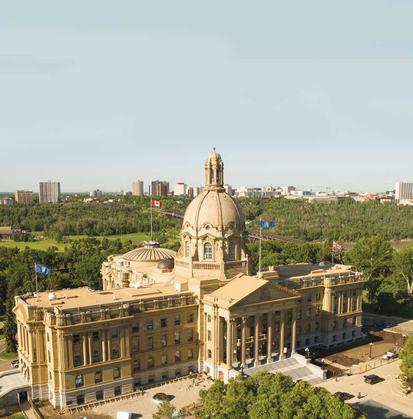
Restoring the grand old façade on the Alberta Legislature building to its original glory


Revolutionize your renovation or new construction project and save millions with Centra.
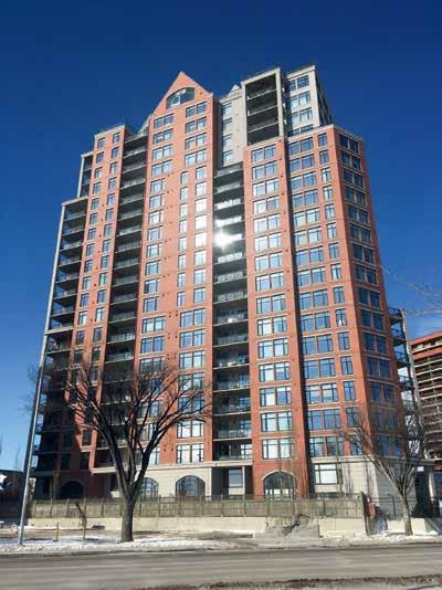
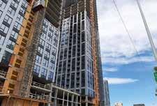
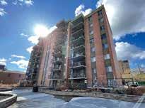
Due to recent successes, Centra has positioned itself as Alberta’s leading authority on windows, doors, and exterior remediation. Leveraging amendments to the Building Code, the company was able to save the owners of a 22-storey Edmonton tower up to $3.3 million on renovations.
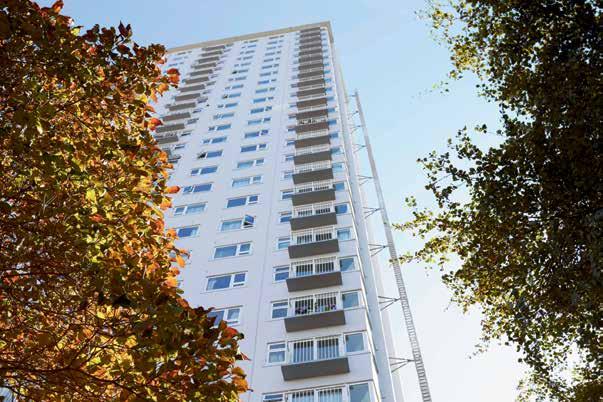

Value engineering doesn’t have to mean a loss in quality or performance. Beyond unprecedented cost savings, Centra’s solutions actually enhanced thermal efficiency and resident’s overall comfort, redefining what is possible in our industry.
Speak to Centra’s Experts to learn more about this project – and discover how they can help with yours.




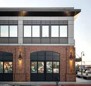

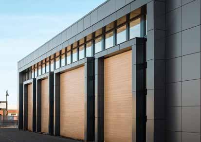
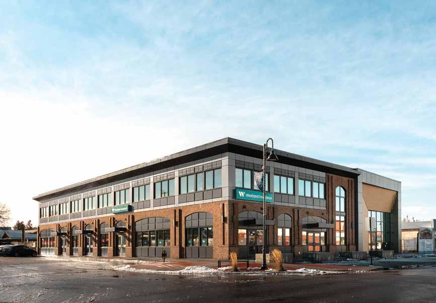


ü
ü
ü

GENERAL CONTRACTOR SPECIALIZING IN BUILDING ENVELOPE RESTORATION
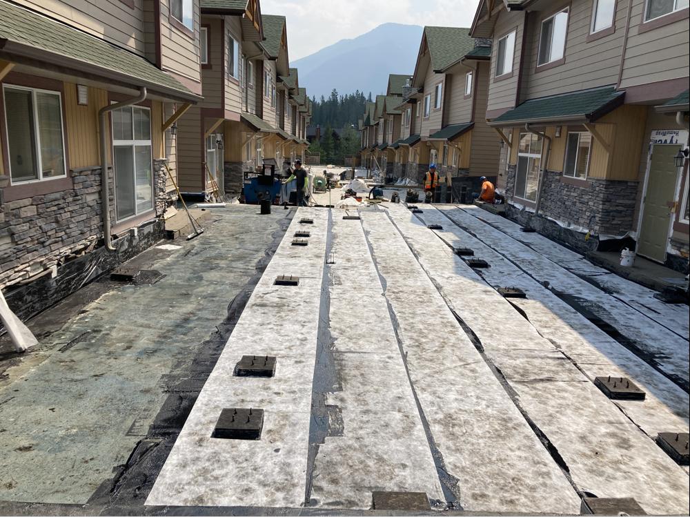
Offering self-performed specialty services, with the focus on quality control, sequencing, and scheduling. This provides a streamlined approach and helps reduce project timelines.
Self-performed
services


2
Concrete Repairs
O u r i n - h o u s e c o n c r e t e r e p a i r t e a m i s r e a d y t o f i x
y o u r c o n c r e t e i s s u e s F r o m s u r f a c e p r e p a r a t i o n a n d
d e l a m i n a t i o n r e p a i r s t o c r a c k i n j e c t i o n W e a r e a o n e - s t o p s h o p f o r a l l y o u r c o n c r e t e r e p a i r n e e d s

Landscaping
O u r i n - h o u s e l a n d s c a p i n g t e a m i s r e a d y t o t r a n s f o r m y o u r o u t d o o r s p a c e , b u i l d r e t a i n i n g w a l l s a n d h e l p t o
s t r e a m l i n e t h e r e - b u i l d p r o c e s s
e T a y l o r t e a m i s c e r t i f i e d t o w o r k w i t h m o s t m a j o r m a n u f a c t u r e r s
i n c l u d i n g B A S F , T r e m c o , S i k a , F l e x s t o n e a n d m o r e
Carpentry
O u r e x t e n s i v e t e a m o f c a r p e n t e r s w i l l g e t t h e r e - b u i l d
r i g h t ! W o o d r o t r e p a i r s , s t r u c t u r a l r e p a i r s , f r a m i n g , f i n i s h i n g a n d m o r e


IN THIS ISSUE


PRESIDENT / PUBLISHER
David Langstaff
MANAGING EDITOR
Kelsey James kelsey@delcommunications.com
SALES MANAGER
Dayna Oulion dayna@delcommunications.com
SALES REPRESENTATIVES
Brent Astrope | Colin James
Ross James | Mic Paterson
PRODUCTION SERVICES
S.G. Bennett Marketing Services
CREATIVE DIRECTOR / DESIGN
Kathleen Cable
PUBLICATION COMMITTEE
Bob Passmore | Ed Bushnell | Fred Edwards
Kevin McCunn | Jamie Murphy | Casie Chou
CONTRIBUTING WRITERS
Ben Hildebrandt | Tyler Hermanson
Justin Phill | Dr. Bas Baskaran
Suzanne Checkryn | Phillip Parker
Kashish Madaan | Priya Latha | Rob Pacholok
© 2024 DEL Communications Inc. – All rights reserved. Contents may not be reproduced by any means, in whole or in part, without the prior written permission of the publisher.
ABEC does not specifically endorse the editorial, products or services contained within this magazine. These products and services are presented here as an indication of the various possibilities in the Marketplace. ABEC wishes to advise the reader that sound Building Science Practices should be applied to any and all product or service selections. ABEC does not make or imply any warranties as to the suitability of any of these products or services for any specific situation. Furthermore, the opinions expressed in this magazine’s editorial content may not necessarily reflect the opinions of ABEC.” While every effort has been made to ensure the accuracy of the information contained herein and the reliability of the source, the publisher in no way guarantees nor warrants the information and is not responsible for errors, omissions or statements made by advertisers. Opinions and recommendations made by contributors or advertisers are not necessarily those of the publisher, its directors, officers or employees.
Publications Mail Agreement #40934510
Return undeliverable Canadian addresses to: DEL Communications Inc.
Suite 300, 6 Roslyn Road, Winnipeg, Manitoba R3L 0G5 Email: david@delcommunications.com
Hardie® Artisan Siding
Enjoy trusted protection and longlasting beauty with Hardie® siding that’s Engineered for Climate®
Hardie® fiber cement products are specifically engineered to resist moisture, cracking, shrinking and swelling, giving your home a look you’ll love with added peace of mind.


 Edward Bushnell President, ABEC (South)
Message from the ABEC South president
Dear members and supporters,
I hope this message finds you well as we approach the end of spring and look forward to the excitement of summer. At ABEC South, we eagerly await our annual golf tournament at Heritage Pointe Golf. This year, we are proud to be partnered with IIBEC CPC, and a portion of the proceeds will benefit the Inn from the Cold charity. Please join us for our next luncheon, scheduled for September and coinciding with our annual AGM.
Before moving forward, I would like to express my sincere appreciation to our speakers who have presented so far this year. Additionally, I extend a warm thank you to the Winston Golf Club for their hospitality and delicious lunches. I also want to take a moment to acknowledge our dedicated board members, along with countless others, whose hard work and commitment ultimately supports the organization. It is the time, energy, and effort of our community that not only make our endeavors possible but successful.
As we delve into the complexities of building envelope sciences, let us continue to embody the spirit of collaboration, innovation, and dedication that defines our community. Sustainability in building design stands as a core principle that guides our decisions and actions within the industry, and it cannot be overstated. Sustainable practices go beyond fulfilling an ethical responsibility and expand our ability to build a stronger foundation for generations to come. Our responsibility is to be proactive in minimizing our environmental footprint as we integrate sustainable practices and strive for energy efficient buildings.
Thank you for your continued support and participation.
Happy reading,
Edward Bushnell Christa van Dyk, C.E.T. President, ABEC (North)
Message from the ABEC North president
In 1997, a decade after ABEC was founded, I attended my initial Alberta Building Envelope Council meeting. Little did I know that 27 years down the road I would have the honour of being appointed as president of ABECN. I am overjoyed to write this as my first president’s message within this shared publication with Alberta Building Envelope South. We have some returning faces and a few new ones on ABECN’s board this year. As a collective, we are steadfast in our dedication to the education and advancement of the building envelope industry with Building Science Perspective.
What a fun and educational year 2023 was. ABECN continued our monthly Luncheon’s, we brought forth monthly Casual Night Series events, hosted our very first Ugly Sweater Casual Night, and spent a great afternoon at Victoria Park with our first ever annual ABECN picnic BBQ. As we move through 2024, we want to build on 2023 by providing more opportunities for our members to connect, continue to deliver thought provoking presentations, and grow the community at large.
The planning of events for the year ahead is well underway, with luncheons, casual nights, BBQs, and our joint golf tournament with CSC Edmonton Chapter (June 6, 2024). Keep in the know of all our upcoming events by following ABECN’s LinkedIn, checking out our website (www.abecnorth.com), or drop us a line at abecnorth@gmail.com to get added to our mailing list.
Thank you to my predecessor, Julien St. Pierre, for his enthusiasm, leadership, and commitment to ABECN and its membership.
My gratitude goes out to our board members, membership, authors and contributors of the articles in this publication, and speakers at our events. Your help makes ABECN what it is today!
Christa van DykSouth Board of Directors
ED BUSHNELL – PRESIDENT
FRED EDWARDS - PAST PRESIDENT
KRIS WALL – DIRECTOR
ANTON VLOOSWYK – TREASURER
STEPHEN HUNTER - EDUCATION COMMITTEE
MAIREAD WALSH – MEMBERSHIP
GREG MARTINEAU – PROGRAMMING
MIKE DIETRICH – SECRETARY
MARTY DEEMTER - EDUCATION COMMITTEE
JON SOLLAND - EDUCATION COMMITTEE
North Board of Directors
CHRISTA VAN DYK, C.E.T. – PRESIDENT
JULIEN ST. PIERRE, PENG – PAST PRESIDENT
NICOLE MALIK, RRO – TREASURER/SECRETARY
LINDSAY VERHELST – MARKETING
BEREKET ALAZAR, B.SC., RRO, P.L. (ENG) – MEMBERSHIP
GARRATT GRENIER, RRO, RPO, CTR – TECH/WEBSITE
MARLA SNODDON, PENG – PROGRAMMING
RYAN ASSELSTINE – EDUCATION
KEVIN MCCUNN, PENG – TECHNICAL REVIEWER
JAMIE MURPHY PL (ENG) – PUBLICATION
JOE MIS – DIRECTOR


CALENDAR OF EVENTS

ABEC South Schedule of Events
June 26, 2024:
ABEC and IIBEC CPC Golf Tournament
September 25, 2024:
September Luncheon
October 23, 2024: October Luncheon
November 27, 2024: November Luncheon
ABEC North Schedule of Events
June 11, 2024:
ABECN Casual Night Series – Air Barriers: Interior and Exterior @ Arcadia Brewing: June 11, 2024
June 20, 2024: BEC North June Luncheon –Choices: Exterior Wall Systems presented by Andrew Brassigton, CTR, Technical Area Sales Manager – Western Canada of Owens Corning at Highlands Golf Course
July 9, 2024:
ABECN Casual Night Summer Patio Social at Original Joe’s
August 14, 2024: ABECN BBQ at Victoria Park

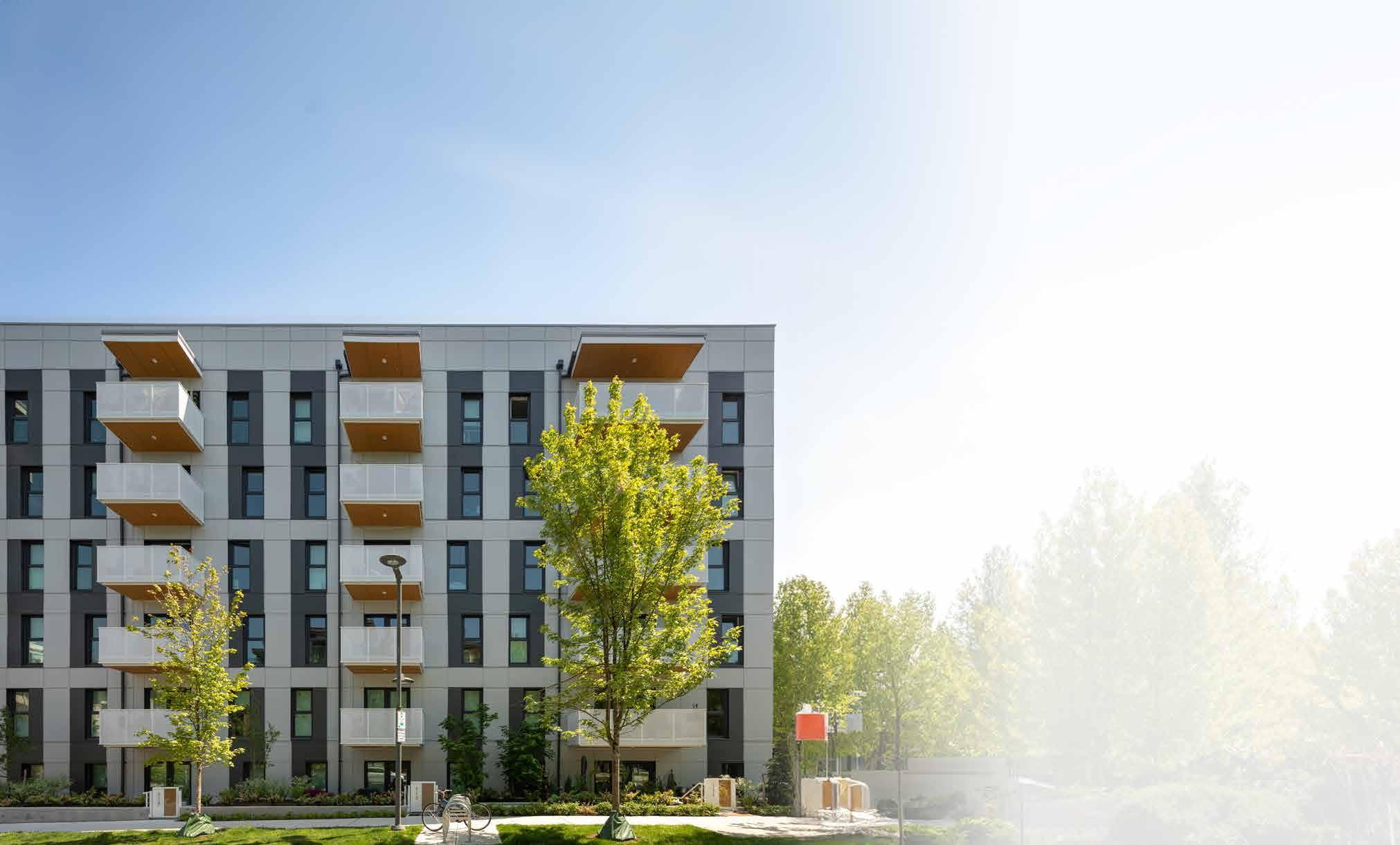


Windows + Door for Passive House Projects

Innotech Windows + Doors is a Canadian manufacturer of Passive House Institute certified windows and doors. With over twenty years of dedicated experience, Innotech delivers the manufacturing expertise and product performance required for Passive House and other highly sustainable projects.
The Defender 88PH+ System is a natural evolution in a proven history of manufacturing excellence. High-quality components, expertise in manufacturing, and robust testing and quality assurance programs result in highly durable windows and doors with superior thermal performance, air and water resistance, and dimensional stability.
Ask us about the Defender 88PH+ XI : the first Passive House Institute (PHI) cold climate certified window system manufactured in North America!
RESIDENTIAL DEEP ENERGY RETROFITS IN ALBERTA: EARLY PROJECTS AND A ROADMAP TO SUCCESS
 By Ben Hildebrandt and Tyler Hermanson
Ben Hildebrandt is an architectural technologist by training. Ben worked for several years in industry as a building science technologist. His focus with Green Building Technologies at SAIT is to oversee building science focused research. He also supports the development of educational curriculum to help increase the adoption of green, high performance building design and construction concepts.
In 2020, residential buildings and their various energy end uses accounted for 12.6 per cent of Canada’s greenhouse gas emissions, with 64 per cent of those emissions being from space heating and 20 per cent from heating domestic hot water. With 70 to 80 per cent of the buildings that will exist in 2050 already standing, retrofitting existing structures will notably contribute to the residential sector achieving Canada’s 2050 Net-Zero Emissions goals.
Retrofitting a home to reduce energy use from space heating and hot water is not as simple as hiring the lowest bid contractor to upgrade insulation and install high performance windows, heat pumps for space conditioning, and a heat pump hot water heater. Proper planning, building science principles, and house-as-a-system considerations are vital to a successful deep energy retrofit (DER).
Single detached, semi-detached, and row house buildings account for over 60 per cent of residential dwelling units, a significant portion of the residential retrofits that will need to be completed. These types of residential dwellings primarily utilize standard wood-frame structures resulting in similar envelope assemblies and techniques. They have

Tyler Hermanson is co-owner and Director of Innovation at 4 Elements. Hermanson is an architectural technologist by training and longtime energy advisor with over 15 years of experience in energy efficient, sustainable homes and buildings. Tyler leads a diverse team of green building experts while tackling the more complex energy and verification/certification projects as a Certified Professional Building Commissioner.
been the focus of retrofit case studies and training materials in Alberta funded by the Smart Sustainable Resilient Infrastructure Association (SSRIA). This work has been undertaken by a several entities including Retrofit Canada, The Southern Alberta Institute of Technology (SAIT) Green Building Technologies Access Centre (GBTAC), 4 Elements Integrated Design, SNAP Building, and Solar Homes.
This article will present the overarching concepts of residential DERs, a summary of work undertaken in three Calgary DERs, and the key process (or roadmap) for planning and completing a successful residential DER.
The what, why, and how of residential deep energy retrofits
When we speak of retrofitting buildings, we are referring to completing upgrades to the building (typically envelope and mechanical systems) with a goal of reducing its energy use.
Under the Greener Neighborhoods Pilot Program, Natural Resources Canada defines a Deep Energy Retrofit as “a major building renovation project in which the project will target at least 50 per cent annual energy use reduction (70
per cent energy use reduction preferred), while targeting 80 to 100 per cent GHG emissions reduction”. Another common goal of a DER is to achieve net-zero energy levels of performance (producing as much energy on site annually as the building consumes).
DERs are not simply completed to achieve energy and emissions savings through efficiencies gained. Other benefits from retrofitting homes and other buildings often include:
• Improved comfort and healthier living: Comfort is primarily achieved through improved thermal performance of building envelope assemblies and proper sizing and distribution of HVAC systems. The increased airtightness and proper mechanical ventilation have also been shown to provide improved indoor air quality resulting in improved aspects of occupant health such as reduced asthma/respiratory symptoms.
• Extending the useful life of the building: Typically, DERs capitalize on replacement of end-of-life envelope and HVAC components to implement higher insulation values, higher performance windows, and properly sized highefficiency heating and ventilation systems. This often results in an envelope and HVAC system equivalent to a new building.
• Increased resale value: The renewal of envelope and HVAC systems combined with increased efficiency can help increase resale values in comparison to homes with aging assemblies and systems.

Making Tomorrow Better Than Today
We believe that great design is only achieved through unique, bold, and inspired solutions that are centered on places that bring people together and keep them connected.
Discover METAFOR!

There are several categories of improvements typically undertaken in a residential DER:
• Improved airtightness and upgraded insulation: Air sealing and increased insulation levels are used to reduce heat loss through wall, roof, and foundation systems and at penetrations and transitions.
• High-performance windows and doors: New highperformance windows and doors can provide significant energy savings, particularly when replacing units that are 40-plus years old.
• Upgraded and efficient mechanical systems: Significantly reducing heat loss and air leakage through the building envelope results in the need to provide a new, properly sized HVAC system to ensure proper performance and ventilation rates.
• Renewable on-site energy generation: Combined with envelope and mechanical improvements, renewable systems are sized and installed to provide net zero energy performance.
• Electrification (fuel switching): One key step in moving away from the emissions of fossil (natural) gas in a home is getting rid of any fossil gas uses in the home including space heating, hot water, and cooking.
Three Calgary residential retrofits
The stock of residential DER candidates across Canada consists of many housing architypes constructed across many decades. Though the categories of DER

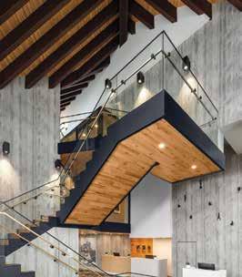

improvements are universal, the specific methods and strategies can vary significantly from project to project. Efforts are underway by Retrofit Canada and other organizations to establish best practices through documenting retrofit case studies, sharing methods and systems used, and lessons learned.
Three single family retrofit projects were completed in Calgary in 2022, supported by funding from SSRIA. These case studies capture three different exterior insulation strategies on three different single-family home architypes.
Project 1
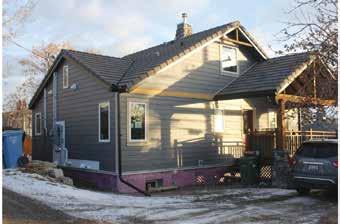
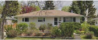
1950 two-storey in Highland Park, Calgary (Image 1).
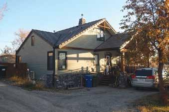
This home has been owned by the family since 1999 and has had several renovations with sustainability as the goal. Originally a simple 1950s bungalow, this home has been transformed into a high-performance inner-city home and was registered as a LEED project during a 2014 renovation. An office suite has been created in the basement of this home and the family resides on the main and upper floors. This project has taken a phased approach, with basement and mechanical upgrades having been completed in 2013, and the most recent renovation focusing on the above grade envelope (wall insulation, windows, and air sealing). Further renovations are planned, with the intention of fully electrifying and adding solar power as the final phase of renovations.
Before work in 2022, the home had an initial EnerGuide rating of 133 GJ* and an air leakage rate of 8.42 ACH50. The overarching goals of the retrofit work undertaken on this home in 2022 were to improve comfort and durability as well as prepare the home for future electrification and solar photovoltaic (PV) installation.
*The EnerGuide rating indicates a modelled total annual energy use of the home in Gigajoules.
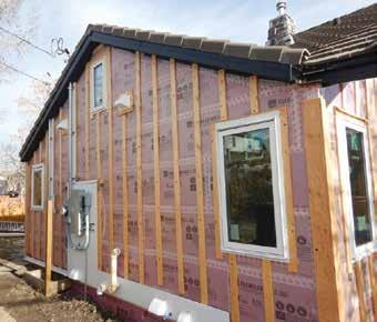
The original 2x4 walls in this home were uninsulated and in 2000 ~38mm (1.5”) of XPS insulation was added to the home’s exterior providing an estimated assembly thermal performance of 1.94 RSI (R-11). Part of the retrofit strategy of this home was to reduce heat loss through the addition of more exterior insulation. This was accomplished using ~100mm (4”) of low global warming potential (GWP) XPS insulation (Image 2) resulting in an end assembly thermal performance of 5.46 RSI (R-31). XPS was chosen as it provided the highest insulation value per inch which was needed to address minimal roof overhangs on the east and west sides of the home without modifications. ~100mm (4”) of XPS was also installed along the upper ~600mm (24”) of the foundation wall. Joints in the XPS were taped during installation to serve as the air control layer and efforts were made to connect with the airtightness plane of the roof assembly.
Due to cathedral ceilings and cement tile roofing with plenty of useful life left, no work was done to add insulation to the roof assemblies. Efforts were made to complete sealing where accessible to reduce air leakage through the roof assemblies.
Double-glazed windows which had been installed on the main and upper floors of the home in 2000 were replaced as part of the retrofit with new triple glazed PVC. Tripleglazed windows which had been installed in the basement
in 2013 were left in place. One of the two exterior doors was also replaced.
A heat recovery ventilator (HRV) had been installed in the basement suite in 2000 and an HRV was installed in the upper suite as part of this retrofit work. Finally, the main electrical service to the home was relocated and upgraded to 200 amps to accommodate future electrification of home heating systems and installation of solar PV.
Following this work undertaken in 2022 (Image 3), the home achieved an EnerGuide rating of 94 GJ (30 per cent improvement) and an air leakage rate of 4.52 ACH 50 (46 per cent improvement). With future work planned and accounting for previous energy improvements, this home is on track to achieve Net Zero emissions by 2050 (Figure 1).

Project 2
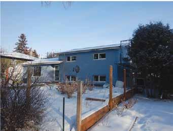
1957 split level in Cambrian Heights, Calgary (Image 4).
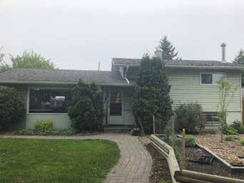
This DER presented an opportunity to align the family’s home with their sustainability and environmental values through a comprehensive retrofit that eliminated the home’s need for natural gas and prepared it for net zero with a future solar PV system. This retrofit included substantial interior renovation work, much of it completed by the homeowner.
Before work in 2022 the home had an initial EnerGuide rating of 134 GJ and an air leakage rate of 5.78 ACH50. The primary objectives of the retrofit conducted on this home in 2022 were to notably enhance comfort, minimize energy expenses, cut carbon emissions, and integrate infrastructure for a future solar PV array.
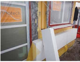
The original 2x4 walls in this home were insulated with fiberglass insulation with an estimated assembly thermal performance of 1.94 RSI (R-11). A ~200mm (8”) EPS Exterior Insulation Finish System (EIFS) was utilized to improve the thermal performance of the walls to an estimated assembly thermal performance of 7.57 RSI (R-43) (Image 5). EIFS was chosen as an aesthetic choice for a more modern look that would highlight the thick insulation on the outside giving the home a traditional European feel. The liquid applied weather barrier component of the EIFS provided an excellent strategy to improve the airtightness of the wall assemblies.
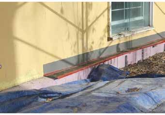
The thermal performance of the foundation walls was improved through installing ~100mm (4”) of low GWP XPS insulation. This below-grade insulation was installed by utilizing a hydro-vac to expose a 125mm (5”) channel around the perimeter of the home down to the footing. The insulation was then inserted, and the channel backfilled (Image 6).
The existing attic insulation of this home consisted of wood shavings and R-8 fiberglass batt insulation, providing an estimated assembly thermal performance of 2.64 RSI (R-15). The existing insulation was removed and ~50mm (2”) of closed-cell polyurethane spray foam insulation applied to the attic floor to seal any air leakage. The spray foam insulation was then topped with RSI 10.57 (R-60) of blown cellulose insulation providing an estimated assembly thermal performance of RSI 12.33 (R-70). Standing seam metal roofing was also installed to accommodate future installation of solar PV panels with minimal penetrations. The original double-glazed windows were replaced as part
of the retrofit with new triple glazed PVC windows installed. An additional window was added as part of the retrofit. The exterior doors on the home were also replaced. The fossil gas furnace was removed, an air-source heat pump (ASHP) installed to provide heating and summertime cooling in the home, and an HRV installed. The gas-fired hot water heater was also replaced with a hybrid air source heat pump hot water heater. Wiring was also installed to accommodate the installation of future solar PV. The electrical service of the home remained at 100 amps.
Following this work undertaken in 2022 (Image 7), the home achieved an EnerGuide rating of 49 GJ (63 per cent improvement) and an air leakage rate of 1.17 ACH 50 (80 per cent improvement).
This project was both a personal home and showcase for SNAP Building’s Deep Energy Retrofit services and achieved net zero energy performance with innovative low carbon wall systems, electrification, and a large solar PV
array. Quiet and comfortable, this updated home recently completed interior renovations and basement suite work for a minimally invasive full Deep Energy Retrofit.
Before work in 2022, the home had an initial EnerGuide rating of 152 GJ and an air leakage rate of 5.74 ACH50. The primary objectives of the retrofit conducted on this home in 2022 were to future-proof the existing family home and improve comfort and durability. One key goal of the retrofit was to achieve net zero on-site energy.
Prior to the retrofit work in 2022, the main exterior 2x4 walls in this home were insulated with fiberglass insulation and had ~25mm (1”) of XPS insulation with an estimated assembly thermal performance of 2.64 RSI (R-15). An addition on the home with insulated 2x6 walls had an estimated assembly thermal performance of 2.82 RSI (R16). In determining the insulation strategy for the home, the contractor/homeowner wanted to avoid the use of foam products and to utilize cost effective, locally available materials with simple construction. A Larsen truss system insulated with cellulose was selected to achieve these priorities. The exterior walls were stripped down to the sheathing and a ~200mm (8”) 2x2 Larsen truss assembly installed (Image 9) providing an estimated assembly thermal performance of 6.34 RSI (R-36). The exterior weather barrier membrane on the Larsen truss assembly was utilized as the air barrier and was tied into the foundation and ceiling assemblies.
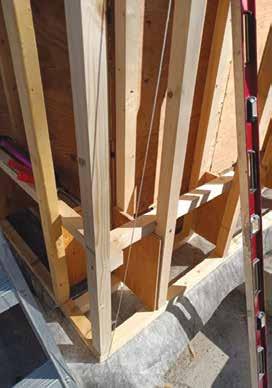
Of note for this project was the strategy used to provide a continuous air barrier between the wall and ceiling assemblies which was difficult due to a low roof slope and restricted access to perform detailed sealing. Closed-cell polyurethane spray foam insulation was applied around the perimeter of the attic, sealing between the new wall air barrier system and the existing ceiling polyethylene sheet (Image 10). Rooftop vents were installed towards the base of the attic to provide ventilation, as the spray foam blocked the previous soffit ventilation.
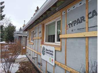
Image 10: Completed Larsen truss assembly of Project 3 with spray foam sealing between wall and attic assemblies.
Image 9:
Larsen truss framing on Project 3.
Due to a large amount of existing concrete flatwork along the front and side of the home, it was impractical to install any exterior below grade insulation on this home. The exposed foundation walls were insulated with ~100mm (4”) of low GWP XPS insulation. The crawlspace below the rear addition of this home was also improved with air sealing efforts, 1.41 RSI (R-8) batt insulation added under the heat run, ~100mm (4") XPS added to the exposed foundation and ~100mm (4") XPS installed on the perimeter skirt.
The existing attic insulation at this home consisted of wood shavings and R-8 fiberglass batt insulation, providing an estimated assembly thermal performance of 1.94 RSI (R11). The existing insulation was removed, and many hours of manual labour were undertaken to seal points of air leakage through the ceiling. Blown cellulose insulation was then installed to a level of RSI 10.57 (R-60).
The remaining original windows as well as two newer double-glazed windows were replaced as part of the retrofit with new triple glazed PVC windows. Two newer tripleglazed windows were un-touched. The exterior doors on the home were also replaced.
The fossil gas furnace was removed, an air-source heat pump (ASHP) installed to provide heating and summertime cooling in the home, and an HRV installed. The gas-fired hot water heater was also replaced with a hybrid air source heat pump hot water heater. The electrical service was relocated to the garage and upgraded to 200 amps. A 15.41 kW solar PV array was installed as a part of the retrofit work to obtain net-zero on-site energy performance.
Following this work undertaken in 2022 (Image 11), the home achieved an EnerGuide rating of 0 GJ and an air leakage rate of 2.04 ACH 50 (65 per cent improvement). Through electrification and the installation of solar PV, Project 3 achieved net-positive on-site energy performance, resulting in a reduction of 163 GJ compared to the homes pre-retrofit energy performance (107 per cent improvement).

The retrofit roadmap
While the projects noted above were underway, SAIT GBTAC led the development of A Guide to Deep Energy Retrofits. This was funded by SSRIA and was created in direct collaboration with Retrofit Canada, 4 Elements Integrated Design, SNAP Building, and True Aim Concepts. The guide was created to help address the skills gap slowing
the growth of the embryonic residential DER industry in Canada by providing a process for the successful planning and execution of DERs.
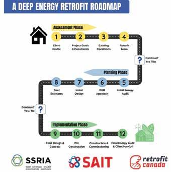
One key aspect of the guide is the establishment of the Deep Energy Retrofit Roadmap (Figure 2) to guide those overseeing and undertaking these projects through the three phases of assessment, planning, and execution of successful DERs. Key steps are outlined for each of these phases which incorporate essential integrated design process concepts. These steps and phases included in the roadmap are based on consultation with contractors, consultants and energy advisors who have been extensively involved in many successful DERs.
BEE BC 3/31/08 2:19 PM Page 1
Tel:(403) 287-0888 Fax:(403) 287-0880
Email:anton@beei.ca
Tel: (403) 287-0888 Email: admin@beei.ca
Street S.E.
www.beei.ca Anton J. Vlooswyk, P.Eng. Cel:(403) 651-1514
102, 4029- 8th Street S.E. Calgary, Alberta, T2G 3A5 www.beei.ca
What’s next for residential deep energy retrofits?
As the residential DER industry expands to meet the demand for home retrofits across Canada, two crucial elements are essential:
1. Understanding successful retrofitting methods used nationwide. Retrofit Canada is spearheading the creation of a publicly accessible repository of DER case studies and design insights, encompassing both successes and failures. The repository is slated for launch later in 2024. Existing case study data can be accessed at the link provided at the end of this article.
2. Comprehensive training is required to equip Canada's renovation industry with the necessary skills to effectively implement the Retrofit Roadmap and execute resilient DER projects. SAIT is collaborating with other postsecondary institutions and industry organizations to develop an extensive residential deep energy retrofit training program, supported by funding from Natural Resources Canada. A pilot delivery of this training initiative is scheduled for spring 2025.

This article has presented some of the early work in Alberta in the residential DER sector and has indicated work currently underway to further the industry. Drawing upon the wealth of knowledge possessed by those experienced in building science focused design, construction, and remediation work, we hold the key to propelling the success of residential deep energy retrofitting in Canada. By generously sharing our triumphs and insights from past projects, whether through contributing case study information to Retrofit Canada or actively participating in discussions and initiatives aimed at advancing DER work, we pave the way for a thriving industry.
The building science community's support is indispensable in laying a solid foundation for this burgeoning field. Let us not forget that neglecting this support now may only necessitate it later. n
INDUSTRY EXPERT Q&A with Kevin McCunn
Kevin McCunn is Senior Building Envelope Engineer in the Technical Services & Procurement Branch of Alberta Infrastructure. He supports the Ministry in the design, building, and maintenance government-owned and operated facilities to meet the needs of Alberta’s population. Kevin is a director for Alberta Building Envelope Council North. Read on to learn more about his background and career.
Question: How did you come to specialize in building envelope?
Answer: I stumbled into this career. At the UofA, structural engineering was my intention, but graduating during an economic bust, I was lucky to get a transportation planning position with government. After four years, I decided it did not suit me (maybe I wasn’t good at it), so I quit and went back to the UofA for Industrial Design and an Arts degree.
I landed a dream job in product design at a growing office furniture manufacturer. I was getting good at that when the company went out of business. I later worked for two more office furniture manufacturers that went out of business. Between those failures, there were many jobs, including a short time doing drafting for a curtain wall fabricator.
The experience in manufacturing and glazing, along with the P.Eng., landed me a job with a unitized curtain wall company supplying factory glazed windows, curtain wall, and skylights. That company went bankrupt too,
but restarted and went bankrupt again after I left. I stayed for 10 years, eventually overseeing a group doing small projects – many small projects, in fact. Small projects are mostly perimeter, where the envelope details get interesting. I did not realize at the time, but it was great building envelope training, setting me up for my current role with Alberta Infrastructure.
Q: How long have you been with your current employer?
A: I started in 2005 with what was then Alberta Infrastructure and Transportation. They were starting the Calgary Courts building, 25 storeys, double towers with a glass atrium between, but had no one with curtain wall or envelope expertise. They had searched for months but I was all they could get. The job turned out to be interesting and varied.
Calgary Courts was the first interesting and high-profile project. I supported our envelope consultant to assure the quality needed. This included four weeks in south Florida, observing installation, testing, and the failure of a full-scale curtain wall and precast panel mock-up, and then returning weeks later to retest the corrections. Florida sounds luxurious, so I received no sympathy for 10-hour days, six-day weeks, in a hot humid asphalt and steel test facility, with the mosquitoes, and the sunburn. Some days, we didn't even get to the beach!
More varied, and satisfying, was the work around Alberta that followed, traveling to visit old, moldy crawl
spaces and leaky attics, or investigate new moldy walls and leaky windows. I did not then, and still do not, get invited to buildings without problems or to projects going smoothly.
The Federal Building, now the Queen Elizabeth II Building, on the legislature grounds was the next allconsuming project. We faced tough questions, like how much spray foam can be applied to the inside of a limestone and clay brick wall without risking freeze thaw damage. Or how much discord and bad press can you have on a renovation and still have a successful project.
Q: What does your group do?
A: Technical Services is a small group of specialists of different disciplines. An internal document says we “maximize value for Alberta Infrastructure projects and all government facilities by championing best practices and standards development.” I think of us as internal consultants, supporting government buildings and working on behalf of Albertans.
We set standards for Alberta Infrastructure built hospitals, schools, and government buildings. Experience from constructing and maintaining our 2800 building inventory is input to these standards, and we consult with suppliers, manufacturers, contractors, and consultants. Our focus is on function, durability, maintainability, and longterm costs.
The Province is still racing to meet the demand for infrastructure, so
design reviews have become our most time-consuming task. We review at various stages from pre-design or schematic design through to final construction documents, for new projects and major renovations. As well as reviewing to our standard, we promote reliable and constructible details, identify problems with code, and advise on issues likely to cause problems.
We support project management teams, facility managers, and we participate in studies and special projects like modular classroom and modular courtroom programs. We get involved in diverse projects, such as heritage buildings, museums, fish hatcheries, a biosafety lab, etc. We support innovation in design and construction while trying to minimize the risk of unproven approaches and products. And we answer technical inquiries from inside and outside of government. It is interesting work.
In our spare time, we battle the bureaucracy, a monster we are part of, that threatens to consume us all.
Q: What has been the most difficult building envelope detail that you have seen in your career?
A: Most days, it seems like the most difficult is anything different than “the way we have always done it.”
The most difficult detail in my career would have been in the 90s, detailing perimeter air barrier connections for US designs and renos that did not have any air barrier. In the 90s, few Americans believed in air barriers. That may seem odd now, but back then, most Americans didn’t believe Elvis was dead or that presidents should lie about their sex lives.
Air barrier details at transitions and penetrations still cause the most grief in my work. Air leakage draws water from outside to where it will cause problems, and air leakage
carries moist air from inside to where condensation will form to cause damage. Air leakage becomes more important as we increase envelope performance, because even small leaks, if there are many, will waste more energy than we can save by adding insulation.
Q: What is the most innovative building envelop detail you have come across?
A: Innovation is a funny thing. I have seen both details and product so innovative they would require magic to work. That curtain wall company I worked for 25 years ago produced a glazing framing system with better performance than what is widely available today, but it was overly complex, maybe ahead of its time, and sales were not strong enough to support the product development and quality control that may have made it successful.
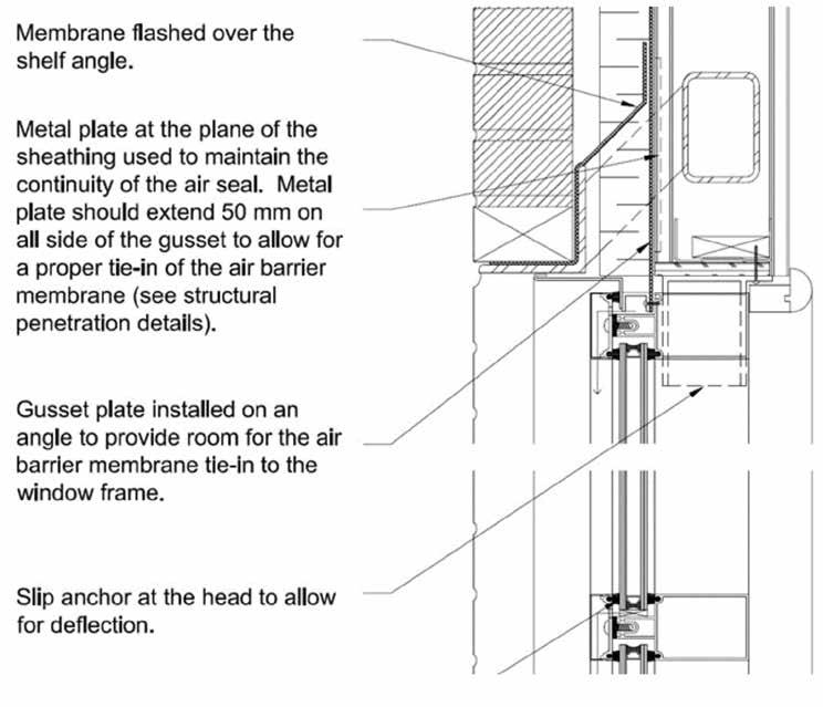
So, I will offer a more modest innovation that works, one that makes a difficult task easy: constructing a reliable air and water barrier connection to a curtain wall below masonry veneer in 2005 when I started this job and there is still a version in the appendix of Technical Design Requirements for Infrastructure Facilities.

This uses insulation over a selfadhesive membrane air, water, and vapour barrier. Instead of sealant, membrane is also the transition from wall to curtain wall, with the shoulder of the curtain wall on the plane of the sheathing so installation is easy, no origami required. The membrane is clamped and fastened to the curtain wall so it will allow some movement. The innovation is the sloped knife plate and the “gusset plate” in the plane of the sheathing, welded all around. Membrane installation from window to wall is easy and will be reliable. Without this, only slight movement will create a hole at the bottom of the knife plate that sealant will not fix. And there are typically many of these details on a project.
Q: What advancement in technology has had the largest positive impact on the building envelope? Largest negative impact?
A: Low emissivity glass coatings have made a big change. Windows and glazing provide the poorest insulating value of any significant envelope area. Typically, windows used to shed more than four times as much heat as the walls we were building. Low-e glass has reduced that heat loss by 60 per cent with little reduction in visible light transmission. Of course, walls and roofs have improved more, so now windows still shed more than four times as much heat as walls.
Q: In your opinion, what is the most important attribute that you see in a successful building envelope person?
BUILDING REVITALIZATION
SOLUTIONS
• Building Envelope Upgrades
• Mechanical (HVAC) Upgrades
• Electrical Upgrades
• Technology Enhancements
• Amenity Retrofits
For more information, please email Jamie Fleese at JPFleese@pcl.com
A: Because the discipline is relatively new, I think it is the desire to question yourself while still providing advice or solutions for the problem at hand. Ask: will that work, how does it work, can it be built, is there something better and, most importantly, am I missing a big hole somewhere?
It also helps to have a slightly delusional sense that we can make the world a better place.
Q: How do you see the building envelope discipline developing or changing in the future?
A: Demand for improved building performance will increase, driven by building codes and by building owners or occupants, and I keep hearing we are at a point of diminishing return from improved mechanical systems, so building envelope is next. But envelope performance will have to become more predictable and verifiable. The discipline will become more formalized and codified over time, like most other disciplines. If we are going to meet demand, our industry will have to develop systems for reliable improvement that can be applied widely to whole building types. It would be great to find envelope equivalents to heat pumps or condensing boilers, but envelopes are diverse, compound systems. Somebody needs to invent a parka for condos, but they need to look cool, or no one will wear them.
Q: If you could go back to that point in your career when you began to specialize in the field, what would you do differently?
A: With my history, I cannot responsibly offer career advice, not even to my past self. As I said to start, I stumbled my way this far (staggered? bumbled?). All I could offer is to keep trying to make things better but try not to take yourself too seriously. n


NECB BUILDING CODE CHANGES
 OBy Justin Phill, P.Eng, BEMP, LEED®
AP BD+C,Senior Engineer, Green Building and Energy Code in the City of Edmonton, SafetyCodes Permits Inspections group
Justin Phill’s passion is helping teams design high performance, low emissions buildings by sharing his expertise in building design, energy modelling, capacity building, and policy development. In his current role, Justin provides assistance to internal and external stakeholders on the energy codes, and also provides his expertise in green building initiatives throughout various departments within the City of Edmonton. He is committed to helping the City of Edmonton achieve its goal of becoming an emissions neutral city.
n May 1, 2024, Alberta will adopt the 2020 version of the National Energy Code for Buildings, and the 2023 version of the National Building Code (Alberta Edition). The 2023 NBC(AE) is based on the 2020 National Building Code, with some Alberta specific modifications.
The NECB generally applies to larger buildings that fall under Part 3 of the building code, such as retail buildings, apartments, and office towers. Section 9.36 of the NBC(AE) contains the energy efficiency requirements for smaller Part 9 buildings, such as single-family homes, smaller townhomes, and some small commercial buildings.
The 2020 versions of the National Building Code, National Fire Code, National Plumbing Code, and National Energy Code for Buildings were originally published in March 2022. These codes are model codes, meaning that various authorities across Canada are free to adopt them with or without modifications. The model codes are typically published every five years, but provinces have
the authority to adopt them at their discretion, as we’ve seen with the Alberta Edition of the National Building Code.
One major addition to both the NECB and Section 9.36 is the introduction of the tiered energy performance paths. Each tier requires the building to meet a certain energy performance level. In the NECB, there are four tiers, Tier 1 simply meeting the code, Tier 2 requiring a 25 per cent improvement over a building designed to NECB 2020, Tier 3 requiring a 50 per cent improvement, and Tier 4 requiring a 60 per cent improvement. The highest tier is intended to represent a net zero ready building.
In 9.36, Tier 1 is again simply meeting the code, and the highest tier, Tier 5, requiring a 70 per cent improvement over a building built to NBC(AE) 2023 9.36. The tiered path for 9.36 also requires buildings to demonstrate a heat loss improvement over a building built to 9.36. This means that not only does the building have to be energy efficient, but it also must have an improved building envelope to reduce heating
demand. This can be achieved with additional insulation or improving the airtightness of the building.
A Part 3 building designed to NECB 2020 is expected to use 5 to 15 per cent less energy compared to a building designed to NECB 2017. Some building archetypes will fall on the lower end of that range, some will fall on the higher end of that range. The following changes contribute to this improvement in energy performance:
• Lower thermal transmittance (U) values for above grade roofs and floors. The required U value for above grade walls increased slightly from 0.21 to 0.215.
• Lower thermal transmittance values for vertical glazing. The requirement is now 1.73, compared to 1.9 in NECB 2017.
• Skylights now have a separate thermal transmittance value. The requirement is 2.41, compared to 1.9 in NECB 2017.
• General decreases in allowable lighting power densities for most of the building and space types.
• Increases to equipment efficiency such as 90 per cent efficient gas fired hot water boilers (up from 83 per cent), 90 per cent efficient gas fired hot water tanks (up from 80 per cent)
Another significant change is the addition of whole building air leakage testing. In NECB 2017, only individual components had to meet specific air leakage targets (for example, metal and glass curtain wall had to have an air leakage rate not greater than 0.2 L/s-m2). There was no consideration of how these components were put together. Poor details of joining various assemblies could result in a high level of air leakage even if these individual components met their individual air leakage requirements.
NECB 2020 allows another option to conduct a whole building airtightness test. The air barrier system shall have a normalized air leakage rate not greater than 1.5 L/s-m2 when tested to ASTM E3158 “Standard Test Method for Measuring the Air Leakage Rate of a Large or Multizone Building” at a pressure differential of 75 Pa. Design teams can choose this method or can still choose the individual assembly method described in the previous paragraph.
If design teams choose to conduct an airtightness test, and choose to follow the performance path, they are allowed to use a lower air change rate in their energy model to take credit for the energy savings associated with decreased air leakage. This is something design teams could not take credit for in previous version of the NECB. For example, if the ASTM E3158 test result shows a rate
of 1.0 L/s-m2, the energy modeler can use this value in the proposed model (which is the model based on the actual design), and a value of 1.5 L/s-m2 in the reference model (which is the model which represents a building built exactly to the NECB 2020 prescriptive requirements). This results in 33 per cent savings, which can result in significant heating energy savings in our very cold Alberta climate.
There are some risks with claiming savings from an air leakage test. An energy model report is submitted to the Authority Having Jurisdiction to demonstrate that the building meets NECB 2020. The AHJ issues a building permit based on this report. Design teams will have to assume a target air leakage value in their building permit submission energy model report. The air leakage test is performed in the construction phase. If the actual air leakage is less than the value in the building permit energy model report, great! If the actual air leakage rate is higher, then the AHJ will request a revised energy model report to ensure the building still complies with NECB 2020. If the building had a low compliance margin in the design phase, this could put the building at risk of not complying with NECB 2020. Changes to bring the building into compliance during the construction phase could incur additional costs.
No significant improvement is expected for Part 9 buildings following 9.36 as the changes to that section are minor. The following changes contribute to this minor improvement in energy performance: • Increases to equipment efficiency
such as 95 per cent efficient gas fired furnaces (up from 92 per cent), gas fired tankless water heaters require an EF of 0.86 (up from 0.8)
Alberta will adopt Tier 1 for building following NECB 2020. Buildings following 9.36 will also adopt Tier 1, but with some modifications which the provincial government will announce. The provincial government has the authority to introduce higher tiers. There is currently no timeline on when higher tiers will be adopted.
The improvements in energy performance in the new codes are not expected to significantly change how we currently design buildings. NECB 2020 is approximately 10 per cent more stringent than NECB 2017, and 2023 9.36 is not significantly more stringent compared to the current 2019 9.36. Data from building permit applications in Edmonton shows the average Part 3 building complies by 6.6 per cent, and the average Part 9 building complies by 6.4 per cent. This means a typical Part 3 building would only require minor improvements to meet NECB 2020, and a typical Part 9 building is already approaching 2023 9.36 Tier 2.
These new codes will be a small, incremental step toward the federal government’s goal of net zero ready buildings by 2030. Higher tiers will push design teams to come up with new, innovative solutions to meet energy performance targets, resulting in fewer carbon emissions, and a better environment for us all. n
NEW ROOFING STANDARD AIMS TO HELP INDUSTRY PREPARE FOR CLIMATE CHANGE
 DBy Dr. Bas Baskaran
r. Bas Baskaran is researching the wind effects on building envelopes through experiments and computer modeling at the National Research Council of Canada. As adjunct professor at the University of Ottawa, he supervises graduate students. As a professional engineer, he is a member of Roofing Committee on Weather Issues (RICOWI), IIBEC, ASCE, SPRI, ICBEST, and CIB technical committees. He is a research advisor to various task groups of the National Building Code of Canada and member of the wind load committee of American Society of Civil Engineers. He has authored and/or co-authored over 250 research articles and received over 25 awards, including Frank Lander award from Canadian Roofing Contractors Association, Carl Cash Award from ASTM, and recently elevated as Fellow of IIBEC. Dr. Baskaran was recognized by Her Majesty Queen Elizabeth II with Diamond Jubilee medal for his contribution to the fellow Canadians.
Climate change isn’t a myth and roofs are especially vulnerable to those changes, says a National Research Council Canada representative.
“With climate change comes a higher demand on roofs due to greater and more frequent impacts of weather elements such as extreme wind, intense rain, and high temperatures,” research officer Bas Baskaran told participants at a seminar during the recent Buildings Show in Toronto.
The audience was given what may be the first in-person overview of a new and first-of-its-kind standard for the protection of low slope membrane roof systems.
Developed by the National Research Council Canada, with the help of roofing industry companies, groups, and associations, CSA A123.26 is intended for the industry to prepare for climate change. Work on its development first began in 2016.
Designed to exceed the National Building Code of Canada, the standard has a number of key features and benefits including providing a clear direction to designers of the owners’ expectation of the roof’s performance.
Other benefits include establishing a known standard for design and quality assurance right from the outset as well as providing a clear direction on how the roof is to be constructed.
The standard is a “consensus” one that incorporates the current knowledge of roofing trade organizations, the design community, as well as product manufacturers, said Baskaran, the moderator of a panel discussion titled “Are Canadian Roofs Ready for Climate Adaptation?”
“Roofs, when subjected to weather elements, are a major contributor for insurance claims,” said Baskaran, who opened the seminar by showing an image of scores of houses in a Florida community with roofs that were either destroyed or severely damaged by Hurricane Ian.
In Eastern Canada, the damage inflicted by Fiona has not yet been totalled up, he pointed out.
He urged designers, product manufacturers, and installers to adopt the standard’s “holistic approach” which takes into account load determination, resistance evaluation, and installation quality control.
It was his National Research Council Canada colleague and fellow panel member Flonja Shyti who provided some of the specifics.
Under the standard, there would be a three-tier system for climate resiliency: Bronze, the current rating; Silver, where design loads would be increased by 30 per cent; and Gold, a 50 per cent increase.
Some of the provisions include increased protection for parapets, such as the installation of bars or plates and fasteners around the parapets.
“Rooftop adds-on are the weak spots (to damage),” said Shyti, citing as examples gas lines, skylights, and curbs.
The standard calls for gas lines to be installed a minimum 304 millimetres above the finished roof line and properly secured against movement.
Under the Silver category, skylights and curbs should be placed at a minimum 355 millimetres above either the highest point above the finished roof surface or nearest to the overflow drain. If the Gold category was being adhered, the minimum height would be 457 millimetres, she said.
The panel included three private sector representatives, all of whom praised the intent of the standard and were somewhat critical of current practices.
In a talk titled “The Perfect Storm,” EXP’s Services Inc. director of building science for the Greater Toronto Hamilton Area presented a case study of a roof of a sixstorey institutional building that was severely damaged during a strong windstorm.
An investigation by EXP revealed the design specifications for its construction did not include site specific wind loads. But the fault didn’t stop there, said Sathya Ramachandran.
“The manufacturer provided a roof assembly that did not meet the performance requirements. And the installer did not meet the manufacturer’s installation instructions. If all
three (the designer, manufacturer, and installer) had done their job, the roof would not have been damaged.”
“We have to get security in roofing,” said the Roofing Contractors Association of British Columbia’s RoofStar technical adviser James Klassen, who used the acronym RFO to describe some of the ambiguities and less than clear language in design and contracts which contractors have to deal with.
He explained RFO stands for “roofer figure it out.”
The third private sector panel member was Richard Voyer, executive vice president of SOPREMA Canada, a manufacturer of roofing, wall, and other products.
“We have to get ready and educate ourselves for climate change,” said Voyer, adding some products now being used in roofing projects don’t meet the National Building Code of Canada.
“What are the consequences if you have on a roof a product that does not comply?” n
• MASONRY • SITE WORK • INSPECTION • STRUCTURAL STEEL
• STONEWORK
• RESIDENTIAL
• PUBLIC / INSTITUTIONAL
• HISTORICAL
• E.I.F.S.
• CONCRETE
• FOUNDATIONS
SPECIALIZES IN:
• PODIUM SLAB / ROOFDECKS
• EXPANSION JOINT APPLICATOR
• UNDERGROUND GARAGES
• HYDRODEMOLITION
• WINDOWS
• HIGHRISDE / LOWRISE
• CURTAIN WALLS
• COATING & CLEANING
• PAINTING / CAULKING
• STRUCTURAL REPAIR
THE REVAY CORNER: Temporary works –to specify, or not to specify?
 By Suzanne Checkryn, P.Eng., PMP, MBA –Director, Prairies at Revay and Associates Limited
Suzanne Checkryn is a professional engineer with more than 25 years of experience working in engineering, construction and consulting. Throughout her career, Suzanne has worked with major firms to complete projects on schedule and to overcome significant engineering and construction challenges. She has been involved in a variety of projects, including multibillion-dollar projects with complex engineering, supply chain, construction, project controls, risk management and change management requirements. Suzanne has extensive field experience working with owners, engineers, consultants, general contractors, subcontractors and suppliers.
At Revay, Suzanne is responsible for the firm’s Calgary office which services Alberta, Saskatchewan and Manitoba. She has been retained as expert for referee, mediation, arbitration and litigation. Suzanne also delivers training focused on claims avoidance and claims management to clients and industry associations across Canada and at the University of Calgary.
The last Revay Corner discussed the benefits of owners investing adequate time and money in the development of designs and specifications. When it comes to conventional design-bid-build projects, it is expected that the permanent works will be fully detailed within the designs and specifications.1 But what about the temporary works? In Revay’s experience, and as discussed in March 2024 lunch and learns for Construction Specifications Canada (CSC Edmonton) and the Alberta Building Envelope Council (ABECN),2 temporary works can prove to be an area of dispute; particularly if the scope and/or expectations are not clear. This column poses questions and considerations about temporary works, and whether projects would benefit from having detailed specifications for these scopes.
Depending on the type of project, contractors will be responsible for a varying degree of scopes that will not form part of the permanent asset. Examples of this include scaffolding, temporary power, and heating and hoarding,3 to name a few. It is fair to say that all projects have some degree of temporary works, including for such reasons as safety, to facilitate construction of the permanent works, and to protect the permanent works during construction.
When it comes to construction in Canada, it is typical for
temporary works to include heating and hoarding. Even when buildings are fully enclosed before the onset of winter, some form of temporary heating is usually required. As heating and hoarding is temporary, it is often left up to the contractor to (1) define how it will execute the work; and (2) determine how much it will carry in its estimate for the work.
In some cases, a contractor’s estimated costs for heating equipment, hoarding material, fuel, labour, and other potential “winter costs” across the site may be embedded in the general conditions costs (i.e., the “GCs”). In other cases, contractors may include “winter costs” within the pricing of specific scopes (i.e., underground utilities, slab on grade). In either case, how much has been included for “winter costs,” and how this work will be managed, may not be transparent. To the extent that the contractor is also not required to include temporary works in its execution plan or schedule, it may prove to be more difficult for an owner to assess whether the contractor’s plan and estimate were adequate.
Given the above, if the owner considers that the contractor is not adequately managing the temporary works, how can the owner justify its intervention as being due to contractor deficiency as opposed to owner interference? To avoid
encountering this ambiguity (including when the owner’s intervention follows a valid safety, security, or quality issue), owners may choose to provide clearer definition and expectations via detailed specifications. While the development of such specifications will come at a cost, doing so can mitigate other issues (and extra costs) later.
On the other hand, if there is a circumstance affecting the temporary works for which the contractor may be owed additional compensation, how can the contractor prove that its plan and estimate were adequate? To avoid encountering this ambiguity, contractors may choose to provide an execution plan and basis of estimate for the temporary works at time of tender. For example, contractors may include an explanation of when, and for what activities, “winter costs” have been included. Having this information will serve as important back-up not only for change orders and claims, but also for situations where extra costs are due to an owner’s instruction.
If an owner decides to produce detailed specifications for
temporary works, this can benefit projects by removing ambiguity and providing more alignment and transparency. This will come at a cost for the specification development, and possibly result in the contractor carrying more costs for temporary works than it otherwise would have. As every project is different, studying the individual risks and unique features of each can help guide an owner, and its consultants, in deciding how much definition is warranted for temporary works and how temporary works can best be monitored during construction. n
1 It is acknowledged that conventional design-bid-build projects may involve specific design-build scopes.
2 Presentations by Revay Senior Consultant Robert Wirth; presentation content developed in concert with CSC Edmonton and ABECN.
3 The term “hoarding” may also refer to temporary fences or barriers for worker or public safety. For the purposes of this article, “heating and hoarding” refers to Winterrelated temporary works. n
High Performance Engineering Services
Building Enclosures
Building Energy Modelling
Façade Engineering
Waterproofing Investigations & Evaluations
RJC to Learn and Do More.


DESIGNING FOR HIGH HUMIDITY ENVIRONMENTS – FURTHER THOUGHTS
Presented to:
Alberta Building Envelope Council (South), January 22, 2020
 PBy Phillip Parker
Phillip Parker has more than 25 years of progressive experience delivering complex projects and leading diverse teams to solve multi-faceted challenges. Holding roles as a consultant, educator, constructor, and owner, he has wide and varied experience across the industry spectrum.
An expert in hygrothermal simulation, Phil is one of a handful of Certified WUFI instructors outside of the US Department of Energy. Phil currently practices at Introba in Calgary where he delivers building envelope commissioning projects, building science, and supports the firm's other practice areas.
ast year, I presented a session to the Canadian Prairies Chapter if IIBEC which explored the challenge of envelope design for high humidity occupancies with an emphasis on roofing. Humidity as a challenge for designers and builders in Canada is not a new topic. In fact, it is so fundamental to Canadian construction that Neil Hutcheon chose the topic for the first ever Canadian Building Digest published by the Division of Building Research (DBR) at the National Research Council. In CBD-1 Humidity in Canadian Buildings (1960) Hutcheon noted:
“Humidity is one of the most important of the topics that are of special concern in Canadian building design and operation. Low outdoor temperatures in winter give rise to condensation on and in walls and windows and tend to produce low relative humidities indoors. When even moderate humidities must
be carried within buildings serious difficulties can be expected unless the designer appreciates fully what humidity is and how it relates to building performance.”
Regrettably (or rather reassuringly), nothing has really changed in the ensuing 60 years since that writing. Our analysis tools have improved … more on that later … and new materials have emerged onto our market, but the underlying physics remain. Of greater concern, we as an industry have evolved very little. Last year I wrote:
“[Envelope] design has a longfounded basis in both science and practical application – in essence we know how to make [envelopes] that work. But much of the design tools and practical case examples are founded on or rely upon fairly typical conditions. Interior conditions within most residential or commercial occupancies are fairly well understood and controlled with typical HVAC equipment. But what happens or
can happen when those conditions are altered or uncontrolled? Hotter and humidified – either directly or indirectly, interior occupancies sometimes with aggressive chemicals in the air can pose special challenges in roofing and envelope design and may preclude the use of typical materials and assemblies.”
In essence, we rely on our past experience as an analog to predict future performance which while emotionally comforting may be intellectually disingenuous. In a world where the rate of change appears to be accelerating, relying on the past seems an increasingly risk fraught proposition. Further, what if the typical analogs just aren’t representative of the conditions we are actually dealing with?
So, where do these special buildings exist? How about in every Canadian community – the Recreation Centre. Hockey rinks, curling sheets, ommunity pools, even hot yoga studios… oh, and the odd industrial
or commercial facility, such as composting facilities and commercial laundries. All of these occupancies and more can present challenges to envelope design and construction. Slightly more insidious are recent design changes in response to social enlightenment, sustainable construction objectives and new codes and regulations. The recent emergence of “white,” “cool,” “high albedo,” and other euphemisms for non-traditional roofing systems has revealed vulnerabilities. And in an industry steeped in traditions, yes, I do consider materials with less than a 40year track record to be “new” or “nontraditional.” Any system or material with less than two full life cycles under its belt is “new” to me. More recently, the implementation of NECB 2011 (then 2015 and 2017 in very short order) has seen typical commercial roof insulation levels jump from R-10 (2”) or R-20 (4”) for a good roof to a minimum of R-40 (8”). What are some of the unintended effects of such radical change? Time and possibly the computer, will tell. Recent emphasis on sustainability has increased our
desire to design more efficient new structures, leading to the development of more energy efficient envelope and roofing assemblies and the use of non-traditional and sometimes even novel assemblies – many of which do not have a substantial case history to commend them. This combined with non-typical interior conditions can be a recipe for disaster!
Let’s set some general parameters for what would constitute a high humidity or special environment. These are my guidelines and are supported generally by ASHRAE and other standards/design guidelines.
• Interior operating temperature exceeds 25°C for prolonged periods (i.e. more than eight hours) on a repeating basis.
• Interior operating humidity exceeds 40 per cent regularly (several times per week or seasonally).
• Aggressive chemicals in interior air. So, what does this all mean? Let’s look at vapour pressure – the pressure exerted by imbalances in moisture vapour within two separated bodies of air – in the case of a typical Canadian
community pool condition:
• Wintertime exterior conditions: -20°C, 30% Rh vapour pressure 38Pa
• Interior operating conditions: 25°C, 45% Rh vapour pressure 1425 Pa
The net vapour pressure acting outwards on the roof and envelope assemblies is 1.4 KiloPascals! Let’s put that in perspective – the Calgary ground snow load from the Alberta Building Code is only 1.1 kPa and the basic 1/50year wind load is a measly 0.48 kPa. So, the pressure exerted on the envelope by invisible water molecules in the air is greater than the snow load and the wind load –why aren’t we designing for it? Well, we should be.
Where is all this water vapour coming from? Let’s revisit the community pool. A typical small recreation pool can be considered as follows:
• Pool hall building (aatatorium): Volume 2500 m3
• 25m standard pool length with eight lanes (standard activity): Area 300 m2
• Water temperature 29°C

• Typical outdoor conditions: Winter -4°C, summer 28°C
When the pool is occupied using an activity factor of one gives 60L/ hour of evaporation and during unoccupied hours (activity factor 0.1) yields 17L/hour of moisture given off to the air. Wave pools, hot tubs, and water slides all have activity factors > 1.0 and increase the evaporation rate. Seen any community pools without these features lately?
Now certainly it can’t be as bad in ice rinks, right? Not so fast – we still have a giant puddle of water in our building it just happens to be frozen. The saturation vapour pressure over calm water and ice are virtually identical down to -5°C, which is about the limit of most ice making plants. Also, the wintertime condensation potential within roof and envelope assemblies is higher (about two times) for ice rinks because of the generally colder temperatures throughout the roof/envelope assemblies.
So, what can we do about this?
Certainly, mechanical ventilation and, if possible, dehumidification are important but be aware that the mechanical designer is concerned with the comfort of occupants and the quality of the indoor air. Design standards for indoor air quality in pools and ice rinks focus the ventilation at the level of the people and not up near our roof assemblies. Ice rinks, pools with water slides and diving towers tend to be quite high roofed and the mechanical designer is compelled to direct the ventilation where the people are – at the pool level/ice surface or bleachers. So, there is no real ventilation at the roof or upper walls.
Going back to our typical small pool the minimum ventilation rate
necessary to control that condensation is about five ACH with ASHRAE recommending rates between six to eight ACH.
Our mechanical design colleagues aren’t insensitive to our plight with the ASHRAE Applications Handbook (Chapter 4, 1999) noting:
“Humans are very sensitive to relative humidity. Fluctuations in relative humidity outside the 40 per cent to 60 per cent range can increase levels of bacteria, viruses, fungi, and other factors that reduce air quality. For swimmers, 50 per cent to 60 per cent relative humidity is most comfortable. High relative humidity levels are destructive to building components. Mould and mildew can attack wall, floor, and ceiling coverings (as well as your E&O insurance policy … I added that, not ASHRAE); and condensation can degrade many building materials. In the worst case, the roof could collapse due to water condensing on the structure.”
Well, that is a cheery outlook! Sorry to be a bit dour, but the worst case has happened, more than once.
The suspended acoustic ceiling, some lights, and other equipment suspended from the roof of a BC lower mainland community pool crashed into the pool while it was full of little swimmers. While traumatic, luckily there were no serious injuries. How do we deal with these problems? The first step is understanding what you are up against. There are a number of analysis methods which will help you understand the challenge and pick materials and assemblies that will give you a fighting chance.
Old school methods include the Glasser method, which is a simple steady state analysis using a psychrometric chart that you can get
from the internet or any decent HVAC supply outfit. The problem with the Glasser method is it is steady state and the world… just isn’t. Weather fluctuates, occupancy loads change, and materials degrade over time.
Other options include ASTM C755 (2015) Standard Practice for Selection of Water Vapour Retarders and ASTM E241 Standard Guide for Limiting Water Induced Damage to Buildings.
Understanding the complex interactions between heat, air, and moisture movement within assemblies of new high performance buildings or buildings with special occupancies is key to ensuring longevity and durability. These coupled interactions are dynamic, multi-dimensional phenomena and are not adequately modeled using one dimensional or static analysis.
Known commonly as hygrothermal or HAM (heat air and moisture) simulation, modern numerical methods based on the finite element/ finite volume principle are employed to predict the transient thermal and hygric behaviour of multi-layer building assemblies exposed natural weather and user defined interior conditions. The use of hygrothermal computer simulation programs is supported by various standards including ASTM E-241 (2000), WTA Guideline 6-2-01 and ASHRAE/ ANSI 160 (2007). For the purposes of this brief, the focus will remain on programs with support in North America.
WUFI®Pro (Wärme und Feuchte instationär) is a one-dimensional heat and moisture transfer model that is used to assess the hygrothermal behavior of multi-layer building envelope assemblies created at the Fraunhoffer Institute for Building
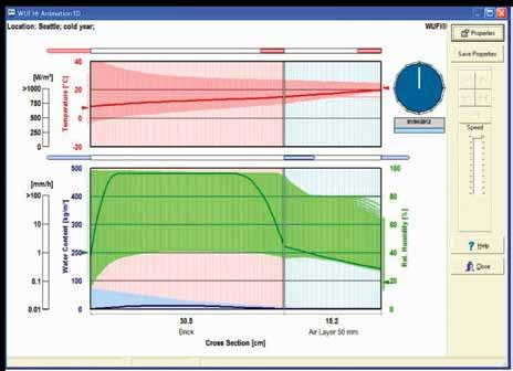
Physics in Germany, a partnership with the Oakridge National Laboratory (ORNL) resulted in the development of a North American version. Currently, WUFI is in use in both Canada and the United States. It uses measured weather data, including driving rain and solar radiation, allowing realistic simulations of the behaviour of assemblies under exposure to weather. Its calculations are based on detailed data regarding vapour diffusion and liquid transport in building materials and have been validated by measurements obtained in the laboratory and outdoor testing. One of the latest upgrades allows for the accounting of imperfections within the components and assemblies by introducing moisture sources and adding vented areas. WUFI can be used to test potential solutions as well as assess deterioration mechanisms within building envelope assemblies. It can assist with estimating the drying times of materials having trapped or concealed construction moisture, investigating the danger of interstitial condensation, or studying the influence of driving rain on exterior building components. The program
can also help to select repair and retrofit strategies with respect to the hygrothermal response of a particular assembly subjected to various climates. This allows the comparison of different designs with respect to total hygrothermal performance. WUFI is, in essence, designed to model only porous materials. Metals, glass, and other effectively impermeable materials are cumbersome to model and require
a certain manipulation of program settings. WUFI is only able to model one-dimensional systems. The interactions between bridged materials, such as insulation and framing, cannot be accounted for. Because of the limitations noted above, unless one is an expert in verification of input data, the model is limited to the value of “warning – change your design to one that is more safe.” This is sufficient and appropriate for most design assignments.
HygIRC is a Canadian program developed for research purposes by the Institute for Research in Construction (IRC) of the National Research Council (NRC) of Canada. The program was part of MEWS (Moisture Management for Exterior Wall Systems) Research Program as a way to analyze the building physics in low-rise, wood-frame construction. Initially designed for research purposes, HygIRC is slowly being introduced into the commercial sector. A major benefit of HygIRC is the ability to not only identify the
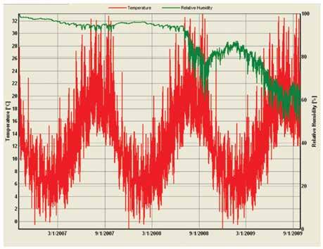
area of greatest moisture build-up, but also the wetting period duration (Mukhopadhyaya et al 2003). HygIRC not only pinpoints a potential problem, it also aids in determining the magnitude and severity of that problem.
The newness of this software means that its accuracy and reliability are still uncertain and can only be confirmed by long-term, controlled experiments. As such, the program is constantly undergoing adjustments to its algorithm and set-up. Another drawback is the RHT scale that is unique to this program. The RHT scale applies a linear weight to relative humidity and temperature; this assumption may not always be the case. Only through long-term, controlled experiments will the validity of the RHT assumptions be confirmed. Also, the RHT scale is not immediately intuitive. Unlike HygIRC’s contemporaries, which can give numbers and results that can be easily interpreted, the RHT scale requires a certain amount of background knowledge and understanding of how that scale was derived.
Computer simulation programs give other design professionals the ability to model designs that would be difficult to calculate otherwise. Simulations quickly verify a design’s expected performance, highlight problem areas for revision, or predict potential long-term problems in novel, un-tried assemblies. While not a substitute for good judgment, judicious use of simulation programs can highlight potential deleterious side-effects and also pin-point potential improvements to proposed assemblies, increasing efficiency and reducing costs.
General guidelines for the design of roofing systems and the use of computer programs for predicting such problems were presented by Andre Desjarlais and Nan Byars in their paper Predicting Moisture Problems in Low-Slop Roofing (Thermal Envelopes VII). They presented four tenets which are equally valid for the envelope as a whole:
1. The average yearly moisture content of an [envelope] must not increase with time
2. No condensation can occur under the roof membrane (…behind the air barrier?)
3. If a leak occurs in the roofing system, no condensation can occur on the deck (if insulation is compromised, the structure should still be condensation free)
4. If a leak occurs in the [envelope] the drying time will be as short as possible
OK you say thanks for trying to scare and intimidate us – but we’ve been doing this for years and yes a few problems do pop up but these are related to sloppy construction or bad building operations. I concede the point that a poorly constructed envelope or a badly operated building are disasters waiting to happen. David Scott and Mark Lawton present some fairly obvious cases in Envelope Durability Problems in High-Humidity Buildings. They concluded the following based on lessons learned from a series of case studies involving high humidity occupancy buildings: “Some people would argue that the construction industry has improved its knowledge and methods. Indeed, the concept that high interior humidity, air leakage points, and ex-
filtrating pressures result in moisture and durability problems is hardly surprising. However, the authors would note that in practice we see very similar design details employed in current designs. The key difference in the example buildings presented here and in many buildings being constructed today is simply the time it takes for the problems to appear. The industry has yet to find ways of addressing the concern in a consistent manner.
Some general conclusions to be drawn from these examples include the following.
• Mechanical pressurization of building envelopes that are required to maintain high relative humidity must be kept at an absolute minimum…
• The lack of intentional pressurization did not negate the need for air barrier continuity…
• Operating buildings at higher negative pressures is contrary to the design thinking of most designers, and they will need convincing that it is a valid design approach. Negative-pressure operation still requires attention to airtightness to avoid cold drafts and perimeter-zone heating problems and may require special measures such as vestibules at entrances.
• A common factor in the examples was the lack of continuity of the air barriers at the interface between different assemblies and materials and, to a lesser extent, the joints between similar materials…
• The specific problems discussed were related primarily to design, detailing, and material selection rather than poor construction…” New and emerging materials can
present hidden and often unexplored problems. In Condensation Problems in Cool Roofs, Kunzel, Bludau and Zirkelbach all writing for the German Institute of Building Physics (IBP) explored a problem with condensation in “cool” roofs – a sustainable design strategy intended to reduce building energy consumption and control urban heat islands. The change or course was away from traditional roofing systems which were darker in colour. What they found was roofs designed to meet the tenets of Desjarlis and Byars that had the capacity to dry to the interior (i.e. a weak interior air/ vapour barrier on purpose) tended to accumulate moisture by vapour diffusion but that dark surfaced roofs generated enough heat to drive off the accumulated moisture while their “white” or “cool” counterparts did not. The disparity was worse the “colder” the location explored and for cold areas (i.e. Calgary – I assume most of you are still in shock from last week) the problem becomes unstable, and the roof accumulates moisture over time to failure.
What about those aggressive chemicals you mentioned in the opening?
And now onto the gory bits. Pools in particular and those that use some form of chlorine can be particularly dangerous. A by-product of the chlorine disinfectant process is a chemical known as Chloramine – a derivative of chlorine which is highly corrosive to a wide range of metals including most stainless steels. But I thought stainless steel was good? I’m not saying it isn’t – it just doesn’t belong anywhere near a chlorine disinfected pool.
The photo (top right) is of a stainless steel bolt supporting the waterslide in a major community recreation pool
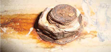
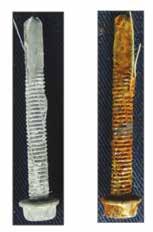
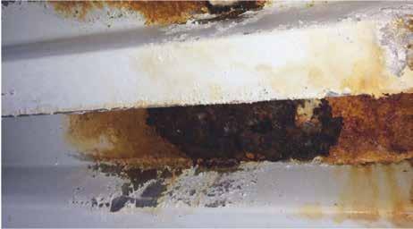
after only a few years in service. The irony was that the pool was supposed to be Ozone disinfected but was changed to chlorine for cost savings.
Metal deck fairs little better and often the corrosion origin is at fastener penetrations. The interaction between the hot work steel of case hardened self-tapping screws and the cold worked deck steel as well as the galvanizing is a corrosion cocktail once acids (like chloramine) or salts are introduced.
But we use corrosion protected screws to fasten down our gypsum sheathing and insulation boards – surely those will be ok! Right? The manufacturers give us test data that say they are good for 3000 hours? Well, yes … and no. Let’s look at the way they get tested and how we use them.
For one of Calgary’s new recreation centres, RJC, the Architects, and the Builders all participated in a study to see just how this all works in the real world. The two photos above right show a pristine (left) corrosion protected screw taken directly from the packaging and another screw that was driven into metal decking and then removed prior to testing (right). Both were exposed to 750 hours of salt fog exposure. Note that the manufacturer’s published data is based on testing pristine screws.
We also wanted to see how the screws, decking and structural steel all interacted. The photo below shows our experimental test set-up with screws and deck samples.
Metal decking was also affected which correlated with observations we had
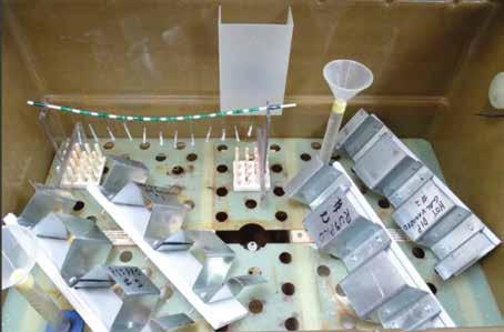
made in the field on older pool buildings.
Then what are the effective design strategies to overcome these challenges? The first is have a very robust, continuous, and effective air and vapour barrier. Pools and ice rinks should be controlled to slightly negative pressure, but you can’t rely on the mechanical system not being monkeyed with by a well-meaning building operator or maintenance contractor.
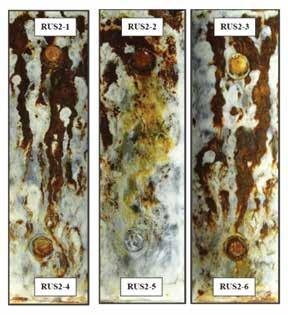
What do I mean by robust? Well, I think no vapour barrier is out and we can scratch off loose laid polyethylene and kraft or asphalt building paper – we need to be focused on adhered bituminous products or something of that ilk.
Review the details carefully and challenge the architects/envelope/ roofing designer to be explicit on penetration details and interfaces. Don’t accept that these interfaces may be another trades responsibility

or problem – the courts won’t see it that way. Understand the building use up front – if there are special environments be open that these are special and take the necessary steps to ensure they function for the life of the facility.
Look towards adhered systems including the gypsum and insulation. All those fasteners are potential air and water vapour leaks, and the dissimilar meatal corrosion is a problem that you can’t avoid. Eschew long cantilevers, tall parapets, and unvented soffits. These are difficult areas to keep airtight and the projected cooling surface is simply too great to avoid condensation.
Commissioning is your friend! Use mock-ups, pre-construction conferences, testing, check sheets, and a documented and auditable quality control program. Use the tables and procedures in CSA S-478 Guideline on Durability in Buildings to document the environment, aggressive conditions, anticipated durability, and the consequence of failures when they inevitably occur.n
TRANSFORMING FACADE CONSTRUCTION: HARNESSING BIM FOR EFFICIENCY AND PRECISION
 By Kashish Madaan and Priya Latha
Kashish Madaan holds a Bachelor of Technology in civil engineering from Bharati Vidyapeeth University in Pune, India, and a post graduate certificate in BIM Management from George Brown College in Toronto. He is currently leading the VDC/ Digital Construction department for Bird Construction in Southern Alberta and Interior BC region. An ardent advocate of knowledge sharing, Kashish has actively collaborated with various institutions such as George Brown College, Southern Alberta Institute of Technology (SAIT), Calgary Construction Association and Concordia University, lending his support to their BIM/VDC programs. With a deep-seated interest in cutting-edge engineering technologies, he firmly upholds the view that BIM holds significant potential across the entire project lifecycle, including Operations & Maintenance and Facility Management.
Introduction
In contemporary architecture and construction, building facades hold significant importance, serving as the face of modern buildings and representing their character. The integration of Building Information Modeling (BIM) has emerged as a transformative force, reshaping the way building facades are designed, constructed, and managed. The era of conventional blueprint sketches and disjointed data management systems has passed. Today, BIM takes center stage, presenting integrated solutions that streamline operations and elevate effectiveness throughout the industry. This article explores the pivotal role of BIM in enhancing the efficiency and precision of facade construction, delving into various aspects of its application and the benefits it brings to the industry.

Priya Latha is a seasoned professional with a background in structural engineering from India and specialized training in BIM Management from George Brown College, Canada. With expertise in scan-to-BIM projects, she now serves as a Senior Digital Construction Coordinator at Bird Construction, where they spearhead innovation and efficiency. She worked on multiple projects, showcasing proficiency in model coordination, laser scanning, quality checks, as-built Model verifications, and Facility Management Model deliverables. Her contributions ensure project integrity and long-term operational success.
Enhancing facade construction efficiency through BIM
1. Streamlining curtain wall installation
The conventional method for installing curtain wall panels involves installing curtain wall anchor embeds into concrete, manually taking measurements on-site, comparing them with 2D fabrication drawings, and then proceeding with installation of panels. If on-site measurements of cast embed differ from the panel size, extensive coordination with the concrete sub-trade is necessary. This process is labor-intensive and timeconsuming due to the manual effort involved. However, leveraging laser scanning technology and 3D fabrication models has significantly improved efficiency. By overlaying point cloud data, generated from laser scanning on-site conditions, onto the 3D fabrication model, real-time

communication is enhanced. Stakeholders can directly assign issues, such as discrepancies in measurements, to the relevant parties. Examples provided in Images 1 and 2 illustrate such comparisons, allowing sub-trades to review on-site curtain wall embed measurements for adherence to acceptable tolerances. If discrepancies exist, stakeholders can access the measurements on their mobile devices via an application to view the issue in 3D.
2. Managing penetrations on facade panels
During the construction phase, extensive coordination is necessary before planning the installation of the building facade. A significant aspect of this coordination involves managing the placement of exterior mechanical openings. While certain panels can have on-site openings created without difficulty, most panels are prefabricated in shops with precisely cut openings to accommodate these mechanical elements. Images 3 and 4 exemplify scenarios from a project, depicting pre- and post-coordination situations. Image 3 illustrates the need for adjusting the panel size to accommodate a duct, while Image 4 displays the corrected size and the addition of louver to the facade model. Subsequently, the revised model was shared with the shop for fabrication.


Another example is for electrical/security or similar devices that are required to be mounted on the exterior of the building. All such openings are coordinated and fabricated at the shop. The size and location of all penetrations are provided to the façade contractor to update the façade model with openings. The electrical/ relevant sub-trade then reviews and confirms to proceed with the fabrication at the shop. Image 5 shows the curtain wall model with pink colored cutout for various devices.
3. Optimizing canopy installation through laser scanning
Laser scanning assumes a pivotal role in the installation of canopies, as the point cloud data can be superimposed onto the fabrication model to assess the canopy design vis-a-vis the on-site cladding supports necessary for canopy installation. The process begins with on-site casting of canopies according to the architect's design. After casting, a scan of the canopy is conducted to facilitate coordination with the cladding sub-trade. This ensures the design of supports around the canopy aligns appropriately and enables coordination for the fabrication of the cladding's actual shape at the shop. Such 3D reviews Comparison of on-site conditions (Paintcloud data)
greatly benefit the site team in preemptively planning for the canopy installation day. Images 6 & 7 vividly depict how 3D models and laser scanning have supported this initiative.
4. Advancing sustainable facade design
In contemporary building projects, sustainability stands as a cornerstone, driving the need for energy-efficient solutions. To cater to this requirement, energy efficient facades are essential. Leveraging 3D drafting, architects can employ generative or parametric designs to craft facade solutions that optimize energy performance while meeting aesthetic and functional requirements. Generative or parametric design techniques enable architects to explore lots of different design possibilities and iterations, facilitating the analysis of exterior panels to achieve the desired efficiency goals. By harnessing the power of computational design tools, architects can evaluate factors such as solar heat gain, daylight penetration, and thermal insulation to inform the development of sustainable facade solutions. By adopting energy-efficient facades, building projects can reduce energy consumption, minimize environmental footprint, and enhance occupant comfort and well-being.
5. Advanced construction sequencing visualization
Implementing complex facade designs present challenges during on-site construction. In response, 4D visualization emerges as a valuable tool, facilitating the review and resolution of installation complexities within the digital construction environment. Through 4D visualization, stakeholders can identify potential challenges and conflicts in the construction sequence, allowing for
proactive problem-solving and optimization of installation workflows. Site teams can run iterative simulations of the 4D schedule, refining sequencing and coordination until the desired efficiency and precision is attained. Images 8 and 9 highlight the integration of 4D codes within the facade panels. These 4D codes are also utilized to create the project schedule in MS Project or Primavera P6. The inherent connection between the schedule and the 3D model is facilitated through these 4D codes. Any adjustments made to the schedule automatically reflect in the schedule visualization, aligning with the required scheduling logic.

Image 8 – Unique codes (4D Codes) are added to the panels based on the construction sequencing.
First at Making Buildings Last
To learn more about us, please visit wadeconsulting.ca
Billy Huet, P.ENG
Principal, Building Envelope Consultant
780 977 5437 | bhuet@wadeconsulting.ca
Julien St-Pierre, P.ENG
Principal, Building Envelope Consultant
780 239 8459 | jsp@wadeconsulting.ca

Conclusion
As technology continues to evolve, the potential of BIM in revolutionizing building facades is endless. Through the utilization of advanced technologies such as laser scanning, 3D modeling, and 4D visualization, construction teams can address complexities and challenges inherent in facade construction with greater efficiency and precision. From the installation of curtain walls to the coordination of exterior mechanical openings, the application of BIM and associated tools streamlines processes and enhances communication among stakeholders. Through real-time visualization and collaboration, potential issues can be identified and resolved proactively, minimizing delays, and ensuring adherence to project timelines. Moreover, by leveraging generative and parametric design techniques, architects can optimize facade designs to enhance energy performance while meeting aesthetic and functional requirements, contributing to the overall environmental sustainability of building projects. To summarize, the adoption of BIM and associated technologies empowers construction professionals to overcome challenges, innovate solutions, and deliver high-quality building facades that meet the evolving demands of modern architecture and construction practices. As the industry continues to embrace digital transformation, the role of BIM in facade construction will remain pivotal. n

RESTORING THE GRAND OLD FAÇADE ON THE ALBERTA LEGISLATURE BUILDING TO ITS ORIGINAL GLORY
Part one of a two-part series
By Rob Pacholok, P.Eng.Rob Pacholok, M.Sc., P.Eng., works for Building Science Engineering and has over 40 years of experience in the field of masonry and building engineering. Historic masonry restoration projects that Pacholok has worked on include Alberta Legislature Building major and minor dome terra cotta replacement, Government House, Edmonton balcony deck clay tile replacement, and Bowker Building, Edmonton Tyndall stone cladding restoration.
Pacholok is a long-standing Technical Committee member for CSA masonry standards S304 “Design of Masonry Structures” and A371 “Masonry Construction for Buildings.”
Background
Major restoration projects have recently been completed on the sandstone cladding, wood windows and wood doors (2019-2023), and granite north stairs (2020-2022) on the Alberta Legislature Building (affectionately called “the Leg,” pronounced “the ledge”) to maintain and preserve what many consider to be the province’s architectural crown jewel and a designated historical resource since September 12, 2012.
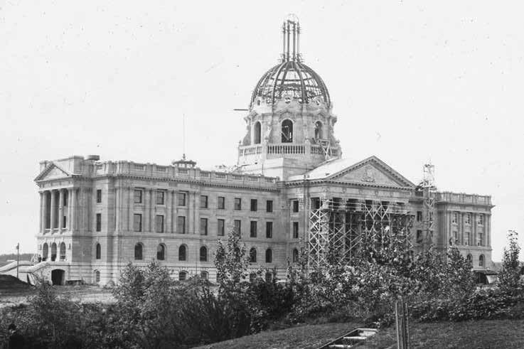
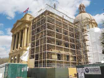
Designed by Provincial Architect Allan Merrick Jeffers in Beaux-Arts architectural style under the project name “Parliament Buildings,” construction of the Leg foundations began in 1907, with the granite cornerstone laid by the Governor General of Canada Lord Earl Grey on October 1, 1909 and the grand opening officiated by the Duke of Connaught on September 3, 1912, albeit without cladding on the major dome as reported only 34 days earlier in an Edmonton Journal [1] article titled “Who’ll Crown Parliament Building Ere Royalty Comes To Gaze
Upon It?” Regarding the cladding material to be used on the dome, the article stated, “Commissioner Chalmers had not ordered the copper skull top. Nobody had. …. The premier now worries to determine whether the Duke or the copper roof-skull will arrive first.” As it turned out, the Duke arrived first and terra cotta was eventually used to clad the major and minor domes.
The building structure consists of interior steel framing and thru-wall masonry loadbearing exterior walls constructed of an inner wythe of clay tile finished with plaster, an outer wythe of sandstone (except for the base which is granite), and clay brick infill. Measurements made on the exterior masonry wall at a ground floor level window revealed a wall thickness of 53 inches (1350 millimeters).
Except for the drums of the north portico freestanding columns, which are sandstone from Ohio, the sandstone used on the Leg is native to Alberta underlying a large portion of the southwestern portion of the province in what is known as the Paskapoo and Porcupine Hills Formations. At the time of construction of the Leg a number of sandstone quarries were in operation in the province; however, it is reported that the great majority, if not all, of the Alberta stone is believed to be Paskapoo sandstone from the Glenbow Quarry, which was located between Calgary and Cochrane on the north bank of the Bow River on what is now part of Glenbow Ranch Provincial Park. The Paskapoo Formation takes its name from the sandstone outcrops along the Blindman River (paskapiw means “He is blind” in Cree) [2].
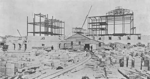
Stone storage and yard on west side of Legislature Building. (Provinical Archives of Alberta, A11027) .
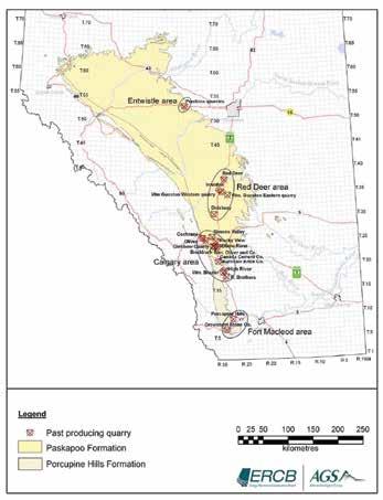
Paskapoo and Porcupine Hills Formations and past-producing quarries. (Figure 5, ERCB/AGS Open File Report 2010-01 [3].)
Although some sandstone finishing and sculpting work occurred at Glenbow Quarry it is believed that the great majority of the work was carried out on-site at the Leg.

On-site stone fabrication (1911). Allan Jeffers on the right. (Glenbow Museum Archives NA-1042-10).
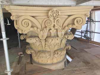
Based on his 1914 and 1915 travels on behalf of Canada Department of Mines to document building stone across the prairie provinces, in reference to the quality of Paskapoo sandstone William Arthur Parks reported [3] the following:
• “The average stone is not suitable for very exposed positions. Small pillars, copings, etc. are generally found to be seriously disintegrated after a few years.”
• “The stone should never be laid up on edge as it is prone to exfoliation.”
• “The average stone, however optimistic we may desire to be, is not really a first-class sandstone for monumental structures.”
However, that being said, the quality of Paskapoo sandstone is typically found to increase with depth, with greatly improved physical properties as the colour changes from yellow to buff to grey and finally to blue. Note that Parks [3] described “Glenbow-Cochrane” Paskapoo sandstone as “greyish yellow stone,” which the Leg has shown turns to “buff” as it weathers.
Sandstone cladding restoration project [2019-2023]
In keeping with Parks’ assessment, significant deterioration of Leg sandstone units has occurred over the past 100 years. Up-close review of the entire cladding was carried out from man lifts by the project prime consultant, Building Science Engineering Ltd. (BSE) and masonry/ stone restoration expert sub-consultant BBSTEK Design Ltd. in April and May 2016. This revealed thousands of deficiencies which included spalling, chipping, cracking,
exfoliation, weathering, old patches, coatings, voids, and deteriorated mortar joints. All deficiencies were identified, photographed, and marked on elevation drawings to allow for the preparation of comprehensive and accurate restoration documents in the future.
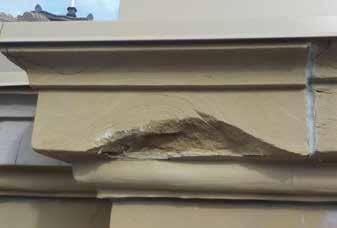
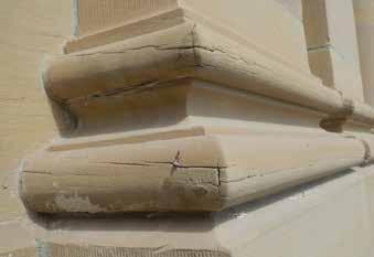
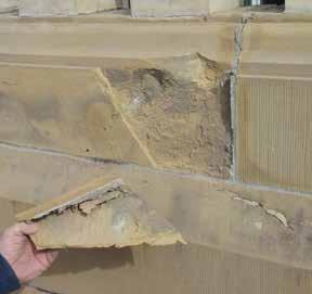
In addition to sandstone deficiencies that had occurred due to natural weathering, premature failures of past repairs resulting from the use of inappropriate materials and methodologies were also documented. Inappropriate repair materials included the use of nails, wood dowels, improper adhesives, stone repair mixes, mortar, coatings, and replacement materials such as precast concrete. Inappropriate repair methodologies included, but were not limited to, excessive and unnecessary removal of stone arises (stone edges) during repointing prep work as such loss of stone is irreversible, application of coatings that do not allow the stone to properly breathe (dry out) resulting in premature deterioration of stone substrate, inappropriate stone prep work for repair patches resulting in aesthetically displeasing patches that typically failed prematurely and installation of mortar within modillion head joints which could cause the projecting portion of the modillion to break off (which had happened at one location).
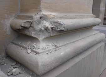
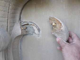
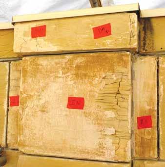
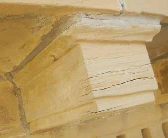
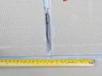


Replacement Paskapoo sandstone
It was agreed early on by the project restoration team, specifically the Province (Alberta Infrastructure), the prime consultant (BSE), and the prime contractor (Scorpio Masonry AB Inc.), that only Alberta (Paskapoo) sandstone would be used as replacement stone given the historical and architectural significance of the Leg and in keeping with conservation principles for historic structures [5]. As such the project team carried out an extensive provincewide search for a suitable and available source of Paskapoo sandstone, which included investigating the potential of past-producing quarries (including at Glenbow Ranch Provincial Park, Entwistle, Hard Luck Canyon, and Castor), more modern quarries and quarrying licenses (including Amico Stone supply quarry near Pincher Creek [Amico
Quarry] and Tay River) and gravel pits (in the event of excavation to bedrock), as well as investigating the possibility of using Paskapoo sandstone boulders uncovered during excavations for in-ground services in the Calgary area.
Boulders were initially used to facilitate a start to the project, however blocks from the Amico Quarry were used once the quarry restarted its operations. The Amico Quarry is located in the Porcupine Hills formation, which has been reported by as being up to 1220 meters thick with the upper portion being Paskapoo-equivalent [6].
Compressive strength, density, absorption, and freeze-thaw testing was initially and periodically carried out to evaluate the sandstone material obtained from boulders and Amico Quarry for compliance with the ASTM International standard for sandstone ASTM C616 [7]. The colour of the replacement stone was initially and periodically reviewed and approved by the project restoration team and Alberta Culture.
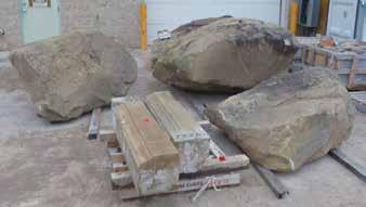
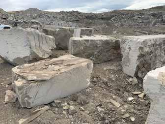
The fabrication process for Dutchman, indent, and full unit replacement stones included on-site measurement of original stones, creation of cut tickets, and fabrication of new stone units typically using state-of-the-art CNC stone processing machines which utilized saw blades and router bits in creating the stone profiles. The replacement stones invariably proved to be excellent replicates.


Sandstone repairs
From the information recorded during the 2016 upclose review of the stone cladding, comprehensive tender documents were prepared detailing the location and type of each and every deficiency, complete with cross-referenced photos, as well as each associated intervention. In total 22,230 interventions were carried out on sandstone units, which included the following types and number of repairs: 8,767 Dutchman, 344 indent, 338 full unit replacement (not including balusters), 323 baluster replacement, 4,641 plastic repair, 4,292 standard redress, 42 modillion redress, 1,310 surface grout, 428 injection grout, 1,740 coating removal, and 42 stitch/pin repairs. The entire stone cladding, with the exception of the major dome which had been fully repointed in 2013 as part of the domes recladding project, was also repointed using Type N mortar for horizontally projecting elements and a hybrid Type N/O mortar for the balance of the stonework. The quality of the stonework remediation was consistently of outstanding workmanship.
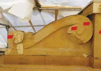
Sample of project drawings showing deficiencies and interventions.
Dutchman repairs of column base.
Below: South wing bull’s-eye window with sandstone Dutchman interventions marked (left), repair prep work underway (middle), and interventions and window repainting completed (right).
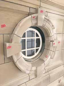
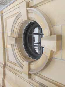

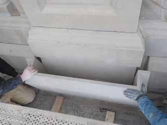
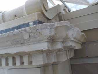
Water management
To extend the service life of horizontally projecting sandstone elements, metal, and membrane flashings (complete with granulated finish) were installed on top of the main roof parapet coping, raking cornices, main roof balustrade bottom rails, main roof cornice, main roof entablature architrave ledge, column capital projections, third floor window entablatures, and lower belt cornice.
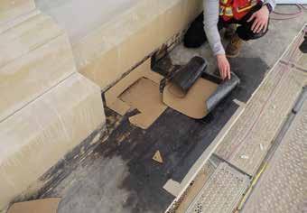

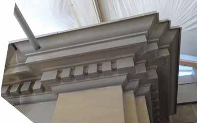
Window and balcony door restoration
Given the full-height scaffolding required for the sandstone cladding restoration work the Province decided to use the opportunity to also restore the original wood windows.
All of the second, third and fourth floor and minor dome double hung windows, south elevation fifth floor bull’seye windows, major dome fixed lite arched windows, and third and fourth floor fixed lite stained and leaded glass windows, were stripped to bare wood using chemical strippers, repaired as required (with minimal intervention in keeping with historical restoration principles), and repainted with linseed oil paint (Allback Holkham Green) to match what is believed to be the original coating material and dark green colour. Note that at some point in time sashes had been painted white and frames a lighter green. Furthermore, in the 1970s the single glazing in the double hung sashes had been replaced with double glazed sealed units. As part of the current restoration, these old, sealed units were replaced with new sealed units, complete with a low emissivity coating on the inner surface of the exterior lite, thermally resistant spacer bars, and an argon filled airspace. New weatherstripping was installed and all hardware was made good or replaced where required to match original. These upgrades resulted in more energy efficient fenestration and a more comfortable environment for occupants. Note that a small number of windows had original glazing, which was retained.
At the time of the earlier replacement of the original single lite glazing with the existing thicker double glazed sealed units the cross-sections of the sash rails and stiles were reduced (cut back), which combined with the heavier glass and setting blocks located away from the jambs, resulted in more pronounced downward deflection of upper sash meeting rails. Meeting rails with significant deflections were reinforced with small steel angles.
The painted wood balcony doors were stripped to bare wood, repaired as required (with minimal intervention) and repainted as per the restored windows. All hardware was made good or replaced where required to match original.
Entrance door restoration
The stained entrance doors at the north portico, east and west wing, and east loading dock were restored by stripping to bare wood, repairing as required and re-finishing with oil based stain and spar varnish top coat to match what is believed to be the original coating materials and colour.
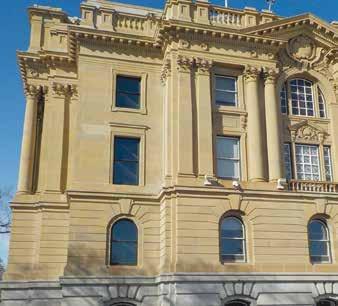

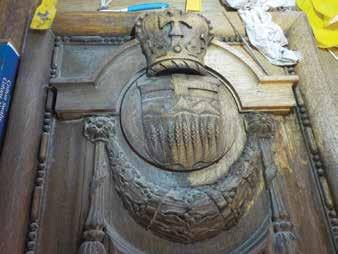
Summary of part one
Significant deterioration of the Leg sandstone cladding has occurred over the past 100 years. A total of 22,230 stone interventions were carried out to address these deficiencies which included past repairs that used inappropriate materials and methodologies. Metal and membrane flashings were installed over horizontally projecting stone elements to manage water. The wood windows and balcony doors were stripped, repaired, and repainted and the windows were reglazed. The main entrance doors were stripped, repaired, and re-stained. Cracked and displaced stones on the north portico were reinforced, repaired, and repositioned and displaced lower architrave stones were tied back to the structure.
Coming in part two
In the fall 2024 issue:
The north stair restoration work included removal of the existing deteriorated precast concrete raker beam structure and retrofit steel shoring and replacement of the severely corroded colonnade deck steel structure. A full-stair concrete slab and raker beam structure was cast-in-place and covered with waterproofing membrane. The granite tread and landing stones were repaired and re-laid complete with stainless steel dowels. The upper portion of the stair walls were rebuilt complete with waterproofing under the copings. A pilaster tie system was installed along the north corridor wall under the stair. Stainless steel handrails and column lighting were added. Steel grating catwalk was installed over the north portico soffit. n

References:
[1] ‘Edmonton Journal’ newspaper article, July 31, 1912, page 1.
[2] ‘Paskapoo Formation’, Wikipedia. https://en.wikipedia.org/wiki/Paskapoo_Formation
[3] ‘Building Stone in Alberta - ERCB/AGS Open File Report 2010-01’, C.S. Crocq, Energy Resources Conservation Board – Alberta Geological Survey, January 2010.
[4] “Report on the Building and Ornamental Stones of Canada, Vol. IV., Provinces of Manitoba, Saskatchewan and Alberta”, Canada Department of Mines – Mines Branch, by Wm. A. Parks, B.A., Ph.D., Ottawa Government Printing Bureau, 1916, No. 388.
[5] ‘Standards and Guidelines For The Conservation Of Historic Places In Canada’, A Federal, Provincial and Territorial Collaboration, Second Edition, Her Majesty the Queen in Right of Canada, 2010.
[6] ‘Paskapoo-Porcupine Hills Formation in Western Alberta: Synthesis of Regional Geology and Resource Potential’, A.P. Hamblin, ‘Geological Survey of Canada – Open File 4679’, 2004.
[7] ‘ASTM C616/C616M-15, Standard Specification for Quartz-Based Dimension Stone’, ASTM International, 100 Barr Harbor Drive, West Conshohocken, PA, United States.
[8] ‘Drawing 3.Q.20 Detail of Main Entrance Steps – Parliament Buildings’, The Government of the Province of Alberta, Department of Public Works, Engineering Department. A.M.Jeffers.Architect, June 1908.
[9] ‘Edmonton – Legislature Building – 2015 North Stair Structural Condition Update’, prepared by ‘Read Jones Christoffersen Consulting Engineers (RJC)’ and dated ‘September 4, 2015’.
[10] ‘Inspection Report No. S1’, prepared by ‘BPTECC Engineering’ and dated ‘October 15, 2021’.
PROJECT TEAM INCLUDED:
Client: Alberta Infrastructure
Prime Consultant: Building Science Engineering
Sub-Consultants:
Architectural: H2 Architecture (Burgess Bredo Architect)
Structural: BPTEC Engineering
Electrical: SMP Engineering
Prime Contractor: Scorpio Masonry
Window Restoration Contractor: E.T. Fraser Construction


COMMERCIAL ROOFING
FLAT
METAL
RUBBER
SLOPED
ASPHALT SHINGLES
TILE
WALL CLADDING
ALUMINUM COMPOSITE PANELS
VINYL CLADDING
WINDOWS
DOORS
FIBRE CEMENT
METAL PANELS
BUILDING ENVELOPE
RESTORATION
MULTI FAMILY PROJECTS
HISTORICAL RESTORATION
WATER INGRESS
WOOD ROT
VINYL DECK MEMBRANE
CONDO COMPLEXES
NEW CONSTRUCTION
LARGE INSURANCE CLAIMS
SPECIALTY PROJECTS
UNIQUE PROJECTS
LIQUID MEMBRANES
CUSTOM HOMES
INFRASTRUCTURE BUILDINGS
SERVICE DIVISION
REPAIRS AND MAINTENANCE
THERMAL IMAGING
MOISTURE DETECTION
LEAK INVESTIGATION
DRONES
METAL SHOP


who we are:
HIGHEST INDUSTRY STANDARDS
CONSCIENTIOUS CONTRACTOR
INDUSTRY LEADER
ELECTRIC VEHICLES
PROJECT SUMMARIES
SPECIALIZED INSTALLERS COMMITTED
FAIR AND CONSISTENT PRICING FUTURE PROOF DETAILED RELIABLE STAFF
RED SEAL JOURNEYMAN TECHS
INNOVATIVE CULTURE
COLLABORATE QUALITY
WORK WITH ENGINEERS WORK WITH ARCHITECTS UNDERSTAND YOUR NEEDS EXPERIENCED
SOCIALLY RESPONSIBLE CLEAR DATES CLEAR REPORTS
RESPECTFUL
CLIENT FIRST
EDUCATE ON SOLUTIONS INTEGRITY TRUSTED
ENVIRONMENT
GLOBAL CITIZENS
RESOURCEFUL


