4.2Risks of cavitation:...............................................................................................................................46
4.3Benefits of using low NPSH impeller:..................................................................................................46
4.4Consequences by using a low NPSH impeller:....................................................................................46
4.5Calculation of NPSHa..........................................................................................................................46
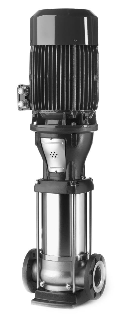
The vertical, single or multi-stage centrifugal pump series are designed for pumping clean, or lightly aggressive, watery mediums.
Suction and discharge of the pump are in-line, making the pump easy to install.
The hydraulic assembly is driven by an electric motor. All hydraulic parts of the pump are made of stainless steel.
The vertical, multi-stage centrifugal DPV pumps are produced by Duijvelaar pompen.
DPV2-4-610-15 B & 15 C
DPV25- 4060 B DPV 85B - 125
1.2Model key
Table 1: Model key Example DPVSF 85/3-1 B
DP VS F 85 /3 -1 B
LabelDP
Material/Construction VC
V
Product Label
Cast Iron pump foot and top bracket, hydraulics AISI 304
All wetted parts Stainless Steel 1.4301 / AISI 304 VS All wetted parts Stainless Steel 1.4401 / AISI 316
Connection F Round flange
85 Capacity in m3/h at Q.opt. (in m3/h)
/3 Number of stages
/3-1Number of stages of which one stage with reduced head
LLow NPSH impeller (model 2,4,6,10,15,25 en 40)
Vtwo stages of which one stage with reduced head and one impeller low NPSH
Wthree stages of which two stages with reduced head and one impeller low NPSH
B/CDesign version
1.3Operation
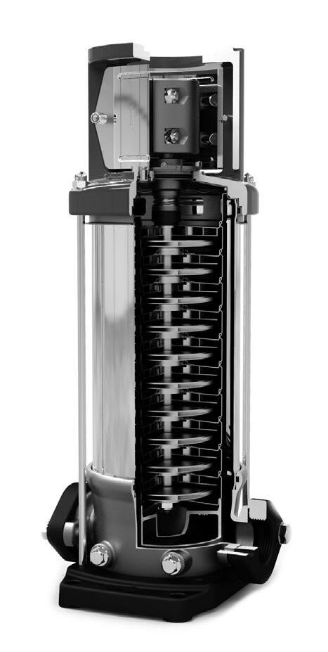
During centrifugal operation of the pump a negative pressure is created at the inlet of the impeller. This negative pressure enables the medium to enter the pump at the suction connection (A).
Every stage (B) consists of an impeller and diffuser. The passage of this stage determines the capacity of the pump. The diameter of the stages is related to the centrifugal forces and its “stage pressure”: the more stages, the more pressure.
This total capacity and raised pressure will be guided to the outside of the pump, between the pump stages and the outer sleeve (C) and the medium will leave the pump at the discharge connection (D).
Figure 1: DPVF 85
1.4Measuring, draining and venting
The pump is provided with plugs for measuring, draining and venting.
Connection (E) is meant to drain the inlet part of the pump. Or to measure the inlet / suction pressure using a G ¼ connection.
Connection (F) is meant to drain the outlet part of the pump. Or to measure the discharge pressure using a G ¼ connection.
Connections (G) are meant to vent the pump system when the pump is not in operation. Or to measure the discharge pressure of the pump using a G 3/8 connection.
1.5Working range
The working range is depending on the application and a combination of pressure and temperature. The overall working range of the pumps can be summarised as follows:
For minimum capacity at medium temperature of 68 oF, see below table 3. In case of higher medium temperatures, see table 4.
avitation etc. a minimum capacity has to be secured. The minimum capacity corresponds to al percentage of the optimum floTo prevent the pump from overheating, gathering gas, cw Qopt in relation to the temperature of the liquid pumped.
Table 3: Minimum capacity (Qmin) in 60Hz
Table 4: Minimum capacity vs.temperature (in % of Q optimum)
1.If the ambient temperature exceeds the above value or the motor is located more than 3280 ft above sea level, the motor cooling is less effective and could require an adapted motor power. See table 5: Motor load dep. sea level or amb. temp or please contact your supplier for more detailed advice.
2.Deviation in viscosity and/or density could require an adapted motor power. Please contact your supplier for more detailed advice. Density [lbs/ft3] 62-156 2 Cooling forced motor cooling 3
3.The free space above the motor cooling fan must be at least 1/4 of the diameter of the inlet of the cooling fan in order to have a sufficient flow of (cooling) air.
4.Pumps that are intended for 50 Hz operation, may not be connected to 60 Hz power supply.
1.5.2Ambient temperature and higher altitude
If the ambient temperature exceeds the above value, or if the motor is located more than 3280ft above sea level, the motor cooling is less effective and could require an adapted motor power. See below table for the increased percentage of the motor power or contact your supplier for more detailed advice.
Table 5: Increase of required motor power
1.7Pump bearing
Medium lubricated stage bearing Tungsten Carbide against Ceramic
Optional pump bearing Tuc/TuC
In case of severe applications or using conditions, such as hot water, boiler feed (max 284°F) or when the pump experiences un avoidable dry running for a short time. The standard ceramic bearing material can be replaced / exchanged by a more resistant TuC/TuC bearing material.
Due to the specific material characteristics of Tungsten Carbide, the TuC/TuC material is even more resistant for the above mentioned severe conditions and will enhance the durability and lifecycle of the pump.
When combining the use of the optional TuC/TuC bearing material and the optional low NPSH kit, the pump can be made even more suitable for the above mentioned severe applications or using conditions.
1.6Basic material variants
Table 6: Basic material variants
1.44041.4408FPM VC 2-60 & 1251.4301JS1030EPDM
VC 851.4301JL1040EPDM
The optional combinations TuC/TuC bearing material and low NPSH kit are available for the vertical pump models DPVCF 2, 4, 6, 10, 15, 25 and 40.
Up to now only the optional TuC/TuC bearing material is available for the larger pump models DPVCF 25, 40, 60, 85 and 125.
For other possible pump options or features, please contact our sales department.
1.8Modular selection
To suit almost every application the pump is assembled out of modules which can be selected depending on the required working range. Basic modules are:
• Basic pump model, which defines the capacity, pressure and basic material. Temperature range -4 up to 284 °F, with the exception of the DPV 125 this pump can be used upto 248 °F.
• Connections, which define the suction and discharge connection as well as the base plate.
• Sealings, which define the elastomers, the mechanical seal and the shaft seal type.
• Electric motor, which defines all requirements of the motor such as motor size, power, voltage, frequency and all possible motor accessories.
1.9Approvals
CE Conformity with European Safety Directive
NSF Drinking water approval
2Performance characteristics
2.1Performance range
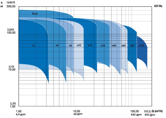
2.2Performance curve details
The performance diagrams give a global overview of all the pump models the shaded models are mentioned in this documentation. Detailed characteristics are given for each model showing the hydraulic efficiency, NPSHreq, and shaft power as well.
The performance of the pump depends on the number of stages. As per example:
DPV 4/2 Bmodel DPV 4 B2 stages with 2 full head impellers
DPV 85/4-1 Bmodel DPV 85 B4 stages with 3 full head impellers and 1 reduced impeller
The detailed performance curves are in accordance with ISO 9906: 2012 (Grade 3B).
The motors used for the measurements are calibrated motors with a specific rotational speed. Therefore the performance data, like Q/H, efficiency and shaft power used for published curves are converted to the average speed per motor power. To refine this data the published data has to be corrected accordingly.
The published curves and data mentioned on the pump is based on a rotational speed of 3500 rpm for 2P motors.
The maximum required power for the hydraulics to cover the curve (run-out performance) is mentioned on the name plate of the pump. This power
Figure 2: Performance range DPV(C/S) B/C 60 Hz
corresponds to above mentioned rated speeds. In the pump curves also the required hydraulic power on a specific duty point can be determined.
In case of using a motor with another rated speed as mentioned in the table, please recalculate the required power according the formula in figure 3.
To cover the required hydraulic power all pumps are pre-equipped with a support flange to fit the specific rated motor power, see pump data. In some cases on this rated power it will be necessary to use a part of the common motor service factor*) to cover the “runout performance” of the pump.
In those cases to a maximum of 15% on the rated power will be required. As the pumps apply to ISO9906:2012 Grade 3B tolerances we recommend to use motors which have a 1.25 service factor.
*) The service factor is the allowed exceeded power of the motor rated power which may be used incidentally. Per motor brand this value can differ and therefore needs to be checked before installation.
The characteristics given are based on:
• De-aerated water at a temperature of 68 °F
• Density of 62 lbs/ft3
• Kinematic viscosity of 1 cSt
To prevent the pump from overheating, gathering gas, cavitation etc.a minimum capacity has to be secured. The minimum capacity corresponds to a percentage of the optimum flow Qopt in relation to the temperature of the liquid pumped.
2.3Minimum efficiency index
The minimum energy-efficiency level according to the ErP regulations for water pumps is specified by the minimum efficiency index MEI. A high MEI value indicates a high efficiency of the determined pump. From 1 January 2015 on the minimum efficiency index (MEI) for standardised water pumps is ≥ 0.4.
For the DPV pump ranges the following values are applicable:
Table 7: Minimum efficiency index
Pump range Minimum Efficiency index
DPV 2BMEI ≥ 0.70
DPV 4BMEI ≥ 0.70
DPV 6BMEI ≥ 0.70
DPV 10BMEI ≥ 0.70
DPV 15CMEI ≥ 0.70
DPV 25BMEI ≥ 0.70
DPV 40BMEI ≥ 0.70
DPV 60BMEI ≥ 0.70
DPV 85BMEI ≥ 0.60
DPV 125BMEI ≥ 0.70
DPLHS 6MEI ≥ 0.60
2.4Performance with variable frequency drive
The minimum frequency of the motor should be limited to 30 Hz. When the rotational speed exceeds the nominal speed of the motor, make sure that the power output of the motor is suitable to drive the corresponding pump model.
The performance of the pump differs from the fixed speed performance according to the recalculation scheme.
2.5How to read the values from the curves
To find the required hydraulic information from the published curves, it is important to know the application in which the pump has to be installed. There are two main distinction to be made:
AFlow determined (like booster sets and cleaning) Opening taps
How to read the motor power. The required motor power can be read in the curve ’Power input’.
Attention: the power value as mentioned in this curve is the required power per stage. For some pump types there are two lines in the curve this is related to the full impeller or reduced impeller [-1].
Figure 3: Performance characteristics
Figure 4: How to read the values from the curves
O Calculated duty point
Actual hydraulic performance
A Flow determined
B Pressure determined
3227/04072008
Pump size / no of stages.
Installed motor power
Capacity @ Pressure
NPSH (m)
Hydraulic efficiency (%)
Required power (P2)
3Curves and dimensions
3.1Hydraulic performance curve DPV 2 B - 60Hz -2 pole (3500 rpm)
Table 9: Standard motor power - Dimensions and weights based on typical NEMA motors, not supplied by DP Pumps # Pump type optional with decreased motor power
Table 10: Decreased motor power: Dimensions and weights based on typical NEMA motors, not supplied by DP Pumps
Table 19: Decreased motor power: Dimensions and weights are based on typical NEMA motors, not supplied by DP Pumps
10/13 #215TC1512.9379.62510.00045.0628.5614836945.0628.56133354 10/15215TC1512.9379.62510.00047.1530.6515237347.1530.65137358 Model Frame size Power req.
* Motor dimensions and masses are based on typical NEMA motors, not supplied by DP Pumps
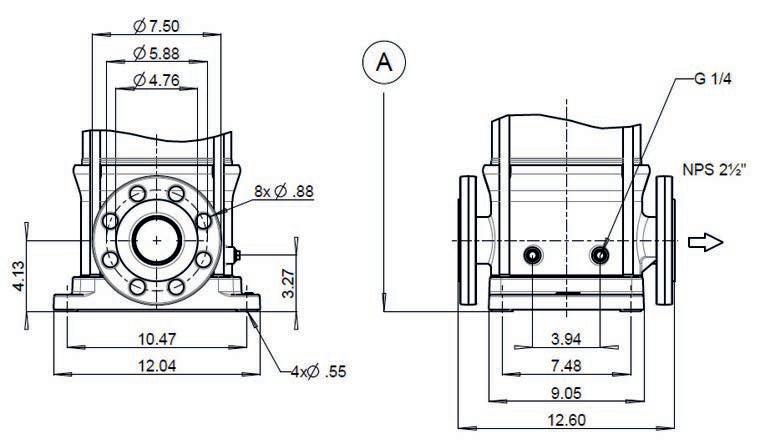
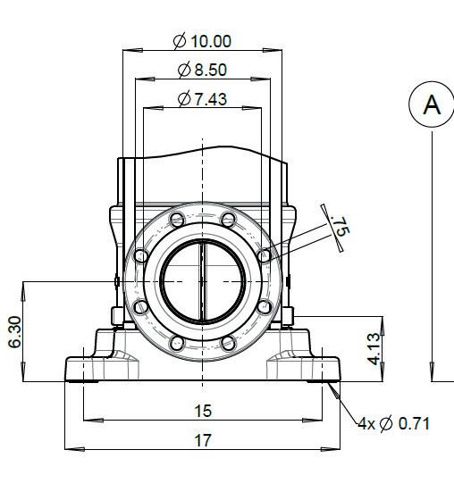
Table 36: Layout and connections
DPVLHS
Norm: ASME B16.1
Size: 4” (NPS 4)
Pressure Class 600# 5/4”(NPS 5/4”)
Table 37: Dimensions and weights
6-10015215TC12.9379.62510.00039.1822.68122343
6-12015215TC12.9379.62510.00040.3623.86135356
6-14020256TC12.9379.62510.00042.1725.67153373
* Motor dimensions and masses are based on typical NEMA motors, not supplied by DP Pumps Model Frame
4Low NPSH impeller
4.1General
Low NPSH impeller
For the pump type series DPV(S/C)(F) 2, 4, 6, 10 and 15 it is now possible to have a low NPSH solution as option. This solution based on a new designed low NPSH impeller and modified stage casing the NPSH curve of the pump will have much better values throughout its raster. This can prevent cavitation in the pump in case of critical inlet conditions. Cavitation is the process of forming vapour-filled cavities within the liquid in areas where the available pressure has been reduced below a certain critical value. This also happens in case the pressure drops below the vapour pressure of the liquid. When the pressure raises these cavities will implode to become fluid again. These implosions generate pressure waves which are transmitted to the surfaces of the hydraulic pump parts and can damage the material. This phenomenon is called incipient cavitation and is characterized by a metallic noise produced by the hammering on the material.
4.2Risks of cavitation:
Reduced lifetime of the pump due to damaged parts and unbalanced hydraulics. Excessive wear of pump parts or motor bearings. Insufficient cooling and/or lubrication of the mechanical seal and pump bearing.
4.3Benefits of using low NPSH impeller:
More suitable in critical inlet conditions. Easy adaption to non-optimized application parameters. The suction lift (Hp) can be less critical (e.g. the frame height of the de-aerating tank in case of boiler feed can be reduced)
4.4Consequences by using a low NPSH impeller:
No change in pump height or connection.
Slight adjustments on the performance curve, see curves as published on pages 48 to 56.
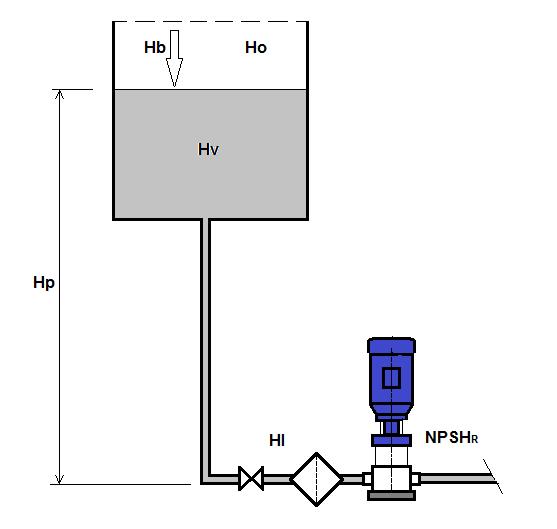
4.5Calculation of NPSHa
Calculation NPSHa > NPSHr + 1.64
Check if cavitation can be expected.
Hb + Ho + Hp - HV - Hi > NPSHr + 1.64
Hb = barometric pressure in ft
Ho = over pressure (in case of closed tank) in ft
Hp = suction lift in ft
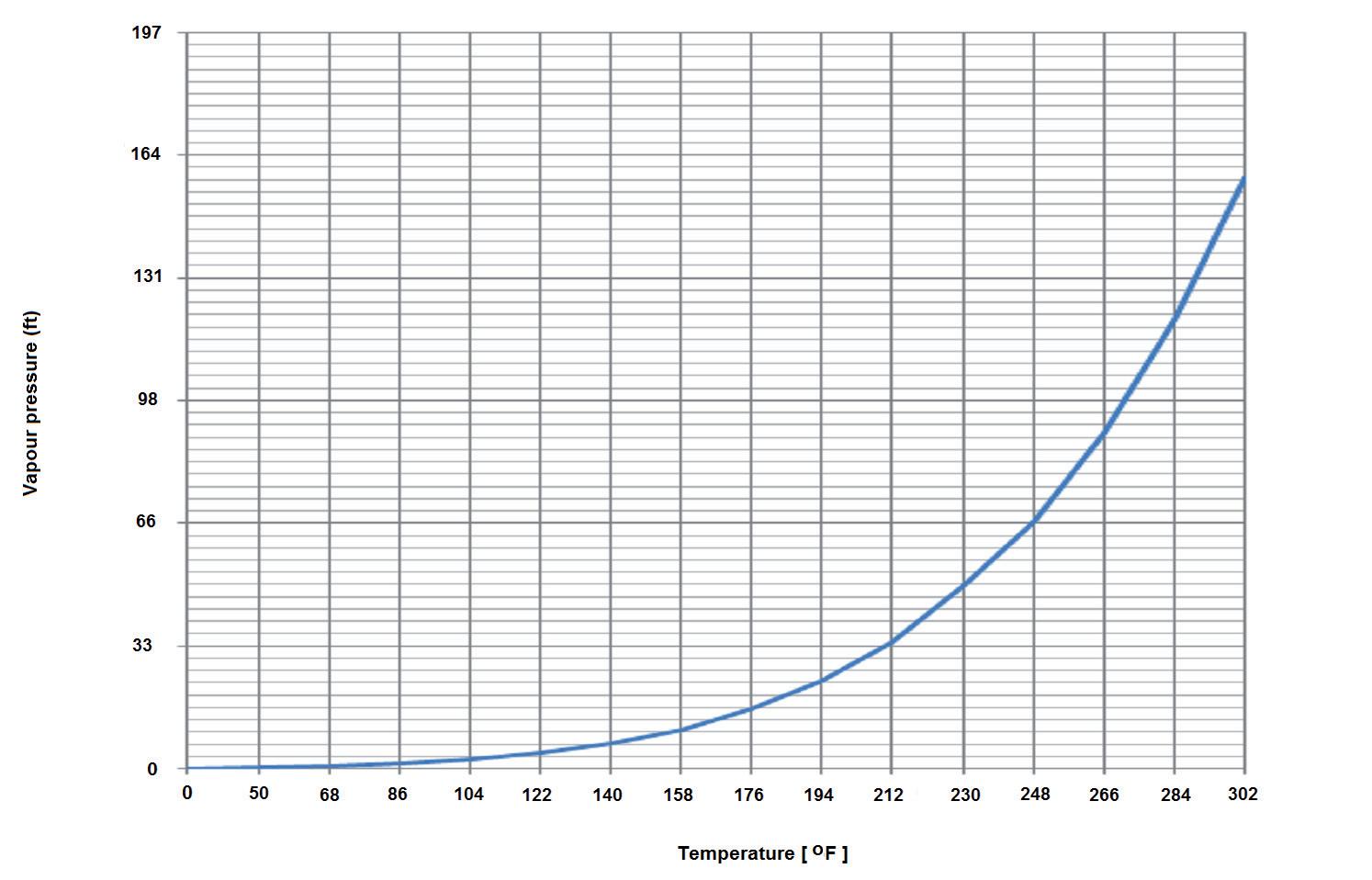
Hv =- vapour pressure in ft
Hl = friction loss in pipe work and accessories in ft
NPSHr = net positive suction head of the pump safety factor = 1.64 ft
Table 38: Calculation NPSHa
Atmosferic pressure + 33.8 ft
Overpressure in degassing tank + …… ft
Positive height of degassing tank or vessel + ……. ft
Vapour pressure of feed water (see table)in degassing tank in case of boiler feed - ……. ft
Loss of pressure in suction piping and strainer - ……. ft
Safety factor - 1.64 ft
NPSHr at duty point (see pumpcurve) - ……. ft
Minimal positive pressure x ft
If 'x' is positive there is no cavitation to be expected
If 'x' is negative cavitation can be expected, to avoid this the low NPSH impeller could solve this problem. Otherwise one of the other values can be changed so the outcome will be positive.
Figure 25: Grafieken DPV(C/S) 40 B - 60Hz - 2 pole
20211156
5Seals
5.1Mechanical seal option specifications
15RMG12-G606U3 U3 X4 GG
22H7N Q1 A X4 GG
404MC Q1 Q1 E GG
414MC Q1 A E GG
TuCTuCHNBRPN25(PN16)-20/+120(140)°CHNBR
SiCCaHNBRPN40(PN25)-20/+120(140)°CHNBRHP/HT ●
SiCSiCEPDMPN40(PN25)-20/+120(140)°CEPDMHP/HT
SiCCaEPDMPN40(PN25)-20/+120(140)°CEPDMHP/HT
424MC Q1 Q1 V GG SiCSiCFPMPN40(PN25)-20/+120(140)°CFPM HP/HT
434MC Q1 A V GG SiCCaFPMPN40(PN25)-20/+120(140)°CFPM HP/HT ●
50RMG12-G6A Q7 E GG
51eRMG12-G6A Q7 E GG Y10
52eRMG12-G6A Q7 V GG Y10
CaeSiCEPDMPN25(PN18)-20/+120(140)°CEPDM 559236 ●●
CaeSiCEPDMPN25(PN18)-20/+120(140)°CEPDM
CaeSiCFPMPN25(PN16)-20/+120(140)°CFPM ● 53eMG12-G6B Q7 E GG Y10 WACaeSiCEPDMPN25-20/+100°CEPDM
54MG12-G6B Q7 E GG WA
55RMG12-G6B Q7 V GG
56eRMG12-G6B Q7 V GG Y10
57MG1-G6B Q7 E GG WA
CaeSiCEPDMPN25-20/+100°CEPDM
CaeSiCFPMPN25-20/+120°CFPM
CaeSiCFPMPN25-20/+120°CFPM
CaeSiCEPDMPN25-20/+100°C
58eMG12-G6Q7 Q7 E GG Y10 WAeSiCeSiCEPDMPN18-20/+100°CEPDM
59MG12-G6Q7 Q7 E GG WAeSiCeSiCEPDMPN18-20/+100°CEPDM
60RMG12-G6Q7 Q7 V GG eSiCeSiCFPMPN18-20/+120°CFPM
61eRMG12-G6Q7 Q7 V GG Y10eSiCeSiCFPMPN18-20/+120°CFPM
65eRMG12-G6U3 U3 V GG Y10TuCTuCFPMPN18-20/+120°CFPM
66eMG12-G6Q7 Q7 V GG Y10eSiCeSiCFPMPN20-20/+60°CFPM ●
ATTENTION
Seal dimensions according to EN24960
5.1.1Seal material description
Seal part
Code Description
Face materialsynthetic carbonA
Carbon graphite resin impregnated carbides Q1
Carbon graphite antimony impregnated B
SiC, silicon carbide, sintered U3
Tungsten carbide, NiCrMo-binder
Elastomer
Spring material
Construction material
Ethylene propylene rubber (EPDM)
Fluorcarbon rubber (FPM) X4
Hydrogenated Nitrile-rubber (HNBR)
CrNiMo steel (1.4571)
CrNiMo steel (1.4571)
6Motors
6.1General
For the NEMA flanged bare shaft pumps specific C-faced NEMA motors can be mounted. For these motors the following technical specification regarding the bearings needs to be considered.
Fixed driven-end re-enforced bearing according the following table
0.556C6203 2Z-C3supplier standard
0.7556C6203 2Z-C3supplier standard
1 143TC6204 2Z-C3supplier standard
1.5143TC6204 2Z-C3supplier standard
2 145TC6305 2Z-C3supplier standard
3 182TC6305 2Z-C3supplier standard
5 184TC6306 2Z-C3supplier standard
7.5213TC7309supplier standard
10215TC7309supplier standard
15215TC7309supplier standard
20256TC7311supplier standard
25284TSC7311supplier standard
30286TSC7312supplier standard
40324TSC7312supplier standard
50326TSC7313supplier standard
60364TSC6312supplier standard
7Materials
7.1Parts overview
7.1.1Part list
Taper piece
Coupling from 7.5hp
Coupling up to 5hp
Base plate
Base plate
Screwed plugs (vent) and drain
Tie bolt
Class 25JS1030
Safety device Nord-lock
2-15 B
Standard Option
7.1.2Materials conversion
JL 1040A48:40B Cast iron GJL-250 EN 1561 JS1030 Cast iron GJS-400 EN 1563
1.Note: The indication of the material designations to ASTM / AISI is not binding
8Medium
handled
8.1Medium handled
duijvelaar pompen
Kalkovenweg 13
2401 LJ Alphen aan den Rijn
The Netherlands
t +31 172 48 83 88
dp@dp.nl www.dp.nl
01/2025
97004480 J
Subject to modifications. Digital alteration, publication or distribution of the content of this document without prior notice is strictly prohibited. Permission for use, copying and distribution of this document as published by DP-Pumps is granted on the condition that no part of the document is used for information or commercial purposes outside of the DP-Pumps organisation or one of its recognised dealerships.