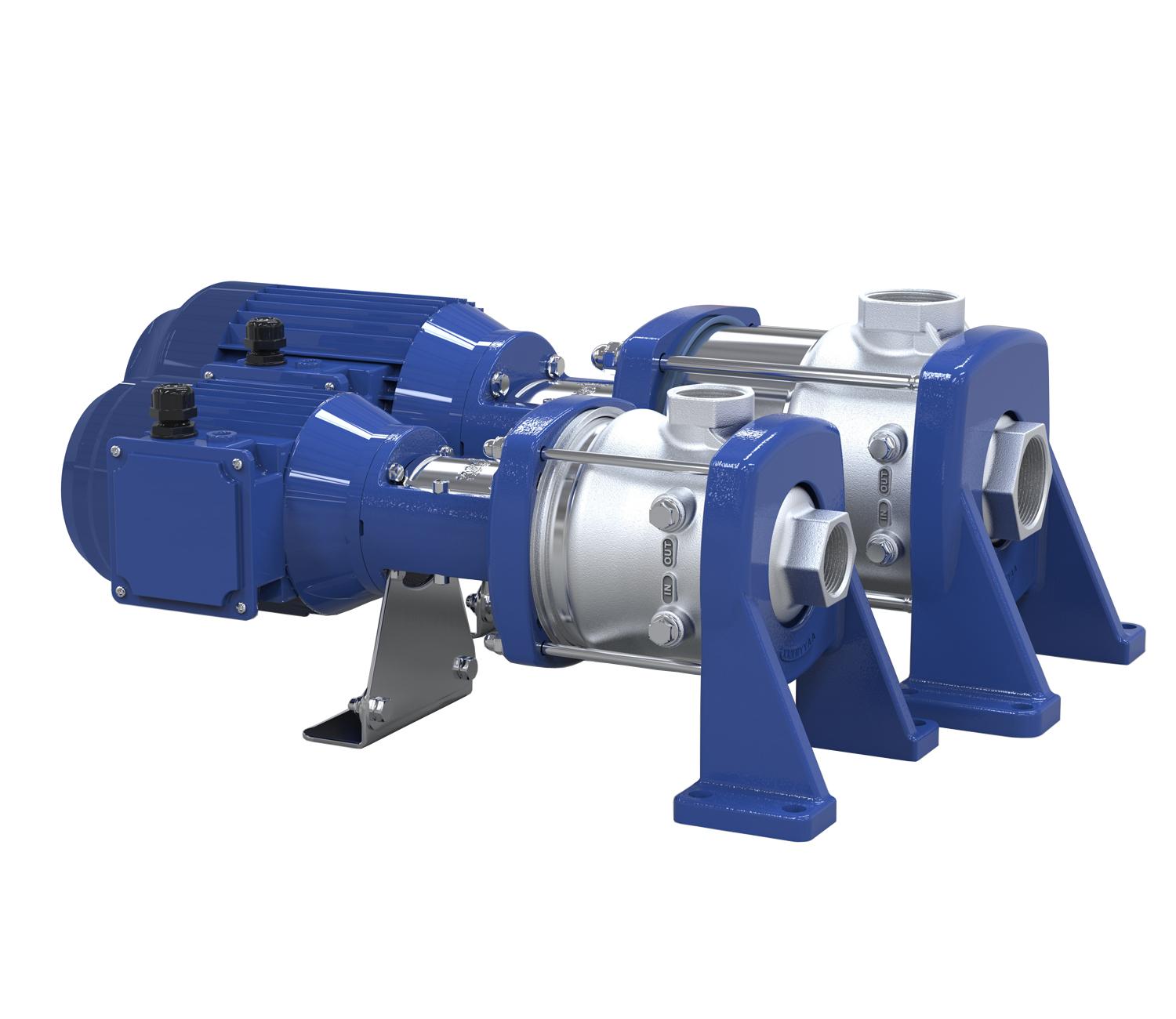
Multistage Horizontal High-pressure Centrifugal Pump

Type Series Booklet DPH(S)I
Type Series Booklet DPH(S)I
Legal information/Copyright
All rights reserved. The contents provided herein must neither be distributed, copied, reproduced, edited or processed for any other purpose, nor otherwise transmitted, published or made available to a third party without the manufacturer's express written consent. Subject to technical modification without prior notice. © Duijvelaar Pompen, Alphen aan den Rijn, Netherlands 17/02/2022
Contents 3 Contents High-pressure Pumps 5 Multistage Horizontal High-pressure Centrifugal Pump 5 DPH(S)I 5 Main applications 5 Fluids handled 5 Operating data ............................................................................................................................................................... 5 Design details 5 Designation 6 Materials 8 Coating and preservation 8 Product benefits 9 Product information 9 Product information as per Regulation No. 1907/2006 (REACH) 9 Certifications 9 Acceptance tests and warranty ..................................................................................................................................... 9 Selection information 10 Impeller for lower NPSH values ............................................................................................................................. 10 Information about the characteristic curve 11 Fluid handled 12 Overview of product features / selection tables 13 Overview of fluids handled 13 Shaft seal 16 Technical data 17 Motors 17 Selection chart 19 DPH(S)I, 2P 50 Hz 19 DPH(S)I, 4P 50 Hz 20 DPH(S)I, 2P 60 Hz .................................................................................................................................................... 21 DPH(S)I, 4P 60 Hz 22 Characteristic curves..................................................................................................................................................... 23 DPH(S)I, 2B, 2P 50 Hz 24 DPH(S)I, 2-LB, 2P 50 Hz 25 DPH(S)I, 4B, 2P 50 Hz 26 DPH(S)I, 4-LB, 2P 50 Hz 27 DPH(S)I, 6B, 2P 50 Hz 28 DPH(S)I, 6-LB, 2P 50 Hz........................................................................................................................................... 29 DPH(S)I, 10B, 2P 50 Hz 30 DPH(S)I, 10-LB, 2P 50 Hz 31 DPH(S)I, 15C, 2P 50 Hz 32 DPH(S)I, 15-LC, 2P 50 Hz 33 DPH(S)I, 10B, 4P 50 Hz 34 DPH(S)I, 10-LB, 4P 50 Hz......................................................................................................................................... 35 DPH(S)I, 15C, 4P 50 Hz 36 DPH(S)I, 15-LC, 4P 50 Hz 37 DPH(S)I, 2B, 2P 60 Hz 38 DPH(S)I, 2-LB, 2P 60 Hz 39 DPH(S)I, 4B, 2P 60 Hz 40 DPH(S)I, 4-LB, 2P 60 Hz........................................................................................................................................... 41 DPH(S)I, 6B, 2P 60 Hz 42 DPH(S)I, 6-LB, 2P 60 Hz 43 DPH(S)I, 10B, 2P 60 Hz 44 DPH(S)I, 10-LB, 2P 60 Hz 45 DPH(S)I, 15C, 2P 60 Hz 46 DPH(S)I, 15-LC, 2P 60 Hz......................................................................................................................................... 47 DPH(S)I, 10B, 4P 60 Hz 48 DPH(S)I, 10-LB, 4P 60 Hz 49
Contents 4 DPH(S)I, 15C, 4P 60 Hz 50 DPH(S)I, 15-LC, 4P 60 Hz 51 Installation types 52 Dimensions and connections 53 DPH(S)I 2B, 2P 50 Hz 53 DPH(S)I 2B, 2P 60 Hz 54 DPH(S)I 4B, 2P 50 Hz............................................................................................................................................... 55 DPH(S)I 4B, 2P 60 Hz 56 DPH(S)I 6B, 2P 50 Hz 57 DPH(S)I 6B, 2P 60 Hz 58 DPH(S)I 10B, 4P 50 Hz 59 DPH(S)I 10B, 4P 60 Hz 60 DPH(S)I 10B, 2P 50 Hz............................................................................................................................................. 61 DPH(S)I 10B, 2P 60 Hz 62 DPH(S)I 15C, 4P 50 Hz 63 DPH(S)I 15C, 4P 60 Hz 64 DPH(S)I 15C, 2P 50 Hz 65 DPH(S)I 15C, 2P 60 Hz 66 Scope of supply 66 General assembly drawing with list of components 67 DPH(S)I 2/4/6B 67 DPH(S)I 10 B 68 DPH(S)I 15 C ............................................................................................................................................................ 70
High-pressure Pumps
Multistage Horizontal High-pressure Centrifugal Pump
DPH(S)I
19068612107
Main applications
▪ Spray irrigation systems
▪ General irrigation systems
▪ Washing plants
▪ Fire-fighting systems
▪ Pressure boosting
▪ Industrial plants
▪ Water supply systems
▪ Heating, ventilation and air-conditioning systems
▪ Marine applications
Fluids handled
▪ Hot water
▪ Clear water
▪ Condensate
▪ Cooling water
▪ Fire-fighting water
▪ Oil
▪ Cleaning agents
▪ And others
Operating data
Table 1: Operating properties
High-pressure Pumps
Multistage Horizontal High-pressure Centrifugal Pump
Design details
Design
▪ High-pressure pump
▪ Maximum pressure class PN 25
▪ Centrifugal pump
▪ Single-stage or multistage
Installation
▪ Horizontal installation
Drive
▪ Surface-cooled DP squirrel-cage motor
▪ Thermal class F to IEC 34-1
▪ Efficiency class IE3 to IEC 60034-30 (≥ 0.75 kW)
▪ Enclosure IP55
▪ Frequency 50 Hz/60 Hz
Optional:
▪ Harting connector, type HAN 10E
Automation
Automation options:
▪ PumpDrive
▪ PumpMeter
Shaft seal
▪ Uncooled maintenance-free mechanical seal
– Fixed mechanical seal
– Easy Access mechanical seal
– Cartridge seal
Bearings
▪ Tungsten carbide plain bearings at the hydraulic rotor
5 DPH(S)I
Characteristic Value Flow rate Q [m3/h] ≤ 27 Head H [m] ≤ 195 Fluid temperature T [°C] ≥ -20 ≤ +140 Operating pressure p [bar] ≤ 25
High-pressure Pumps
Multistage Horizontal High-pressure Centrifugal Pump
6 DPH(S)I Designation
Position 1 2 3 4 5 6 7 8 9 10 11 12 13 14 15 16 17 18 19 20 21 22 23 24 D P H S I 1 5 / 0 4 - B 4 S 1 3 F E 1 1 2 B 7 U See name plate and data sheet See data sheet
Position Code Description 1-2 Pump type DP DP 3-4 Version H Cast steel (1.4308) HS Cast steel (1.4408) 5 Connection type I Internal thread 6-7 Size 02 2 15 15 9-10 Number of stages 01 1 14 14 11 Number of stages with special impeller1) No stage with a special impeller L First stage with a special impeller for lower NPSH values 12 Product generation B DP from 2010 C DP from 2021 13 Connection standard 4 Internal thread (EN ISO 228-1) 14 Material variant S Cast steel (1.4408 - 1.4408 - EN-GJS-400-15) 15-16 Seal code 11 BQ1EGG 12 BQ1VGG 13 Q1BEGG 14 Q1BVGG 15 U3U3X4GG 16 U3U3VGG 18 U3BEGG 23 Q1BEGG 24 Q1Q1VGG 28 Q1Q1X4GG 29 Q1Q1EGG 17 Mechanical seal design F Fixed mechanical seal E Easy Access mechanical seal C Cartridge seal 18 Drive E Without motor - Standard IEC 19-21 Motor size 056 NEMA 56C 071 IEC 71 080 IEC 80 090 IEC 90 100 IEC 100 1 Blank
Table 2: Designation example
Table 3: Designation key
High-pressure Pumps
Multistage Horizontal High-pressure Centrifugal Pump
0.37/0.55 kW, without IE classification
230 V, single-phase AC motor
230/400 V - IE3
400/690 V - IE3
- IE4/IE5
400/690 V - IE4/IE5
7 DPH(S)I Position Code Description 19-21 112 IEC 112 132 IEC 132 143 NEMA 143TC 145 NEMA 145TC 160 IEC 160 180 IEC 180 182 NEMA 182TC 184 NEMA 184TC 200 IEC 200 215 NEMA 215TC 225 IEC 225 256 NEMA 256TC 284 NEMA 284TC 286 NEMA 286TC 324 NEMA 324TC 326 NEMA326TC 364 NEMA 364TC 22 Pressure class A PN16 / PN25 B PN25 23 Frequency, number of motor poles 5 50 Hz, 2-pole 6 60 Hz, 2-pole 7 50 Hz, 4-pole 8 60 Hz, 4-pole 24 Motor specification
A
U
V
W
X
M
230/400 V
Table 4: Overview of available materials
High-pressure Pumps
Multistage Horizontal High-pressure Centrifugal Pump
Table 5: Comparison of materials
Coating and preservation
Table 6: Coating of pump components Component Coating Drive lantern Cataphoretic coating Pump foot Powder coating
2 Sizes 2B, 4B, 6B, 10B, 15C (≤ 4 kW)
3 Sizes 2B, 4B, 6B, 10B, 15C (≥ 5.5 kW)
8 DPH(S)I Materials
Part No. Description Variant H HS 10-6 Pump shroud 1.4301 1.4404 101 Pump casing 1.4408 1.4408 108 Stage casing 1.4301 1.4404 160 Discharge cover 1.4301 1.4404 210 Shaft 1.4057 1.4460 230 Impeller 1.4301 1.4404 341 Drive lantern EN-GJL-2502) / EN-GJS-400-153) 412 O-ring EPDM-WRc / ACS FPM / HNBR 525 Spacer sleeve 1.4301 1.4401 529 Bearing sleeve Tungsten carbide / aluminium oxide 89-11 Retaining bracket 1.4301 890 Baseplate EN-GJS-400-15 905 Tie bolt 1.4057 920 Nut 1.4301 1.4404 932 Circlip 1.4571
EN ASTM EN-GJL-250 A48 Class 35 B EN-GJS-400-15 A536 Gr. 60-40-18 1.4057 SS 431 1.4301 SS 304 1.4308 Gr. CF8 1.4404 SS 316L 1.4408 Gr. CF8M 1.4460 SS 329 1.4571 SS 316Ti
Product benefits
▪ Reliable: product-lubricated plain bearings made of tungsten carbide, cast pump foot, torsion-resistant pump shroud and confined O-rings
▪ Long service life: corrosion-resistant hydraulic components made of stainless steel
▪ Easy to service: can be fitted with any standardised mechanical seal (to EN 12756)
▪ Easy to install underneath other machinery due to horizontal installation
Certifications
Table 7: Overview
High-pressure Pumps
Multistage Horizontal High-pressure Centrifugal Pump
Product information
Product information as per Regulation No. 1907/2006 (REACH)
For information as per chemicals Regulation (EC) No. 1907/2006 (REACH), see http://www.dp.nl/reach
Label Effective in: Comment United Kingdom Approved in accordance with the UK drinking water regulation
Acceptance tests and warranty
▪ Pressure test – to EN 809
▪ Leak test
with water
▪ Materials testing
Certificate of compliance with the order (corresponds to EN 10204)
In the certificate of compliance with the order the manufacturer confirms by way of an informal report without specifying test results that the delivery complies with the stipulations of the purchase order.
– Test report 2.2 on request
▪ Final inspection – Inspection certificate 3.1 to EN 10204 on request
▪ Hydraulic test
The duty point of each pump is guaranteed to ISO 9906:2012 Grade 3B.
This test is always carried out using the original motor. The NPSH and the suction lift are not measured (3.2 certificate available).
▪ Warranties
Warranties are given within the scope of the valid terms and conditions of sale and delivery.
9 DPH(S)I
–
–
Selection information
Impeller for lower NPSH values
An impeller for lower NPSH values is available for sizes 2, 4, 6, 10 and 15. This type of impeller ensures that the pump’s NPSH curve is significantly improved. The solution is based on a newly developed impeller for lower NPSH values and a modified stage casing. Cavitation inside the pump can hence be prevented in the case of critical inlet conditions.
Risks of cavitation:
▪ Reduced lifetime of the pump due to damaged parts and unbalanced hydraulic system
▪ Excessive wear of pump parts or motor bearings
▪ Insufficient cooling and/or lubrication of the mechanical seal and pump bearing
Benefits of using impellers for lower NPSH values:
▪ More suitable in critical inlet conditions
▪ Easy adaptation to non-optimised application parameters
▪ The suction lift (Hp) is less crucial (the frame height of the degassing tank used in boiler feeding can be reduced).
Consequences of using impellers for lower NPSH values:
▪ No need to change pump installation heights or pump nozzles
▪ Minor adjustments to the characteristic curve
Fig. 1: Calculating the NPSHA
NPSHA NPSH system value at operating point
NPSHR NPSH pump value at operating point (see characteristic curve of the pump)
Hb Atmospheric pressure [mWc]
Ho Positive pressure (with tank closed) [mWc]
Hp Suction lift [mWc]
Hv Vaporisation pressure [mWc] (see water vaporisation pressure diagram)
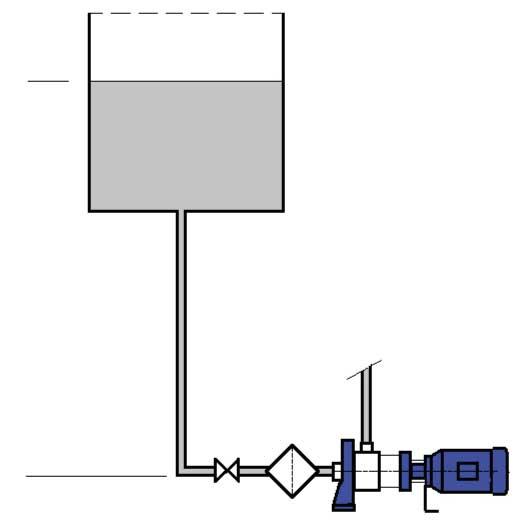
Hl Friction losses in pipes and accessories [mWc]
Hz Safety margin (min. 0,5 m)
x Minimum pressure
Result:
If the minimum pressure (x) is positive, there is no risk of cavitation. If the minimum pressure (x) is negative, there is a risk of cavitation which can be avoided by using an impeller for lower NPSH values. Another option is to change one of the other values so that the value becomes positive.
Example:
▪ Boiler feed water: 105 °C
▪ Positive height of tank: 2 m
▪ Positive pressure in tank: 3 mWc
▪ Flow rate: 5 m³/h
▪ Head: 100 m (10 bar)
▪ Size selected: 4
High-pressure Pumps Multistage Horizontal High-pressure Centrifugal Pump 10 DPH(S)I
H p Hb H o H v H NPSHR NPSHA ≥ NPSHR + H z NPSHA = Hb+ H o + H p - H v - Hl = Hb+ H o + H p - H v - Hl - NPSHR - H z ≥ 0 x x
Calculation:
Table 8: Calculation of positive pressure on suction flange: Calculation of positive pressure on suction flange: Standard impeller
Special impeller for lower NPSH values
Fig. 2: Vaporisation pressure diagram (Hv) for water
Information about the characteristic curve
NPSH [m], [ft]:
▪ The NPSH values given in the individual characteristic curves are minimum values which correspond to the cavitation limit.
▪ A safety margin of at least 0.5 m must be added when selecting the pump to compensate for measuring inaccuracies.
▪ The NPSH curves reflect average values.
▪ A safety margin of 0.5 m must be added to the NPSH value of the characteristic curve when selecting a system.
P [kW], [hp]:
▪ The power input is indicated per stage (St = 1). The pump input power can be calculated accordingly.
Calculation: value indicated in the diagram (St = 1) × number of stages
Example: DPH(S)I 15/4: P = (St = 1) × 4
Pumps
Horizontal High-pressure Centrifugal Pump 11 DPH(S)I
High-pressure
Multistage
Atmospheric pressure [mWc] 10,3 10,3 Positive pressure (with tank closed) 3,0 3,0 Suction lift 2,0 2,0 Vaporisation pressure [mWc] (see
vaporisation pressure diagram) -12,5 -12,5 Friction losses in pipes and accessories [mWc] -1,0 -1,0 Safety margin (min. 0,5 m) -0,5 -0,5 NPSH pump value
(see
-2,1 -0,8 Minimum pressure -0,8 +0,5 Conclusion Cavitation will occur. No cavitation 0 10 20 30 40 50 60 0 20 40 60 80 100 120 140 T [°C] H v [ m e t r e s o f w a t e r ]
water
at operating point
characteristic curve of the pump)
High-pressure Pumps
Multistage Horizontal High-pressure Centrifugal Pump
Fluid handled
The actual operating conditions must always be checked (concentration, temperature, solids content). Penetration of air into the system must be avoided by all means.
If the fluid handled contains solids such as steel chips or steel chip dust, check the permissible particle concentration with DP
Fig. 3: Minimum flow rate required as a function of fluid temperature at a fluid temperature > +20 °C
Table 9: Minimum flow rate and maximum flow rate Q at a fluid temperature ≤ +20 °C depending on the speed, 50 Hz
Table 10: Minimum flow rate and maximum flow rate Q at a fluid temperature ≤ +20 °C depending on the speed, 60 Hz
12 DPH(S)I
Minimum flow rate and maximum flow rate T [°C] Q [ % ] 0 5 10 15 20 25 30 35 40 40 50 60 70 80 90 100 110 120 130 140
Size Q 2900 rpm 1450 rpm Min. Max. Min. Max. [m3/h] [m3/h] [m3/h] [m3/h] 2B 0,2 3,3 -4B 0,4 6,5 -6B 0,6 9,0 -10B 1,1 13,2 0,5 6,6 15B 1,6 22,5 0,8 11,3 15C 1,9 22,5 0,9 11,3
Size Q 3500 rpm 1750 rpm Min. Max. Min. Max. [m3/h] [m3/h] [m3/h] [m3/h] 2B 0,2 4,0 -4B 0,5 7,8 -6B 0,8 10,8 -10B 1,3 15,8 0,6 7,9 15B 2,0 27,0 1,0 13,5 15C 2,3 27,0 1,1 13,5
Overview of product features / selection tables
Overview of fluids handled
The data refer to the chemical resistance of the materials. The relevant regulations / standards governing individual pump applications have to be complied with.
If the operating conditions differ from the data given (e.g. mixed products) or if the fluids handled are not included in the table below, please contact the manufacturer.
▪ Temperature ranges:
Reference temperature: +20 °C
For temperatures <0 °C: contact the manufacturer.
For temperatures > +50 °C: check and observe the vapour pressure of the fluid handled. – Max. temperature = +120 °C, unless indicated otherwise.
▪ Max. concentration = 100 % unless indicated otherwise.
▪ Mechanical seal silicon carbide / carbon (Q1B): not suitable for fluids containing solid substances. This rule also covers particles developing as a result of salt crystallisation at low fluid temperatures.
▪ Mechanical seal tungsten carbide / tungsten carbide (U3U3): solids content max. 20 ppm (depending on particle size), with the exception of corrosive fluids. Fluids with a higher solids content are not permitted (ppm = 1 mg/kg).
▪ Caution: High temperatures will increase corrosion (reference temperature = +20 °C).
▪ Under unfavourable conditions (high temperatures, deposits, long idle periods), chloride contents of more than 300 mg/l may result in localised corrosion.
Table 11: Selecting the design of pump and mechanical seal depending on the fluid to be handled
High-pressure Pumps Multistage Horizontal High-pressure Centrifugal Pump 13 DPH(S)I
–
–
–
Fluid handled Design Substance contained Max. percentage Tmax. H HS [%] [°C] Seal code 11 12 13 14 15 16 18 11 12 13 14 15 16 18 Alum, acid-free ≤ 3 +50 - ✘ - ✘ - - - - ✘ - ✘ - -Alum, acid-free ≤ 3 +80 - - - - - - - - ✘ - ✘ - -Alkaline solution, bottle rinsing, max. 2 % sodium hydroxide ≤ 100 +40 - - - - ✘ - - - - - - ✘ -Alcohol ▪ Butanol ≤ 100 +60 ✘ - ✘ - - - - ✘ - ✘ - - -▪ Ethanol ≤ 100 +60 ✘ - ✘ - - - - ✘ - ✘ - - -▪ Propanol ≤ 100 +80 ✘ - ✘ - - - - ✘ - ✘ - - -▪ Spirits (40 % ethanol) ≤ 100 +60 ✘ - ✘ - - - - ✘ - ✘ - - -Wine (white, red) ≤ 100 +60 ✘ ✘ ✘ ✘ - - - ✘ ✘ ✘ ✘ - -Tartaric acid ≤ 100 +60 - - - - - - - - - - - - -Ammonium bicarbonate ≤ 10 +40 ✘ - ✘ - - - - ✘ - ✘ - - -Aluminium sulphate, acid-free ≤ 5 +50 - - - - - ✘ - - - - - - ✘Aluminium sulphate, acid-free ≤ 5 +60 - - - - - - - - - - - - ✘Ammonium sulphate ≤ 20 +60 ✘ - ✘ - - - - ✘ - ✘ - - -Calcium acetate, acid-free ≤ 10 +60 ✘ - ✘ - - - - ✘ - ✘ - - -Calcium nitrate, acid-free ≤ 10 +60 - - - - - ✘ - - - - - - ✘Ferric sulphate (II) ≤ 5 +80 - - - - - ✘ - - - - - - ✘Water-oil emulsion (95 %, 5 %), free of solids ≤ 100 +80 - ✘ - ✘ - - - - ✘ - ✘ - -Ethylene glycol base anti-freeze, inhibited, closed system ≤ 20 +110 ✘4) ✘ ✘4) ✘ - ✘ - ✘4) ✘ ✘4) ✘ - ✘≤ 25 +110 ✘4) ✘ ✘4) ✘ - ✘ - ✘4) ✘ ✘4) ✘ - ✘≤ 30 +110 ✘4) ✘ ✘4) ✘ - ✘ - ✘4) ✘ ✘4) ✘ - ✘≤ 35 +110 ✘4) ✘ ✘4) ✘ - ✘ - ✘4) ✘ ✘4) ✘ - ✘≤ 40 +110 ✘4) ✘ ✘4) ✘ - ✘ - ✘4) ✘ ✘4) ✘ - ✘≤ 45 +110 ✘4) ✘ ✘4) ✘ - ✘ - ✘4) ✘ ✘4) ✘ - ✘≤ 50 +110 ✘4) ✘ ✘4) ✘ - ✘ - ✘4) ✘ ✘4) ✘ - ✘Ethylene glycol base anti-freeze, inhibited, open system ≤ 20 +110 ✘4) ✘ ✘4) ✘ - ✘ - ✘4) ✘ ✘4) ✘ - ✘≤ 25 +110 ✘4) ✘ ✘4) ✘ - ✘ - ✘4) ✘ ✘4) ✘ - ✘≤ 30 +110 ✘4) ✘ ✘4) ✘ - ✘ - ✘4) ✘ ✘4) ✘ - ✘≤ 35 +110 ✘4) ✘ ✘4) ✘ - ✘ - ✘4) ✘ ✘4) ✘ - ✘≤ 40 +110 ✘4) ✘ ✘4) ✘ - ✘ - ✘4) ✘ ✘4) ✘ - ✘4 ≤ 100 °C
5 4) Fluid details required
High-pressure Pumps
Multistage Horizontal High-pressure Centrifugal Pump
14 DPH(S)I Fluid handled Design Substance contained Max. percentage Tmax. H HS [%] [°C] Seal code 11 12 13 14 15 16 18 11 12 13 14 15 16 18 Ethylene glycol base anti-freeze, inhibited, open system ≤ 45 +110 ✘4) ✘ ✘4) ✘ - ✘ - ✘4) ✘ ✘4) ✘ - ✘≤ 50 +110 ✘4) ✘ ✘4) ✘ - ✘ - ✘4) ✘ ✘4) ✘ - ✘Glycerine ≤ 40 +80 ✘ ✘ ✘ ✘ - - - ✘ ✘ ✘ ✘ - -Ethylene glycol (pure) ≤ 100 +100 - - - - - - - - - - - - -Diethylene glycol ≤ 100 +100 ✘ ✘ ✘ ✘ - - - ✘ ✘ ✘ ✘ - -Ethylene glycol ≤ 100 +100 ✘ ✘ ✘ ✘ - - - ✘ ✘ ✘ ✘ - -Potassium hydroxide ≤ 5 +40 - - - - ✘ - - - - - - ✘ -Potassium nitrate, acid-free ≤ 5 +30 - - - - ✘ - - - - - - ✘ -Potassium sulphate, acid-free ≤ 3 +20 - ✘ - ✘ - - - - ✘ - ✘ - -Copper sulphate ≤ 5 +80 - - - - ✘ - - - - - - ✘ -Magnesium sulphate ≤ 10 +80 - ✘ - ✘ - - - - ✘ - ✘ - -Milk ≤ 100 +60 ✘ ✘ ✘ ✘ - - - ✘ ✘ ✘ ✘ - -Lactic acid ≤ 40 +60 - - - - - - - - - - - - -Miscella5) ≤ 100 +40 - - - - - - - - - - - - -Sodium carbonate ≤ 6 +60 ✘ - ✘ - - - - ✘ - ✘ - - -Sodium hydroxide ≤ 5 +60 - - - - ✘ - - - - - - ✘ -Sodium nitrate, acid-free ≤ 10 +30 ✘ - ✘ - - - - ✘ - ✘ - - -Sodium nitrate, acid-free ≤ 10 +60 ✘ - ✘ - - - - - - - - - -Sodium sulphate, acid-free ≤ 5 +60 ✘ - ✘ - - - - ✘ - ✘ - - -Oil ▪ Peanut oil ≤ 100 +90 - ✘ - ✘ - - - - ✘ - ✘ - -▪ Peanut oil ≤ 100 +100 - - - - - - - - - - - - -▪ Linseed oil, ≤ 3 % H2SO4 ≤ 100 +20 - ✘ - ✘ - - - - ✘ - ✘ - -▪ Linseed oil, ≤ 3 % H2SO4 ≤ 100 +60 - - - - - - - - ✘ - ✘ - -▪ Hydraulic oil5) ≤ 100 +80 - - - - - - - - - - - - -▪ Linseed oil ≤ 100 +60 - ✘ - ✘ - - - - ✘ - ✘ - -▪ Linseed oil ≤ 100 +60 - - - - - - - - - - - - -▪ Corn oil ≤ 100 +100 - ✘ - ✘ - - - - ✘ - ✘ - -▪ Mineral oil5) ≤ 100 +80 - - - - - - - - - - - - -▪ Vegetable oil5) ≤ 100 +100 - - - - - - - - - - - - -▪ Rapeseed oil ≤ 100 +100 - ✘ - ✘ - - - - ✘ - ✘ - -▪ Salad oil ≤ 100 +100 - - - - - - - - - - - - -▪ Lubricating oil5) ≤ 100 +100 - - - - - - - - - - - - -▪ Silicone oil5) ≤ 100 +60 - - - - - - - - - - - - -▪ Soybean oil ≤ 100 +100 - ✘ - ✘ - - - - ✘ - ✘ - -▪ Turpentine oil5) ≤ 100 +60 - - - - - - - - - - - - -▪ Turbine oil (no SDF oils)5) ≤ 100 +100 - - - - - - - - - - - - -▪ Oil-water mixtures ≤ 100 +100 - - - - - - - - - - - - -Paraffin5) ≤ 100 +100 - - - - - - - - - - - - -Kerosene ≤ 100 +80 - ✘ - ✘ - - - - ✘ - ✘ - -Polyethylene glycol5) ≤ 100 +80 - - - - - - - - - - - - -Polyglycol5) ≤ 100 +80 - - - - - - - - - - - - -Crude oil5) ≤ 100 +80 - - - - - - - - - - - - -Crude oil condensate5) ≤ 100 +80 - - - - - - - - - - - - -Juice (fruit and sugar juice) ≤ 100 +60 - ✘ - ✘ - - - - ✘ - ✘ - -Acid ▪ Acetic acid ≤ 10 +60 ✘ - ✘ - - - - ✘ - ✘ - - -▪ Acetic acid ≤ 5 +60 ✘ - ✘ - - - - ✘ - ✘ - - - -
6 ≤ 120 °C, depending on the pressure classes
High-pressure Pumps
Multistage Horizontal High-pressure Centrifugal Pump
15 DPH(S)I Fluid handled Design Substance contained Max. percentage Tmax. H HS [%] [°C] Seal code 11 12 13 14 15 16 18 11 12 13 14 15 16 18 ▪ Tannic acid ≤ 20 +80 - ✘ - ✘ - - - - ✘ - ✘ - -▪ Maleic acid ≤ 10 +60 - ✘ - ✘ - - - - ✘ - ✘ - -▪ Lactic acid ≤ 5 +60 - ✘ - ✘ - - - - ✘ - ✘ - -▪ Lactic acid ≤ 40 +60 - ✘ - ✘ - - - - ✘ - ✘ - -▪ Phosphoric acid ≤ 5 +20 - ✘ - ✘ - - - - ✘ - ✘ - -▪ Sulphuric acid ≤ 5 +20 - - - - - - - - - - - - ✘▪ Tartaric acid ≤ 8 +40 - - - - - - - - ✘ - ✘ - -▪ Citric acid ≤ 25 +30 - ✘ - ✘ - - - - ✘ - ✘ - -▪ Citric acid ≤ 10 +30 - ✘ - ✘ - - - - ✘ - ✘ - -Fuel ▪ Diesel oil ≤ 100 +80 - ✘ - ✘ - - - - ✘ - ✘ - -▪ Fuel oil ≤ 100 +80 - ✘ - ✘ - - - - ✘ - ✘ - -▪ Jet fuel ≤ 100 +80 - ✘ - ✘ - - - - ✘ - ✘ - -Trisodium phosphate ≤ 4 +80 - - - - ✘ - - - - - - ✘ -Water ▪ Deionised water (fully desalinated) ≤ 100 +140 ✘ - ✘ - - - ✘6) ✘ - ✘ - - - ✘6) ▪ Distilled water ≤ 100 +140 ✘ - ✘ - - - - ✘ - ✘ - - -▪ Dealkalised water ≤ 100 +120 - - - - ✘ - - - - - - ✘ -▪ Decarbonised water ≤ 100 +120 - - - - ✘ - - - - - - ✘ -▪ Swimming pool water (no brine) ≤ 100 +100 - - - - - - - - - - - - -▪ Permeate (osmosis) ≤ 100 +140 ✘ - ✘ - - - ✘6) ✘ - ✘ - - - ✘6) ▪ Partly desalinated water ≤ 100 +120 - - - - ✘ - - - - - - ✘ -▪ Fire-fighting water ≤ 100 +60 - - - - ✘ - ✘ - - - - ✘ - ✘ ▪ Heating water in accordance with VDI 2035 ≤ 100 +100 ✘ - ✘ - - - ✘ ✘ - ✘ - - - ✘ ▪ High-temperature hot water treated in accordance with VdTüV 1466 ≤ 100 +140 ✘4) - ✘4) - - - ✘6) ✘4) - ✘4) - - - ✘6) ▪ Boiler feed water to VdTÜV 1466 ≤ 100 +140 ✘4) - ✘4) - - - ✘6) ✘4) - ✘4) - - - ✘6) ▪ Condensate treated in acc. with VdTÜV 1466 ≤ 100 +140 ✘4) - ✘4) - - - ✘6) ✘4) - ✘4) - - - ✘6) ▪ Vapour condensate (brewery) ≤ 100 +140 ✘4) - ✘4) - - - ✘6) ✘4) - ✘4) - - - ✘6) ▪ Cooling water ≤ 100 +100 - - - - - ✘ - - - - - - ✘▪ Tap water ≤ 100 +60 ✘ - ✘ - - - - ✘ - ✘ - - -▪ Brewing water ≤ 100 +60 ✘ - ✘ - - - - ✘ - ✘ - - -▪ Ice water (brewery) ≤ 100 +60 ✘ - ✘ - - - - ✘ - ✘ - - -▪ Drinking water / tap water ≤ 100 +60 ✘ - ✘ - - - - ✘ - ✘ - - -▪ Hot water (brewery) ≤ 100 +60 ✘ - ✘ - - - - ✘ - ✘ - - -▪ Clean water ≤ 100 +60 ✘ ✘ ✘ ✘ ✘ ✘ ✘ ✘ ✘ ✘ ✘ ✘ ✘ ✘ ▪ Brackish water ≤ 100 +15 - - - - - - - - - - - - ✘▪ Seawater ≤ 100 +15 - - - - - - - - - - - - ✘▪ Raw water ≤ 100 +60 - - - - ✘ - - - - - - ✘ -▪ Grey water, slightly contaminated water ≤ 100 +60 - - - - ✘ - - - - - - ✘ -▪ River water ≤ 100 +60 - - - - ✘ - - - - - - ✘ - -
Shaft seal
Table 12: Available mechanical seals
High-pressure Pumps
Multistage Horizontal High-pressure Centrifugal Pump
Table 13: Key to mechanical seal materials
16 DPH(S)I Fluid handled Design Substance contained Max. percentage Tmax. H HS [%] [°C] Seal code 11 12 13 14 15 16 18 11 12 13 14 15 16 18 ▪ Lake water ≤ 100 +60 - - - - ✘ - - - - - - ✘ -▪ Dam water ≤ 100 +60 - - - - ✘ - - - - - - ✘ -▪ Surface water ≤ 100 +60 - - - - ✘ - - - - - - ✘ -▪ Fresh water ≤ 100 +60 - ✘ - ✘ - - - - ✘ - ✘ - -▪ Barrier water ≤ 100 +70 - - - - - ✘ - - - - - - ✘▪ Rinsing water ≤ 100 +70 - - - - - ✘ - - - - - - ✘▪ Rainwater, with strainer ≥ 20 +60 - - - - - ✘ - - - - - - ✘▪ Water-glycol mixture ≤ 100 +100 - - - - - - - - - - - - - -
Mechanical seal T Pressure Certification Seal code Type Material Design Min. Max. [bar] C E F [°C] [°C] 11 MG-G60 BQ1EGG ✘ ✘ ✘ -20 +100 10 12 MG-G60 BQ1VGG ✘ ✘ ✘ -20 +120 10 13 RMG-G606 Q1BEGG ✘ ✘ ✘ -20 +100 25 WRAS 14 RMG-G606 Q1BVGG ✘ ✘ ✘ -20 +120 2515 RMG-G606 U3U3X4GG ✘ ✘ ✘ -20 +1207) 2516 RMG-G606 U3U3VGG ✘ ✘ ✘ -20 +1207) 2518 RMG-G606 U3BEGG ✘ ✘ ✘ -20 +1207) 2523 RMG-G606 Q1BEGG ✘ ✘ ✘ -20 +100 2524 MG-G606 Q1Q1VGG ✘ ✘ ✘ -20 +120 1028 MG-G606 Q1Q1X4GG ✘ ✘ ✘ -20 +120 1029 MG-G606 Q1Q1EGG ✘ ✘ ✘ -20 +100 10 -
Description Code to EN 12756 Seal face materials / secondary seals Primary ring B Hard carbon, resin-impregnated U3 Tungsten carbide (CrNiMo binder) Q1 Silicon carbide, sintered without pressure Mating ring B Hard carbon, resin-impregnated U3 Tungsten carbide (CrNiMo binder) Q1 Silicon carbide, sintered without pressure Elastomer E EPDM (ethylene propylene rubber) V FPM (fluoroelastomer) X4 HNBR Spring G CrNiMo steel Other metal parts G CrNiMo steel 7 Temperatures up to 140 °C if the pressure does not exceed 16 bar
High-pressure Pumps
Multistage Horizontal High-pressure Centrifugal Pump
Technical data
Motors ▪ Efficiency class IE3 to IEC 60034-30 (for three-phase motors ≥ 0.75 kW)
Table 14: Technical motor data, 50 Hz
17 DPH(S)I
PN UN IA IA/IN cos φ Tolerance UN n η Lp Cable gland Maximum frequency of starts [kW] [V] [A] [%] rpm [%] [dB] [h ¹] 0,37 1 × 230 2,6 3,7 0,92 +/-10 2750 67 58 1 × M18 × 1,5 20 0,55 1 × 230 3,69 3,9 0,92 +/-10 2760 70 56 1 × M18 × 1,5 20 0,75 1 × 230 5 3,9 0,92 +/-10 2780 70 56 1 × M20 × 1,5 20 1,1 1 × 230 6,68 4,3 0,95 +/-10 2790 75 58 1 × M20 × 1,5 20 1,5 1 × 230 8,99 4,8 0,95 +/-10 2800 76 58 1 × M20 × 1,5 20 2,2 1 × 230 13,04 4,8 0,95 +/-10 2800 77 58 1 × M20 × 1,5 20 0,37 230/400 1,6/0,95 4,6 0,76 +/-10 2865 76 60 1 × M20 × 1,5 50 0,55 230/400 2,1/1,2 5,3 0,8 +/-10 2880 82 60 1 × M20 × 1,5 50 0,75 230/400 3,1/1,8 6,6 0,76 +/-10 2880 80,7 55 1 × M20 × 1,5 50 1,1 230/400 4,0/2,3 6,4 0,81 +/-10 2880 84 55 1 × M20 × 1,5 50 1,5 230/400 5,5/3,2 8 0,81 +/-10 2880 84,2 55 1 × M20 × 1,5 50 2,2 230/400 8,0/4,6 8,8 0,8 +/-10 2900 85,9 55 1 × M20 × 1,5 50 3 230/400 10,2/5,8 9,3 0,85 +/-10 2920 87,1 57 2 × M20 × 1,5 30 3 400/690 5,8/3,3 9,3 0,85 +/-10 2920 87,1 57 2 × M20 × 1,5 30 4 230/400 12,8/7,4 9,5 0,89 +/-10 2930 88,1 58 2 × M20 × 1,5 30 4 400/690 7,4/4,3 9,5 0,89 +/-10 2930 88,1 58 2 × M20 × 1,5 30 5,5 230/400 17,3/10,0 8,8 0,89 +/-10 2940 89,2 63 2 × M25 × 1,5 20 5,5 400/690 10,0/5,80 8,8 0,89 +/-10 2940 89,2 63 2 × M25 × 1,5 20 7,5 230/400 23,0/13,3 9,2 0,89 +/-10 2940 90,1 63 2 × M25 × 1,5 20 7,5 400/690 13,3/7,7 9,2 0,89 +/-10 2940 90,1 63 2 × M25 × 1,5 20 0,55 230/400 2,34/1,34 5,3 0,73 +/-10 1425 80,7 57 1 × M20 × 1,5 20 0,75 230/400 3,13/1,8 6,5 0,73 +/-10 1425 82,5 57 1 × M20 × 1,5 20 1,1 230/400 4,21/2,42 6,5 0,78 +/-10 1440 84,4 58 1 × M20 × 1,5 20 1,5 230/400 5,59/3,21 7 0,79 +/-10 1440 85,3 58 1 × M25 × 1,5 20 2,2 230/400 7,86/4,52 7,5 0,81 +/-10 1445 86,7 59 2 × M25 × 1,5 20 3 230/400 10,6/6,10 7,5 0,81 +/-10 1445 87,7 59 2 × M25 × 1,5 20 3 400/690 6,10/3,53 7,5 0,81 +/-10 1445 87,7 59 2 × M25 × 1,5 20 4 230/400 14,0/8,05 8,5 0,81 +/-10 1450 88,5 60 2 × M25 × 1,5 20 4 400/690 8,05/4,66 8,5 0,81 +/-10 1450 88,6 60 2 × M25 × 1,5 20 5,5 230/400 19,0/10,9 8,5 0,81 +/-10 1460 89,9 60 2 × M32 × 1,5 20 5,5 400/690 10,9/6,34 8,5 0,81 +/-10 1460 89,6 60 2 × M32 × 1,5 20 7,5 230/400 25,4/14,6 8,5 0,82 +/-10 1460 90,4 60 2 × M32 × 1,5 20 7,5 400/690 14,6/8,47 8,5 0,82 +/-10 1460 90,4 60 2 × M32 × 1,5 20 Table 15: Technical motor data, 60 Hz PN UN IA IA/IN cos φ Tolerance UN n η Lp Cable gland Maximum frequency of starts [kW] [V] [A] [%] [rpm] [%] [dB] [h ¹] 0,37 230/400 1,6/0,95 4,5 0,76 -10,+20 3430 76 58 1 × M20 × 1,5 50 0,55 230/400 2,1/1,2 5,3 0,8 -10,+20 3460 82 60 1 × M20 × 1,5 50 0,75 230/400 2,8/1,6 6,2 0,84 -10,+25 3460 80,7 58 1 × M20 × 1,5 50 1,1 230/400 3,8/2,2 6,4 0,86 -10,+25 3440 84 58 1 × M20 × 1,5 50 1,5 230/400 5,1/2,9 7,5 0,88 -10,+25 3455 84 58 1 × M20 × 1,5 50 2,2 230/400 7,1/4,1 8,6 0,9 -10,+25 3480 86,5 58 1 × M20 × 1,5 50 3 230/400 9,7/5,6 7,6 0,9 -10,+25 3495 86,4 61 2 × M20 × 1,5 30 3 400/690 5,6/3,2 7,6 0,9 -10,+25 3495 86,4 61 2 × M20 × 1,5 30 4 230/400 12,5/7,2 8,8 0,92 -10,+25 3525 87,2 62 2 × M20 × 1,5 30 4 400/690 7,2/4,2 8,8 0,92 -10,+25 3525 87,2 62 2 × M20 × 1,5 30 5,5 230/400 17/9,8 7,8 0,92 -10,+25 3525 88,5 67 2 × M25 × 1,5 20 5,5 400/690 9,8/5,6 7,8 0,92 -10,+25 3525 88,5 67 2 × M25 × 1,5 20 7,5 230/400 22,5/13,0 8 0,93 -10,+25 3525 89,5 67 2 × M25 × 1,5 20 7,5 400/690 13,0/7,5 8 0,93 -10,+25 3525 89,5 67 2 × M25 × 1,5 20 0,55 230/400 2,30/1,32 4,5 0,74 -5/+20 1710 81 57 1 × M20 × 1,5 20 0,75 230/400 3,1/1,8 6 0,74 -10/+20 1720 82,7 60 1 × M20 × 1,5 25
High-pressure Pumps
Multistage Horizontal High-pressure Centrifugal Pump
18 DPH(S)I PN UN IA IA/IN cos φ Tolerance UN n η Lp Cable gland Maximum frequency of starts [kW] [V] [A] [%] [rpm] [%] [dB] [h ¹] 1,1 230/400 4,1/2,4 6 0,79 -10/+20 1730 84,3 61 2 × M25 × 1,5 25 1,5 230/400 5,5/3,2 6 0,8 -10/+20 1730 85,5 61 2 × M25 × 1,5 25 2,2 230/400 7,7/4,5 6,5 0,82 -10/+20 1720 86,7 57 2 × M25 × 1,5 20 3 230/400 10,4/6,0 6,5 0,82 -10/+20 1740 87,9 62 2 × M25 × 1,5 20 3 400/690 6,0/3,5 6,5 0,82 -10/+20 1740 87,9 62 2 × M25 × 1,5 20 4 230/400 13,8/7,9 7 0,82 -10/+20 1740 88,8 63 2 × M25 × 1,5 20 4 400/690 7,9/4,6 7 0,82 -10/+20 1750 88,8 63 2 × M25 × 1,5 20 5,5 230/400 18,7/10,8 7 0,82 -10/+20 1755 89,6 63 2 × M32 × 1,5 20 5,5 400/690 10,7/6,2 6 0,83 -10/+20 1750 89,5 62 2 × M32 × 1,5 20 7,5 230/400 25,0/14,4 7 0,83 -10/+20 1755 90,6 63 2 × M32 × 1,5 20 7,5 400/690 14,4/8,3 7 0,83 -10/+20 1755 90,6 63 2 × M32 × 1,5 20
High-pressure Pumps Multistage Horizontal High-pressure Centrifugal Pump DPH(S)I 19 Selection chart DPH(S)I, 2P 50 Hz H [m] 1Q[m³/h]2345 10 2030 5 10 20304050 100 US.gpm 45 10 20304050 100 IM.gpm 2 3 4 5 10 20 30 40 50 100 200 10 20 30 40 50 100 200 300 400 500 ft 0.30.40.5 1 2345 l/s 2 4610 15c
High-pressure Pumps Multistage Horizontal High-pressure Centrifugal Pump 20 DPH(S)I DPH(S)I, 4P 50 Hz H [m] 1Q[m³/h]2345 10 20 5 10 20304050 US.gpm 45 10 20304050 IMgpm 1 2 3 4 5 10 20 30 4 5 10 20 30 40 50 ft 030405 1 2345 l/s 10 15c
High-pressure Pumps Multistage Horizontal High-pressure Centrifugal Pump DPH(S)I 21 DPH(S)I, 2P 60 Hz H [m] 1Q[m³/h]2345 10 2030 5 10 20304050 100 US.gpm 45 10 20304050 100 IMgpm 3 4 5 10 20 30 40 50 100 200 10 20 30 40 50 100 200 300 400 500 ft 030405 1 2345 l/s 2 4610 15c
High-pressure Pumps Multistage Horizontal High-pressure Centrifugal Pump 22 DPH(S)I DPH(S)I, 4P 60 Hz H [m] 1Q[m³/h]2345 10 20 5 10 20304050 US.gpm 45 10 20304050 IMgpm 2 3 4 5 10 20 30 40 10 20 30 40 50 100 ft 030405 1 2345 l/s 10 15c
Characteristic curves
The characteristic curves are based on the following principles:
▪ Tolerances to ISO 9906:2012 Grade 3B
The characteristic curves were measured under the following conditions:
▪ Motor used:
– Standardised KSB motor with integrated frequency inverter
▪ Fluid properties:
– Deaerated water
Fluid temperature: +20 °C
– Density: 1.0 kg/dm³
Kinematic viscosity: 1 mm²/s
High-pressure Pumps
23 DPH(S)I
Multistage Horizontal High-pressure Centrifugal Pump
–
–
High-pressure Pumps
Multistage Horizontal High-pressure Centrifugal Pump
DPH(S)I, 2B, 2P 50 Hz
24 DPH(S)I
St=1
St = 1 P per stage
High-pressure Pumps
Multistage Horizontal High-pressure Centrifugal Pump
25 DPH(S)I DPH(S)I, 2-LB, 2P 50 Hz MvtH(S)I02L2900/0 0005101520253035 Q[m³/h] 0 5 10 15 Q[USgpm] 024681012 Q[IMgpm] 0 20 40 60 80 100 H[m] 0 100 200 300 H[ft] 000204060810 Q[l/s] 0 15 NPSH3[m] 0 4 NPSH3[ft] 0 60 Eta[%] 005 002 008 P[kW] 01 004 P[hp] 0005101520253035 Q[m³/h] 2/141,1kW 2/121,1kW 2/111,1kW 2/100,75kW 2/90,75kW 2/80,55kW 2/70,55kW 2/60,55kW 2/50,37kW 2/40,37kW 2/30,37kW 2/20,37kW n=2880/St=14
= 1 P per stage
St
High-pressure Pumps
Multistage Horizontal High-pressure Centrifugal Pump
DPH(S)I, 4B, 2P 50 Hz
26 DPH(S)I
St=1
St = 1 P per stage
High-pressure Pumps
Multistage Horizontal High-pressure Centrifugal Pump
27 DPH(S)I DPH(S)I, 4-LB, 2P 50 Hz MvtH(S)I04L2900/0 01234567 Q[m³/h] 0 10 20 30 Q[USgpm] 0 510152025 Q[IMgpm] 0 20 40 60 80 100 120 H[m] 0 100 200 300 400 H[ft] 00 05 10 15 20 Q[l/s] 0 3 NPSH3[m] 0 5 NPSH3[ft] 0 80 Eta[%] 00 02 P[kW] 00 02 P[hp] 01234567 Q[m³/h] 4/142,2kW 4/122,2kW 4/112,2kW 4/101,5kW 4/91,5kW 4/81,5kW 4/71,1kW 4/61,1kW 4/50,75kW 4/40,55kW 4/30,55kW 4/20,37kW n=2880/St=14
1 P per stage
St =
High-pressure Pumps
Multistage Horizontal High-pressure Centrifugal Pump
DPH(S)I, 6B, 2P 50 Hz
28 DPH(S)I
St=1
St = 1 P per stage
High-pressure Pumps
Multistage Horizontal High-pressure Centrifugal Pump
29 DPH(S)I DPH(S)I, 6-LB, 2P 50 Hz MvtH(S)I06L2900/0 0 2 4 6 8 10 Q[m³/h] 0 10 20 30 40 Q[USgpm] 0 10 20 30 Q[IMgpm] 0 20 40 60 80 100 120 140 H[m] 0 100 200 300 400 H[ft] 000510152025 Q[l/s] 0 15 NPSH3[m] 0 4 NPSH3[ft] 0 60 Eta[%] 02 005 P[kW] 01 03 P[hp] 0 2 4 6 8 10 Q[m³/h] 6/143,0kW 6/123,0kW 6/113,0kW 6/102,2kW 6/92,2kW 6/82,2kW 6/71,5kW 6/61,5kW 6/51,1kW 6/41,1kW 6/30,75kW 6/20,37kW St=1
= 1 P per stage
St
High-pressure Pumps
Multistage Horizontal High-pressure Centrifugal Pump
DPH(S)I, 10B, 2P 50 Hz
30 DPH(S)I
St=1
St = 1 P per stage
High-pressure Pumps
Multistage Horizontal High-pressure Centrifugal Pump
31 DPH(S)I DPH(S)I, 10-LB, 2P 50 Hz MvtH(S)I10L2900/0 02468101214 Q[m³/h] 0 20 40 60 Q[USgpm] 01020304050 Q[IMgpm] 0 20 40 60 80 H[m] 0 100 200 300 H[ft] 0 1 2 3 4 Q[l/s] 0 15 NPSH3[m] 0 4 NPSH3[ft] 0 80 Eta[%] 01 04 P[kW] 05 02 P[hp] 02468101214 Q[m³/h] 10/83,0kW 10/73,0kW 10/62,2kW 10/52,2kW 10/41,5kW 10/31,1kW 10/20,75kW 10/10,75kW n=2920/St=8
= 1 P per stage
St
High-pressure Pumps
Multistage Horizontal High-pressure Centrifugal Pump
32 DPH(S)I DPH(S)I, 15C, 2P 50 Hz 20210137/0 0 5 10 15 20 Q [m³/h] 0 20 40 60 80 100 Q [US gpm] 0 20 40 60 80 Q [IM gpm] 0 20 40 60 80 100 H [m] 0 100 200 300 H [ft] 0 2 4 6 Q [l/s] 0 3 NPSHR [m] 0 5 NPSHR [ft] 0 80 Eta [%] 0 1 P [kW] 0 1 P [hp] 0 5 10 15 20 Q [m³/h] 15/7 7 5 kW 15/6 7 5 kW 15/5 5 5 kW 15/4 4 kW 15/3 3 kW 15/2 2 2 kW 15/1 1 1 kW
= 1 P per stage
St
High-pressure Pumps
Multistage Horizontal High-pressure Centrifugal Pump
33 DPH(S)I DPH(S)I, 15-LC, 2P 50 Hz Mvt H(S)I 15CL 2900/0 0 5 10 15 20 25 Q [m³/h] 0 20 40 60 80 100 Q [US gpm] 0 20 40 60 80 Q [IM gpm] 0 20 40 60 80 100 H [m] 0 100 200 300 H [ft] 0 2 4 6 Q [l/s] 0 3 NPSHR [m] 0 5 NPSHR [ft] 0 80 Eta [%] 1 0 2 P [kW] 0 5 1 0 P [hp] 0 5 10 15 20 25 Q [m³/h] 15/7 7,5 kW 15/6 7,5 kW 15/5 5,5 kW 15/4 4,0 kW 15/3 3,0 kW 15/2 2,2 kW 15/1 1,1 kW St=1 St = 1 P per stage
High-pressure Pumps
Multistage Horizontal High-pressure Centrifugal Pump
DPH(S)I, 10B, 4P 50 Hz
34 DPH(S)I
St=1
St = 1 P per stage
High-pressure Pumps
Multistage Horizontal High-pressure Centrifugal Pump
35 DPH(S)I DPH(S)I, 10-LB, 4P 50 Hz MvtH(S)I10L1450/0 01234567 Q[m³/h] 0 10 20 30 Q[USgpm] 0 510152025 Q[IMgpm] 0 5 10 15 20 H[m] 0 20 40 60 H[ft] 00 05 10 15 20 Q[l/s] 00 04 NPSH3[m] 0 1 NPSH3[ft] 0 80 Eta[%] 005 001 P[kW] 002 006 P[hp] 01234567 Q[m³/h] 10/80,55kW 10/70,55kW 10/60,55kW 10/50,55kW 10/40,55kW 10/30,55kW 10/20,55kW 10/10,55kW St=1 St = 1 P per stage
High-pressure Pumps
Multistage Horizontal High-pressure Centrifugal Pump
36 DPH(S)I DPH(S)I, 15C, 4P 50 Hz 20210139/0 024681012 Q[m³/h] 01020304050 Q[USgpm] 0 10 20 30 40 Q[IMgpm] 0 5 10 15 20 25 H[m] 0 20 40 60 80 H[ft] 0 1 2 3 Q[l/s] 0 08 NPSH 3% [m] 0 2 NPSH 3% [ft] 0 80 Eta[%] 00 015 P[kW] 00 02 P[hp] 024681012 Q[m³/h] 15/711kW 15/6075kW 15/5075kW 15/4055kW 15/3055kW 15/2055kW 15/1055kW St = 1 P per stage
High-pressure Pumps
Multistage Horizontal High-pressure Centrifugal Pump
37 DPH(S)I DPH(S)I, 15-LC, 4P 50 Hz MvtH(S)I15CL1450/0 024681012 Q[m³/h] 01020304050 Q[USgpm] 0 10 20 30 40 Q[IMgpm] 0 5 10 15 20 25 H[m] 0 20 40 60 80 H[ft] 0 1 2 3 Q[l/s] 0 06 NPSH 3% [m] 0 1 NPSH 3% [ft] 0 80 Eta[%] 00 015 P[kW] 00 02 P[hp] 024681012 Q[m³/h] 15/71,1kW 15/60,75kW 15/50,75kW 15/40,55kW 15/30,55kW 15/20,55kW 15/10,55kW St=1 St = 1 P per stage
High-pressure Pumps
Multistage Horizontal High-pressure Centrifugal Pump
DPH(S)I, 2B, 2P 60 Hz
38 DPH(S)I
St=1
St = 1 P per stage
Horizontal High-pressure Centrifugal Pump 39 DPH(S)I DPH(S)I, 2-LB, 2P 60 Hz MvtH(S)I02L3500/0 0 1 2 3 4 Q[m³/h] 0 5 10 15 Q[USgpm] 0 5 10 15 Q[IMgpm] 0 20 40 60 80 100 120 140 160 H[m] 0 100 200 300 400 500 H[ft] 00020406081012 Q[l/s] 05 15 NPSH3[m] 2 4 NPSH3[ft] 0 60 Eta[%] 01 004 014 P[kW] 010 015 P[hp] 0 1 2 3 4 Q[m³/h] 2/142,2kW 2/121,5kW 2/111,5kW 2/101,5kW 2/91,1kW 2/81,1kW 2/71,1kW 2/60,75kW 2/50,75kW 2/40,55kW 2/30,37kW n=3460/St=14 2/20,37kW St = 1 P per stage
High-pressure Pumps Multistage
High-pressure Pumps
Multistage Horizontal High-pressure Centrifugal Pump
DPH(S)I, 4B, 2P 60 Hz
40 DPH(S)I
St=1
St = 1 P per stage
High-pressure Pumps
Multistage Horizontal High-pressure Centrifugal Pump
41 DPH(S)I DPH(S)I, 4-LB, 2P 60 Hz MvtH(S)I04L3500/0 0 2 4 6 8 Q[m³/h] 0 10 20 30 Q[USgpm] 0 10 20 30 Q[IMgpm] 0 20 40 60 80 100 120 140 160 180 H[m] 0 200 400 600 H[ft] 00 05 10 15 20 Q[l/s] 0 4 NPSH3[m] 0 10 NPSH3[ft] 0 80 Eta[%] 02 005 03 P[kW] 01 04 P[hp] 0 2 4 6 8 Q[m³/h] 4/144,0kW 4/124,0kW 4/113,0kW 4/103,0kW 4/93,0kW 4/82,2kW 4/72,2kW 4/61,5kW 4/51,5kW 4/41,1kW 4/30,75kW 4/20,55kW n=3510/St=14
1 P per stage
St =
High-pressure Pumps
Multistage Horizontal High-pressure Centrifugal Pump
DPH(S)I, 6B, 2P 60 Hz
42 DPH(S)I
St=1
St = 1 P per stage
High-pressure Pumps
Multistage Horizontal High-pressure Centrifugal Pump
43 DPH(S)I DPH(S)I, 6-LB, 2P 60 Hz MvtH(S)I06L3500/0 024681012 Q[m³/h] 01020304050 Q[USgpm] 0 10 20 30 40 Q[IMgpm] 0 20 40 60 80 100 120 140 160 180 200 H[m] 0 200 400 600 H[ft] 0 1 2 3 Q[l/s] 0 2 NPSH3[m] 0 5 NPSH3[ft] 0 60 Eta[%] 00 04 P[kW] 0 04 P[hp] 024681012 Q[m³/h] 6/145,5kW 6/125,5kW 6/114,0kW 6/104,0kW 6/94,0kW 6/83,0kW 6/73,0kW 6/62,2kW 6/52,2kW 6/41,5kW 6/31,1kW 6/20,75kW St=1 St = 1 P per stage
High-pressure Pumps
Multistage Horizontal High-pressure Centrifugal Pump
DPH(S)I, 10B, 2P 60 Hz
44 DPH(S)I
St=1
St = 1 P per stage
High-pressure Pumps
Multistage Horizontal High-pressure Centrifugal Pump
45 DPH(S)I DPH(S)I, 10-LB, 2P 60 Hz MvtH(S)I10L3500/0 0246810121416 Q[m³/h] 0 20 40 60 Q[USgpm] 0 20 40 60 Q[IMgpm] 0 20 40 60 80 100 120 140 H[m] 0 100 200 300 400 H[ft] 0 1 2 3 4 Q[l/s] 0 2 NPSH3[m] 0 5 NPSH3[ft] 0 80 Eta[%] 0 08 P[kW] 0 1 P[hp] 0246810121416 Q[m³/h] 10/85,5kW 10/75,5kW 10/64,0kW 10/54,0kW 10/43,0kW 10/32,2kW 10/21,5kW 10/10,75kW
= 1 P per stage
n=3530/St=8 St
High-pressure Pumps
Multistage Horizontal High-pressure Centrifugal Pump
46 DPH(S)I DPH(S)I, 15C, 2P 60 Hz 20210138-B/0 0 5 10 15 20 25 Q [m³/h] 0 20 40 60 80 100 120 Q [US gpm] 0 20 40 60 80 100 Q [IM gpm] 0 20 40 60 80 100 H [m] 0 100 200 300 H [ft] 0 2 4 6 8 Q [l/s] 0 4 NPSH [m] 0 10 NPSH [ft] 0 80 Eta [%] 0 2 P [kW] 0 2 P [hp] 0 5 10 15 20 25 Q [m³/h] 15/4 7 5 kW 15/3 5 5 kW 15/2 4 kW 15/1 2 2 kW St = 1 P per stage
High-pressure Pumps
Multistage Horizontal High-pressure Centrifugal Pump
47 DPH(S)I DPH(S)I, 15-LC, 2P 60 Hz MvtH(S)I15CL3500/0 0510152025 Q[m³/h] 020406080100120 Q[USgpm] 020406080100 Q[IMgpm] 10 20 30 40 50 60 70 80 90 H[m] 50 100 150 200 250 300 H[ft] 0 2 4 6 8 Q[l/s] 0 3 NPSH 3% [m] 0 5 NPSH 3% [ft] 0 80 Eta[%] 0 2 P[kW] 0 2 P[hp] 0510152025 Q[m³/h] 15/47,5kW 15/35,5kW 15/24,0kW 15/12,2kW St=1
= 1 P per stage
St
High-pressure Pumps
Multistage Horizontal High-pressure Centrifugal Pump
DPH(S)I, 10B, 4P 60 Hz
48 DPH(S)I
St=1
St = 1 P per stage
High-pressure Pumps
Multistage Horizontal High-pressure Centrifugal Pump
49 DPH(S)I DPH(S)I, 10-LB, 4P 60 Hz MvtH(S)I10L1750/0 0 2 4 6 8 Q[m³/h] 0 10 20 30 Q[USgpm] 0 10 20 30 Q[IMgpm] 0 5 10 15 20 25 30 35 H[m] 0 20 40 60 80 100 H[ft] 000510152025 Q[l/s] 0 06 NPSH3[m] 0 1 NPSH3[ft] 0 80 Eta[%] 01 002 P[kW] 005 010 P[hp] 0 2 4 6 8 Q[m³/h] 10/80,75kW 10/70,55kW 10/60,55kW 10/50,55kW 10/40,55kW 10/30,55kW 10/20,55kW 10/10,55kW St=1
= 1 P per stage
St
High-pressure Pumps
Multistage Horizontal High-pressure Centrifugal Pump
50 DPH(S)I DPH(S)I, 15C, 4P 60 Hz Mvt H(S)I 15C 1750/0 0 2 4 6 8 10 12 14 Q [m³/h] 0 20 40 60 Q [US gpm] 0 10 20 30 40 50 Q [IM gpm] 5 10 15 20 25 30 35 40 H [m] 20 40 60 80 100 120 H [ft] 0 1 2 3 4 Q [l/s] 0 1 NPSHR [m] 0 2NPSHR[ft] 0 80 Eta [%] 0 2 0 05 P [kW] 0 1 0 3 P [hp] 0 2 4 6 8 10 12 14 Q [m³/h] 15/7 1,5 kW 15/6 1,5 kW 15/5 1,1 kW 15/4 1,1 kW 15/3 0,75 kW 15/2 0,55 kW 15/1 0,55 kW St=1 St = 1 P per stage
High-pressure Pumps
Multistage Horizontal High-pressure Centrifugal Pump
51 DPH(S)I DPH(S)I, 15-LC, 4P 60 Hz Mvt H(S)I 15CL 1750/0 0 2 4 6 8 10 12 14 Q [m³/h] 0 20 40 60 Q [US gpm] 0 10 20 30 40 50 Q [IM gpm] 0 5 10 15 20 25 30 35 40 H [m] 0 20 40 60 80 100 120 H [ft] 0 1 2 3 4 Q [l/s] 0 0 8 NPSHR [m] 0 2 NPSHR [ft] 0 80 Eta [%] 0 0 0 2 P [kW] 0 0 0 2 P [hp] 0 2 4 6 8 10 12 14 Q [m³/h] 15/7 1,5 kW 15/6 1,5 kW 15/5 1,1 kW 15/4 1,1 kW 15/3 0,75 kW 15/2 0,55 kW 15/1 0,55 kW St=1
St = 1 P per stage
Standard installation type a) Side view (seen from the motor) b) Top view
High-pressure Pumps
Multistage Horizontal High-pressure Centrifugal Pump
52 DPH(S)I Installation types 0º 90º 90º 0º a) b)
90º 0º 270º 0º 270º 90º 270º 90º 0º a) a) a) b) b) b)
Fig. 4:
Fig. 5: Optional installation types for terminal box position = position discharge side connection a) Side view (seen from the motor) b) Top view
8 Optional: connection height 160 mm
High-pressure Pumps
Multistage Horizontal High-pressure Centrifugal Pump
53 DPH(S)I Dimensions and connections DPH(S)I 2B, 2P 50 Hz 56 1 3 2 9 0 80 F1 F2 14 27 184 (@Q) E 1 210 (@Q) 65 (@P) E2 50 G 5/4 G 5/4 P Q 13 (4x)
Table 16:
Number of stages Motor PN E1 E2 F1 F2 [kW] [mm] [mm] [mm] [mm] 2 V18 0,37 138 109 502 289 3 V18 0,37 138 109 523 310 4 V18 0,37 138 109 545 332 5 V18 0,37 138 109 566 353 6 V18 0,55 138 109 588 375 7 V18 0,55 138 109 609 396 8 V18 0,55 138 109 631 418 9 V18 0,75 157 133 706 449 10 V18 0,75 157 133 728 471 11 V18 1,1 157 133 749 492 12 V18 1,1 157 133 771 514 14 V18 1,1 157 133 814 557
Fig. 6: Dimensions and connections of DPH(S)I 2 with V18 motor8)
Dimensions
9 Optional: connection height 160 mm
High-pressure Pumps
Multistage Horizontal High-pressure Centrifugal Pump
54 DPH(S)I DPH(S)I 2B, 2P 60 Hz 56 1 3 2 9 0 80 F1 F2 14 27 184 (@Q) E 1 210 (@Q) 65 (@P) E2 50 G 5/4 G 5/4 P Q 13 (4x) Fig. 7: Dimensions and connections of DPH(S)I 2 with V18 motor9) Table 17: Dimensions Number of stages Motor PN E1 E2 F1 F2 [kW] [mm] [mm] [mm] [mm] 2 V18 0,37 138 109 502 289 3 V18 0,37 138 109 523 310 4 V18 0,55 138 109 545 332 5 V18 0,75 157 133 620 363 6 V18 0,75 157 133 642 385 7 V18 1,1 157 133 663 406 8 V18 1,1 157 133 685 428 9 V18 1,1 180 145 706 449 10 V18 1,5 180 145 734 481 11 V18 1,5 180 145 755 502 12 V18 1,5 180 145 504 524 14 V18 2,2 180 145 849 567
10 Optional: connection height 160 mm
High-pressure Pumps
Multistage Horizontal High-pressure Centrifugal Pump
55 DPH(S)I DPH(S)I 4B, 2P 50 Hz 56 1 3 2 9 0 80 F1 F2 14 27 184 (@Q) E 1 210 (@Q) 65 (@P) E2 50 G 5/4 G 5/4 P Q 13 (4x) Fig. 8: Dimensions and connections of DPH(S)I 4
V18 motor10) Table 18: Dimensions Number of stages Motor PN E1 E2 F1 F2 [kW] [mm] [mm] [mm] [mm] 2 V18 0,37 138 109 502 289 3 V18 0,55 138 109 523 310 4 V18 0,55 138 109 545 332 5 V18 0,75 157 133 620 363 6 V18 1,1 157 133 642 385 7 V18 1,1 157 133 663 406 8 V18 1,5 180 145 691 438 9 V18 1,5 180 145 712 459 10 V18 1,5 180 145 734 481 11 V18 2,2 180 145 784 502 12 V18 2,2 180 145 806 524 14 V18 2,2 180 145 849 567
with
11 Optional: connection height 160 mm
High-pressure Pumps
Multistage Horizontal High-pressure Centrifugal Pump
56 DPH(S)I DPH(S)I 4B, 2P 60 Hz 56 1 3 2 9 0 80 F1 F2 14 27 184 (@Q) E 1 210 (@Q) 65 (@P) E2 50 G 5/4 G 5/4 P Q 13 (4x)
Number of stages Motor PN E1 E2 F1 F2 [kW] [mm] [mm] [mm] [mm] 2 V18 0,55 138 109 502 289 3 V18 0,75 157 133 577 320 4 V18 1,1 157 133 599 342 5 V18 1,5 180 145 626 373 6 V18 1,5 180 145 648 395 7 V18 2,2 180 145 698 416 8 V18 2,2 180 145 720 438 9 V18 3,0 200 155 783 459 10 V18 3,0 200 155 805 491 11 V18 3,0 200 155 826 512 12 V18 4,0 223 166 848 534 14 V18 4,0 223 166 900 577
Fig. 9: Dimensions and connections of DPH(S)I 4 with V18 motor11) Table 19: Dimensions
High-pressure Pumps
Multistage Horizontal High-pressure Centrifugal Pump
57 DPH(S)I DPH(S)I 6B, 2P 50 Hz 56 1 3 2 9 0 80 F1 F2 14 27 184 (@Q) E 1 210 (@Q) 65 (@P) E2 50 G 5/4 G 5/4 P Q 13 (4x)
Dimensions
Table 20: Dimensions Number of stages Motor PN E1 E2 F1 F2 [kW] [mm] [mm] [mm] [mm] 2 V18 0,37 138 109 509 296 3 V18 0,75 157 133 588 331 4 V18 1,1 157 133 613 356 5 V18 1,1 157 133 638 381 6 V18 1,5 180 145 669 416 7 V18 1,5 180 145 694 441 8 V18 2,2 180 145 748 466 9 V18 2,2 180 145 773 491 10 V18 2,2 180 145 798 516 11 V18 3,0 200 155 865 551 12 V18 3,0 200 155 890 576 14 V18 3,0 200 155 940 626
Fig. 10:
and connections of Movitec DPH(S)I 6 with V18 motor12)
12 Optional: connection height 160 mm
High-pressure Pumps
Multistage Horizontal High-pressure Centrifugal Pump
58 DPH(S)I DPH(S)I 6B, 2P 60 Hz 56 1 3 2 9 0 80 F1 F2 14 27 184 (@Q) E 1 210 (@Q) 65 (@P) E2 50 G 5/4 G 5/4 P Q 13 (4x) Fig. 11: Dimensions and connections of Movitec DPH(S)I 6 with V18 motor13) 9 0 80 E 1 184 (@Q) 56 F1 F2 1 6 0 27 14 210 (@Q) 300 E2 254 (@P) 50 G 5/4 G 5/4 P Q 13 (4x) Fig. 12: Dimensions and connections of Movitec DPH(S)I 6 with V1 motor Table 21: Dimensions Number of stages Motor PN E1 E2 F1 F2 [kW] [mm] [mm] [mm] [mm] 2 V18 0,75 157 133 563 306 3 V18 1,1 157 133 588 331 4 V18 1,5 180 145 619 366 5 V18 2,2 180 145 673 391 6 V18 2,2 180 145 698 416 7 V18 3,0 200 155 765 451 8 V18 3,0 200 155 790 476 9 V18 4,0 223 166 824 501 10 V18 4,0 223 166 849 526 11 V18 4,0 223 166 874 551 12 V18 5,5 260 190 998 652 14 V18 5,5 260 190 1048 702 13 Optional: connection height 160 mm
14 Optional: connection height 160 mm
High-pressure Pumps
Multistage Horizontal High-pressure Centrifugal Pump
59 DPH(S)I DPH(S)I 10B, 4P 50 Hz 85 1 3 2 74 F1 46 33 216 (@Q) F2 1 1 4 E 1 130 (@P) 242 (@Q) E2 50 G 2 G 2 P Q 13 (4x) Fig. 13: Dimensions and connections of DPH(S)I 10 with V18 motor14) Table 22: Dimensions Number of stages Motor PN E1 E2 F1 F2 [kW] [mm] [mm] [mm] [mm] 1 V18 0,55 157 112 597 351 2 V18 0,55 157 112 597 351 3 V18 0,55 157 112 623 377 4 V18 0,55 157 112 650 404 5 V18 0,55 157 112 676 430 6 V18 0,55 157 112 703 457 7 V18 0,55 157 112 729 483 8 V18 0,55 157 112 755 510
15 Optional: connection height 160 mm
High-pressure Pumps
Multistage Horizontal High-pressure Centrifugal Pump
60 DPH(S)I DPH(S)I 10B, 4P 60 Hz 85 1 3 2 74 F1 46 33 216 (@Q) F2 1 1 4 E 1 130 (@P) 242 (@Q) E2 50 G 2 G 2 P Q 13 (4x) Fig. 14: Dimensions and connections of DPH(S)I 10 with V18 motor15) Table 23: Dimensions Number of stages Motor PN E1 E2 F1 F2 [kW] [mm] [mm] [mm] [mm] 1 V18 0,55 157 112 597 351 2 V18 0,55 157 112 597 361 3 V18 0,55 157 112 623 377 4 V18 0,55 157 112 650 404 5 V18 0,55 157 112 676 430 6 V18 0,55 157 112 703 457 7 V18 0,55 157 112 729 483 8 V18 0,75 157 112 783 510
High-pressure Pumps
Multistage Horizontal High-pressure Centrifugal Pump
61 DPH(S)I DPH(S)I 10B, 2P 50 Hz 85 1 3 2 74 F1 46 33 216 (@Q) F2 1 1 4 E 1 130 (@P) 242 (@Q) E2 50 G 2 G 2 P Q 13 (4x) Fig. 15: Dimensions and connections of DPH(S)I 10 with V18 motor16) Table 24: Dimensions Number of stages Motor PN E1 E2 F1 F2 [kW] [mm] [mm] [mm] [mm] 1 V18 0,75 157 133 626 351 2 V18 0,75 157 133 651 376 3 V18 1,1 157 133 677 402 4 V18 1,5 180 145 709 439 5 V18 2,2 180 145 750 465 6 V18 2,2 180 145 777 492 7 V18 3,0 200 155 858 528 8 V18 3,0 200 155 885 555 16
connection height 160 mm
Optional:
17 Optional: connection height 160 mm up to a maximum of 7 stages
High-pressure Pumps
Multistage Horizontal High-pressure Centrifugal Pump
62 DPH(S)I DPH(S)I 10B, 2P 60 Hz 85 1 3 2 74 F1 46 33 216 (@Q) F2 1 1 4 E 1 130 (@P) 242 (@Q) E2 50 G 2 G 2 P Q 13 (4x) Fig. 16: Dimensions and connections of DPH(S)I 10 with V18 motor17) 85 F1 1 1 4 E 1 F2 1 6 0 74 216 (@Q) 46 33 254 (@P) 242 (@Q) 300 E2 50 G 2 G 2 P Q 13 (4x) Fig. 17:
Table 25: Dimensions Number of stages Motor PN E1 E2 F1 F2 [kW] [mm] [mm] [mm] [mm] 1 V18 0,75 157 133 626 351 2 V18 1,5 180 145 656 386 3 V18 2,2 180 145 697 412 4 V18 3,0 200 155 779 449 5 V18 4,0 223 166 815 475 6 V18 4,0 223 166 842 502 7 V1 5,5 260 190 973 608 8 V1 5,5 260 190 999 634
Dimensions and connections of DPH(S)I 10 with V1 motor
High-pressure Pumps
Multistage Horizontal High-pressure Centrifugal Pump
63 DPH(S)I DPH(S)I 15C, 4P 50 Hz 85 1 3 2 74 F1 46 33 216 (@Q) F2 1 1 4 E 1 130 (@P) 242 (@Q) E2 50 G 2 G 2 P Q 13 (4x) Fig. 18: Dimensions and connections of DPH(S)I 15 with V18 motor18) Table 26: Dimensions Number of stages Motor PN E1 E2 F1 F2 [kW] [mm] [mm] [mm] [mm] 1 V18 0,55 157 112 616 359 2 V18 0,55 157 112 616 359 3 V18 0,55 157 112 657 400 4 V18 0,55 157 112 698 441 5 V18 0,75 157 133 739 482 6 V18 0,75 157 133 780 523 7 V18 1,1 180 145 849 574 18 Optional: connection height 160 mm
High-pressure Pumps
Multistage Horizontal High-pressure Centrifugal Pump
64 DPH(S)I DPH(S)I 15C, 4P 60 Hz 85 1 3 2 74 F1 46 33 216 (@Q) F2 1 1 4 E 1 130 (@P) 242 (@Q) E2 50 G 2 G 2 P Q 13 (4x) Fig. 19: Dimensions and connections of DPH(S)I 15
V18 motor19) Table 27: Dimensions Number of stages Motor PN E1 E2 F1 F2 [kW] [mm] [mm] [mm] [mm] 1 V18 0,55 157 112 616 359 2 V18 0,55 157 112 616 359 3 V18 0,75 157 133 657 400 4 V18 0,75 157 133 726 451 5 V18 1,1 180 145 767 492 6 V18 1,5 180 145 833 533 7 V18 1,5 180 145 874 574 19
with
Optional: connection height 160 mm
Dimensions and connections of DPH(S)I 15 with V1 motor
Dimensions
High-pressure Pumps
Multistage Horizontal High-pressure Centrifugal Pump
20 Optional: connection height 160 mm up to a maximum of 4 stages
65 DPH(S)I DPH(S)I 15C, 2P 50 Hz 85 1 3 2 74 F1 46 33 216 (@Q) F2 1 1 4 E 1 130 (@P) 242 (@Q) E2 50 G 2 G 2 P Q 13 (4x) Fig. 20: Dimensions and connections of DPH(S)I 15 with V18 motor20) 85 F1 1 1 4 E 1 F2 1 6 0 74 216 (@Q) 46 33 254 (@P) 242 (@Q) 300 E2 50 G 2 G 2 P Q 13 (4x)
Table 28:
Number of stages Motor PN E1 E2 F1 F2 [kW] [mm] [mm] [mm] [mm] 1 V18 1,1 157 133 616 359 2 V18 2,2 200 148 650 369 3 V18 3,0 215 157 737 420 4 V18 4,0 248 168 817 461 5 V1 5,5 288 197 1014 582 6 V1 7,5 288 197 1055 623 7 V1 7,5 288 197 1069 664
Fig. 21:
Fig. 23: Dimensions and connections of DPH(S)I 15 with V1 motor Table 29: Dimensions
High-pressure Pumps
Multistage Horizontal High-pressure Centrifugal Pump
Scope of supply
Depending on the model, the following items are included in the scope of supply:
21 Optional: connection height 160 mm up to a maximum of 2 stages
66 DPH(S)I DPH(S)I 15C, 2P 60 Hz 85 1 3 2 74 F1 46 33 216 (@Q) F2 1 1 4 E 1 130 (@P) 242 (@Q) E2 50 G 2 G 2 P Q 13 (4x) Fig. 22: Dimensions and connections of DPH(S)I 15 with V18 motor21) 85 F1 1 1 4 E 1 F2 1 6 0 74 216 (@Q) 46 33 254 (@P) 242 (@Q) 300 E2 50 G 2 G 2 P Q 13 (4x)
Number of stages Motor PN E1 E2 F1 F2 [kW] [mm] [mm] [mm] [mm] 1 V18 2,2 200 148 650 369 2 V18 4,0 248 168 735 379 3 V1 5,5 288 197 932 499 4 V1 7,5 288 197 973 540
▪ Pump ▪ Electric motor
High-pressure Pumps
Multistage Horizontal High-pressure Centrifugal Pump
General assembly drawing with list of components
67 DPH(S)I
DPH(S)I
800 341 920 01 914 01 862 560 471 412 06 914 03 950 108 05 412 01 932 10-6 108 01 108 02 230 412 03 108 04 554 02 903 01 412 07 101 901 02 681 914 05 920 03 554 01 905 160 210 525 05 525 03 525 01 529 525 04 930 920 02 903 02 412 04 433 890 02 901 05 89-11 03 89-11 08 554 05 920 05
2/4/6B
Fig. 24: General assembly drawing of DPH(S)I 2/4/6B
Part No. Description Part No. Description 10-6 Pump shroud 681 Coupling guard 101 Pump casing 800 Motor 108.01/.02/.04/.05 Stage casing 862 Coupling shell 160 Cover 89-11.03/.08 Retaining bracket 210 Shaft 890.02 Baseplate 230 Impeller 901.02/.05 Hexagon head bolt 341 Drive lantern 903.01/.02 Screw plug 412.01/.03/.04/.06/.07 O-ring 905 Tie bolt 433 Mechanical seal 914.01/.03/.05 Hexagon socket head cap screw
Table 30: List of components
High-pressure Pumps
Multistage Horizontal High-pressure Centrifugal Pump
68 DPH(S)I Part No. Description Part No. Description 471 Seal cover 920.01/.02/.03/.05 Nut 525.01/.03/.04/.05 Spacer sleeve 930 Safety device 529 Bearing sleeve 932 Circlip 554.01/.02/.05 Washer 950 Spring 560 Pin DPH(S)I 10 B 862 800 341 92001 91401 560 471 41206 91403 950 10805 41201 932 10-6 10801 10802 230 41203 10804 131 90102 55402 681 91405 92003 55401 905 160 210 52505 52503 52501 529 52504 930 92002 90302 41204 90301 41207 433 89002 90105 89-1103 89-1108 55405 92005 101
Fig. 25: General assembly drawing of DPH(S)I 10 B
Table 31: List of components
High-pressure Pumps
Multistage Horizontal High-pressure Centrifugal Pump
69 DPH(S)I
Part No. Description Part No. Description 10-6 Pump shroud 560 Pin 101 Pump casing 681 Coupling guard 108.01/.02/.04/.05 Stage casing 800 Motor 131 Inlet ring 862 Coupling shell 160 Cover 89-11.03/.08 Retaining bracket 210 Shaft 890.02 Baseplate 230 Impeller 901.02/.05 Hexagon head bolt 341 Drive lantern 903.01/.02 Screw plug 412.01/.03/.04/.06/.07 O-ring 905 Tie bolt 433 Mechanical seal 914.01/.03/.05 Hexagon socket head cap screw 471 Seal cover 920.01/.02/.03/.05 Nut 525.01/.03/.04/.05 Spacer sleeve 930 Safety device 529 Bearing sleeve 932 Circlip 554.01/.02/.05 Washer 950 Spring
High-pressure Pumps
Multistage Horizontal High-pressure Centrifugal Pump
70 DPH(S)I DPH(S)I 15 C 862 341 920 01 914 01 560 471 412 06 914 03 950 108 05 412 01 932 10-6 108 01 108 02 230 412 03 108 04 901 02 554 02 681 914 05 920 03 554 01 905 160 210 525 05 525 03 525 01 529 930 920 02 903 02 412 04 903 01 412 07 433 890 02 901 05 89-11 09 89-11 08 554 05 920 05 101 800
Fig. 26: General assembly drawing of DPH(S)I 15 C
Table 32: List of components
High-pressure Pumps
Multistage Horizontal High-pressure Centrifugal Pump
71 DPH(S)I
Part No. Description Part No. Description 10-6 Pump shroud 681 Coupling guard 101 Pump casing 800 Motor 108.01/.02/.04/.05 Stage casing 862 Coupling shell 160 Cover 89-11.08/.09 Retaining bracket 210 Shaft 890.02 Baseplate 230 Impeller 901.02/.05 Hexagon head bolt 341 Drive lantern 903.01/.02 Screw plug 412.01/.03/.04/.06/.07 O-ring 905 Tie bolt 433 Mechanical seal 914.01/.03/.05 Hexagon socket head cap screw 471 Seal cover 920.01/.02/.03/.05 Nut 525.01/.03/.05 Spacer sleeve 930 Safety device 529 Bearing sleeve 932 Circlip 554.01/.02/.05 Washer 950 Spring 560 Pin

97004539 (1798.5560/05-EN) Postbus 28 2400 AA Alphen aan den Rijn t +31(0)172 48 83 88 dp@dp.nl www.dp.nl
17/02/2022
duijvelaar pompen
