1Pump introduction
1.1General
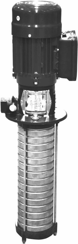
The vertical, single or multistage centrifugal immersible pump series is designed for pumping water, filtered cooling fluids or lightly aggressive, watery mediums from a storage tank. The suction side at the bottom of the pump is equipped with a stainless steel strainer. The discharge side is located at the motor stool.
Where the required duty point corresponds with the amount of stages, in some applications the immersible length has to diver from this. Therefor it is possible for the DPVCI range to use empty stages to create the required length. In that case the impellers are mounted in the casings closest to the suction casing.
The hydraulic assembly is driven by an electric motor. All hydraulic parts of the pump are made of stainless steel.
1.2Model key
Table 1: Model key Example DPVCI 10/8(18) B

1.3Operation
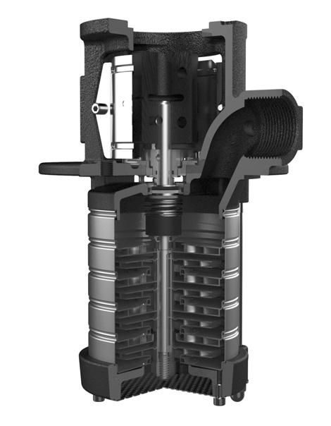
During centrifugal operation of the pump an negative pressure is created at the inlet of the first impeller. This negative pressure enables the medium to enter the pump at the suction connection at the bottom of the pump. Every impeller is placed in a stage casing. The passage of this stage determines the capacity of the pump. The diameter of the stages is related to the centrifugal forces and its “stage pressure”: the more stages, the more pressure.
This total capacity and raised pressure will be guided to the outside of the pump at the motor stool.
1.4Measuring, draining and venting
The pump is provided with plugs for measuring and venting, both located at the pump outlet connection. These connections are meant to vent the pump system when the pump is not in operation or to measure the discharge pressure of the pump using a G 1/4 connection. Also on the motor stool two connections are available to vent the storage tank.
5
DP VCI 10 /8 (18) B LabelDP Product Label Material VCI Cast Iron suction casing and motor stool, 1.4301 / AISI 304 hydraulics 10 Appr. capacity in m3/h at Qopt /8 Number of impellers
number of stages BDesign version
DPVCI
(18)Total
1.5Working range
The working range is depending on the application and the combination of pressure and temperature. For specific and detailed limits please consult the working ranges as described in the paragraph 1.8. The overall working range of the pumps can be summarised as follows:
Table 2: Specification of the working range
1.If the ambient temperature exceeds the above value or the motor is located more than 1000 m above sea level, please see 1.5.3
2.Deviation in viscosity and/or density could require an adapted motor power. Please contact your supplier for more detailed advice.
3.The free space above the motor cooling fan must be at least 1/4 of the diameter of the inlet of the cooling fan in order to have a sufficient flow of (cooling) air.
4.Pumps that are intended for 50 Hz operation, may not be connected to 60 Hz power supply.
1.5.1Minimum capacity
For minimum capacity at medium temperature of 20 oC, see table 3: for higher temperatures, see table 4 .
A minimum capacity has to be secured to prevent the pump from overheating, gathering gas, cavitation etc. The minimum capacity corresponds to all percentage of the optimum flow Qopt in relation to the temperature of the liquid pumped. Also a minimum medium level needs to be taken into consideration.
1.5.2Minimum fluid level
For ambient fluid conditions the minimum fluid level for the pumps in the storage tank is mentioned at the dimensions pages. In case of an increased required vapour pressure for fluids at higher operation temperatures, a system analyses is recommended to determine the required NPSH to avoid cavitation and air enclosure inside the pump.
1.5.3Ambient temperature and higher altitude
If the ambient temperature exceeds the maximum allowed value, or if the motor is located more than 1000 m above sea level, the motor cooling is less effective and could require an adapted motor power. See below table for the change in power output or contact your supplier for more detailed advice.
1.6Basic material variants
Table 6: Basic material variants
* see medium handled list for correct seal material
6
Table 3: Minimum capacity (Qmin)
Table 4: Minimum capacity vs.temperature (in % of Q optimum)
Table 5: Increase of required motor power
Pump type DPV note Ambient temperature [°C]-20 up to 40 1
Minimum inlet pressureNPSHreq. +
Viscosity [cSt] 1-100 2
1m
Density [kg/m3] 1000-2500 2 Cooling forced motor cooling 3
Minimum frequency [Hz] 30 Maximum frequency [Hz] 60 4
Allowable size of solids pumped 5µm
size Qmin [m3/h] 50 Hz 60 Hz 2 pole 2 pole 20,2 0,2 40,4 0,5 60,6 0,8 101,1 1,3 151,9 2.3 ID3675 3675 Ambient temperature [°C] Above sea level [m] Increase of required power 40 10000% 45 16252% 50 22505% 55 287511% 60 350018% 65 412525% 70 475033% Model
Sealing VC 1.4301JL1040EPDM* 0 5 10 15 20 25 30 35 40 405060708090100110120130140 Q[%] o
to 1mm
Hydraulic Casing
1.7Pump bearing
Medium lubricated stage bearing Tungsten Carbide against Ceramic
1.8Modular selection
To suit almost every application the pump is assembled out of modules which can be selected depending on the required working range.
Basic modules are:
• Basic pump model, which defines the capacity, pressure and basic material. Temperature range -20 up to 120 oC
• Total stages, which defines the length of the pump suitable for the storage tank.
• Sealing, which define the elastomers and the mechanical seal. A cartridge seal construction is equipped as default. Temperature and pressure range, see chapter 4.1
• Electric motor, which defines all requirements of the motor such as motor size, power, voltage, frequency and all possible motor accessories.
For assembling the total amount of stages to the motor stool an additional upper stage casing is required. Therefor when all visible stage stages are counted from the hydraulics, the sum will be the total amount of stages added by 1.
1.9Approval
CE Conformity with European Safety Directive
7
3Curves and dimensions
3.1Hydraulic performance curve DPVCI 2 B - 50Hz -2 pole
12
ID3424
20090370 E
Förderhöhe TDH Hauteur Prevalenza Opvoerhoogte Altura 0.00.51.01.52.02.53.03.5 [m³/h] 02468101 [IM.gpm]2 0 50 100 150 200 250 [m] 0 200 400 600 800 [ft] 0.00.20.40.60.81.0 [l/s] NPSHR 0 8 [m] 0 20 [ft] Eta 0 60 % Leistungsbedarf PowerInput Puiss.abs. Potenzaass. Opgenomen vermogen Potencianec.0.0 0.08 [kW] 0.0 0.1 [hp] 0.00.51.01.52.02.53.03.5 [m³/h] 2/302,2kW 2/282,2kW 2/262,2kW 2/242,2kW 2/222,2kW 2/201,5kW 2/181,5kW 2/161,5kW 2/141,1kW 2/121,1kW 2/111,1kW 2/100,75kW 2/90,75kW 2/80,55kW 2/70,55kW 2/60,55kW 2/50,37kW 2/40,37kW 2/30,37kW 2/20,37kW
Figure 5: Performance curve DPVCI 2 B - 50Hz - 2 pole
=Fördermenge/Flow/Débit/Portata/Capaciteit/Caudal 1000.0kg/m³20090370-E/0
3.2DPVCI 2 B - 50Hz - 2 pole - DIN
To determine the correct length of the pump see both following explanation and table.
length incl. motor length excl. motor
Full stage pumpF1 F2
Pump with empty stagesF3 + F4 F3 + F4 -LB
The length F3 corresponds with the length of the applied motor power. F4 corresponds with the total number of stages. Example: 2/16(30) F3=396mm, F4=732mm.
Table 8: General dimensions
*including packing
13
ID3436
ModelSeal pressure PowerMotor dimensionsDPVCI Full stage [kW]E1 [mm] E2 [mm] LB [mm] F1 [mm] F2 [mm] F3 [mm] F4 [mm] Mass* [kg] 2/2(2)PN100,3713410721944522631513014 2/3(3) 0,3713410721946624731515114 2/4(4) 0,3713410721948826931517314 2/5(5) 0,3713410721950929031519415 2/6(6) 0,5513410724355531233921617 2/7(7) 0,5513410724357633333923717 2/8(8) 0,5513410724359835533925918 2/9(9) 0,7515011523462038634028020 2/10(10) 0,7515011523464240834030220 2/11(11) 1,115011526469342937032323 2/12(12) 1,115011526471545137034523 2/14(14)PN251,115011526475849437038824 2/16(16) 1,517614128082754739643129 2/18(18) 1,517614128087059039647429 2/20(20) 1,517614128091363339651730 2/22(22) 2,217614128095667639656035 2/24(24) 2,217614128099971939660336 2/26(26) 2,2176141280104276239664636 2/28(28) 2,2176141280108580539668937 2/30(30) 2,2176141280112884839673238
3.3Hydraulic performance curve DPVCI 4 B - 50Hz - 2 pole
14
ID3448
20090373 D
Figure 6: Performance curve DPVCI 4 B - 50Hz - 2 pole
Förderhöhe TDH Hauteur Prevalenza Opvoerhoogte Altura 01234567 [m³/h] 010203 [US.gpm]0 0510152025 [IM.gpm] 0 50 100 150 200 250 [m] 0 200 400 600 800 [ft] 0.00.51.01.5 [l/s] NPSHR 0 5 [m] 0 10 [ft] Eta 0 80 % Leistungsbedarf PowerInput Puiss.abs. Potenzaass. Opgenomen vermogen Potencianec.0.0 0.2 [kW] 0.0 0.2 [hp] 01234567 [m³/h] 4/264,0kW 4/244,0kW 4/224,0kW 4/203,0kW 4/183,0kW 4/163,0kW 4/142,2kW 4/122,2kW 4/112,2kW 4/101,5kW 4/91,5kW 4/81,5kW 4/71,1kW 4/61,1kW 4/50,75kW 4/40,55kW 4/30,55kW 4/20,37kW
=Fördermenge/Flow/Débit/Portata/Capaciteit/Caudal 1000.0kg/m³20090372-D/0
3.4DPVCI 4 B - 50Hz - 2 pole - DIN
To determine the correct length of the pump see both following explanation and table.
length incl. motor length excl. motor
Full stage pumpF1 F2
Pump with empty stagesF3 + F4 F3 + F4 -LB
The length F3 corresponds with the length of the applied motor power. F4 corresponds with the total number of stages. Example: 4/16(22) F3=442mm, F4=560mm.
*including packing
15
Table 9: General dimensions
ID3436
ModelSeal pressure PowerMotor dimensionsDPVCI Full stage [kW] E1 [mm] E2 [mm] LB [mm] F1 [mm] F2 [mm] F3 [mm] F4 [mm] Mass* [kg] 4/2(2)PN100,3713410721944522631613014 4/3(3) 0,5513410724349024733915116 4/4(4) 0,5513410724351226933917316 4/5(5) 0,7515011523453430034019419 4/6(6) 1,115011526458632237021621 4/7(7) 1,115011526460734337023722 4/8(8) 1,517614128065537539625926 4/9(9) 1,517614128067639639628026 4/10(10) 1,517614128069841839630226 4/11(11) 2,217614128071943939632330 4/12(12)PN252,217614128074146139634530 4/14(14) 2,217614128078450439638831 4/16(16) 319514531687355744243143 4/18(18) 319514531691660044247443 4/20(20) 319514531695964344251744 4/22(22) 4223167324101068645056054 4/24(24) 4223167324105372945060355 4/26(26) 4223167324109677245064672 4/26(28) 4223167324113981545068974 4/26(30) 4223167324118285845073274
3.5Hydraulic performance curve DPVCI 6 B - 50Hz - 2 pole
16
ID3425
20090374 E
Figure 7: Performance curve DPVCI 6 B - 50Hz - 2 pole
Förderhöhe TDH Hauteur Prevalenza Opvoerhoogte Altura 024681 [m³/h]0 01020304 [US.gpm]0 010203 [IM.gpm]0 0 50 100 150 200 250 [m] 0 200 400 600 800 [ft] 0.00.51.01.52.02.5 [l/s] NPSHR 0 4 [m] 0 10 [ft] Eta 0 80 % Leistungsbedarf PowerInput Puiss.abs. Potenzaass. Opgenomen vermogen Potencianec.0.0 0.2 [kW] 0.0 0.3 [hp] 024681 [m³/h]0 6/265,5kW 6/245,5kW 6/225,5kW 6/184,0kW 6/164,0kW 6/143,0kW 6/123,0kW 6/113,0kW 6/102,2kW 6/92,2kW 6/82,2kW 6/71,5kW 6/61,5kW 6/51,1kW 6/41,1kW 6/30,75kW 6/20,37kW 6/205,5kW
=Fördermenge/Flow/Débit/Portata/Capaciteit/Caudal 1000.0kg/m³20090374-E/0
3.6DPVCI 6 B - 50Hz - 2 pole - DIN
To determine the correct length of the pump see both following explanation and table.
length incl. motor length excl. motor
Full stage pumpF1 F2
Pump with empty stagesF3 + F4 F3 + F4 -LB
The length F3 corresponds with the length of the applied motor power. F4 corresponds with the total number of stages. Example: 6/12(26) F3=442mm, F4=740mm.
Table 10: General dimensions
*including packing
17
ID3436
ModelSeal pressure PowerMotor dimensionsDPVCI [kW] E1 [mm] E2 [mm] LB [mm] F1 [mm] F2 [mm] F3 [mm] F4 [mm] Mass* [kg] 6/2(2)PN100,3713410721945523631614014 6/3(3) 0,7515011523450527134016518 6/4(4) 1,115011526456029637019021 6/5(5) 1,115011526458532137021521 6/6(6) 1,517614128063635639624025 6/7(7) 1,517614128066138139626526 6/8(8) 2,217614128068640639629029 6/9(9) 2,217614128071143139631529 6/10(10) 2,217614128073645639634030 6/11(11)PN25319514531680749144236541 6/12(12) 319514531683251644239042 6/14(14) 319514531688256644244042 6/16(16) 422316732494061645049052 6/18(18) 422316732499066645054053 6/20(20) 5.5266178329112179253159088 6/22(22) 5.5266178329117184253164089 6/24(24) 5.5266178329122189253169090 6/26(26) 5.5266178329127194253174091 6/26(28) 5.5266178329132199253179091 6/26(30) 5.52661783291371104253184092
3.7Hydraulic performance curve DPVCI 10 B - 50Hz - 2 pole
18
ID3425
20101080 A
Figure 8: Performance curve DPVCI 10 B - 50Hz- 2 pole
Förderhöhe TDH Hauteur Prevalenza Opvoerhoogte Altura 0246810121 [m³/h]4 0102030405 [IM.gpm]0 0 50 100 150 200 250 [m] 0 200 400 600 800 [ft] 01234 [l/s] NPSHR 0 5 [m] 0 10 [ft] Eta 0 80 % Leistungsbedarf PowerInput Puiss.abs. Potenzaass. Opgenomen vermogen Potencianec.0.0 0.4 [kW] 0 0.4 [hp] 0246810121 [m³/h]4 10/217,5kW 10/197,5kW 10/177,5kW 10/155,5kW 10/135,5kW 10/114kW 10/104kW 10/94kW 10/83kW 10/73kW 10/62,2kW 10/52,2kW 10/41,5kW 10/31,1kW 10/20,75kW 10/10,75kW
=Fördermenge/Flow/Débit/Portata/Capaciteit/Caudal 1000.0kg/m³20101080-A/0
3.8DPVCI 10 B - 50Hz - 2 pole - DIN
To determine the correct length of the pump see both following explanation and table.
length incl. motor length excl. motor
Full stage pumpF1 F2
Pump with empty stagesF3 + F4 F3 + F4 -LB
The length F3 corresponds with the length of the applied motor power. F4 corresponds with the total number of stages. Example: 10/8(13) F3=455mm, F4=445mm.
Table 11: General dimensions
19
ID3436
ModelSeal pressure PowerMotor dimensionsDPVCI Full stage [kW]E1 [mm] E2 [mm] LB [mm] F1 [mm] F2 [mm] F3 [mm] F4 [mm] Mass* [kg] 10/1(2)PN100,7515011523449726334315417 10/2(2) 0,7515011523449726334315417 10/3(3) 1,115011526455429037318120 10/4(4) 1,517614128060632639920732 10/5(5) 2,217614128063335339923636 10/6(6) 2,217614128068640639928737 10/7(7) 319514531673241645531347 10/8(8) 319514531675844244531348 10/9(9)PN25422316732479246845333958 10/10(10) 422316732481949545336658 10/11(11) 422316732484552145339259 10/13(13) 5,526617832998465553944593 10/15(15) 5,5266178329103770853949894 10/17(17) 7,52661783771138761587551127 10/19(19) 7,52661783771191814587604129 10/21(21) 7,52661783771244867587657130
*including packing
3.9Hydraulic performance curve DPVCI 15 C - 50Hz - 2 pole
*Decreased motor power: Qmax = 19 m³/h
**Power input based on a V 15/3 C of this hydraulic speed design
20
ID3425
20210121 B
Figure 9: Performance curve DPVCI 15 C - 50Hz - 2 pole
Förderhöhe TDH Hauteur Prevalenza Opvoerhoogte Altura 0510152025 [m³/h] 02040608010 [US.gpm]0 02040608 [IM.gpm]0 0 50 100 150 200 250 [m] 0 200 400 600 800 [ft] 0246 [l/s] NPSHR 0 3 [m] 0 5 [ft] Eta 0 80 % Leistungsbedarf** PowerInput Puiss.abs. Potenzaass. Opgenomen vermogen Potencianec.0 1 [kW] 0 1 [hp] 0510152025 [m³/h] 15/1718,5kW 15/1515,0kW 15/1315,0kW 15/1111,0kW 15/1011,0kW 15/911,0kW 15/811,0/7,5*kW 15/77,5kW 15/67.5/5,5*kW 15/55,5kW 15/44,0kW 15/33,0kW 15/22,2kW 15/11,1kW
=Fördermenge/Flow/Débit/Portata/Capaciteit/Caudal 1000.0kg/m³20210121-B/0
3.10DPVCI 15 C - 50Hz - 2 pole - DIN
To determine the correct length of the pump see both following explanation and table.
length incl. motor length excl. motor
Full stage pumpF1 F2
Pump with empty stagesF3 + F4 F3 + F4 -LB
The length F3 corresponds with the length of the applied motor power. F4 corresponds with the total number of stages. Example: 15/3(15) F3=445mm, F4=498mm.
Table 12: General dimensions
*including packing
1.Decreased power
21
ID3436
ModelSeal pressure PowerMotor dimensionsDPVCI Full stage [kW]E1 [mm] E2 [mm] LB [mm] F1 [mm]F2 [mm]F3 [mm] F4 [mm] Mass* [kg] 15/1(2)PN101,115011526457831439419827 15/2(2) 2,220024828160532442119838 15/3(3) 321515731769237546723947 15/4(4) 424816835677241650628057 15/5(5) 5,528819743297053866332198 15/6(6) 5,5 1
2881974321011579663321100 15/6(6) 7,52881974321011579663362100 15/7(7)PN167,5 2881974321052620663403101 15/8(8) 7,5 1 2881974321193661663444163 15/8(8) 113402235331194661764444163 15/9(9) 113402235331235702764485185 15/10(10) 113402235331276743764526187 15/11(11) 113402235331317784764567188 15/13(13) 153402235331399866764649201 15/15(15)PN25153402235331481948764731204 15/17(17) 18,534022353315631030764813217
3.11Hydraulic performance curve DPVCI 2 B - 60Hz -2 pole
22
ID3424
20090371 E
Figure 10: Performance curve DPVCI 2 B - 60Hz - 2 pole
Förderhöhe TDH Hauteur Prevalenza Opvoerhoogte Altura 0.00.51.01.52.02.53.03.54.0 [m³/h] 051015 [US.gpm] 051015 [IM.gpm] 0 50 100 150 200 250 [m] 0 200 400 600 800 [ft] 0.00.20.40.60.81.0 [l/s] NPSHR 0 10 [m] 0 20 [ft] Eta 0 80 % Leistungsbedarf PowerInput Puiss.abs. Potenzaass. Opgenomen vermogen Potencianec. 0.1 0.04 0.14 [kW] 0.10 0.15 [hp] 0.00.51.01.52.02.53.03.54.0 [m³/h] 2/223,0kW 2/203,0kW 2/182,2kW 2/162,2kW 2/142,2kW 2/121,5kW 2/91,1kW 2/111,5kW 2/101,5kW 2/81,1kW 2/71,1kW 2/60,75kW 2/50,75kW 2/40,55kW 2/30,37kW 2/20,37kW
=Fördermenge/Flow/Débit/Portata/Capaciteit/Caudal 1000.0kg/m³20090371-E/0
3.12DPVCI 2 B - 60Hz - 2 pole - DIN
To determine the correct length of the pump see both following explanation and table.
length incl. motor length excl. motor
Full stage pumpF1 F2
Pump with empty stagesF3 + F4 F3 + F4 -LB
The length F3 corresponds with the length of the applied motor power. F4 corresponds with the total number of stages. Example: 2/3(22) F3=315mm, F4=560mm.
Table 13: General dimensions
*including packing
23
ID3436
ModelSeal pressure PowerMotor dimensionsDPVCI Full stage [kW]E1 [mm] E2 [mm] LB [mm] F1 [mm] F2 [mm] F3 [mm] F4 [mm] Mass* [kg] 2/2(2)PN100,3713410721944522631513014 2/3(3) 0,3713410721946624731515114 2/4(4) 0,5513410724351226933917316 2/5(5) 0,7515011523453430034019418 2/6(6) 0,7515011523455632234021619 2/7(7) 1,115011526460734337023722 2/8(8) 1,115011526462936537025922 2/9(9) 1,115011526465038637028022 2/10(10)PN251,517614128069841839630226 2/11(11) 1,517614128071943939632327 2/12(12) 1,517614128074146139634527 2/14(14) 2,217614128078450439638831 2/16(16) 2,217614128082754739643132 2/18(18) 2,217614128087059039647432 2/20(20) 319514531695964344251744 2/22(22) 3195145316100268644256045 2/22(24) 3195145316104572944260345 2/22(26) 3195145316108877244264645 2/22(28) 3195145316113181544268946 2/22(30) 3195145316117485644273264
3.13Hydraulic performance curve DPVCI 4 B - 60Hz - 2 pole
24
ID3448
20090373 E
Figure 11: Performance curve DPVCI 4 B - 60Hz - 2 pole
Förderhöhe TDH Hauteur Prevalenza Opvoerhoogte Altura 012345678 [m³/h] 010203 [US.gpm]0 0102 [IM.gpm]0 0 50 100 150 200 250 [m] 0 200 400 600 800 [ft] 0.00.51.01.52.0 [l/s] NPSHR 0 8 [m] 0 20 [ft] Eta 0 80 % Leistungsbedarf PowerInput Puiss.abs. Potenzaass. Opgenomen vermogen Potencianec.0.0 0.3 [kW] 0.0 0.4 [hp] 012345678 [m³/h] 4/185,5kW 4/165,5kW 4/144,0kW 4/124,0kW 4/113,0kW 4/103,0kW 4/93,0kW 4/82,2kW 4/72,2kW 4/61,5kW 4/51,5kW 4/41,1kW 4/30,75kW 4/20,55kW
=Fördermenge/Flow/Débit/Portata/Capaciteit/Caudal 1000.0kg/m³20090373-E/0
3.14DPVCI 4 B - 60Hz - 2 pole - DIN
To determine the correct length of the pump see both following explanation and table.
length incl. motor length excl. motor
Full stage pumpF1 F2
Pump with empty stagesF3 + F4 F3 + F4 -LB
The length F3 corresponds with the length of the applied motor power. F4 corresponds with the total number of stages. Example: 4/7(16) F3=396mm, F4=431mm.
Table 14: General dimensions
*including packing
25
ID3436
ModelSeal pressure PowerMotor dimensionsDPVCI Full stage [kW] E1 [mm] E2 [mm] LB [mm] F1 [mm] F2 [mm] F3 [mm] F4 [mm] Mass* [kg] 4/2(2)PN100,5513410724346922633913016 4/3(3) 0,7515011523449125734015118 4/4(4) 1,115011524354327937017321 4/5(5) 1,517614126459031039619425 4/6(6) 1,517614128061233239621625 4/7(7) 2,217614128063335339623728 4/8(8) 2,217614128065537539625929 4/9(9)PN25319514531672240644228040 4/10(10) 319514531674442844230241 4/11(11) 319514531676544944232341 4/12(12) 422316732479547145034550 4/14(14) 422316732483851445038851 4/16(16) 5,526617832996263353143184 4/18(18) 5,5266178329100567653147485 4/18(20) 5,5266178329104871953151785 4/18(22) 5,5266178329109176253156088 4/18(24) 5,5266178329113480553160388 4/18(26) 5,5266178329117784853164689 4/18(28) 5,5266178329122089153168989 4/18(30) 5,5266178329126393453173289
3.15Hydraulic performance curve DPVCI 6 B - 60Hz - 2 pole
26
ID3425
20090375
Figure 12: Performance curve DPVCI 6 B - 60Hz - 2 pole
Förderhöhe TDH Hauteur Prevalenza Opvoerhoogte Altura 02468101 [m³/h]2 0102030405 [US.gpm]0 01020304 [IM.gpm]0 0 50 100 150 200 250 [m] 0 200 400 600 800 [ft] 0123 [l/s] NPSHR 0 6 [m] 0 10 [ft] Eta 0 80 % Leistungsbedarf PowerInput Puiss.abs. Potenzaass. Opgenomen vermogen Potencianec.0.0 0.4 [kW] 0 0.4 [hp] 02468101 [m³/h]2 6/187,5kW 6/167,5kW 6/145,5kW 6/125,5kW 6/114,0kW 6/104,0kW 6/94,0kW 6/83,0kW 6/73,0kW 6/62,2kW 6/52,2kW 6/41,5kW 6/31,1kW 6/20,75kW 6/10,37kW
F =Fördermenge/Flow/Débit/Portata/Capaciteit/Caudal 1000.0kg/m³20090375-F/0
3.16DPVCI 6 B - 60Hz - 2 pole - DIN
To determine the correct length of the pump see both following explanation and table.
length incl. motor length excl. motor
Full stage pumpF1 F2
Pump with empty stagesF3 + F4 F3 + F4 -LB
The length F3 corresponds with the length of the applied motor power. F4 corresponds with the total number of stages. Example: 6/2(18) F3=340mm, F4=540mm.
Table 15: General dimensions
*including packing
27
ID3436
ModelSeal pressure PowerMotor dimensionsDPVCI Full stage [kW] E1 [mm] E2 [mm] LB [mm] F1 [mm] F2 [mm] F3 [mm] F4 [mm] Mass* [kg] 6/2(2)PN100,7515011523448024634014017 6/3(3) 1,115011516453527137016520 6/4(4) 1,517614128058630639619024 6/5(5) 2,217614128061133139621528 6/6(6) 2,2176141280639635639624028 6/7(7) 319514531670739144226539 6/8(8)PN25319514531673241644229040 6/9(9) 422316732476544145031549 6/10(10) 422316732479046645034050 6/11(11) 422316732481549145036550 6/12(12) 5,526617832992159253139083 6/14(14) 5,526617832997164253144084 6/16(16) 7,52661783771069692579490116 6/18(18) 7,52661783771119742579540117 6/18(20) 7,52661783771169792579590117 6/18(22) 7,52661783771219842579640117 6/18(24) 7,52661783771269892579690118 6/18(26) 7,52661783771319942579740118 6/18(28) 7,52661783771369992579790118 6/18(30) 7,526617837714191042579840119
3.17Hydraulic performance curve DPVCI 10 B - 60Hz - 2 pole
28
ID3425
20101081 B
Figure 13: Performance curve DPVCI 10 B - 60Hz- 2 pole
Förderhöhe TDH Hauteur Prevalenza Opvoerhoogte Altura 024681012141 [m³/h]6 020406 [US.gpm]0 0204 [IM.gpm]0 0 50 100 150 200 250 [m] 0 200 400 600 800 [ft] 01234 [l/s] NPSHR 5 1 [m]10 [ft] Eta 0 80 % Leistungsbedarf PowerInput Puiss.abs. Potenzaass. Opgenomen vermogen Potencianec.0 0.8 [kW] 0 1 [hp] 024681012141 [m³/h]6 10/1511kW 10/1311kW 10/117,5kW 10/107,5kW 10/97,5kW 10/85,5kW 10/75,5kW 10/64kW 10/54kW 10/43kW 10/32,2kW 10/21,5kW 10/10,75kW
=Fördermenge/Flow/Débit/Portata/Capaciteit/Caudal 1000.0kg/m³20101081-B/0
3.18DPVCI 10 B - 60Hz - 2 pole - DIN
To determine the correct length of the pump see both following explanation and table.
length incl. motor length excl. motor
Full stage pumpF1
Pump with empty stagesF3 + F4
The length F3 corresponds with the length of the applied motor power. F4 corresponds with the total number of stages. Example: 10/1(6) F3=343mm, F4=287mm.
Table 16: General dimensions
29
F2
ID3436
ModelSeal pressure PowerMotor dimensionsDPVCI Full stage [kW]E1 [mm] E2 [mm] LB [mm] F1 [mm] F2 [mm] F3 [mm] F4 [mm] Mass* [kg] 10/1(2)PN100,7515011523449726334315417 10/2(2) 1,517611528055327339915430 10/3(3) 2,217611528058030039918134 10/4(4) 319514131665233644520745 10/5(5) 422314132468736345323455 10/6(6) 422314132474041645328756 10/7(7)PN255,526617832982649753928771 10/8(8) 5,526617832985252353931372 10/9(9) 7,5266178377926549587339119 10/10(10) 7,5266178377953576587366120 10/11(11) 7,5266178377979602587392121 10/13(13) 113152044981183685738445178 10/15(15) 113152044981236738738498179 10/15(17) 113152044981289791738551183 10/15(19) 113152044981342844738604184 10/15(21) 113152044981395897738657184
F3 + F4 -LB
*including packing
3.19Hydraulic performance curve DPVCI 15 C - 60Hz - 2 pole
30
ID3425
20210122
Figure 14: Performance curve DPVCI 15 C - 60Hz - 2 pole
A
Förderhöhe TDH Hauteur Prevalenza Opvoerhoogte Altura 51015202 05 [m³/h] 020406080100120 [US.gpm] 020406080100 [IM.gpm] 0 50 100 150 200 250 [m] 0 200 400 600 800 [ft] 02468 [l/s] NPSH 0 6 [m] 0 10 [ft] Eta 0 80 % Leistungsbedarf* PowerInput Puiss.abs. Potenzaass. Opgenomen vermogen Potencianec.0 2 [kW] 0 2 [hp] 0510152025 [m³/h] 8.5W11k15/1 108.5kW15/1 1515/9kW 1515/8kW 1515/7kW 15/611kW 5kW15/11 7.515/4kW 5kW5.15/3k 15/24kW 1kW15/2.2 R
=Fördermenge/Flow/Débit/Portata/Capaciteit/Caudal 1000.0kg/m³20210122-A/0
3.20DPVCI 15 C - 60Hz - 2 pole - DIN
To determine the correct length of the pump see both following explanation and table.
length incl. motor length excl. motor
Full stage pumpF1 F2
Pump with empty stagesF3 + F4 F3 + F4 -LB
The length F3 corresponds with the length of the applied motor power. F4 corresponds with the total number of stages. Example: 15/4(11) F3=587mm, F4=392mm.
Table 17: General dimensions
*including packing
31
ID3436
ModelSeal
PowerMotor dimensionsDPVCI Full stage [kW]E1 [mm] E2 [mm] LB [mm] F1 [mm] F2 [mm] F3 [mm] F4 [mm] Mass* [kg] 15/1(2)PN102,220014828160532442119837 15/2(2) 424816835669033450619853 15/3(3) 5,528819743288845666323985 15/4(4) 7,528819743292949766328086 15/5(5)PN16113402235331071538764321157 15/6(6) 113402235331112579764362158 15/7(7) 153402235331153620764403170 15/8(8)PN25153402235331194661764444170 15/9(9) 153402235331235702764485193 15/10(10) 18,53402235331276743764526204 15/11(11) 18,53402235331317784764567204 15/11(13) 18,53402235331399866764649205 15/11(15) 18,53402235331481948764731206 15/11(17) 18,534022353315631030764813207
pressure