7 minute read
Preferably Wired After All
Tips for Developing a 1 Gbit/s Interface in an Industrial Environment
By Dr. Heinz Zenkner (Freelance Consultant at Würth Elektronik)
Wireless networks are becoming increasingly popular, especially in industrial applications. However, there is a strong case for robust cabling via Ethernet in many cases as the more reliable and secure option. This article demonstrates how to easily implement a 1 Gbit/s interface.
Industrial wireless sensor networks can be established using smart sensors and meters that use efficient modulation and coding techniques with good propagation characteristics and low bandwidths. However, the majority of the use cases explored are limited to low throughput applications. For these use cases the actual throughput is often no more than 1 Mbit/s.
There are no definitive boundaries in a wireless network. For example, even minor adjustments to the access point’s antenna positioning can have a significant effect on the signal strength at the other stations. The signal is attenuated by walls, ceilings, and floors, and reflected by metallic objects. While a station may be able to receive the signal from an access point, the access point in turn may not be able to receive the station’s signal. In addition, there is a possibility that the network could be accessed from the outside or that the wireless signal transmission could be interfered with.
As a result, wireless data transmission is intrinsically less reliable than transfers through a wired network. Thus, particularly in industrial settings, there may be instances where a wired Ethernet network is the only viable solution.
Wired Ethernet Network
Similar to wireless networks, wired networks work by exchanging Ethernet frames between endpoints. There are a few rules to follow when setting up a network to avoid problems. The most common cause of network problems is
rule breaches. For example, in Ethernet, wire length must not be arbitrary. When cascading, i.e., connecting hubs in series, an arbitrary number of hubs is not permitted, and an unfavorable network configuration can also lead to errors or add unnecessary loads on the network. However, depending on the cable quality and the performance of the hardware, the expected data rates are often not achievable.
Currently, 100Base-TX (100 Mbit/s Fast Ethernet), Gigabit Ethernet (1 Gbit/s), 10 Gigabit Ethernet (10 Gbit/s) and 100 Gigabit Ethernet (100 Gbit/s) are available. For most applications, Gigabit Ethernet works well with regular Ethernet cables, specifically CAT5e and CAT6 cabling standards. These cable types adhere to the 1000BASE-T wiring standard, alternatively referred to as IEEE 802.3ab.
The 1 GB Ethernet interface conforms to the 802.3ab-1999 (CL40) standard and requires four wire pairs/channels for signal transmission. This results in a symbol rate of 125 Megabaud (MBd) and a bandwidth of 62.5 MHz per channel (2 bits per symbol). The signal voltage at 1000BASE-T (GB Ethernet) is typically 750 mV differential, for the limits 820 mV > VSignal > 670 mV at a load of 100 Ω.
1 Gbit/s Ethernet Front-End
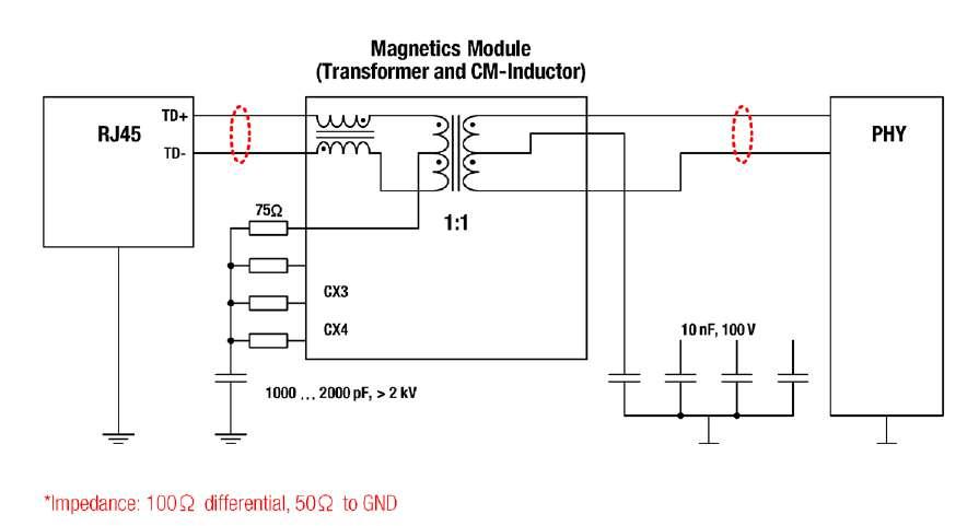
A typical front-end for Ethernet is equipped with an RJ45 port. These are intended for full-duplex transmissions, i.e. simultaneous transmission of send and receive data. This is possible because the connector contains two pairs of wires, one in each direction (differential voltage principle). The IEEE standard specifies galvanic separation via a transformer for each RJ45 connection. This transformer protects the devices from damage caused by the line’s high voltage and prevents voltage offsets caused by potential variations between the devices. The circuit diagram for a Gigabit Ethernet interface is shown in Figure 1.
The Ethernet transformer (LAN transformer) is the device-to-Ethernet cable interface. The transformer provides the necessary galvanic isolation between the device and the cable while at the same time matching the impedance of internal logic and the balanced wire pairs. Furthermore, the transformer protects the device from transient interference and suppresses common mode signals between the transceiver IC and the cable, both within the device and between the external cable and the device’s electronics. However, the device must also be capable of transmitting data at a rate of up to 1 Gbit/s without significantly degrading the transmit and receive signals. Additional components are needed to meet the matching and electromagnetic compatibility (EMC) criteria.
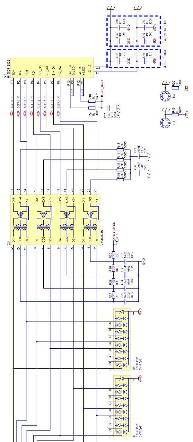
Figure 2 depicts a circuit diagram of the Gigabit Ethernet interface using discrete components. The LAN transformer provides DC isolation between the electronics and the network cable. The primary-side winding’s middle tap depicts the so-called “Bob Smith” termination.

Figure 1: Basic circuit of a Gigabit Ethernet interface. Representation of a transmission channel with a total of four channels. (Source: Würth Elektronik)

Figure 2: A Gigabit Ethernet interface’s discrete circuit. Module X3 contains the LAN transformers and common-mode chokes necessary to prevent interference. Here, one 75-Ω resistor is connected to each wire pair to form a “star point”, which is then galvanically isolated and connected to the housing ground via two parallel 100-pF/2-kV capacitors. The additional common-mode chokes integrated in module X3 mitigate interference that is coupled both capacitively and inductively via the long Ethernet cables and could potentially impair Ethernet data communication as common-mode interference.
In Figure 2, R9, R10 and C52 are used to power the LEDs that are typically integrated in the connector socket. Through the capacitors C36 to C38 and C41 to C43, the shielding of the Ethernet socket can be connected to the board ground (GND). For sheet metal housings, it makes sense to omit these capacitors and connect the electronics’ ground (GND) directly to the housing via screw connections. For plastic housings the capacitors should be fitted to connect the shield of the Ethernet cable to the reference ground. The 0-Ω resistors R19 and R20 have the same purpose. However, unlike with capacitors, there is no galvanic separation here. Alternative configurations were included in this section for “experimental” purposes to compare the shielding quality of various Ethernet cables. The capacitors C32 to C35 on the secondary side of the transformers connect the center taps of these in an RF manner to ground (GND). Galvanic isolation via capacitors is essential to eliminate DC equalization currents from the PHY. The resistors R27 to R30 are included to comply with some PHY manufacturers requirements (Current Mode Line Driver - Option) but are typically not needed if the PHY operates in “Standard Voltage Mode”. However, the TVS diode arrays D6 and D7 are indispensable because they isolate transient interferences on the interface side of the PHY from the circuit ground (GND). On the secondary side, i.e. after the transformers of the X3 module, transient disturbances occur in common mode, and therefore a TVS diode must be connected to each terminal of the transformers against the reference ground. The secondary side of the transformer,
however, has lower interference levels than the primary side. Important for the TVS diodes to function properly is a low-impedance connection of the diodes, on the one hand looped into the signal lines and on the other hand to ground.
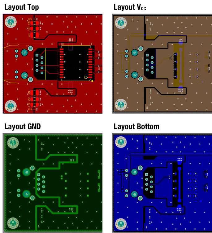
Figure 3 illustrates the layout of all four layers of the board starting with the Ethernet interface area. The package/socket ground is isolated from the electronics GND in all four layers. Thus, the package ground’s surfaces do not overlap with those of other layers to keep capacitive coupling as low as possible. The ground planes were plated through every 4 mm in a grid pattern. The Ethernet socket’s signal lines are balanced, with a differential impedance of 100 Ω routed to the reference ground. The conductor pairs have a track width of 0.154 mm and are spaced 0.125 mm apart. The Ethernet socket is positioned on the PCB’s edge to ensure a low-impedance connection to a metal enclosure if necessary.
The transformer module (X3) is placed nearby to minimize the effects of electrical coupling, or interference from long traces. As with the primary side, the secondary side of the transformer module must maintain a differential impedance of 100 Ω to the reference ground for the conductor paths. To avoid voltage drop due to parasitic inductance, the TVS arrays must be connected directly into the signal path and to GND.
EMC Compliance
In terms of electromagnetic compatibility (EMC), the board complies with industry standards for immunity (EN61000-6-2) and EN55032 Class B radio interference emission levels for multimedia equipment. Numerous factors must be considered when designing a 1 Gbit/s Ethernet interface. These include an RF-compati-

Figure 3: The layout of all four board layers of the Ethernet interface area.
ble circuit and layout design, a system-dependent ground concept, and the right choice of components. Only when all these factors are taken into account a product that functions reliably and meets stringent requirements can be developed. Further information on these topics, as well as on other interface standards, is available in various app notes published by Würth Elektronik at [1].
220182-01
About the Author
Dr.-Ing. Heinz Zenkner is a freelance consultant at Würth Elektronik in the areas of technical marketing and application engineering as well as a lecturer at the technical academy in the area of EMC. At the same time, Heinz is a publicly appointed and sworn EMC expert. He has authored numerous technical journals and books, and has worked as a lecturer at various universities, the IHK and at numerous seminars.
WEB LINKS
[1] Würth Elektronik Application Guide: https://www.we-online.com/applicationguide/en


