Get Started with the NXP FRDM-MCXN947 Development Board
Get Started with the NXP FRDM-MCXN947 Development Board
Develop projects on connectivity, graphics, machine learning, motor control, and sensors
Get Started with the FRDM-MCXN947
Development Board
●
Dogan Ibrahim
● This is an Elektor Publication. Elektor is the media brand of Elektor International Media B.V. PO Box 11, NL-6114-ZG Susteren, The Netherlands Phone: +31 46 4389444
● All rights reserved. No part of this book may be reproduced in any material form, including photocopying, or storing in any medium by electronic means and whether or not transiently or incidentally to some other use of this publication, without the written permission of the copyright holder except in accordance with the provisions of the Copyright Designs and Patents Act 1988 or under the terms of a licence issued by the Copyright Licencing Agency Ltd., 90 Tottenham Court Road, London, England W1P 9HE. Applications for the copyright holder's permission to reproduce any part of the publication should be addressed to the publishers.
● Declaration
The authors and publisher have used their best efforts in ensuring the correctness of the information contained in this book. They do not assume, and hereby disclaim, any liability to any party for any loss or damage caused by errors or omissions in this book, whether such errors or omissions result from negligence, accident or any other cause.
Prepress Production: D-Vision, Julian van den Berg
Printers: Ipskamp, Enschede, The Netherlands
Elektor is the world's leading source of essential technical information and electronics products for pro engineers, electronics designers, and the companies seeking to engage them. Each day, our international team develops and delivers high-quality content - via a variety of media channels (including magazines, video, digital media, and social media) in several languages - relating to electronics design and DIY electronics. www.elektormagazine.com
5.5
5.7
Preface
It is becoming important for microcontroller users to adapt to new technologies quickly and learn the architecture and use of high performance 32-bit microcontrollers. Several manufacturers offer 32-bit microcontrollers as general-purpose processors in embedded applications. For example, Microchip Inc offers the 32-bit PIC family of microcontrollers and development tools in addition to their highly popular 8-bit and 24-bit family. Companies like NXP Semiconductors, STMicroelectronics and several others offer ARM based processors for high-speed professional applications.
ARM offers 32-bit and 64-bit processors for the embedded applications. Nowadays, majority of mobile devices such as mobile phones, tablets, and GPS receivers are based on the ARM processors. The low cost, low power consumption, and high performance of the ARM processors make them ideal candidates to be used in complex communication and mixed signal applications.
This book is about the use of the FRDM-MCXN947 Development Board, developed and manufactured by NXP Semiconductors. This is a complex low-cost through-hole USB-powered PCB. At its heart lies the MCXNx4x family MCU, featuring NXP's advanced implementation of the Arm Dual Cortex-M33 TrustZone microcontroller. This microcontroller operates at speeds of up to 150 MHz to provide high CPU performance and best real-time response. It is supported by Zephyr OS for developing Internet of Things with a free, open-source embedded operating system. Popular development IDE tools such as the MCUXpresso IDE, MCUXpresso for VS Code, IAR Embedded Workbench, or the Keil MDK can be used for program development. Additionally, a powerful SDK is provided which simplifies program development greatly. The board is shipped with 2 MB dual-bank on-chip flash, 512 KB RAM, 10 x LP Flexcomms each supporting SPI, I2C, and UART, 2 x FlexCAN, Ethernet, on-board MCU-Link debugger with CMSIS-DAP, ADC, DAC, RTC, digital MEMS microphone interface, LCD interface, capacitive touch sensor interface, OpAmp, analog comparators, many timers, etc.
One of the important features of the development board is that it supports N1-16 Neural Processing Unit (NPU), thus enabling users to develop AI based projects. The development board also supports Arduino UNO form factor header pins, making it compatible with many Arduino shields, mikroBUS connector for mikroElektronica Click Boards, and Pmod connector.
One of the nice things of the FRDM-MCXN947 development board is that several onboard debug probes are provided with so that programmers can debug their programs by communicating directly with the MCU. With the help of the debugger, programmers can single step through a program, insert breakpoints, view and modify variables and so on.
Many working and tested projects have been developed in the book using the popular MCUXpresso IDE and the SDK with various sensors and actuators. The project descriptions, block diagrams, circuit diagrams, complete program listings, and detailed descriptions of all the developed programs are given in the book for all the projects. Use of the popular CMSIS-DSP library is also explained with several commonly used matrix operations.
The projects provided in the book can be used without any modifications in many applications. Alternatively, readers can base their projects to the ones given in the book during the development of their own projects. The author hopes that readers use the FRDM-MCXN947 development board in their future projects.
Hope you enjoy reading the book.
Dr. Dogan Ibrahim
Chapter 1 • The FRDM-MCXN947 Development Board
1.1 Overview
The FRDM-MCXN947 is a compact and scalable development board for rapid prototyping of the MCX N94 (and the N54) MCUs. The board offers industry standard headers for easy access to the MCU's I/Os, integrated open-standard serial interfaces, external flash memory and an on-board MCU-Link debugger.
This book provides detailed information and various projects on using this development board. In this chapter, you will get to know the most commonly used features of the FRDMMCXN947 Development Board.
1.2 The FRDM-MCXN947 Development Board hardware
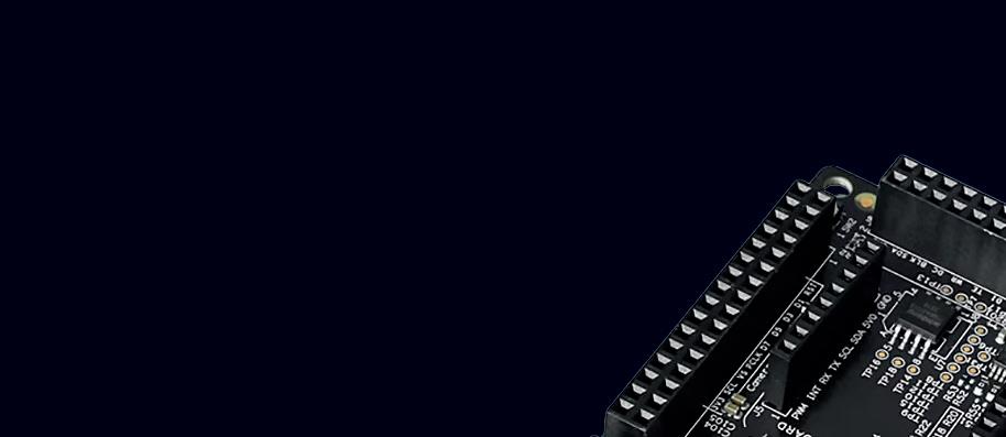
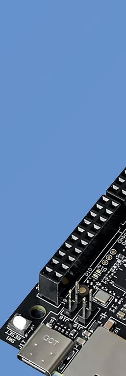
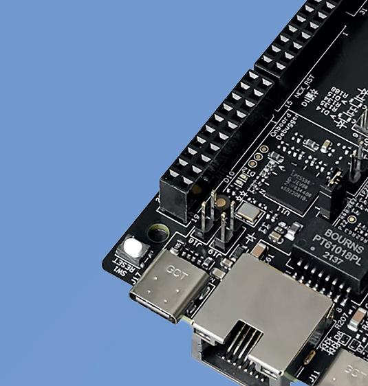
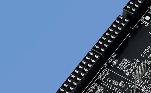
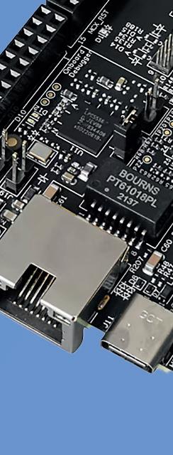
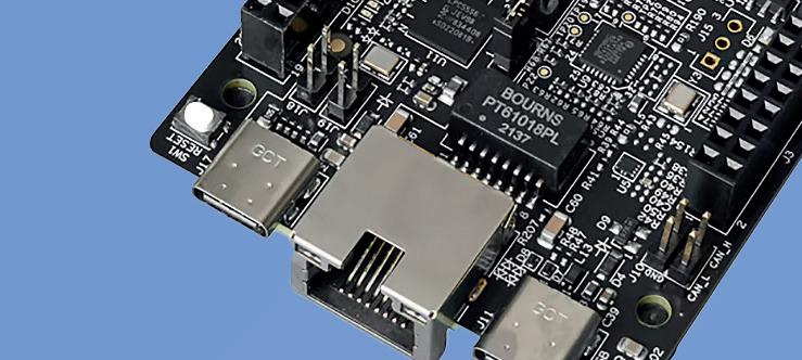
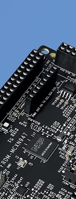
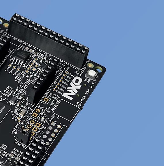
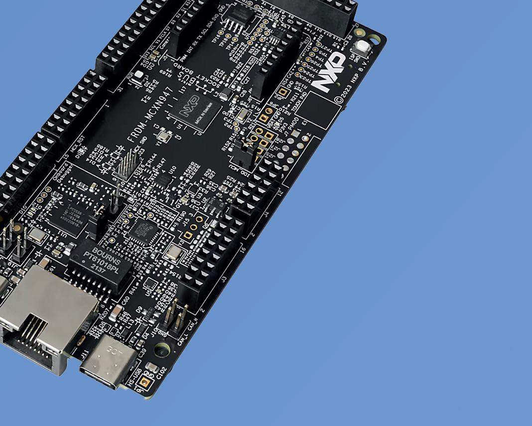
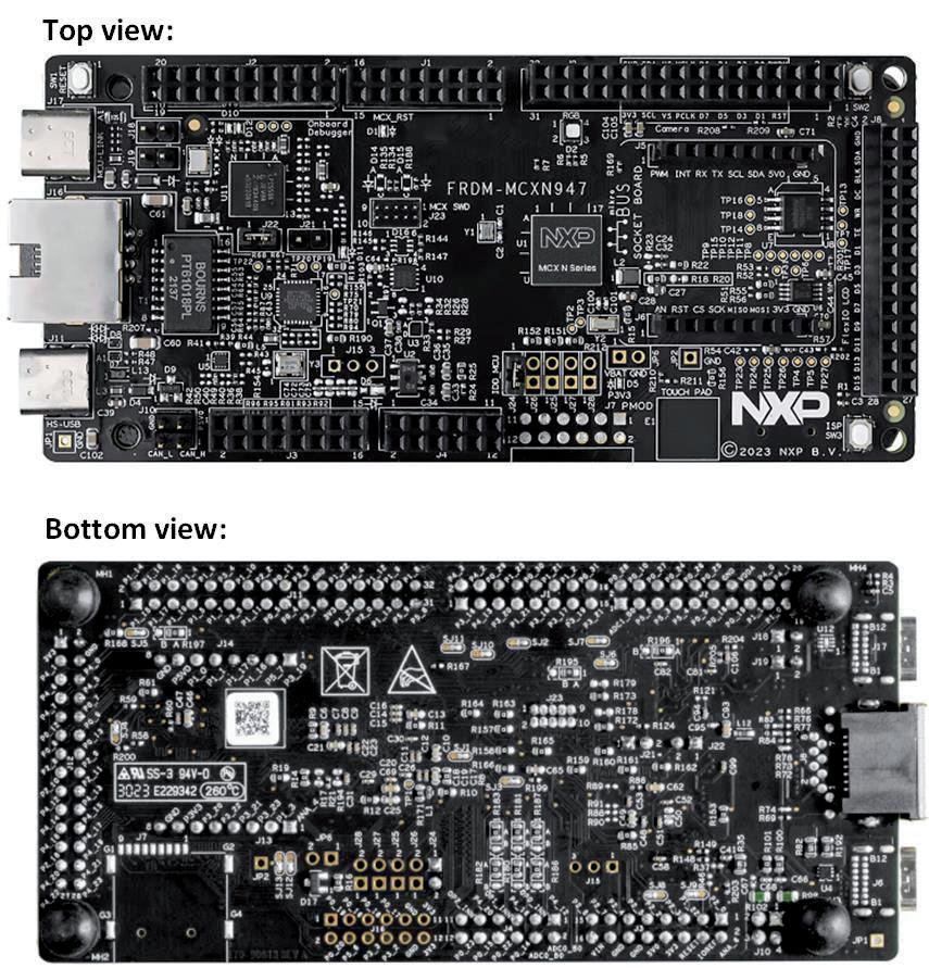
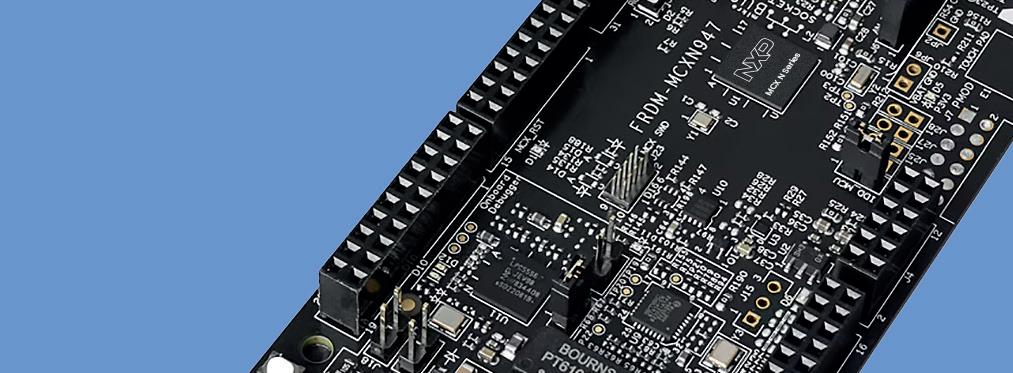
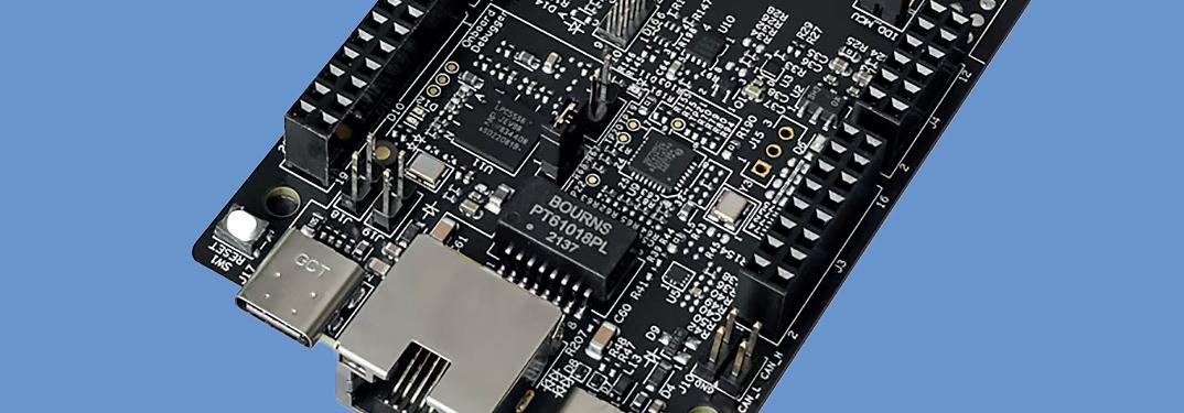
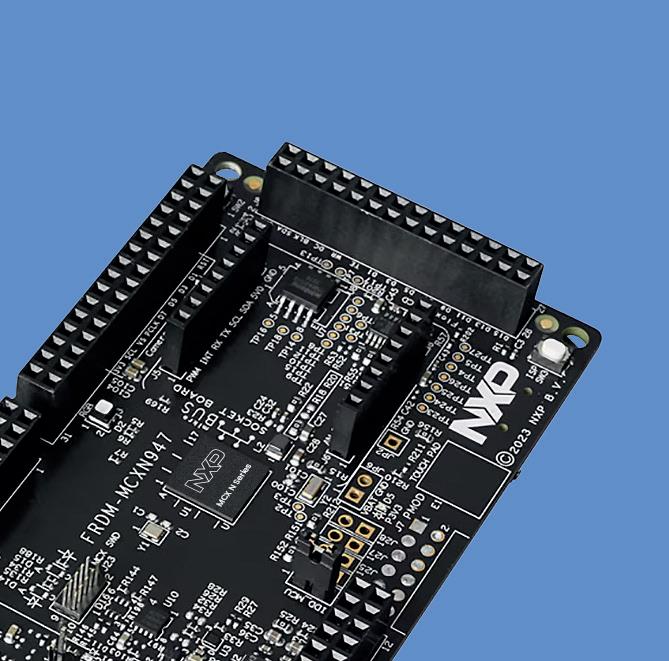
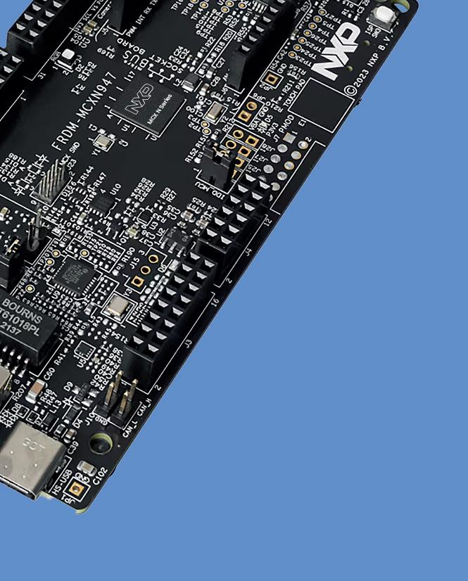
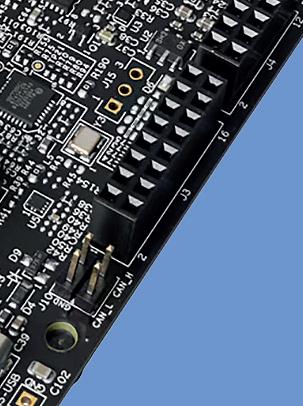
Figure 1.1 shows a close-up picture of the top and bottom views of the development board. A description of the major components on the board is shown in Figure 1.2.
Figure 1.1: The development board.
A block diagram of the development board is shown in Figure 1.3. The basic features of the development board are:
• MCX-N947 Dual Arm 32-bit Cortex-M33 cores at 150 MHz each
• Up to 2 MB dual-bank flash memory
• Neural Processing Unit
• On-board MCU-Link debugger
• SPI/I2C/UART support
• CAN-FD transceiver
• Ethernet controller
• PMOD, mikroBUS, Arduino, DNP, FRDM connectors
• Temperature sensor
• Touchpad
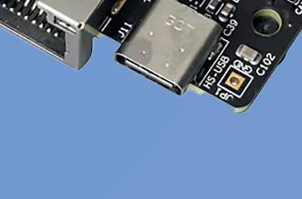
• HS USB Type C connectors
• JTAG/SWD connector
• FlexIO/LCD connector
• SmartDMA/camera connector
• RGB LED
• Reset button
• Wakeup and ISP buttons
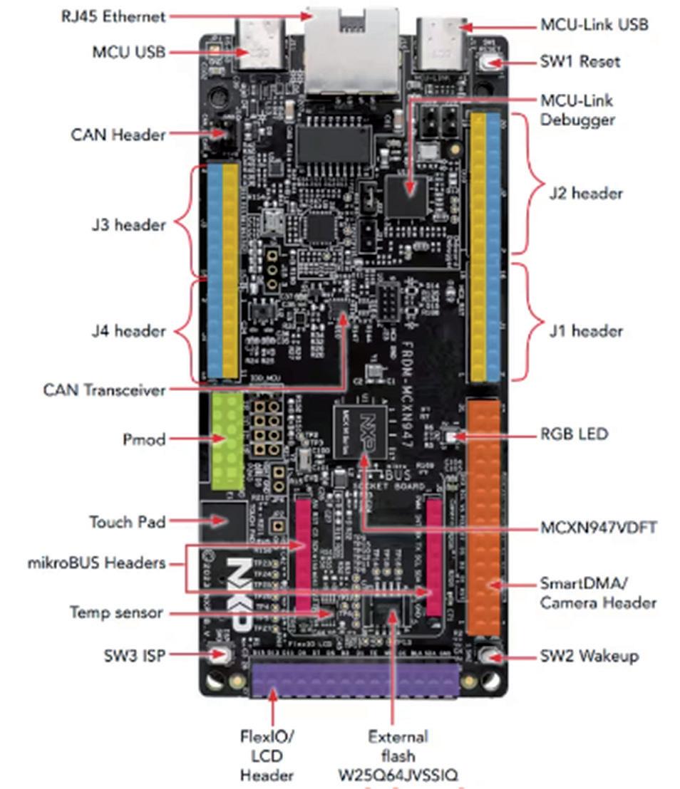
Figure 1.2: Components on the board.
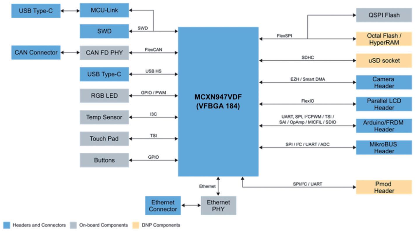
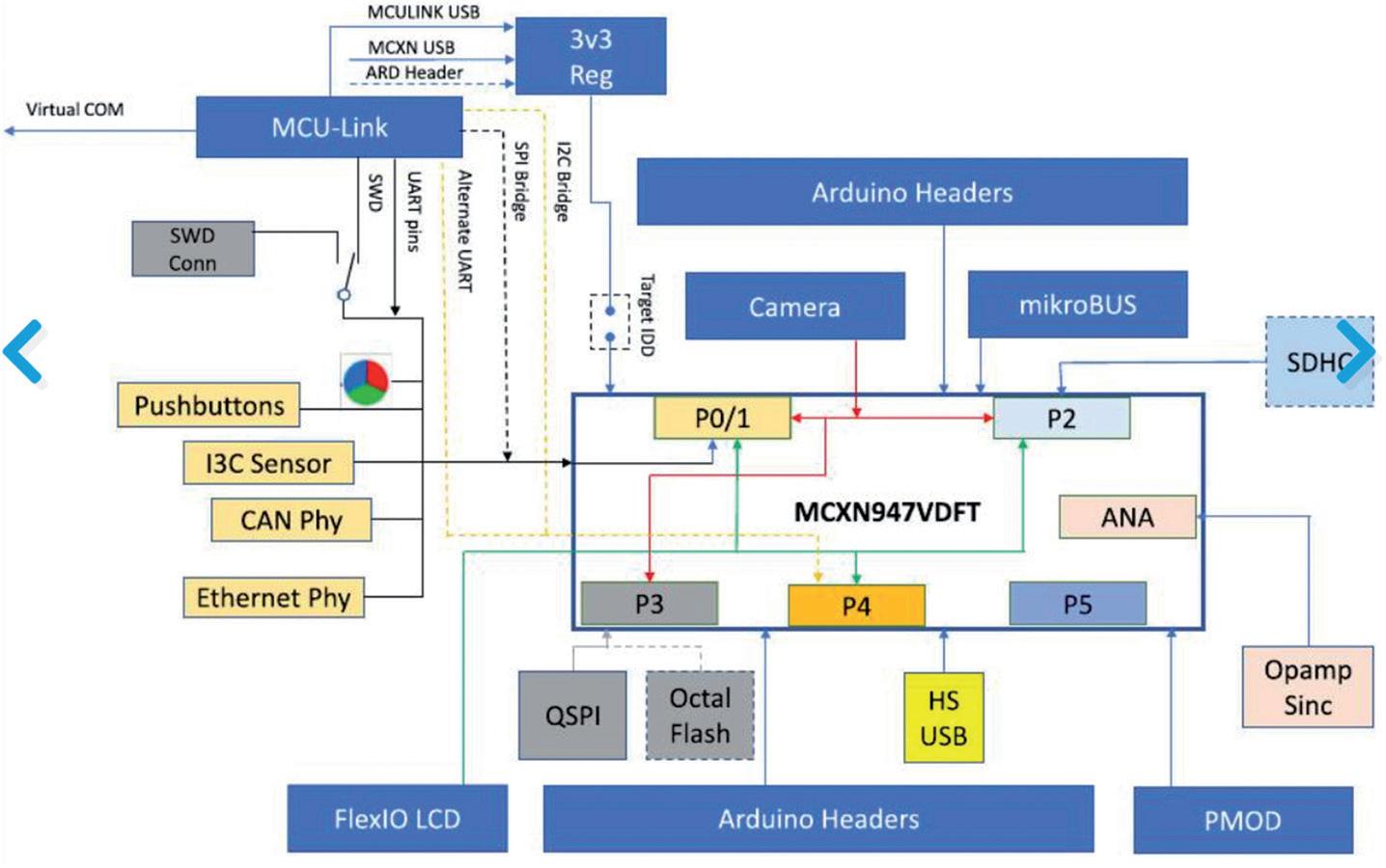
Figure 1.3: Block diagram of the development board.
A more detailed block diagram of the development board is shown in Figure 1.4.
Figure 1.4: Detailed block diagram.
The MCX-N947 Dual Arm Cortex™ M33 microcontroller provides operating performance of 150 MHz. The board is equipped with Flash memory up to 2 MB, optional ECC RAM and external flash memory, which provides adequate capacity for storing data and programs. Additionally, it offers a range of advanced features such as a neural processing unit, PowerQuad, Smart DMA, Micro SD card slot, Ethernet PHY, and HS USB Type-C connectors.
The FRDM-MCXN947 board also has SPI/I2C/UART connectors, WIFI connectors, CAN-FD transceiver, a built-in MCU-Link debugger with CMSIS-DAP and JTAG/SWD connectors. The user interface includes RGB LEDs and Reset, ISP and Wakeup buttons, making it easy to control and monitor the device's operation. Additional tools, such as expansion cards and an Application Code Hub with software samples, are available in the MCUXpresso Developer Experience to support application development and system design using the FRDM-MCXN947 board.
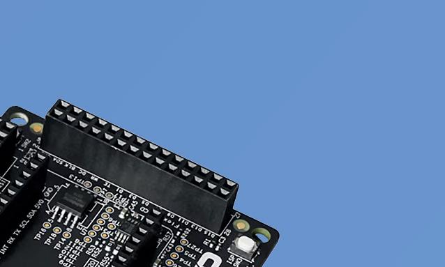
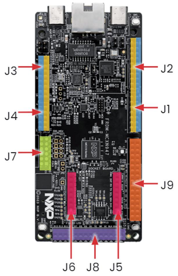
1.2.1 On-board connectors
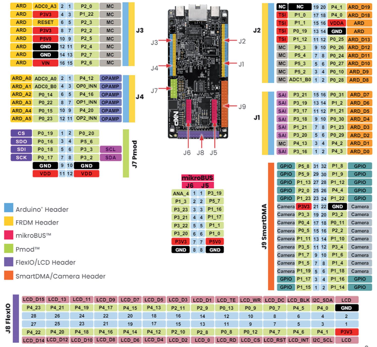
There are 9 connectors on the board with the names J1 to J9. Figure 1.5 shows the layout of the connectors on the board.
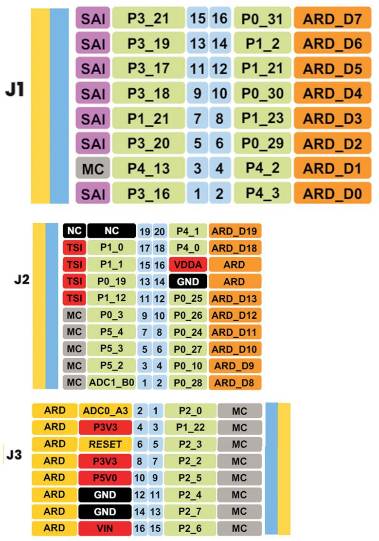
The pin layout of the connectors is shown in Figure 1.6, Figure 1.7, and Figure 1.8
Figure 1.5: On-board connectors.
Figure 1.6: Pin layout of connectors J1, J2 and J3.
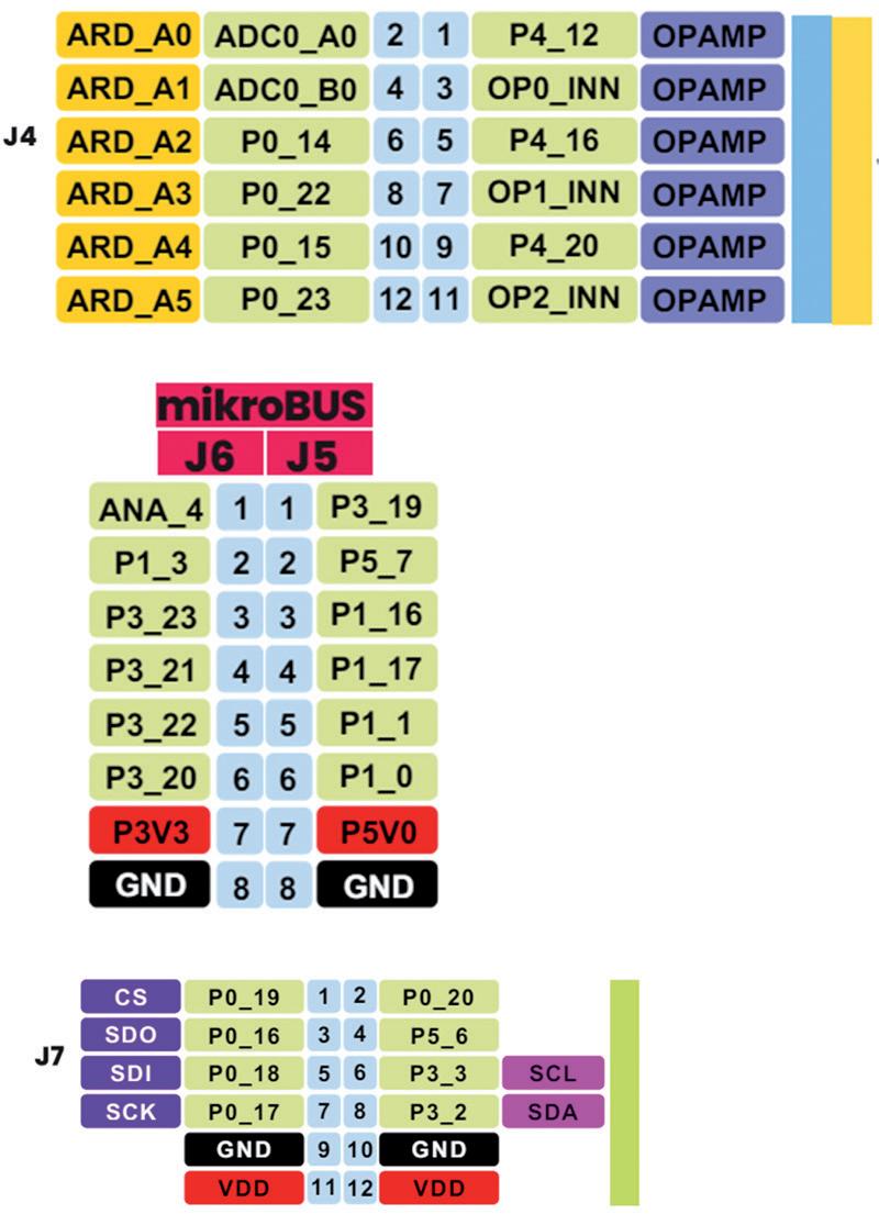
Figure 1.7: Pin layout of connectors J4, J5, J6, and J7.
Figure 1.9 shows the development board and all the connectors in a single figure.
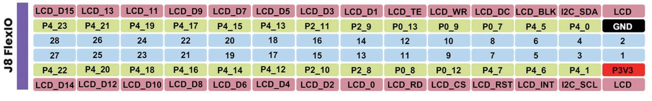
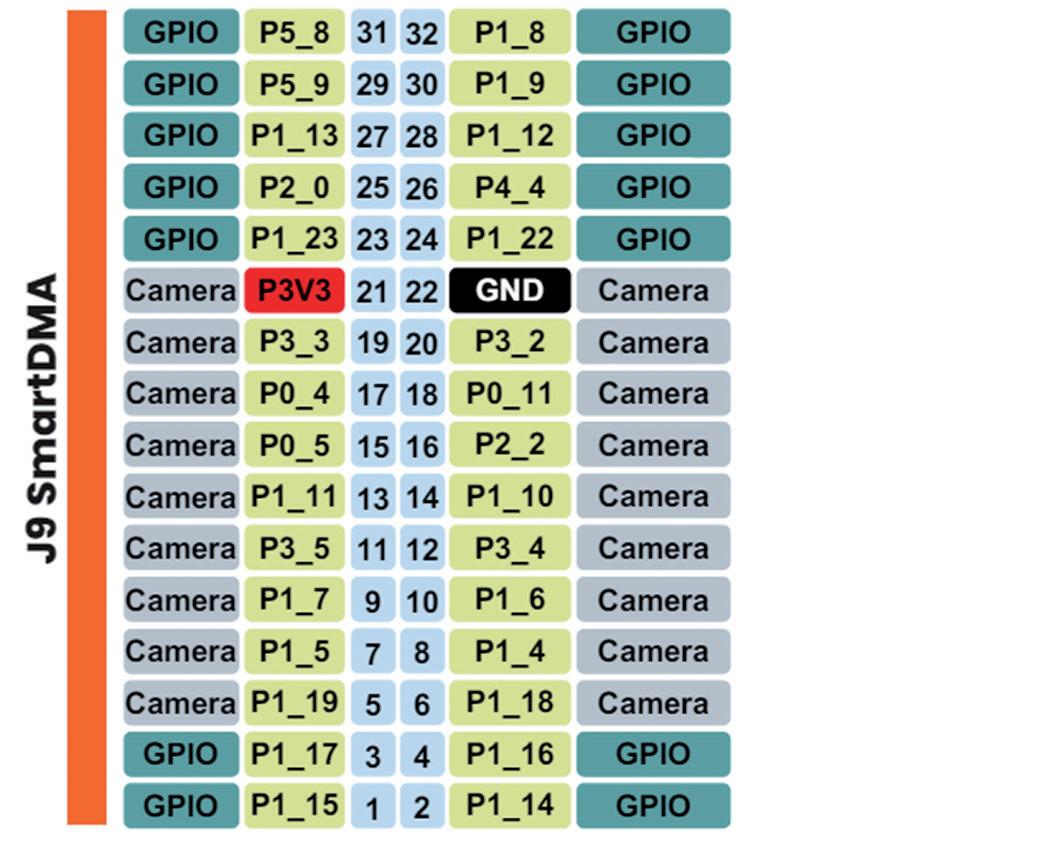
Figure 1.8: Pin layout of connectors J8, J9.
Figure 1.9: The development board and all the connectors.
1.2.2 The MCU
Some important MCU features are (refer to the MCXNx4x Data Sheet for full details):
• 150 MHz operation
• Up to 512 KB RAM
• 16 KB RAM cache
• 4 x 8 KB ECC RAM
• 256 KB ROM
• 2 x 16-bit ADC
• Up to 75 ADC channels
• One integrated temperature sensor per ADC
• 3 high speed comparators
• 2 x 12-bit DAC
• 1 x 14-bt DAC
• Accurate voltage reference
• 3 x operational amplifiers
• 5 x 32-bit general purpose timers
• USB high-speed communication
• DSP accelerator
• Tamper detect
• Neural Processing Unit
• SCTimer/PWM
• LPTimer
• RTC with calendar
• Watchdog timer
• Frequency measurement timer
• 2 x DMA modules
• 10 x LP Flexcomms each support SPI, I2C, UART
• 2 x FlexCAN with FD
• Programmable Logic Unit
• 2 x FlexPWM
• 2 x Quadature encoder
• 1 x Event generator
• SINC filter module
• Digital PDM microphone (connection of up to 4 MEMS microphones)
• Capacitive touch sensor interface
• Up to 124 GPIOs
• Support 1.71 V – 3.6 V I/O supply
• Operating voltage 1.71 V to 3.6 V
• Power-down, deep power-down, and deep sleep modes
• Max I/O current 3 mA
• Output HIGH/LOW current (total for all ports) 100 mA maximum
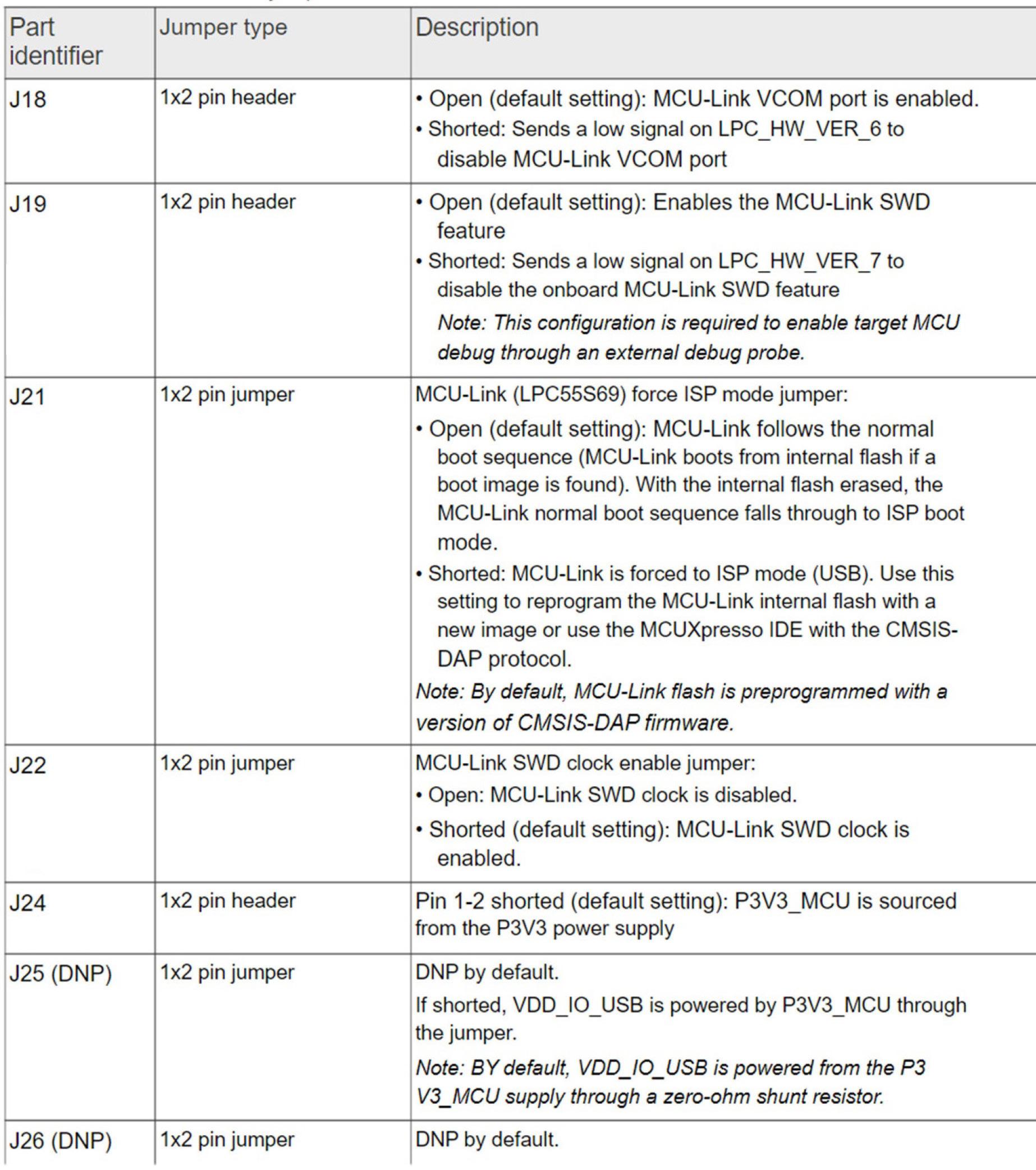
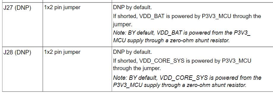
1.2.3 Jumpers on the board
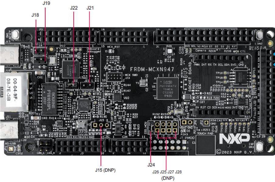
Figure 1.10 shows the jumpers on the development board. The description of these jumpers is given in Table 1.1.
Figure 1.10: Jumpers on the board.
Table 1.1: Jumpers on the board.
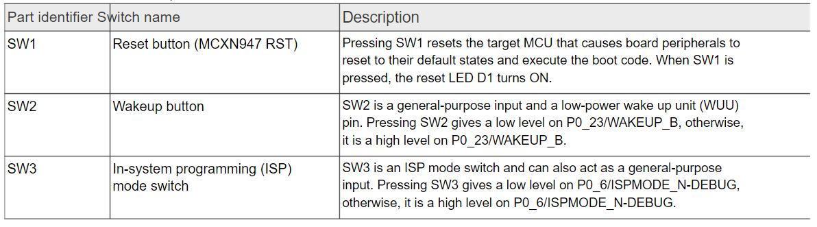
1.2.4 Push buttons on the board
Tactile buttons are populated on the FRDM-MCXN947 development board for human machine interaction (HMI). Each of the buttons has a 0.1 µF bypass capacitor for debouncing and pads for external pull-up resistors. Table 1.2 gives a description of the buttons on the board.
Table 1.2: Buttons on the board.
Reset (SW1): connected to the Reset input of the MCU
Wakeup (SW2): connected to port P0_23
ISP (SW3): connected to P0_6
Touch Pad: connected to P1_3
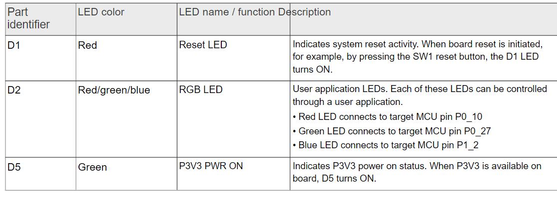
1.2.5 LEDs on the board
There are 3 LEDs on the board as described in Table 1.3.
Table 1.3: LEDs on the board.
RGB LED: Connected in common-cathode mode. i.e. An LED is ON when the corresponding port pin is LOW. Red LED connected to P0_10, Green LED to P0_27, and the Blue LED to P1_2
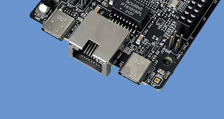
1.2.6 Ethernet interface
On the FRDM-MCXN947 board, the Ethernet controller connects to an RJ45 connector through an Ethernet PHY transceiver. The transmit, receive, and other Ethernet signals are on the P1 port pins. The FRDM-MCXN947 only supports RMII configuration. For this reason, the TXD3 and TXD2 pins of the Ethernet PHY (LAN8741A-EN) have been grounded through resistors R68 and R67, respectively.
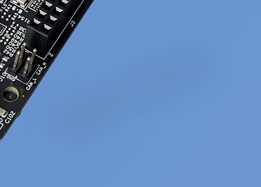
1.2.7 FlexCAN interface
The controller area network (FlexCAN) is a full implementation of the CAN protocol specification, the CAN with flexible data rate (CAN FD) protocol, and the CAN 2.0 version B
protocol, which supports both standard and extended message frames and long payloads. The target MCU (MCXN947) supports two CAN (w/wo FD) controllers (CAN0 to CAN1).
On FRDM-MCXN947, only the CAN0 controller is used. The CAN0 controller connects to a 4-pin CAN header through a CAN transceiver (TJA1057GTK/3Z). The CAN0_TXD and CAN0_RXD signals are through ports P1_10 and P1_11, respectively.
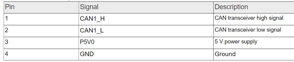
Jumper J10 is a 4-pin CAN header. It is connected to the CAN0 bus and allows external connection with the bus. Table 1.4 shows the CAN header pin layout.
Table 1.4: CAN header pin layout.
1.2.8 I3C sensor interface
The FRDM-MCXN947 board includes one P3T1755DP digital temperature sensor to demonstrate the I3C capabilities of the target MCU. This sensor device allows for 32 I3C provisional IDs, supports the full operating voltage of the board, programmable overtemperature alerts, 12b resolution, and has an accuracy of ±0.5 °C (maximum) from –20 °C to +85 °C.
The 7-bit I2C address of the sensor device is 0b1001000 (0x48). The sensor device connects to the I3C1 controller of the device through P1_[16:17] Port, where P1_16 is the SDA and P1_17 is the SCL pins. 4.7 kΩ internal pull-up resistors are provided for the I3C bus.
1.2.9 SD card interface
On the FRDM-MCXN947 board, the uSDHC controller connects to the SD card connector (J12) (not populated by default). The SD card detect pin is an open switch that shorts with GND when the card is inserted. The interface pins are:
DET: P2_1
DAT1: P2_2
DAT0: P2_3
CLK: P2_4
CMD: P2_5
CD/DAT3: P2_6
DAT2: P2_7
1.3 Starting Up – demo program
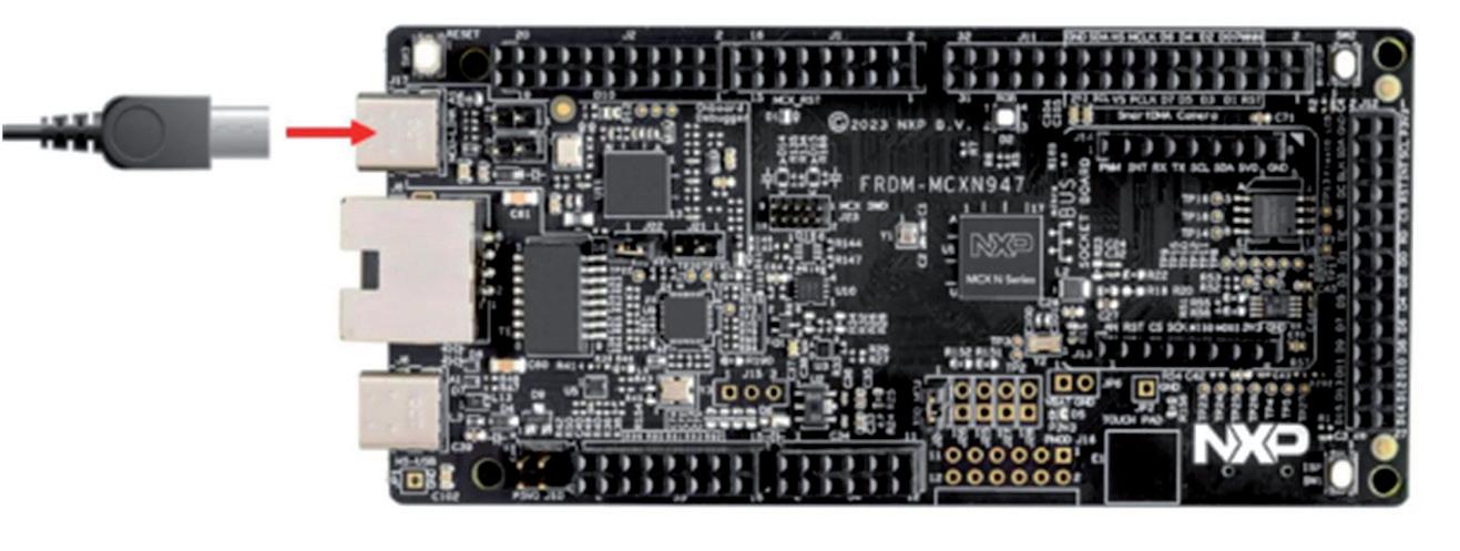
A demo program has been pre-loaded into the memory of the development board for testing purposes. Connect a type-C USB cable from connector J17 (see Figure 1.11) to a host computer or power supply to power up the board and run the demo program. You should see the RGB LED blinking at a steady rhythm.
1.4 MCX N Series microcontrollers
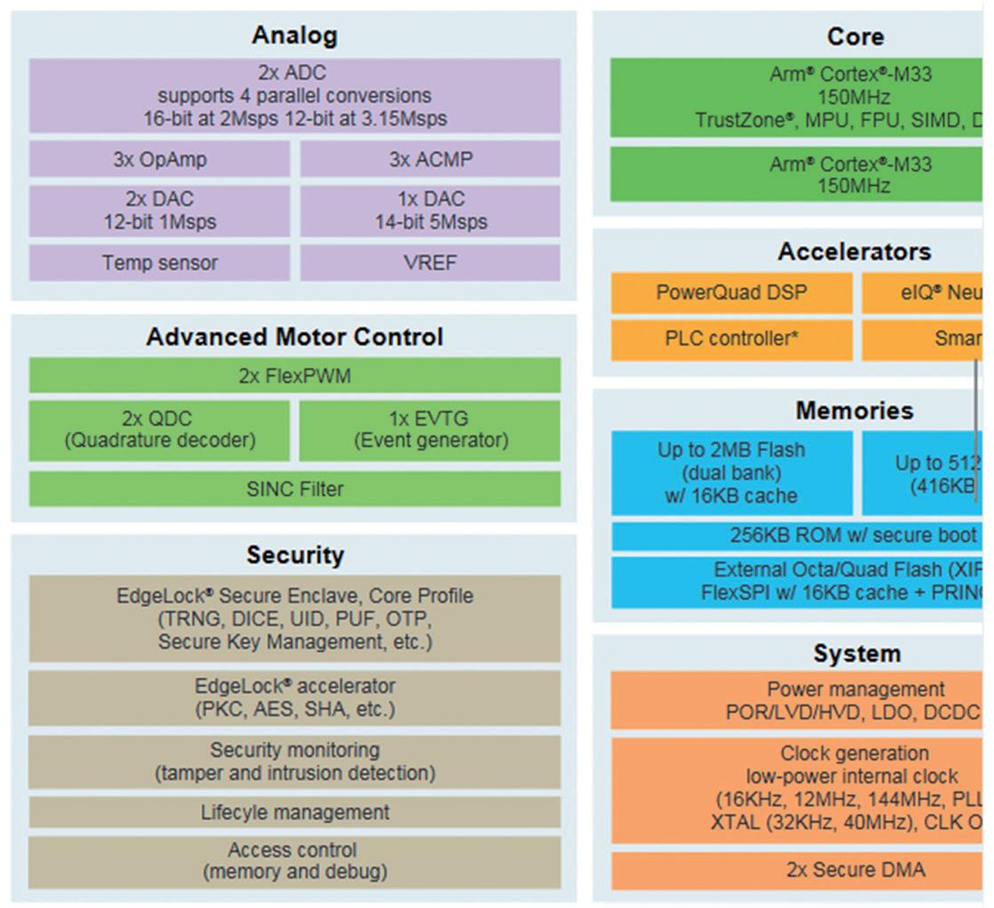
MCX N series of microcontrollers are highly integrated, low-power MCUs designed with intelligent peripherals and on-chip accelerators that provide the ultimate balance of performance and energy consumption. They are based on the dual Arm Cortex-M33 core operating up to 150 MHz. Table 1.12 shows the basic features of the MCX N series of microcontrollers.
Figure 1.11: Running the demo program.
Figure 1.12: MCX N series features.
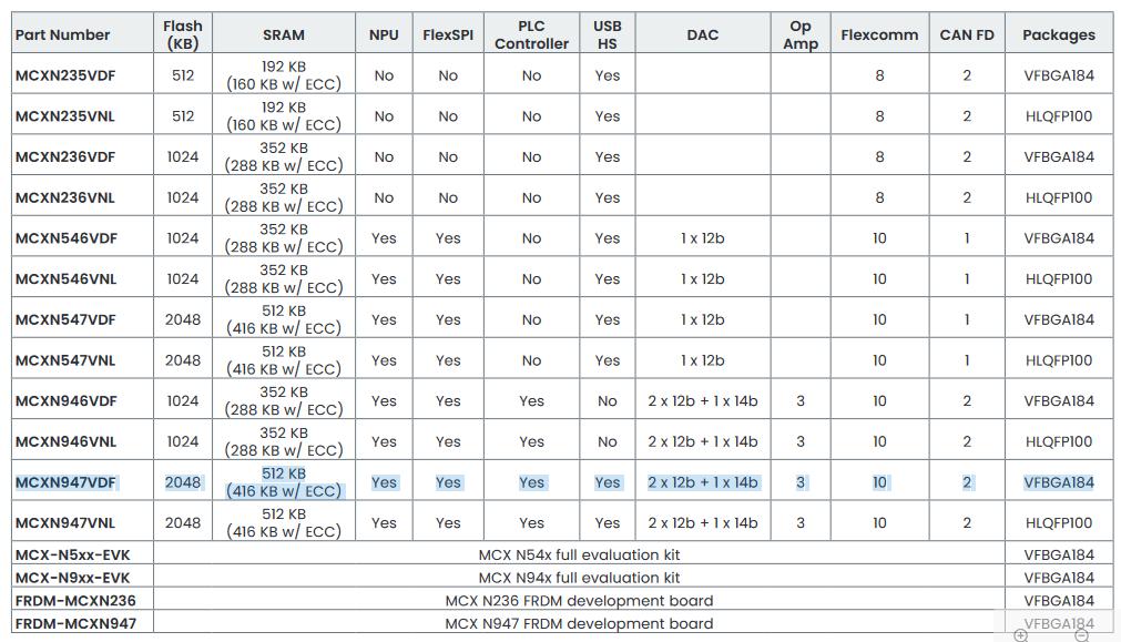
Table 1.5 shows the basic specifications of all the MCUs in the MCX N series of microcontrollers. The one used in this book is highlighted for comparison purposes.
Table 1.5: MCX N series of microcontrollers.
Chapter 2 • MCUXpresso and the Software Development Kit (SDK)
2.1 Overview
In this book we will be using the MCUXpresso SDK and the IDE for developing projects using the development board. MCUXpresso IDE is an Eclipse based development environment for NXP MCUs using Cortex-M cores. It supports many processors, including the MCXN947, the i.MX RT, LPC and Kinetis devices, devices from Cortex-M0+ to most of the Cortex family of processors. The SDK and the IDE must be installed before they can be used.
2.2 Installing the MCUXpresso IDE and SDK
The steps to install the MCUXpresso SDK and IDE are given below:
• Go to following web site: https://www.nxp.com/document/guide/getting-started-with-frdm-mcxn947:GSFRDM-MCXNXX?section=get-software
• Click on GET MCUXPRESSO IDE (Figure 2.1)
Figure 2.1: Click on the link.
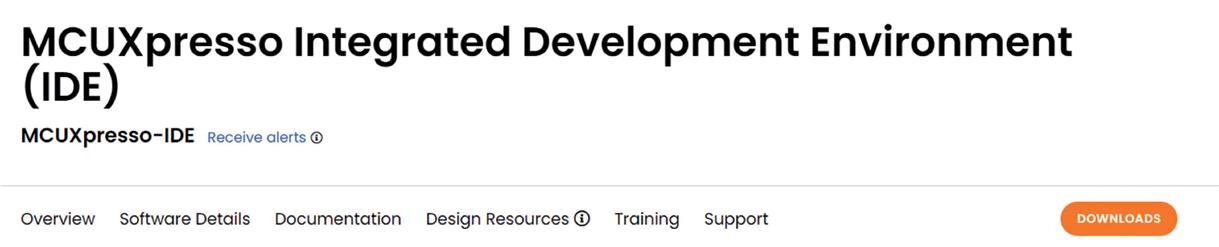
• Click DOWNLOADS (Figure 2.2)
Figure 2.2: Click Downloads.
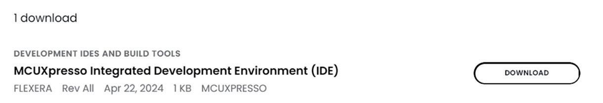
• Click to Download the MCUXPRESSO IDE (Figure 2.3)
Figure 2.3: Click to Download.
• You will have to create an account and login to the NXP site.
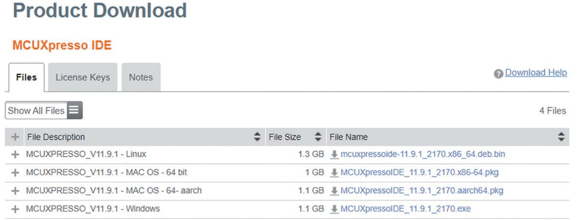
• Select your operating system and click to download the file (Figure 2.4). At the time of drafting the book the file was named: MCUXpressoIDE_11.9.1_2170. exe
Figure 2.4: Select your operating system and download.
• Click on the file to install the IDE.
• Click to start the IDE and give a workspace name.
• Click Launch.
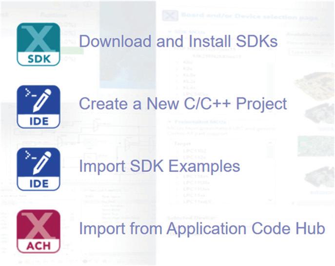
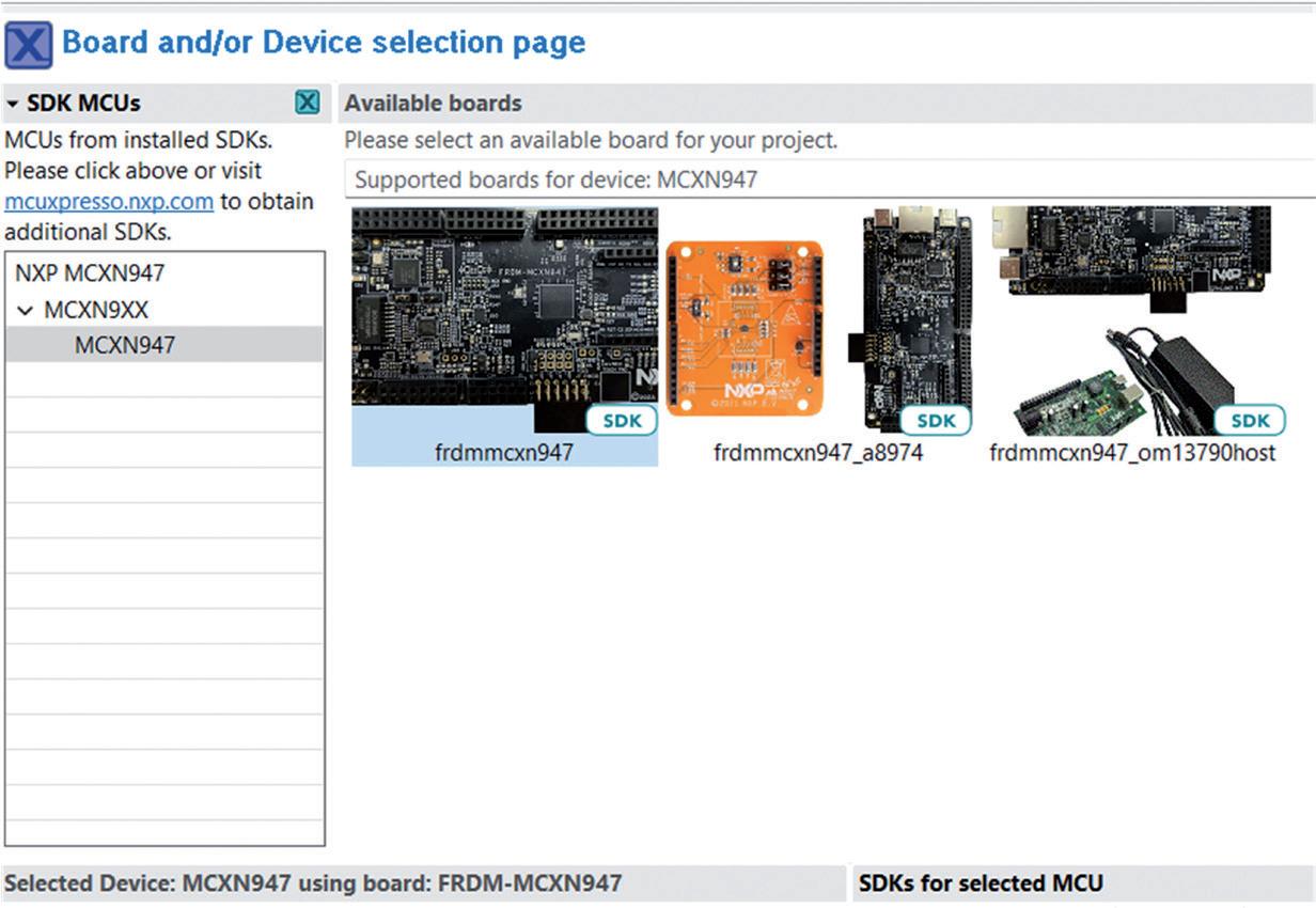
• Click Download and Install SDKs (Figure 2.5).
Figure 2.5: Install SDKs.
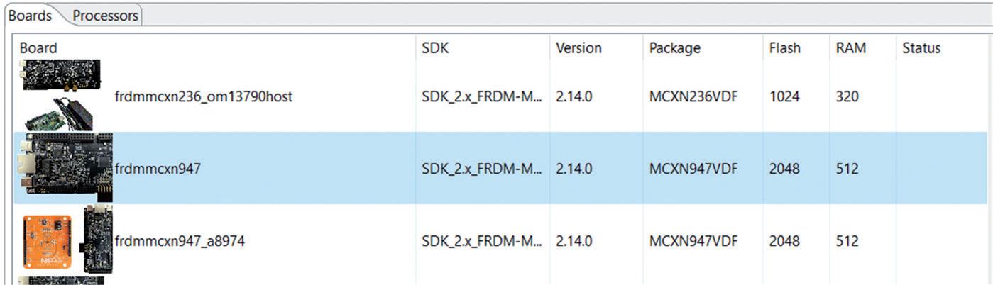
• Select board frdmmcxn947 (Figure 2.6)
Figure 2.6: Select frdmmcxn947.
• Click Install and Import Examples
This completes the installation of the MCUXpresso IDE
2.3 Testing the installation
Now that the installation is complete, you should check the installation by compiling and running one of the demo programs supplied. Here, you will compile and run the demo example called led_blinky which flashes the on-board LED. The steps are as follows:
• Start the MCUXpresso IDE.
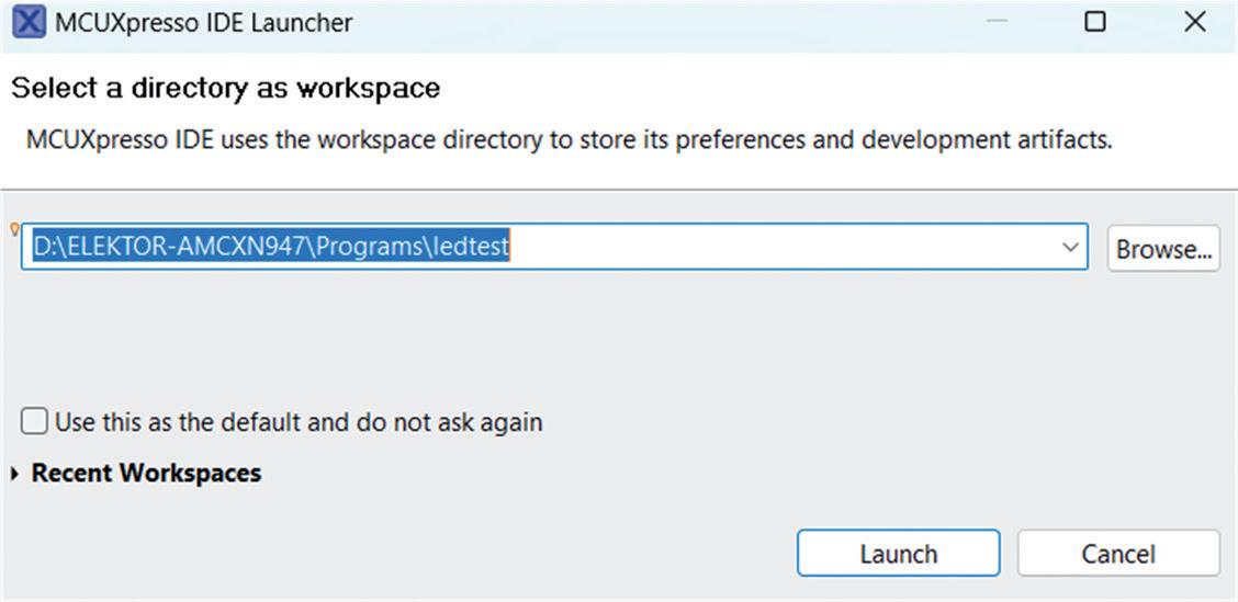
• Create Workspace ledtest (Figure 2.7) and click Launch.
Figure 2.7: Create the ledtest workspace.
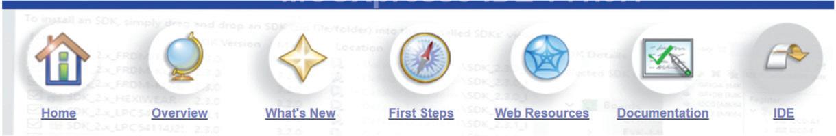
• Click IDE to be in IDE mode (Figure 2.8).
Figure 2.8: Click IDE.
• Click Import SDK Example(s)… under the MCUXpresso IDE – Quickstart Panel.
• Click to select board frdmmcxn947 (Figure 2.9). Click Next.
Figure 2.9: Select board frdmmcxn947.
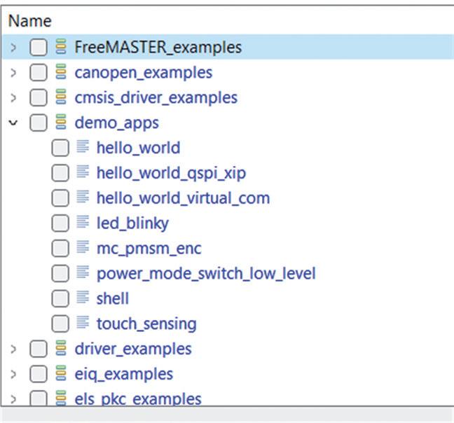
• Click to expand demo_apps (Figure 2.10).
Figure 2.10: Expand demo_apps.
• Click to select led_blinky and click Finish.
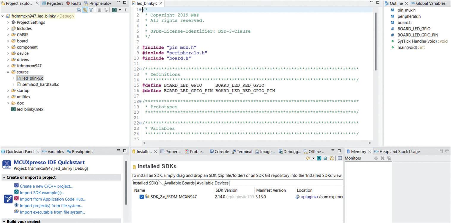
• You should see the File Explorer at the left window, the program code in the middle window, the header filenames and functions used at the righthand window, and the console terminal etc at the bottom of the window (Figure 2.11). Do not worry if you do not understand how the program works at this stage!
Figure 2.11: The IDE window.
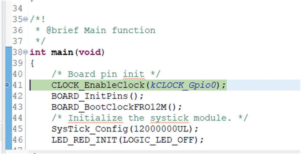
• The program code listing is shown in Figure 2.12.
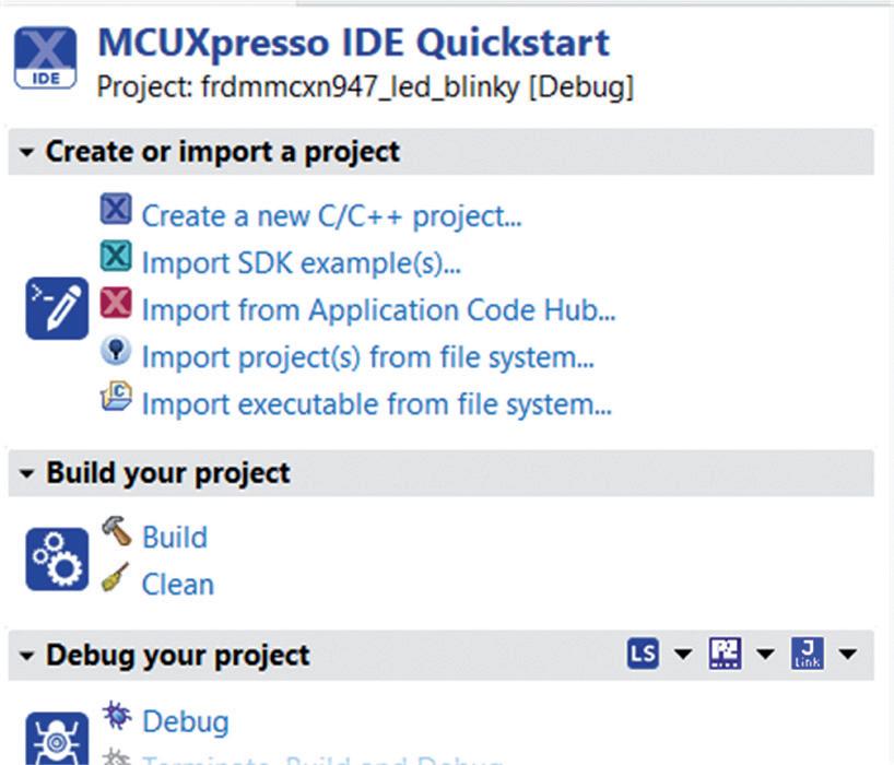
• Click Debug under MCUXpresso IDE Quickstart at the left bottom of the screen (Figure 2.13) to compile and run the program in debug mode.
Figure 2.13: click Debug.
• Accept the presented Debug Probe.
• The program will compile and stop with the cursor highlighted as a horizontal bar on the first executable code (Figure 2.14).
Figure 2.14: Program compiled and in debug mode.
• Connect your development board to the USB port of your PC. The red power LED should come ON.
• Click Run -> Resume to load the program to the development board and then run it. You should see the red LED flashing during the loading process.
• The LED should flash as before.
• Click Run -> Terminate to terminate the debug session.
• Change the number in statement SysTick_Config to 1200000UL.
• Click Debug to compile and run the program again. You should see the LED flashing at a much faster rate. This proves that the Ide has been installed correctly and we can load programs to the development board.
• Click Run -> Terminate to terminate the debug session.
2.3.1 Some information on the program
The original program generates interrupts at second and then the state of the LED is toggled inside the interrupt handler. Notice that at the beginning of the program the following header files are included:
#include "pin_mux.h"
#include "peripherals.h"
#include "board.h"
You can right click on the file names at the right-hand side of the window and display the contents of these files if you wish. File pin_mux.h stores the I/O direction definitions. File
board.h stores the board name, debug and UART configurations, on-board accelerator configurations, user LED configurations, user Button configuration and other configurations. Here we are interested in the user LED configurations which are defined as follows:
#define BOARD_LED_GPIO BOARD_LED_RED_GPIO
#define BOARD_LED_GPIO_PIN BOARD_LED_RED_GPIO_PIN
Function GPIO_PortToggle() toggles the state of the port pin, in this case the LED. SysTick_Handler() is called every second and it is here that the state of the LED is toggled. Function SysTick_Config() initializes the system timer and its interrupt. Here, the timer interrupts occur at every 12,000,000 ticks which correspond to one second with the 12 MHz clock set by the statement BOARD_BootClockFRO12M(). The system timer is in free running mode and generates periodic interrupts. Its only argument is the number of ticks between two interrupts.
The GPIO ports must be configured before they can be used (e.g. the input or output mode, default state, analog or digital, etc). This is normally done in files pin_mux.c and pi_mux.h in folder board. This configuration is already done for the on-board LED. You will learn in the hardware projects chapter of the book how to configure the GPIO ports using the ConfigTools menu option of MCUXpresso IDE.
Some other GPIO related functions supported by the SDK are (see web link: https:// mcuxpresso.nxp.com/api_doc/dev/1393/a00123.html):
• Initialize a GPIO pin used by the board: GPIO_PinInit()
• Set the output level of the multiple GPIO pins to the logic 1 or 0: GPIO_ PinWrite()
• Set the output level of the multiple GPIO pins to the logic 1: GPIO_PortSet()
• Set the output level of the multiple GPIO pins to the logic 0: GPIO_Port_ Clear()
• Reverse the current output logic of the multiple GPIO pins: GPIO_ PortToggle()
• Read the current input value of the GPIO port: GPIO_PinRead()
MCUXpresso IDE is an immensely powerful IDE supporting many features. Interested readers can download the 293-page user guide: MCUXpresso IDE User Guide, Rev. 11.7.1 – 28 March 2023 from the NXP web site.
2.3.2 Modified program
The program given in Figure 2.12 runs in the timer interrupt handler function. i.e. the LED is toggled inside the timer interrupt handler function. A modified program (led_on_board) is shown in Figure 2.15 where the LED is toggled inside the main program, but the timer interrupt is configured for 1 ms interrupts and time delay is used inside the main program based on timer interrupt counts. Function SysTick_DelayMs(n) delays the program by n milliseconds. Notice also that the GPIO_PinWrite() function is used to set and reset the port pins. In this program the LED flashing time is set to 50 ms.
This book is about the use of the FRDM-MCXN947 Development Board, developed by NXP Semiconductors. It integrates the dual Arm® Cortex®-M33, operating at up to 150 MHz. Ideal for Industrial, IoT, and machine learning applications. It features Hi-Speed USB, CAN 2.0, I3C and 10/100 Ethernet. The board includes an on-board MCU-Link debugger, FlexI/O for LCD control, and dual-bank flash for read-while-write operations, supporting large external serial memory configurations.
One of the important features of the development board is that it features an integrated eIQ® Neutron Neural Processing Unit (NPU), thus enabling users to develop AI-based projects. The development board also supports Arduino UNO form factor header pins, making it compatible with many Arduino shields, mikroBUS connector for MikroElektronika Click Boards, and Pmod connector.
One of the nice things of the FRDM-MCXN947 development board is that it includes several on-board debug probes, allowing programmers to debug their programs by communicating directly with the MCU. With the help of the debugger, programmers can single-step through a program, insert breakpoints, view and modify variables and so on.
About the Author
Many working and tested projects have been developed in the book using the popular MCUXpresso IDE and the SDK with various sensors and actuators. Use of the popular CMSIS-DSP library is also
Prof. Dr. Dogan Ibrahim holds a BSc in Electronic Engineering, an MSc in Automatic Control Engineering, and a PhD in Digital Signal Processing. Dogan has worked in many industrial organizations before returning to academic life. Prof. Ibrahim is the author of over 60 technical books and more than 200 technical articles on microcontrollers, microprocessors, and related fields. He is a Chartered Electrical Engineer and a Fellow of the Institution of Engineering Technology.
The projects provided in the book can be used without any
modifications in many applications. Alternatively, readers can base their projects on those given in the book during the development of explained with several commonly used matrix operations.