1 1 I Innttrroodduuccttiioon n
If you watch one of the early James Bond movies with Sean Connery, the villain's lab usually has a computer with a front panel covered in flashing lights. For a theater play at their school, three fifteen-year-old students with no knowledge of electronics were once asked to build such a "computer" as a prop for the play. However, that is easier said than done: two hours of turning on and off switches mounted on a board at the speed of blinking lights can throw your arm off! A roller, driven by an electric motor with cams or pins that raise and lower switch contacts to open and close circuits? Not the last word in wisdom either! How nice it would be to have an electronic "universal tool", with which control tasks of any kind would be simple even for a layman! In the form of the microcontroller, this universal tool has existed for some time, but its use was too difficult for the layman due to the relatively complex inner workings. To be able to use a microcontroller, one had to deal with a data sheet of several hundred pages (see bibliography [7]) and be as well versed in electronic circuitry as in at least one programming language. The many powerful function blocks inside the microcontroller are controlled by so-called registers (see section 3.2 and bibliography [7]), which determine, for example, the data direction of inputs and outputs or the clock frequency of timers.
Such and similar problems might have given Italian professor Massimo Banzi and his friends the idea of making the use of microcontrollers accessible to a wide circle of interested but electronically largely clueless people while having a birra or vino at their regular "Arduino" pub in Ivrea, Italy. They developed a series of standardized microcontroller boards and an associated Integrated Development Environment (IDE). This IDE offers all the tools from the editor for creating the source code, through the compiler for translating the source program into the machine code of the microcontroller, to the bootloader for transferring the machine code into the microcontroller (see Figure 11). Thanks to the inexpensive Arduino® boards, even laymen now can realize their electronic ideas, especially since the Arduino IDE can be downloaded free of charge from the Internet to the user's PC.
The associated software is developed by the user with the Arduino IDE, which is based on the GCC (GNU C Compiler) from the GNU Compiler Collection, a very powerful compiler for the programming languages C and
Microcontrollers Hands-On Course for Arduino Starters 10
C++. The Arduino IDE thus provides a trained programmer with the full power of a C and C++ compiler. However, working with this compiler, which is quite complex due to its performance, is very demanding for a beginner, to put it mildly. So that the layman does not have to deal with topics such as the above-mentioned registers for controlling the microcontroller internals and does not have to delve too deeply into the world of C programming. The team around Massimo Banzi has created encapsulated program parts, so-called functions, and integrated them into the Arduino IDE, which complete these tasks for the beginner. With the help of these functions, the user only has to explain that, for example, the pin of the microcontroller with the number 3 should be an input, because a switch is connected to it, and pin 8 should be configured as an output, because it is connected to a light-emitting diode. The function then carries out all the necessary register settings on the chip of the microcontroller in the background, unnoticed by the user, to realize the expected property of the pin.
Many Arduino®-compatible accessory circuits with sensors, motors, displays, etc. are now available on the electronics market. When using the Arduino IDE, extensive libraries (see chapter 3.13) are available to the user for controlling them. The user only has to integrate the corresponding library into his program and then has all the tools he needs to control an object in his project.
In the following chapters, we will acquire all the hardware and software knowledge we need to implement our own Arduino projects, then deepen our knowledge and test our creativity with many exercises. As we will see in several exercises, it is easy with the Arduino system, for example, to make lights flash as in the above task for the theater play.
For a master carpenter without any electronic training, it was easy to implement and realize his own project ideas with the help of the Arduino concept after only a short training period. Moreover, even artists, who are often said not to have a great affinity for scientific subjects, use Arduino components for their light and sound installations.
Introduction 11
2 2 T Thhe e H Haarrddwwaarre e B Baassiiccs s
The central topic of our beginners' course is the microcontroller, a universal component for controlling electronic devices.
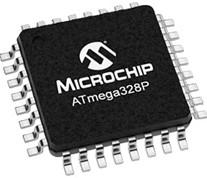
To work with a microcontroller, we need the corresponding hardware, namely a microcontroller system consisting of the integrated microcontroller circuit shown in Figure 1, which is soldered onto a board together with some components required for the input and output of data.

In this chapter, we will look at the features of a microcontroller and we will get to know the Elektor Arduino Nano Training Board MCCAB on which we will do our exercises.
2.1 The Electronic Processing of Data and Signals
The world we live in is an analog world: between two colors, there are an infinite number of other colors, between two tones there are an infinite number of intermediate frequencies and between two temperatures, there are an infinite number of other temperature values.
In our analog world, we have various tools at our disposal for performing calculations: the abacus has been in use for many millennia, with which not only the four basic arithmetic operations of addition, subtraction, multiplication and division can be performed, but also root extraction. Mechanical calculating machines were available from the late Middle Ages onwards. For many older technicians, the slide rule is still a familiar term, which primarily enables rapid multiplication and division through the graphic addition of logarithms.
In electronics, analog voltages can be added, subtracted, multiplied, divided, squared, integrated and differentiated with the help of operational amplifiers and special integrated analog computing circuits.
In analog technology, the electromechanical pointer instrument shown on the left in Figure 2, oscilloscopes and X-Y recorders are available for carrying out measurements.
Microcontrollers Hands-On Course for Arduino Starters 12
Figure 1: The ATmega328P Microcontroller
In the analog pointer instrument on the left in Figure 2, the deflection of the pointer is proportional to the applied voltage, so the pointer can continuously display any value within the measuring range. However, the theoretically unlimited accuracy of analog pointer instruments, due to the stepless display, is limited just like that of the other analog measuring instruments mentioned above, e.g., by manufacturing tolerances, their mechanical construction, their internal resistance, friction and conduction losses, reading inaccuracy (parallax) etc. Reducing errors to 1% or less can only be achieved with great effort. In addition, analog measuring instruments are sensitive to electromagnetic interferences, excessive noise and temperature fluctuations.
The digital measuring device on the right in Figure 2 displays the measurement result directly as a numerical value. Accuracy limitations due to mechanical influences or derivation errors are thus eliminated. To be able to display an analog voltage or a temperature value on a digital instrument, for example, it is necessary to convert the physical analog value into a numerical value that the display of the measuring instrument can show. This task is performed by the analog/digital converter (ADC) described in section 2.7.2.1, which quantizes the analog signal, i.e., divides it into steps of a certain size. The ADC measures the current voltage value at its analog input at a certain point in time and converts it into a numerical value Z corresponding to the voltage level. The smaller the quantization steps are chosen, the better the numerical values approximate the actual course of the input signal, as shown in Figure 3 and Figure 4.

The digital measuring instrument on the right in Figure 2 is not subject to any mechanical influences or reading errors, but due to the quantization by the analog/digital converter, it is only able to display results in steps of

2.1 The Electronic Processing of Data and Signals 13
Figure 2: Analog and digital panel meter (source: Conrad Electronic SE, Hirschau)
one decimal place after the decimal point. The theoretically infinite number of values between two digit steps of the least significant digit cannot be displayed; they are omitted.


As can be seen from Figure 3 and Figure 4, the resolution of a digital measuring device can be increased to a (theoretically) infinite number of decimal places by means of increasingly finer quantization. The "built-in" analog/digital converters of common microcontrollers quantize the analog input signal with 256 to 4096 steps (this corresponds to a resolution of 8 ... 12 bits, see the following section 2.7.2.1), special integrated ADC circuits convert with 65536 (corresponding to 16 bits) and more steps.
With a measuring range of 5 volts, 65536 steps lead to a resolution of
Microcontrollers Hands-On Course for Arduino Starters 14
Figure 3: Analog/Digital Conversion with four quantization stages
Figure 4: Analog/Digital Conversion with sixteen quantization stages
V V 0,000076 65536 5 for one quantization
analog signal V(t) quantised signal Z V(t), Z analog signal V(t) quantised signal Z V(t), Z
stage.
The transmission paths of digital signals are also far more immune to interference than those of analog signals are. While analog measuring lines usually have to be shielded to protect them against external influences such as noise and electromagnetic interference, this is usually not necessary with digital signals, because, as we will see below, they only transmit the states "voltage present" or "voltage absent".
2.1.1 Signal States and Numbers in Digital Technology
Digital systems are "binary" systems (Latin bina "double, paired"), because they only know the two states logical 0 and logical 1 corresponding to "voltage present" or "voltage not present". A logical 0 is also called a LOW signal (low voltage) and a logical 1 a HIGH signal (high voltage). This principle can be realized very easily with a switch that can be either open or closed. The value 0 is assigned to the open switch and the value 1 to the closed switch.
Digital circuits, of course, use no mechanical switches but corresponding switching transistors.
As can be seen in Figure 5, one switch or switching transistor can assume two different states and thus form the two binary numerical values 0 and 1. If the number of switches is increased, the number of possible state combinations is also increased. In this way, it is possible to build binary numbers of any size consisting of zeros and ones with the corresponding number of switches. The following Figure 6 shows the combinations possible with 2 switches.
2.1 The Electronic Processing of Data and Signals 15
Figure 5: Possible states of one switch and binary values assigned to the states
5 V S = 0 switch open switch closed 5 V S = 1
Certain quantities of binary numbers have been given their own designations:
One digit of a binary number is called a "Bit" .
A binary number consisting of 4 bits is called a "Nibble" .
A binary number consisting of 8 bits is called a "Byte" .
Example:
With a set of N bits, 2N combinations can be formed and thus 2N different natural number values are possible.
The largest numerical value that can be represented with N bits is 2N – 1 (since the series begins with 0).
Example:
With 1 byte = 8 bits (i.e., N = 8), 28 = 256 different dual numbers between 0000 0000 ... 1111 1111, thus, the numerical values 0 ... (28 – 1) = 0 ... 255 can be implemented.
Microcontrollers Hands-On Course for Arduino Starters 16 Switch states Binary number Decimal number 0 0 0 0 1 1 1 0 2 1 1 3
Figure 6: Possible state combinations of two switches and the assigned binary and decimal values
1 0 1 1 0 0 1 1 Bits Nibble Nibble Byte
With 2 bytes = 16 bits (N = 16), 216 = 65536 different dual numbers, i.e., the numerical values
0 ... (216 – 1) = 0 ... 65535 can be realized.
2.1.2 Data Processing "digital" instead of "analog"
Considering the achievable accuracy, the lack of mechanics and the largely insensitivity to external influences of digital circuits, it is no wonder that the triumph of digital technology began with the appearance of the first integrated logic, counter and arithmetic circuits – such as the TTL family 74xxx or the CMOS series CD4xxx.
To be able to digitally process the variables of our analog world, they must be recorded by corresponding sensors, converted into a digital numerical value, digitally processed by a controller and then converted back into an analog signal and output. Figure 7 shows the process using the example of a digital temperature control.
The resistance R on the left in Figure 7 is temperature-dependent. Its resistance value decreases with rising temperature and increases with falling temperature. Together with the resistor RV, R forms a voltage divider for the reference voltage VREF. The voltage divider consisting of RV and R thus changes the analog input voltage of the analog/digital converter (ADC) according to the current temperature. The digital value corresponding to the temperature is available at the output of the ADC.
The controller processes this digital value according to its program. The result of the processing is output via the digital/analog converter (DAC) to the driver stage V, the output power of which, for example, heats up an
2.1 The Electronic Processing of Data and Signals 17
Figure 7: Example of digital control of analog variables
VREF Processing R RV ADC DAC V Controller RH D A D A
oven – symbolized in Figure 7 by the heating resistor RH – accordingly. The controller that takes over the processing of the digital signals in Figure 7 is nowadays usually a microcontroller.
2.2 What is a Microprocessor?
The availability of the first integrated digital circuits – for example, from the TTL family 74xxx or the CMOS series CD4xxx – already led to a veritable revolution in electronic circuit technology, which until then had been largely analog. However, the introduction of the first microprocessors brought an absolute quantum leap.
Due to the rapidly advancing improvements in the production of integrated circuits, it was possible around 1970 to combine a sequence control logic together with an ALU (Arithmetic and Logic Unit, see section 3.2) on a single semiconductor chip.
This evolution was based on the digital ICs (Integrated Circuits) with digital logic gates, counters, adders etc. that were already available at that time – the microprocessor was born.
The sequence control logic enables the microprocessor to process a list of instructions sequentially and, if necessary, to jump to another position in the list and continue working from there.
The ALU (the arithmetic unit) enables the microprocessor to perform mathematical and logical operations.
The use of a microprocessor has a decisive advantage over a hard-wired logic circuit consisting of individual integrated circuits:
The hardwired logic circuit can be used only for that one function it was designed for. If a change is required, all the hardware must be scrapped and replaced with new hardware.
A microprocessor circuit, on the other hand, is universal because, as we will see in our exercises in this course, the same hardware can be used for many different purposes. In addition, if the microcontroller circuit is part of
Microcontrollers Hands-On Course for Arduino Starters 18
Sequence control Arithmetic unit (ALU)
Microprocessor
a device, it is often sufficient to load new software into the instruction memory of the microprocessor (keyword "upgrade") if a change becomes necessary. The hardware can usually be used unchanged.
2.3 The Components of a Microprocessor System
However, the sequence control and the ALU on its chip are not yet sufficient for the microprocessor (CPU = Central Processing Unit) to be able to fulfill its tasks. In addition to the CPU, the components shown in Figure 8 are required. In a microprocessor system, these components must be present on the printed circuit board (motherboard) or connected to it as separate integrated circuits or external devices (hard disk, etc.).
Required for the operation of a microprocessor are …
the instruction memory (ROM = Read Only Memory, a memory from which the processor can only read data). The ROM contains the list of instructions (the program) that the CPU is to execute during the program run, as well as constant data. Since the program should still be present after the system is switched off and on again, the ROM data must be retained after the operating voltage is switched off. In this context, one speaks of a "non-volatile" memory.
the working memory (RAM = Random Access Memory, a memory for the "volatile" data that the processor can read and rewrite during operation). Since the RAM data are intermediate results that are no longer
2.3 The
19
Components of a Microprocessor System
Figure 8: The components of a microprocessor system
CPU ROM RAM Input / Output additional function Bus additional function
needed after the system is switched off, they may be lost after the operating voltage is switched off.
the input/output unit through which the digital data traffic with the outside world takes place.
additional hardware components for the realization of useful additional functions such as analog/digital converter, timer/counter, serial interfaces, etc.
the system bus via which the system-internal data exchange between the peripheral components and the CPU takes place.
2.4 From Microprocessor to Microcontroller
In our technical world, controls are needed that are specially tailored to a particular device such as a camera, a washing machine, a talking toy doll or a model airplane, to name just a small selection from the almost unlimited wealth of possible applications.
With such a control system – this is referred to as an "embedded system" because the control is "embedded" in its device – it makes sense to integrate the required peripheral components from Figure 8 directly on the chip of the microprocessor. An integrated circuit that combines a microprocessor, its instruction and working memory and its input/output units on one chip is called a "microcontroller". Furthermore, most microcontroller chips also have components for the realization of desirable additional functions such as analog/digital converters, timers, voltage comparators, serial interfaces …
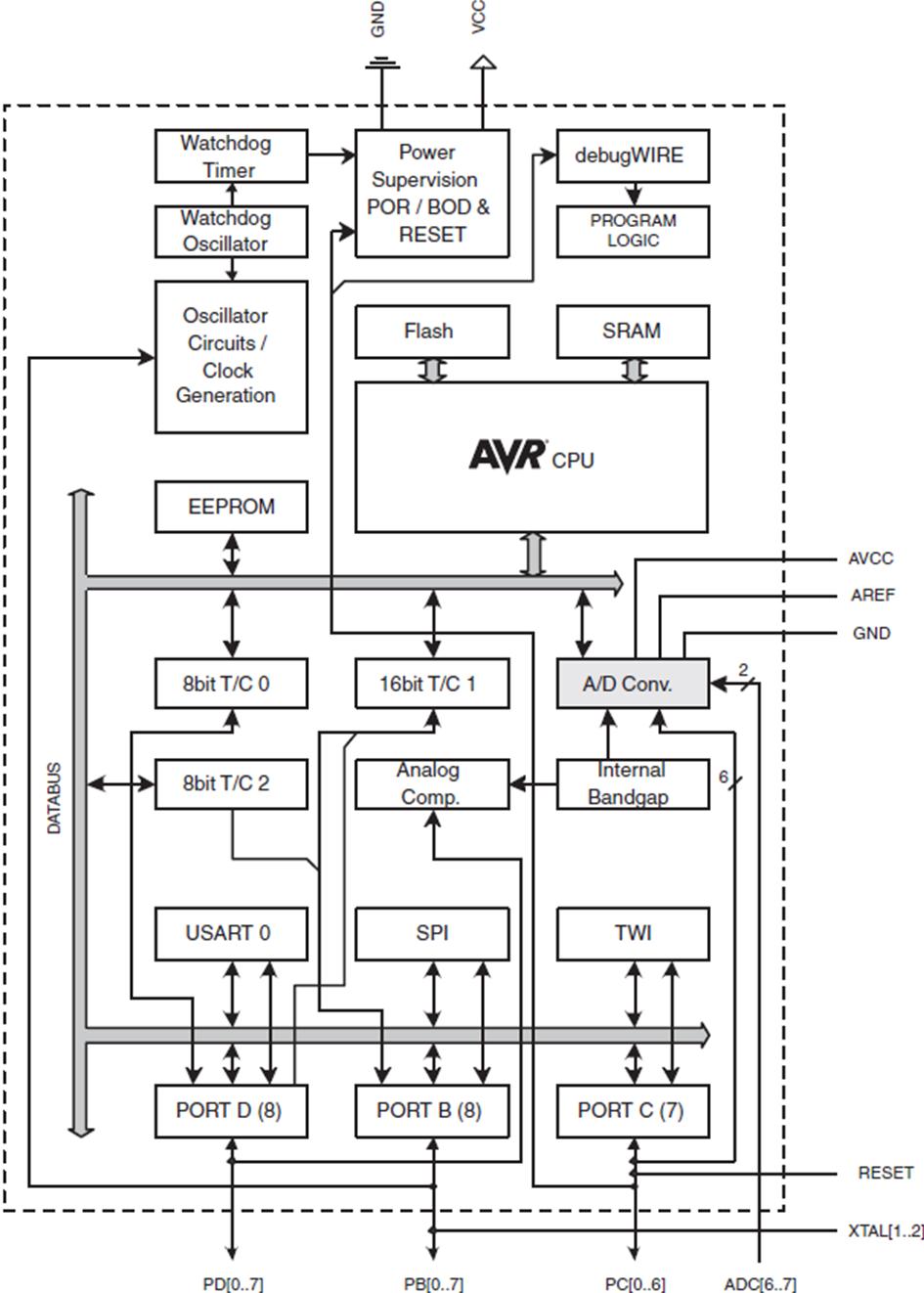
Figure 9 shows the "inner workings" of the ATmega328P microcontroller used on the Elektor Arduino Nano Training Board MCCAB with all its components. The instruction memory (ROM) is called Flash in Figure 9 because of its technology and the RAM is called SRAM to make clear that it is a static RAM that does not need a refresh cycle, as it is required e.g., for the RAM of the PC (see the following section 2.5).
Microcontrollers Hands-On Course for Arduino Starters 20
Timers
Instruction memory ROM (Flash)
Working memory RAM (SRAM)
Central Processing Unit (CPU)
Analog / DigitalConverter
Input / Output (Ports)
2.4 From Microprocessor to Microcontroller 21
Figure 9: Block diagram of the microcontroller ATmega328P (Microchip Technology Inc.)
TWI (= I2C)
USART SPI Serial
Interfaces
2.5 The Differences between Microcontroller and PC
To make the connections a little clearer for the beginner, we will now take a closer look at the individual components in Figure 8 in the case of the microcontroller and in comparison with the PC (personal computer), which we are all familiar with, and show the not inconsiderable differences between the two systems.
In principle, the PC and the microcontroller are very similar, because both require the components shown in Figure 8. On the other hand, they are worlds apart, because both are aimed at completely different market segments. Figure 10 shows the essential similarities, but also the differences between the two systems.
Component PC Microcontroller
1. Processor, CPU CISC architecture 1) Clock frequency: some giga hertz
2. Instruction memory Hard disk / SSD 3) Capacity: some tera bytes
3. Working memory (dynamic) RAM capacity: some giga bytes
RISC-architecture 2) Clock frequency: several mega hertz
FLASH-Memory Capacity: several mega bytes
(static) RAM capacity: a few kilo bytes
4. Operation and display mouse, keyboard and screen Switch, push-button, potentiometer, LEDs, LC-Display
5. Energy demand large (up to several 100 W) small (few mW)
6. Price 300,00 … 2.000,00 € 0,50 … 20,00 €
7. Target application Mass data processing (text processing, image processing, games ...)
Control / monitoring of a specific device ("embedded system") 4)
1) Complex Instruction Set Computer (Computer with complex instruction set, details e.g., under Bibliography [10]
2) Reduced Instruction Set Computer (Computer with reduced instruction set, details e.g., under Bibliography [11]
3) Solid-State-Drive ("Semiconductor drive", for more details, see e.g., Bibliography [12]
4) for more details, see e.g., Bibliography [13]
Microcontrollers Hands-On Course for Arduino Starters 22
Figure 10: The main differences between PC and Microcontroller
A PC is ideally suited for processing mass data, such as that generated in image and text processing. Its need for working memory and hard disk capacity is correspondingly large.
To achieve the often high data throughput, a high clock frequency of the processor (several giga hertz) is required. These features must be paid for with a corresponding price: A processor for a PC costs several 100 Euros.
The ROM of the PC splits into two components. On the one hand, there is the bootstrap memory on the motherboard, an integrated circuit from which the CPU reads out its first commands for loading the operating system after the operating voltage is switched on. This and the application programs are located on a hard disk or SSD 3) on page 22 . The hard disk is not a "real" ROM, since the CPU also stores data on its hard disk in addition to the executable programs, i.e., it can also write to the hard disk while the program is running. However, like the classic ROM, it has the function of a permanent mass memory that does not lose its contents after the operating voltage is switched off. Storage takes place either on an electromechanical drive with a magnetic hard disk or on a much faster SSD (solid state drive), in which the data is stored in integrated, non-volatile semiconductor memories.
The RAM of the PC is a dynamic semiconductor memory module that is plugged onto the motherboard and into which the CPU loads the program from the hard disk via the system bus for execution. The PC therefore not only stores intermediate results in its RAM, but the actual program sequence also takes place in the PC's working memory, the RAM. A dynamic RAM must be refreshed periodically at intervals of a few milliseconds (refresh cycle), i.e., the stored data must be read out and written back again, otherwise they are lost.
The input / output units for communication with the environment are, in the case of the PC, mainly connections for screen, keyboard, mouse, printer ...
The additional function blocks of the PC can be, among other things, a USB, Ethernet, WLAN interface, sound card, etc.
The individual components are connected via a bus system on the system circuit board (the motherboard) through which the data exchange takes place.
In contrast, a few megabytes (often even a few kilobytes) of instruction memory are usually sufficient for the microcontroller to control "its" de-
2.5 The Differences between Microcontroller and PC 23
vice. Its working memory and clock frequency are also far smaller than those of a PC. On the other hand, price is a decisive criterion, because microcontrollers are often used in mass-produced articles where every cent counts in the manufacturing costs. Depending on the number of units ordered, a microcontroller is available at prices ranging from less than one euro to about 20 Euros.
The ROM and RAM of the microcontroller are pure semiconductor circuits located directly on its chip. The RAM is designed in static technology (SRAM) and therefore no refresh cycle is required.
Its input/output units are digital transistor switching stages – so-called ports – whose data direction can be switched between input and output by software.
Its additional function blocks are, for example, serial interfaces (USB, UART, SPI, I2C ... ), analog/digital and digital/analog converters, timer and counter circuits ...
Data exchange takes place via a chip-internal bus system that connects all components with each other.
As you can see, a direct comparison of the two systems is not possible because the objectives are very far apart (Item 7 in Figure 10). The fact remains, however, that both have the essential components of a computer, such as CPU, instruction and working memory, as well as facilities for inputting and outputting data.
2.6 The Procedure for using a Microcontroller
In principle, using a microcontroller is quite simple: The user writes a program on his PC in the Arduino IDE (integrated development environment, see chapter 3.6) that defines the actions to be performed.
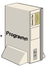
Figure 11 shows the procedure for creating the program: The source code is created with the IDE's editor. A compiler, also integrated into the IDE, translates these program instructions into machine code that the microcontroller can “understand”, consisting of combinations of binary zeros and ones (see section 2.1.1). After compilation, the code is loaded into the microcontroller's instruction memory via the PC's USB interface. The microcontroller runs the program from top to bottom. In microcontrollers, the program usually runs in a so-called infinite loop, i.e., it is executed again and again until the operating voltage is switched off.
Microcontrollers Hands-On Course for Arduino Starters 24
Figure 11: Procedure for creating a microcontroller program
The CPU's sequence control fetches the instructions to be executed from the instruction memory (ROM) one after the other, analyses them and initiates the operation to be executed. If, for example, the (fictitious) binary bit combination 1001 0010 0011 1110 is read, the sequence control "knows" that the content of register A is to be added to the content of register B, at 1100 1101 1110 1111 a value is to be loaded from the working memory into a register, and so on. Registers are special memory cells within the CPU with special properties. From chapter 1, we know that registers control the hardware on the chip of the microcontroller. If a logical or arithmetic operation is to be performed, the operands stored in registers are passed to the ALU (Arithmetic and Logic Unit, see section 3.2). The operands are stored in the RAM in the form of variables (see section 3.4). The processor obtains the information required to carry out its tasks from the outside world with the help of its input/output unit, and uses it to output the results to the connected components or devices.
After an instruction has been processed, the sequence is continued by fetching the next instruction ...
Due to logical decisions in the program sequence or due to interrupts (program interruptions initiated by an external device or one of the components for additional functions on the microcontroller chip, see section 3.11.4), the sequential sequence of program processing can also be interrupted by a jump to another part of the program and continued from another point.
2.7 Data Traffic with the "Outside World"

To perform its tasks, a microcontroller necessarily needs to read data from the "outside world" – e.g., from a switch, a sensor or a variable resistor
2.7 Data Traffic with the "Outside World" 25
Editor: ... // setup function: setup() { // initialize serial: Serial.begin(9600); } ... Source Code Compiler: ... 1001 0010 0011 1110 1100 1101 1110 1111 1000 0001 1101 0010 1010 0101 1100 0110 0000 0001 1101 0111 ... Machine Code
Program
USB Transfer Microcontroller board
(potentiometer) – and output data to the outside world – e.g., to a lightemitting diode, a display or a motor.
When entering and outputting data, a distinction must be made between analog and digital data. The microcontroller can only process digital data directly. To process analog data (e.g., an analog voltage, a temperature or brightness value or the speed of a motor), converters are required that convert the analog value into a digital numerical value.
2.7.1 Digital Inputs/Outputs (GPIOs)
A digital input/output pin of a microcontroller is called GPIO (General Purpose Input/Output) to express its general usability for digital input/output, because the user can configure a GPIO as an input or as an output depending on the requirements in its program.
There are only two states for GPIOs:
1. either voltage is present (this state is called logic 1 or HIGH).
2. or no voltage is present (state logical 0 or LOW).
All values smaller than half the operating voltage are considered logical 0 or LOW and all values that are larger than half the operating voltage are considered logical 1 or HIGH. Intermediate values are quantized to 0 or 1!
Digital input
So when we read the state of a digital input later in our exercises, we get – as shown in Figure 12 –either a HIGH level (logic 1) or a LOW level (logic 0), depending on whether the voltage at the input in question is greater or less than half the operating voltage.
The state at an unconnected digital input is undefined! With a MOSFET switching transistor
(symbolized by switch S1 in Figure 12) inside the microcontroller, the resistor RPU can therefore be connected to the input pin.
Microcontrollers Hands-On Course for Arduino Starters 26
+5 V 0 V +2,5 V LOW HIGH i nternal system bus +5 V RPU S1
Pin
Figure 12: Digital microcontroller input
Microcontroller
When the switch S1 is closed, this so-called pull-up resistor RPU pulls the line to HIGH potential when the input is open and thus ensures a defined input state.
Digital output
The structure of a digital output stage is symbolized in Figure 13 by the two switches S2 and S3. Of course, in the real microcontroller, S2 and S3 are not mechanical switches, but MOSFET switching transistors capable of switching currents of up to 40 mA.
To apply a LOW level to the output pin, switch S2 must be open and switch S3 must be closed, as shown in Figure 13. In this constellation, the ground potential 0 V is connected to the output pin. To set the output to logic 1 (HIGH level), switch S2 must be closed and switch S3 must be open to switch the operating voltage +5 V to the output pin.
An internal logic ensures that both switches cannot be closed at the same time, because this would cause a short circuit between the operating voltage +5 V and the ground potential 0 V of the circuit.
GPIO pin configuration
Each GPIO pin of the microcontroller is wired with an input and an output stage, as shown in Figure 14.
With the function pinMode()
(see section 3.12.3) the GPIO can be configured either as input or as output.
If the GPIO is set up as an input, internal logic ensures that both MOSFET switches S2 and S3 are open as shown in Figure 14.
2.7 Data Traffic with the "Outside World" 27
Figure 13: Digital output
S2 0 V i nternal system bus +5 V RPU S1 S3 +5 V GPIO-Pin i nternal system bus Microcontroller +5 V S2 S3 internal system bus 0 V Pin
Figure 14: GPIO configuration
This isolates the entire output stage from the GPIO pin. If the GPIO is configured as an output, the current output level can also be read via the input stage.
iThe data direction "input" or "output" of a GPIO is configured with the function pinMode() from section 3.12.3.
To generate a LOW or HIGH level at a digital output, there is the function digitalWrite() described in section 3.12.5.
To read the state at a digital input, the function digitalRead() described in section 3.12.6 is used.
2.7.2 Analog Inputs/Outputs
From section 2.1, we know that a microcontroller can process only digital data – i.e., numerical values. To communicate with the analog outside world, it needs converters that convert analog values into the digital values it can process, and converters that can convert its internal binary values into analog values (see Figure 7).
2.7.2.1 The Analog to Digital Conversion
Figure 9 shows that the ATmega328P microcontroller on the Elektor Arduino Nano Training Board MCCAB that we use for our exercises in this course has an analog to digital converter (ADC) on its chip for converting analog voltages into binary numerical values that it can process. Figure 15 shows the internal structure of this ADC.
The ADC of the ATmega328P quantizes the analog input signal in 210 = 1024 steps (see Figure 3 and Figure 4 in section 2.1). The result of an analog to digital conversion is a 10-bit binary number (for "binary numbers" see section 2.1.1).
Via the analog multiplexer AMUX (a multiplexer is the electronic equivalent of an electromechanical selector switch as sketched in Figure 15), one of eight analog voltages VA0 ... VA7 can be applied to the input of the ADC. The software selects the desired input. The ADC of the ATmega328P converts this analog voltage value VADC into a natural number value Z (natural numbers are integers greater than or equal to zero).
The ADC creates the number Z from the analog input voltage UADC according to Equation 1 below:
Microcontrollers Hands-On Course for Arduino Starters 28
Analog connections of the microcontroller (partly led out on pin header SV6 of the Elektor Arduino Nano Training Board MCCAB)
In Equation 1, VADC is the input voltage and VREF is the reference voltage of the analog/digital converter. N is the number of binary digits of the ADC result, in the case of the ATmega328P N = 10.
The switches REFS1 and REFS0 can be used to select either the operating voltage AVcc = +5 V of the ADC, a chip-internal +1.1 V voltage (called "Internal Bandgap" in Figure 9) or the voltage VREF at input REF of the pin connector SV6 on the Elektor Arduino Nano Training Board MCCAB as the reference voltage for the ADC.
The numerical range of Z depends on the resolution of the ADC, i.e., on the number of its quantization levels. In general, an N-bit ADC converts a voltage between 0 V and VREF into 2N numerical values linearly. The lowest number has the value 0 and the highest number has the value 2N – 1. For the 10-bit ADC of our ATmega328P, this results in the range
Z = 0 ... (210 – 1) = 0 ... 1023.
2.7 Data Traffic with the "Outside World" 29 Z = N REF ADC V V 2 = 1024 REF ADC V V , where 0 VADC < VREF (Equation 1)
Figure 15: The analog/digital converter (ADC) of the microcontroller ATmega328P
AVcc = +5 V 1,1 V AMUX A1 A2 A3 A4 A5 A6 REF A7 A0 VREF REFS1 VADC REFS0 ADC Z D A ATmega328P
In the basic setting (default) after switching on the operating voltage of the Elektor Arduino Nano Training Board MCCAB, the switches REFS1 and REFS0 are in the position shown in Figure 15, i.e., the +5 V operating voltage AVcc of the ADC is also its reference voltage VREF. In this case, the input REF on the pin header SV6 must remain unconnected, otherwise the two switches REFS1 and REFS0 act as a short-circuit between the voltage at the pin REF and the voltage AVcc!
At the reference voltage VREF = +5 V, the ADC of the ATmega328P with its 210 = 1024 quantization stages achieves a resolution of
VLSB is the smallest resolution an ADC can achieve, i.e., the voltage value that results in the number Z = 1 with its A/D conversion. The LSB (Least Significant Bit) is the least significant bit position (the rightmost digit) of a binary number.
The permissible voltage range at an analog input of the microcontroller is therefore
VADC = 0 +4,995 V at +5 V reference voltage.
Failure to observe the following warnings may result in permanent damage to the ADC or the entire microcontroller!

1. The input voltage VADC of the analog to digital converter must always be lower than the value VREF of the reference voltage!
2. The reference voltage VREF of the ADC must be in the range +1.0 V VREF +AVcc, it must never be higher than the supply voltage AVcc of the analog to digital converter! On the Elektor Arduino Nano Training Board MCCAB, the analog supply voltage AVcc is identical to the digital supply voltage Vcc = +5 V.
3. If an external voltage is connected to the REF pin of socket SV6, the internal reference voltages must not be used (i.e., switch REFS0 in Figure 15 must be open), otherwise there will be a short circuit between the internal voltage selected with switch REFS1 and the external voltage. The user must set the desired reference voltage before connecting the external reference voltage to the REF pin of pin connector SV6.
Microcontrollers Hands-On Course for Arduino Starters 30
mV V V V N REF LSB 5 1024 5 2
In the Arduino IDE there is the function analogRead() – see section 3.12.6 – to read an analog voltage value and the function analogReference() – see section 3.12.7 – to select the reference voltage.
2.7.2.2 The Digital to Analog conversion
Often a microcontroller needs to output the results of its task in an analog form, for example to control the brightness of lights or the speed of motors. However, while almost all microcontrollers have an A/D converter (ADC) on chip, "real" D/A converters (DAC), which supply a DC voltage as an output value, are rather rare and are found only in higher-priced microcontrollers. However, practically all microcontrollers have internal timers (one of the "additional functions" in Figure 8), which in their "PWM mode" (PWM = Pulse Width Modulation) enable the output of analog values in an indirect way.
A PWM signal is a square wave signal vS in which the duty cycle is varied. The duty cycle D is the ratio of the duration of the HIGH component tH (i.e., the pulse width) of a signal to the total period duration T of the signal (see Figure 16):
The arithmetic mean value VM of the PWM signal is:
(Equation 2)
where V ˆ is the peak value of the square wave signal vS (Figure 16). Since V ˆ and T are constant quantities, a change in the pulse width tH causes a proportional change in the mean value VM.
An RC low-pass connected to the timer output for averaging filters out the DC voltage component VM from the square-wave signal vS (further information on this can be found in [18] of the bibliography). If the cut-off frequency fc of the low-pass filter is chosen very low compared to the frequency f = 1/T of the PWM signal, the higher frequency components contained in the square-wave signal are (almost) completely suppressed and only the DC component of the PWM signal is obtained at the output of the low-pass filter.
2.7 Data Traffic with the "Outside World" 31
T t D H
V T t V D V H M ˆ ˆ
i
The following Figure 16 shows three PWM signals with different duty cycles D and the resulting mean value VM of the DC voltage component in dashed lines.
Figure 16: DC voltage components of various PWM signals
Depending on the application, the effect of averaging can also be achieved without a low-pass filter connected to the timer output. The prerequisite is that the connected load has sufficient inertia.
If, for example, we dim a light bulb or a light-emitting diode (LED) directly with the PWM signal, the LED is switched on and off at the frequency of the PWM square-wave signal (a few 100 Hz), i.e., it lights up "at full power" for the time of the HIGH component and not at all for the time of the LOW component. The "dimmer effect" is caused by the inertia of the human eye, which makes it act like a low-pass filter. A "fast eye" would indeed see an LED flickering with the frequency of the PWM signal. However, due to its inertia, the eye only perceives the average value of the incoming light signal, so we see a continuously lit LED whose brightness is determined by the duty cycle.
Another example is the control of the rotational speed of a DC motor. It also behaves like a low-pass filter due to its mechanical inertia, so we can control its speed by varying the duty cycle D of the PWM signal. However, if a real DC voltage is required for a project, we have to realize the necessary low-pass filter as an electronic circuit, in the simplest case with the help of a resistor and a capacitor as an RC low-pass circuit, more details on this can be found, for example, in [18] of the bibliography.
iIn the Arduino IDE, there is the function analogWrite() – see section 3.12.8 – for outputting a digital 8-bit number as a PWM signal with the corresponding duty cycle.
The function analogWrite() converts natural number values (natural numbers are integers greater than or equal to zero) into PWM signals with the corresponding duty cycle and outputs these PWM square-wave signals on the Elektor Arduino Nano Training Board MCCAB at the pin connector SV5
Microcontrollers Hands-On Course for Arduino Starters 32
VM VM VM T tH vS vS vS t t t V ˆ V ˆ V ˆ 0 0 0
(see section 2.8). Not all GPIOs of the microcontroller can be used for PWM, only the pins ~IO3, ~IO5, ~IO6, ~IO9, ~IO10 and ~IO11 are available. The character "~" in front of the pin’s name indicates that it is a PWM-capable output of the microcontroller. The PWM signal has the frequency fPWM = 976 Hz at the connections ~D5 and ~D6 and the frequency fPWM = 490 Hz at all other PWM connections.
In general, with N bits 2N different numerical values Z = 0 ... (2N – 1) can be represented. For the duty cycle D of the PWM signal this means:
The function analogWrite() receives 8 bit binary numbers, i.e., N = 8, Z = 0 ... 255. This results in the duty cycle D of the PWM signal:
For the mean value VM of the PWM signal we get
2.7.3 Serial Inputs/Outputs
The AVRs, including the ATmega328P on the Arduino® NANO board, are 8bit microcontrollers, i.e., eight bits (= 1 byte, see section 2.1.1) are always processed simultaneously (see also section 3.2). To output one byte to the outside world, eight parallel lines and eight digital output ports would be required. This has actually been done in the past (keywords: "parallel port", "printer interface"). However, since the number of available input/output pins on a microcontroller is limited (on the Arduino® NANO, a maximum of 20 I/O ports are available) they should be used sparingly. In order not to "waste" eight "valuable" input/output pins (GPIOs) of the microcontroller, bits that have been combined into a byte are in most cases not output in parallel via eight GPIOs at the same time, but serially, i.e., bit by bit one after the other via only one pin. Figure 18, Figure 20 and Figure 21 show examples. The receiver reassembles the eight bits arriving one after the other into the original byte.
In serial data transmission, the bits are transmitted with a defined clock frequency that determines the transmission time of the individual bits. The frequency fT of the clock signal determines the speed at which the bits are
2.7 Data
"Outside
33
Traffic with the
World"
N H Z T t D 2
256 28 Z Z D (Equation
3)
V Z V D VM ˆ 256 ˆ (Equation
4)
transmitted. If, for example, the clock frequency fT = 1000 Hz, a clock pulse has the period duration TT = 1 / fT = 1 / 1000 Hz = 1 ms. This means that the transmission of a bit in this example takes 1 ms and that 1000 bits can be transmitted within one second.
The number of bits transmitted in one second at the set clock frequency is called the bit rate (bits per second, bits/s or bps). When transmitting binary signals (i.e., only logical 0 or logical 1), the unit baud (symbols per second or Bd) is also permissible, which we will use in the following when dealing with the settings of the serial interface.
Regarding serial interfaces, a distinction is made between synchronous and asynchronous transmission. With a synchronous interface, the transmitter also sends the clock signal to the receiver via a separate output. With the asynchronous interface, the receiver must determine the start of the individual bits itself by measuring the time that has elapsed since the start bit. To do this, the transmission time of the bits, which is determined by the baud rate, must be adhered to exactly. This is ensured with today's microcontrollers, as their clock system operates with quartz precision.
2.7.3.1 Synchronous Data Transmission via the I2C, SPI and USART Interface
For data exchange with external integrated circuits, sensors or modules, the I2C or SPI interface is often used in electronics. On the Elektor Arduino Nano Training Board MCCAB (chapter 2.8), for example, the LC-Display is controlled via the I2C interface. On the AVR microcontrollers, which include the ATmega328P, the I2C interface is called the TWI interface (Two Wire Interface). The TWI interface is functionally identical to the I2C interface.
As Figure 9 shows, the ATmega328P microcontroller has both a hardware SPI (Serial Peripheral Interface) and a hardware I2C (Inter-Integrated Circuit) interface on its chip, both "additional functions" in Figure 8 for synchronous serial transmission and reception of data.
The USART / UART of the AVR in Figure 9 can be used universally: on the one hand as USART for synchronous serial transmission and on the other hand as UART for asynchronous serial transmission following the RS-232 standard.
For interfaces with synchronous transmission (USART, SPI, TWI = I2C), a clock signal synchronizes the receiver with the transmitter and indicates
Microcontrollers Hands-On Course for Arduino Starters 34
when the transmitter has shifted a new bit to its data output and when the receiver can accept it at its data input.
The clock signal is generated by the transmitter and is connected to the clock input of the receiver. The serial data output of the transmitter is connected to the serial data input of the receiver.
The following Figure 18 shows the principle of synchronous serial transmission of a data word consisting of eight bits B0 … B7.
During synchronous serial transmission of a byte according to Figure 18, the transmitter shifts the eight bits one after the other to its serial data output, which is connected to the serial data input of the opposite side. With the rising edge of the clock signal, it indicates to the receiver that a bit is being shifted to the data output, and with the falling edge, it signals to the receiver that the bit is now stable on the data line and can be taken over. With each falling edge of the clock signal, the receiver accepts a bit present at its serial data input and shifts it into the "receive byte". After eight clock pulses, a complete byte was transmitted to the receiver.
2.7 Data Traffic with the "Outside World" 35
Figure 17: Connection of the transmitter to the receiver in a synchronous serial transmission
Figure 18: Principle of synchronous serial transmission of eight data bits
B0 B1 B2 B3 B4 B5 B6 B7 1 2
t clock data bits t TT Transmitter (e.g.
Data Clock Data Clock Receiver
: shift out the next bit : take over bit
Arduino board)
(e.g. LC display)
2.7.3.2 Asynchronous Data Transmission via the UART of the Microcontroller
The ATmega328P microcontroller on the Elektor Arduino Nano Training Board MCCAB (chapter 2.8) has a hardware UART (Universal Asynchronous Receiver / Transmitter, one of the "additional functions" in Figure 8) on its chip for the serial transmission and reception of data. In the block diagram in Figure 9 we see the designation USART (Universal Synchronous and Asynchronous Receiver / Transmitter), as this serial interface can also be operated synchronously. To output a byte via the UART, the CPU only has to write the byte to be transmitted into the UART's transmit register, the UART takes care of everything else. A byte received serially from an external transmitter is written by the UART independently into a receive register, from which the CPU can read it out. are managed by the Arduino IDE in the background - unnoticed by the user
In the Arduino IDE (chapter 3.6), the asynchronous serial transmission and reading of data is done via buffers. Both the receive and the send buffers are 64-byte areas in the working memory (RAM) that are managed by the Arduino IDE in the background - unnoticed by the user. As soon as a byte arrives via the UART, it is automatically transferred from the receive register of the UART to the receive buffer, from which the user program can read it using the Serial.read() method explained in section 3.12.14.4. When the user program wants to send a byte, it writes it to the send buffer using the Serial.print() method explained in section 3.12.14.2, and as soon as the UART is ready for transmission, the next byte is automatically fetched from the buffer and written to the UART's send register.
Microcontrollers Hands-On Course for Arduino Starters 36
Figure 19: Communication of two devices via the asynchronous serial interface
Device 1 Device 2 Tx Rx UART Rx Tx UART
Figure 19 shows how two devices are connected for communication via the asynchronous serial interface. The UART sends the individual bits to the
receiver via its output Tx (transmitter) and receives the bits sent by the opposite transmitter via its input Rx (receiver). The transmit output Tx of one device must therefore be connected to the receive input Rx of the other device.
Figure 20 shows the principle of asynchronous serial transmission of a byte consisting of eight bits via the UART. In the idle state, the Tx and Rx lines are at +5 V level. The sender announces the start of a transmission with the start bit, which sets the Tx line to the potential 0 V. The start bit is followed by the individual data bits, starting with the least significant bit B0 of the byte. In most cases, exactly the eight bits of a byte are transmitted, but with most UARTs – including that of the ATmega328P – a different number of data bits can be set.
Figure 20: Serial asynchronous transmission of a byte via the UART
After the last data bit, a parity bit can follow for a simple check of the correctness of the transmission. The check can be set to even or odd parity. When checking for even parity, the parity bit is selected so that the sum of all data bits and the parity bit is an even number. When checking for odd parity, the parity bit is selected so that the sum of all data bits and the parity bit results in an odd number. If, for example, the sum of all data bits and the parity bit of a received byte results in an odd number, although even parity was set, the user program can recognize from this that an error must have occurred during transmission.
After the parity bit or – in the case the parity check is waived – after the last data bit, one or two stop bits with +5 V level follow on the data line. If another data transmission is pending, the stop bit can be immediately followed by a new start bit, otherwise the line goes into the idle state, i.e., it remains at the +5 V level of the stop bit.
The user manual of the Elektor Arduino Nano Training Board MCCAB (see bibliography [6]) shows that the serial ports TxD and RxD of the
2.7 Data Traffic with the "Outside World" 37
t Tx / Rx idle state start bit data bits (logical 0 or 1) parity bit stop bit(s) 0 1 2 3 5 6 4 7 +5 V 0 V
ATmega328P on the Arduino NANO are connected via two protective resistors to the integrated converter circuit, which adapts the USB interface of the PC used as the development station to the UART interface of the ATmega328P.
The default settings in the Arduino IDE for asynchronous serial transmission are 8 data bits, no parity check and 1 final stop bit. Using the Serial.begin() method explained in section 3.12.14.1, these settings can be changed if necessary.
Example:
Transmission of the data byte 0110 01012 = 6516 via the serial interface of the microcontroller ATmega328P in the configuration of the Arduino IDE, i.e., without parity bit.
2.8 The Elektor Arduino Nano Training Board MCCAB
In principle, we could also assemble the circuits needed for our practical exercises in chapter 4 of the book with discrete components, which we plug onto a breadboard together with a lot of connecting cables. However, this plugging often takes more time than writing the actual program and the circuit for e.g., a running light with 11 light-emitting diodes and the corresponding series resistors on a breadboard is anything but clear. In addition, such a hardware structure is a source of errors that should not be neglected! For these reasons, the Elektor Arduino Nano Training Board MCCAB was developed. On this board, an extensive range of accessory
Microcontrollers Hands-On Course for Arduino
38
Starters
Figure 21: Serial asynchronous transmission of the byte 0110 01012 via the UART
t Tx / Rx idle state start bit Stop bit +5 V 0 V data bits 0 … 7 0 1 2 6 3 5 4 7
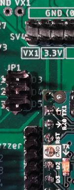
components (switches, buttons, LEDs, potentiometers, buzzers, LCDisplay, interfaces and level converters for serial connections, driver stages for external devices) are already connected to the plugged-in microcontroller module or can be connected to it by simple jumpers. Entire external modules can also be plugged into the Elektor Arduino Nano Training Board MCCAB via a socket connector or connected to it via the serial interfaces on the training board. They can be controlled by the microcontroller on the training board. This eliminates the tedious assembly of the training circuits and we can concentrate on the essentials – i.e., our software, the "program".
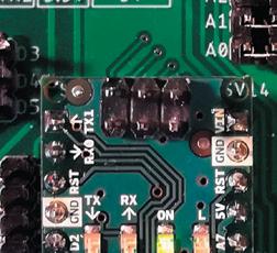
We will therefore load the programs created in our exercises into the ATmega328P microcontroller on the Elektor Arduino Nano Training Board MCCAB, where they will be runned. Figure 1 on page 12 shows the ATmega328P microcontroller chip. Some of the 32 pins of the microcontroller visible in Figure 1 are used for its power supply, for connecting a crystal to its built-in oscillator for clock generation or as a RESET input for the pushbutton switch on the microcontroller module (arrow (1a) in Figure 22), whose actuation resets the microcontroller to a defined initial state and restarts the program.
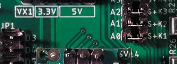
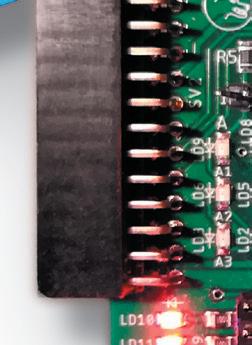
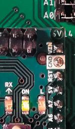
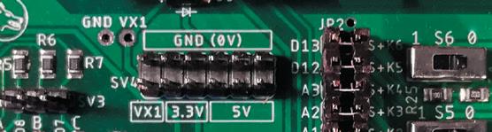
However, the vast majority of the connections are available as general purpose inputs/outputs (GPIOs, see section 2.7.1), which the microcontroller can use to connect to the outside world. On the Elektor Arduino Nano Training Board MCCAB, these pins – with a few exceptions reserved for internal purposes – are led out to the connector strips SV5 and SV6 ( in Figure 22). The connections D2 to D13 are digital inputs / outputs (GPIOs), the connections A0 to A3 can also optionally be connected to the internal ADC (Analog / Digital Converter) of the ATmega328P and thus be used as analog inputs.
The Elektor Arduino Nano Training Board MCCAB is equipped with many hardware components (switches, buttons, LEDs, potentiometers, buzzers, LC-Display ... ), which enable the performance of numerous projects and exercises that are very suitable for beginners.
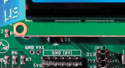
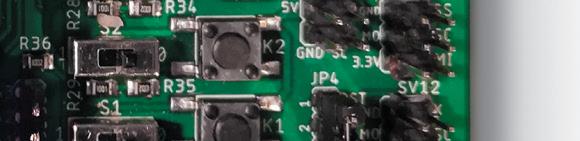
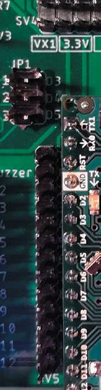
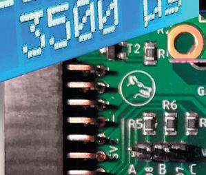
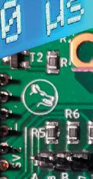
Figure 22 shows a view of the Elektor Arduino Nano Training Board MCCAB with its color-coded function blocks. The operating instructions for the Elektor Arduino Nano Training Board MCCAB with a detailed description of all components can be downloaded free of charge to your own PC via the link mentioned in section 8.2.
2.8 The Elektor Arduino Nano Training Board MCCAB 39
(2) Pin headers SV5 and SV6 for the microcontroller inputs/outputs. The GPIOs (General Purpose Inputs / Outputs) of the microcontroller can be connected to internal components of the training board or external modules via these two pin headers using Dupont cables.
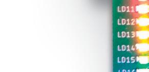
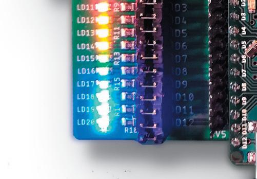
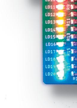
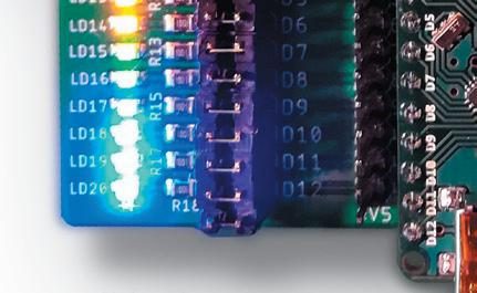
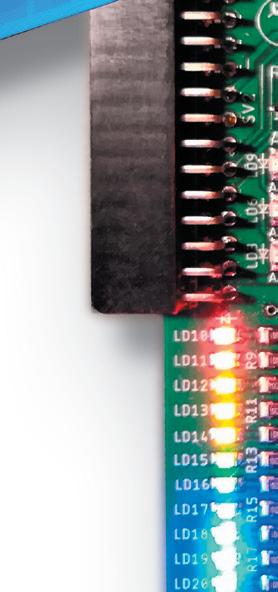
(3) 11 LEDs LD10 ... LD20 (status indicators for the inputs / outputs D2 ... D12 of the microcontroller), each LED can be connected to the assigned GPIO D2 ... D12 via a jumper on header JP6.

Microcontrollers
40
Hands-On Course for Arduino Starters
Figure 22: Block diagram of the Elektor Arduino Nano Training Board MCCAB
The Function Blocks on the Elektor Arduino Nano Training Board MCCAB
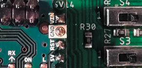
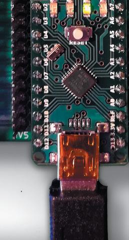
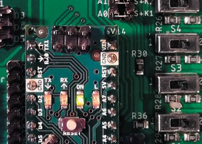
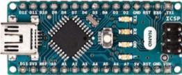
(1) Microcontroller module Arduino® NANO with RESET button (arrow 1a), light-emitting diode "L" (arrow 1b) and mini-USB socket for connection to the user's PC.
8 1 1 4 3 6 5 1 2 6 9 7 1 0 2 2 1a 9 1b 1
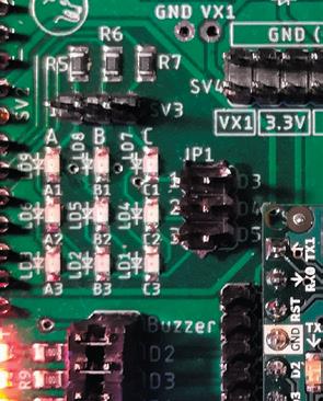
(4) 3 3 LED matrix LD1 ... LD9 (9 red LEDs). The column lines are permanently connected to the outputs D6 ... D8 of the microcontroller, the row lines can be connected to the GPIOs D3 ... D5 by jumpers on the socket strip JP1.
Caution:
If the row lines of the 3 3 LED matrix are either connected to the GPIOs D3 ... D5 via jumpers on the pin header JP1 or to other GPIOs of the microcontroller via Dupont cables, these row lines as well as the column lines D6 ... D8 must never be used for other tasks in a sketch. Double assignment of the matrix GPIOs would lead to malfunctions or even damage to the Elektor Arduino Nano Training Board MCCAB!
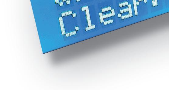
(5) LC-Display with 2 x 16 characters, connected via the I2C bus to pins A4 and A5 of the microcontroller. By pulling the jumper JP5, the operating voltage of the LCD can be switched off in exercises where the display is not used.
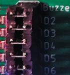
(6) Piezo buzzer Buzzer1, can be connected to the GPIO D9 of the microcontroller via a jumper on the "Buzzer" position of the pin header JP6.
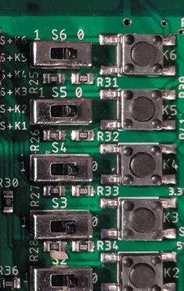
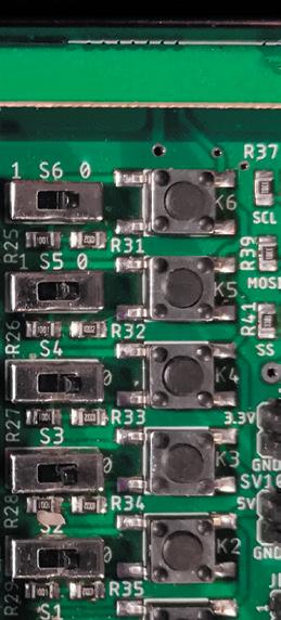
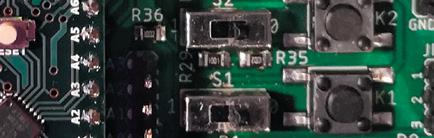
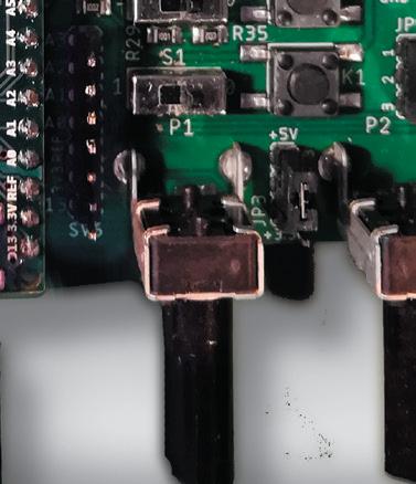
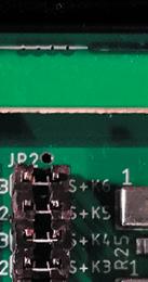
(7) 6 slide switches S1 ... S6, connected in parallel to 6 buttons K1 ... K6. They can be connected to the inputs A0 ... A3, D12 and D13 of the microcontroller via jumpers on the pin header JP2.
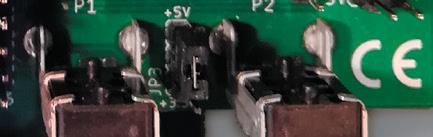
(8) Potentiometers P1 and P2, their wipers are connected to the analog input pins A6 and A7 of the microcontroller. The voltage 3.3 V or 5 V can be applied to the potentiometers via pin header JP3.
Caution:
Pins A6 and A7 of the ATmega328P are fixed as analog inputs due to the internal chip architecture. Configuring them with the function pinMode() (see section 3.12.3) is not permitted and can lead to an incorrect behavior of the program.
(9) Pin headers SV1 and SV7, switching outputs for external devices.
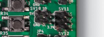
(10) Pin headers for serial connection of external SPI and I2C modules.
(11) Connector strip SV2 with 2 x 13 pins for connecting external modules.
2.8 The Elektor Arduino Nano Training Board MCCAB 41
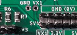
(12) Pin header SV4, distributor for the board's operating voltages.
The voltages can be connected to internal components of the training board or external modules using Dupont cables.
The two somewhat more complex functional units 3 x 3 LED matrix ( in Figure 22) and LC-Display ( in Figure 22) will be explained in more detail here. For all others, please refer to the detailed description in the Elektor Arduino Nano Training Board MCCAB operating instructions mentioned above (download link in section 8.2).
iTo control the 3 x 3 LED matrix, the LEDs LD10 ... LD20, the buttons K1 ... K6 and switches S1 ... S6 as well as the buzzer Buzzer1, the library MCCAB_Lib (see chapter 3.14) is available, which can be downloaded free of charge by the purchasers of the board from the website mentioned in section 8.2 and integrated into the Arduino IDE.
To control the LC-Display, we use the LiquidCrystal_I2C library (see chapter 3.15), which can be downloaded free of charge from the Internet into the Arduino IDE.
The 3 3 LED Matrix
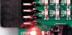
The Elektor Arduino Nano Training Board MCCAB contains nine lightemitting diodes arranged in a matrix ( in Figure 22). Figure 23 shows their basic circuitry.
The matrix consists of three columns and three rows. The columns are labeled A, B and C, the rows are numbered from 1 to 3. At each of the nine intersections of a row with a column, a light-emitting diode is placed whose anode is connected to the column line and whose cathode is connected to the row line. The nine LEDs are labeled according to the columns and rows connected to them, e.g., LED "B2" is connected to column B and row 2.
For an LED to light up, its column line must be at logic 1 (+5 V) and its row line at logic 0 (0 V).
The instruction manual for the Elektor Arduino Nano Training Board MCCAB states, that the column leads are permanently connected to GPIOs D6, D7 and D8 of the microcontroller.
The row leads can be connected to GPIOs D3, D4 and D5 of the microcontroller via jumpers on header JP1.
Microcontrollers Hands-On Course for Arduino Starters 42
If the row lines of the 3 3 LED matrix either are connected to the GPIOs D3 ... D5 via jumpers on the pin header JP1 or to other GPIOs of the microcontroller via Dupont cables, these row lines and the column lines D6 ... D8 must not be used for other tasks in a sketch. Connecting the matrix GPIOs in this way would lead to malfunctions or, in the worst case, even damage to the Elektor Arduino Nano Training Board MCCAB!
If the matrix is not used in a sketch, the jumpers on the header JP1 of the Elektor Arduino Nano Training Board MCCAB should be removed.
Advantage of the matrix arrangement
If we were to control nine LEDs individually, 9 GPIOs of the microcontroller would be required. By arranging the LEDs in a matrix, we only need 6 GPIOs. The more LEDs are controlled, the more the advantage of matrix control becomes apparent: with a matrix consisting of 8 columns and 8 rows, 64 LEDs can be controlled. Compared to individual control, 48 GPIOs can be saved!
We know LED matrices from perimeter advertising in football stadiums, for example, where colored high-power LEDs are used in a matrix arrangement to generate moving images.
Controlling the matrix in multiplex mode
Figure 23 shows that each column line and each row line of the matrix on the Elektor Arduino Nano Training Board MCCAB is connected to three LEDs each. This means that the simultaneous control of all rows and columns would not work, as LEDs that should actually be switched off would also light up unintentionally. Instead – as shown in Figure 24 – only one row line may be active at a time and the column lines must apply the bit pattern for the three LEDs of the currently activated row.
2.8 The Elektor Arduino Nano Training Board MCCAB 43
A 1 B 1 C 1 C 2 B 2 A 2 A 3 B 3 C 3 c olumn A D8 column B D7 column C D6 row 2 D4 row 3 D5 row 1 D3
Figure 23: 3 x 3 LED Matrix
The other two row lines must be open during this time or switched off by an applied HIGH level, so that no current can flow through them. If the three lines are activated cyclically in a sufficiently rapid sequence as in Figure 24, the observer sees a static image of all nine LEDs due to the inertia of the human eye. The user program controls the LED matrix in an endless loop, in which one of the three rows 1, 2 or 3 is cyclically set to LOW potential while the other two rows are set to HIGH level.The column connections of all light-emitting diodes that are to light up in the currently active row are set to HIGH level. The column connections of the LEDs in the active row that are not to be lit are at LOW potential.
Figure 24: Periodic stepwise activation of the three rows of the matrix
For example, to light up the two LEDs A3 and C3, row 3 must be at LOW level and columns A and C at HIGH level, while the two row lines 1 and 2 are at HIGH level and column B is at LOW level.
The LC (Liquid Crystal) Display
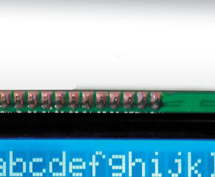
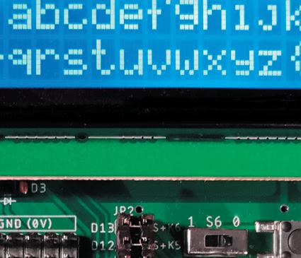
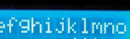
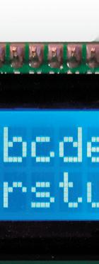
The Elektor Arduino Nano Training Board MCCAB is equipped with an LCDisplay (LCD) that enables the output of texts, numerical values and even self-defined special characters. The display used has 2 lines with 16 columns each, one character can be displayed in each column. Each character is formed from the points of a 5 8 matrix, as shown in Figure 26. The required bit patterns of the 5 8 dot matrix for each individual character are stored inside the LCD controller according to the ASCII table from section 8.1.
Now, the ASCII code (see section 3.3.1) is a 7-bit code (the eighth bit of the ASCII character code has the value 0), but our microcontroller ATmega328P is an "8-bit machine", so it can process a byte in one step and also stores its data in byte format. The developers of the display controller HD44780 (which is standard in this category and can be found on almost all LCD modules) did not want to leave the eighth bit of the byte unused and extended the ASCII character set by another 128 character codes,
Microcontrollers Hands-On Course for Arduino Starters 44
row 1 row 2 row 3 LOW HIGH HIGH row 2 row 1 row 3 LOW HIGH HIGH row 3 row 1 row 2 LOW HIGH HIGH row 1 row 2 row 3 LOW HIGH HIGH step 1 step 2 step 3 step 1 …
where the eighth bit is on logical 1. For this reason, our LCD also uses the character codes 128 to 255 (more or less continuously, see Figure 25).
In addition to the 95 printable characters with the codes 32 ... 126, the ASCII code also has 33 control characters with the ASCII codes 0 ... 31 and 127, which are not printable. The display does not evaluate these control characters for control purposes. The display controller HD44780 is available in two versions: With the ROM code A00 or alternatively with the ROM code A02. The version A00 displays empty dot matrices for the codes 16 ... 31 as well as 128 ... 159. Version A02, on the other hand, also uses these address spaces for character output (see Figure 25). Which of the two ROM versions is installed in the LC-Display of the Elektor Arduino Nano Training Board MCCAB cannot be predicted; the manufacturer of the LCD module makes this selection.
The user can define up to eight special characters and display them on the LCD. The ASCII codes 0 to 7 are assigned to these eight special characters. Optionally, the same eight special characters can also be addressed via the ASCII codes 8 to 15.
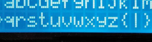
The table in Figure 25 shows the allocation of the character memory of the two variants. In Exercise 42, we show the character set of the LCD on our Elektor Arduino Nano Training Board.
Figure 25: Character memory allocation of the two HD44780 variants
Figure 26 shows the numbering of the rows and columns of the display, which in both cases starts with 0. By specifying these coordinates, a character can be written specifically to a certain position on the display. For
2.8 The Elektor Arduino Nano Training Board MCCAB 45
Character Code ROM Code A00 ROM Code A02 0 … 7 User-defined characters User-defined characters 8 … 15 User-defined characters User-defined characters 16 … 31 (no display) visible characters 32 … 127 visible characters visible characters 128 … 159 (no display) visible characters 160 … 255 visible characters visible characters
this purpose, the LCD has a cursor that determines the position of the character to be written. The LCD library described in Chapter 3.15 contains methods for positioning this cursor (see table in Figure 83).
Although the display can only show 16 characters in each row, the memory in which the characters are stored in the display controller has 40 memory locations for each line. As you can see in Figure 27, there is a gap of 24 memory locations between the last display address 39 of the first line and the start address 64 of the second line.
By means of shift commands, which are contained in the LCD library described in chapter 3.15 (see table in Figure 83), the memory area visible in
Microcontrollers Hands-On Course for Arduino Starters 46
Figure 26: Schematic diagram of the used LC-Display with 16 2 displayable characters
Figure 27: The visible content of the display before and after shifting
16 17 36 37 38 39 00 01 02 03 04 05 06 07 08 09 10 11 12 13 14 15 64 65 66 67 68 69 70 71 72 73 74 75 76 77 78 79 80 81 100 101 102 103 00 17 36 37 38 39 64 01 02 03 04 05 06 07 08 09 10 11 12 13 14 15 16 65 66 67 68 69 70 71 72 73 74 75 76 77 78 79 80 81 100 101 102 103 15 16 17 36 37 38 00 01 02 03 04 05 06 07 08 09 10 11 12 13 14 64 65 66 67 68 69 70 71 72 72 74 75 76 77 78 79 80 81 100 101 102 39 103 Display character memory addresses visible area after right shift visible area after left shift 1 2 3 4 5 6 7 8 9 10 11 12 13 14 15 16 window position 1 2 3 4 5 6 7 8 9 10 11 12 13 14 15 16 window position 1 2 3 4 5 6 7 8 9 10 11 12 13 14 15 16 window position 0 1 2 4 3 15 14 13 12 11 10 5 6 7 9 8 0 1 column number row number
the display can be shifted over the entire memory area like a window (see also Figure 160 and Figure 161).
Figure 27 shows at the top the visible window of the display in the basic setting without previous slide operations, in the middle the display content of the basic setting after a slide operation to the left and at the bottom the display content of the basic setting after a slide operation to the right.
Setting the LCD contrast
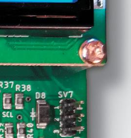
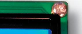
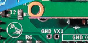
When the Elektor Arduino Nano Training Board MCCAB is delivered, the contrast of the display is not set. For this reason, and because the contrast of the display can change due to environmental conditions (e.g., temperature) or aging, the LCD has a trim potentiometer to adjust the contrast. This trim potentiometer is accessible from the underside of the Training Board and marked with an arrow. This allows the contrast to be adjusted with a small screwdriver during the first start-up or if otherwise required.
Hint:
If no characters are visible on the display after text output when using the LCD for the first time, it is most likely due to the lack of LCD contrast adjustment!
Data transmission from the microcontroller to the LC-Display
On each LCD module there is a display controller HD44780, which receives the (ASCII) codes of the characters sent by the microcontroller via an interface, generates the corresponding characters of the 5 8 dot matrix mentioned above from the codes and displays them on the display surface.
The LCD controller HD44780 has only a parallel interface for receiving the data to be displayed, i.e., the microcontroller writes a data byte consisting of eight bits D0 ... D7 into the input register of the display controller HD44780 on the LCD using three control signals RS, RW and E as shown in Figure 28.
This method of parallel data transfer would considerably limit the resources on the Elektor Arduino Nano Training Board MCCAB, because the LCD alone would already occupy 11 of the 16 freely available pins of the ATmega328P microcontroller!
2.8 The Elektor Arduino Nano Training Board MCCAB 47
Figure 28 Microcontroller RS RW E D0 D1 D2 D3 D4 D5 D6 D7 LCDisplay i
The second possibility of data transmission to the LCD controller HD44780, in which the 8 data bits are transmitted in two packets of 4 bits each one after the other, does not really help either, because even in this case, 7 pins of the microcontroller would still be bound by the LCD, since the three control signals RS, RW, E are also needed in this case.
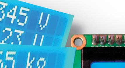
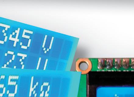
For this reason, the LC-Display on the Elektor Arduino Nano Training Board MCCAB is controlled via the I2C bus (see section 2.7.3.1), a synchronous serial bus that consists of only one data line SDA and one clock line SCL and transmits the data bit by bit using a similar procedure to that shown in Figure 18. The data traffic via the I2C interface is carried out using the two lines A4 (SDA) and A5 (SCL) of the ATmega328P microcontroller (Figure 29).
An additional adapter on the bottom of the LCD module converts the I 2C signals into parallel signals as shown in Figure 28. As Figure 29 shows, the adapter uses the above-mentioned method of transmitting two sets of 4 bits in succession via the data lines D4 … D7, i.e., first the data bits D4 … D7 and then the data bits D0 … D3 are transmitted over the same lines D4 … D7.
Since the two lines A4 and A5 of the microcontroller on the Elektor Arduino Nano Training Board MCCAB are reserved for the I2C interface anyway, no resources are lost with this type of data transmission to the LCD, because in principle several participants can be connected to the I2C bus at the same time. Since each participant connected to the bus has its own I 2C address, it only feels addressed when a data packet with its address arrives.
The LC-Display on the Elektor Arduino Nano Training Board MCCAB usually has the I2C address 0x27. If the address differs due to the manufacturer, this is indicated on the display.
Microcontrollers Hands-On Course for Arduino Starters 48
Figure 29
i RS RW E D0 D1 D2 D3 D4 D5 D6 D7 LCDisplay Adapter Microcontroller A4 A5 SDA SCL
Microcontrollers Hands-on Course for Arduino Starters based on the new Elektor Arduino Nano MCCAB Trainingboard
Thanks to the Arduino approach, even non-professionals can implement their ideas. In light of the current particularly intensive promotion of STEM subjects (mathematics, computer science, natural science, and technology) in schools, Arduino appears a great learning tool. In this microcontroller practical course for starters, you will learn how to develop your own projects with a microcontroller even if you have no prior knowledge with electronics or programming.
The Arduino IDE is a software development environment that can be downloaded for free to your own PC. It o ers the complete software package that you need for your own microcontroller projects. You'll code your programs ("apps") in the C programming language using the editor of the Arduino IDE on your PC. Using the IDE's built-in compiler, you'll translate them into the bits and bytes that the microcontroller understands and load them into the microcontroller's memory via a USB cable.
To create your programs, you don't even need to know the inner life of a microcontroller. The Arduino model provides many free libraries (a kind of "app store") to help you control the function blocks of the microcontroller. These libraries contain readymade "software packages" called functions, which you can integrate into your programs like a "black box".
Elektor Arduino Nano MCCAB Training Board
The MCCAB training board helps you implement your projects. This board is connected to the PC via a USB cable. It contains an Arduino microcontroller module as well as all the components needed for our exercises, such as LEDs, switches, pushbuttons, acoustic signal generators, and more. External sensors, motors or modules can also be polled or controlled with our microcontroller exercise system.
The emphasis of the course is on hands-on exercises. In the first section, you will learn the fundamentals of the hardware and software. The extensive practical part starts with chapter 4 and is quite simple at first. With each additional exercise, new hardware and software components are added and explained. In this way, the beginner gains step by step an increasing level of understanding of the possibilities o ered by a microcontroller.
However, every reader should first study the operating instructions of the MCCAB training board carefully before using it for the first time.
Wolfgang Trampert has been involved in the construction and programming of microcontrollers and their peripherals since his studies in electronics. As the owner of an engineering company, he has developed microcontrollercontrolled products on request. He is active as an author of technical books and articles and conducts training courses on the subject of microcontrollers.
Elektor International Media www.elektor.com