Radio Builder’s Book
From Detector to Software Defined Radio
 Burkhard Kainka, DK7JD
booksbooks

Burkhard Kainka, DK7JD
From Detector to Software Defined Radio
● Burkhard Kainka● This is an Elektor Publication. Elektor is the media brand of Elektor International Media B.V.
PO Box 11, NL-6114-ZG Susteren, The Netherlands
Phone: +31 46 4389444
● All rights reserved. No part of this book may be reproduced in any material form, including photocopying, or storing in any medium by electronic means and whether or not transiently or incidentally to some other use of this publication, without the written permission of the copyright holder except in accordance with the provisions of the Copyright Designs and Patents Act 1988 or under the terms of a licence issued by the Copyright Licencing Agency Ltd., 90 Tottenham Court Road, London, England W1P 9HE. Applications for the copyright holder's permission to reproduce any part of the publication should be addressed to the publishers.
● Declaration
The author, editor, and publisher have used their best efforts in ensuring the correctness of the information contained in this book. They do not assume, and hereby disclaim, any liability to any party for any loss or damage caused by errors or omissions in this book, whether such errors or omissions result from negligence, accident or any other cause. All the programs given in the book are Copyright of the Author and Elektor International Media. These programs may only be used for educational purposes. Written permission from the Author or Elektor must be obtained before any of these programs can be used for commercial purposes.
● British Library Cataloguing in Publication Data
A catalogue record for this book is available from the British Library
● ISBN 978-3-89576-565-0 Print
ISBN 978-3-89576-566-7 eBook
● © Copyright 2023: Elektor International Media B.V.
Translator: Martin Cooke
Editor: Jan Buiting
Prepress Production: D-Vision, Julian van den Berg
Elektor is the world's leading source of essential technical information and electronics products for pro engineers, electronics designers, and the companies seeking to engage them. Each day, our international team develops and delivers high-quality content - via a variety of media channels (including magazines, video, digital media, and social media) in several languages - relating to electronics design and DIY electronics. www.elektormagazine.com
Discover the captivating world of radio technology and unlock the secrets of radio set construction using this comprehensive guide. From the early days of the humble crystal set to the modern wonders of Software-Defined Radios (SDRs), this book takes you on a journey through time and technology. With detailed instructions and step-by-step illustrations, you’ll learn how to build and assemble various receivers to understand their various strengths and weaknesses. Practical antenna design and amateur radio rigs are also covered in this inclusive handbook.
For many years in the early history of electronics, the construction of homebrew radio receivers was the most common entry point to electronics. Nowadays, there are many other routes in, especially through the use of computers, microcontrollers, and digital technology. The analogue roots of electronics are now often overlooked but radio technology is particularly well suited as an introduction to electronics because you will be rewarded with early success from even the most basic circuit. The connection to modern digital technology is also obvious when it comes to modern tuning methods and the use of highly integrated PLL, DDS and DSP radios.
This book aims to provide an overview and present a collection of simple projects to encourage budding engineers along the path of discovery. Now in its second edition, many new projects have been added which include important circuits and cover most recent developments. With this book by your side, you will go on to develop your own ideas and design and test your own receivers.
Wishing you every success and crystal clear reception!
Burkhard Kainka, DK7JD www.elektronik-labor.deBuilding radios is an old hobby that has seen something of a renaissance recently. In addition to the classic and dead simple 'Foxhole’ crystal radio set and more sophisticated vacuum tube receivers right up to the more recent software-defined radio projects, there are many aspects to the technology for newcomers to get their teeth into. Recent improvements in semiconductor technology and integrated circuits have allowed sophisticated features such as Direct Digital Synthesis (DDS) and integrated PLL technology to be incorporated into home brew receiver designs to produce radios with surprisingly good specifications.
This book provides an overview of radio technology and clearly explains the basics of radio receiver design. Using numerous circuits and building plans it guides you step by step along the way. If you want to cook up a simple crystal set or vacuum tube regenerative type receiver, you’ll find all the recipes here. As your knowledge and confidence grows you will want to develop your own circuits. That’s why the basics of resonant circuits, oscillator configurations and antenna design are all explained clearly here.
Tuned Radio Frequency and Audion type receivers are a step up from the basic crystal detector type receiver. They originally used a single vacuum tube to demodulate the received signal and amplify the resulting baseband output. Receivers like this and simple transistor radios for medium or shortwave reception can be built quickly and easily. They are a lot of fun to play with and are a good way to gain knowledge of RF technology. Modern direct mixing concepts using ring mixers and DDS or PLLs, or simple software-defined radios allow the construction of universal receivers for amateur radio and digital operation. Many things have become easier to build thanks to highly integrated modern chips, but it helps if you also have the essential background information. In this book we only use components that are easily obtainable. Elektor magazine has also created board layouts or finished assemblies and devices that can be sourced from its online store.
My own interest in RF technology comes from an early fascination with amateur radio; I spent many hours in my youth building and using my own transmitters and receivers. After a long break and following the introduction of new digital broadcasting standards such as DAB and DRM my interest has been rekindled. The challenge for me now was to design a receiver sufficiently stable to decode DRM signals reliably on the short and medium wave bands. I spent time tinkering with vacuum tubes and studied how they were used back in the early days. Although the anode HT was usually high voltage DC, here you experiment with lower anode voltages starting from just 6 V to simplify experiments and make tinkering less hazardous. Other topics explored here are IQ mixer design and building a software-defined radio.
Personally, my interest in ham radio has also undergone a revival. For a long time, I had accepted it would not be feasible to install a useful amateur radio antenna in the apartment where I live now. With the help of newer techniques and improved measurement technology, I have been able to build simple and inconspicuous antennas that allow reasonably interference-free reception and can also be used for low power transmitting.
Radio technology has always been a theme of my professional work. More recently I have been involved in the development of kits for the Kosmos-Verlag and the Franzis-Verlag, as well as articles and projects for Elektor Magazine. Work for the AK Modul-Bus company brought new challenges and resulted in projects for school teaching programs and hobby electronics. Some radio receiver projects on topics such as vacuum tube technology, DRM reception, software-defined radio and DSP radio have been developed using AK Modul-Bus products and turned into Elektor Magazine projects.
Tuning in to radio broadcasts without a battery or any other power source is only possible with a crystal radio receiver. This simplest of all radio circuits has not lost any of its charm over the decades. In the early days of radio technology, the crystal radio or Foxhole receiver was a widely used concept. Today, just as 90 years ago, it serves as a great introduction to RF technology. You don’t necessarily have to recreate authentic historical devices or use homemade crystal detectors. Using a germanium or Schottky diode detector simplifies the process of recovering the baseband signal. You also won’t even need an extremely long antenna or highly sensitive headphones. Using an existing speaker amplifier, such as a set of PC active speakers makes building your first radio a piece of cake.
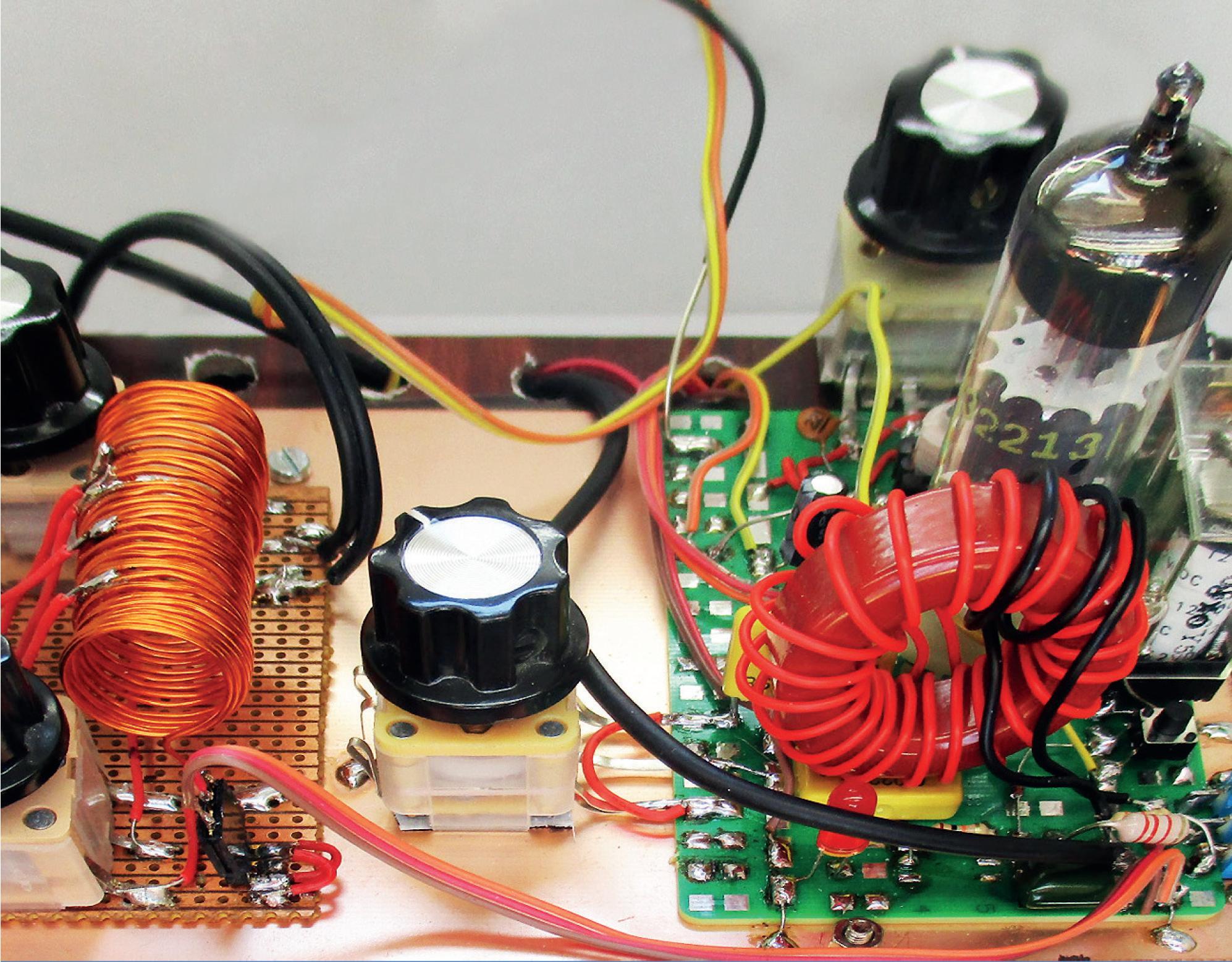
The simplest receiver you can build consists of a long length of wire for use as an antenna, a ground connection, a germanium (Ge) diode and a high-impedance headphone. The germanium diode may be difficult to source so a modern Schottky diode can be substituted. The radio needs no external power supply because the signal picked up by the antenna provides all the energy necessary, which is why it needs to be relatively long. Usually, a 10 meter length of wire will do the job. This design assumes a high-impedance headphone of 2 kΩ, but it will work just as well with a 600 Ω type. Standard low-impedance headphones of modern design are usually 32 Ω but they can also be used with a suitable transformer (see section 2.2) to provide impedance matching.
You can use any Ge diodes from type AA112 to AA144 or any Schottky diodes from BAT41 to BAT86. This simple radio is not selective, which means it receives all strong stations at the same time. Unless a strong local station is overpowering all the others, you should be able to hear some stations with fluctuating volume, especially at dusk.
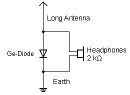
To achieve desired selectivity, a resonant circuit consisting of a coil and tuning capacitor can be added to the circuit. Using a tuning capacitor of up to 320 pF and a coil of 300 µH, will allow the entire medium-wave band can be covered. The coil consists of 90 turns of wire wound onto a 4 cm diameter cardboard roll to make the necessary air-cored coil.
This radio is not very selective and doesn’t achieve much in terms of output volume. It’s important to carefully adjust the antenna and rectifier; this can be achieved by adding tap or connection points along the receiving coil. In section 2.2, a medium wave receiver is described which uses adjustable matching.
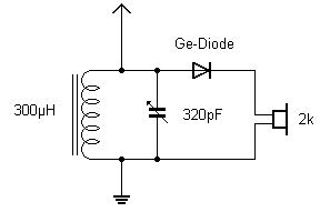
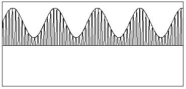
You may wonder why a diode is necessary in a receiver circuit. To answer that one you need to delve into a little bit of radio theory. A transmitter broadcasts high frequency electromagnetic waves into free space via a transmitting mast. The broadcast radiates in all directions and induces a small signal in an antenna at the receiving location. Transmitters that send on the medium wave band transfer their information, such as speech and music, in the form of amplitude modulation (AM) of the carrier frequency. The radio frequency carrier amplitude changes in time with the low-frequency (baseband) voice or music signals.
The received radio signal remains inaudible even in headphones because our ears are only sensitive to sound pressure waves up to about 20 kHz. The low-frequency signal carrying the voice and music information needs to be recovered from the radio carrier wave. This is where the diode comes in; using just one diode you can demodulate the RF signal. The average current of the rectified signal corresponds to the original modulated AF signal.
The first detector radios used crystal detectors. Lead sulfide (galena) or a piece of pyrite crystal was used for this purpose. Both are sulfur compounds and occur in nature as ores (lead ore; iron ore).

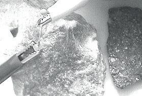
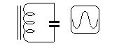
Figure 2.5 shows a crystal holder with a lead sulfide crystal from the early days of radio technology. A spiral spring made of steel wire known as a cat’s whisker contacts the crystal surface. The characteristics of the semiconductor junction formed at the crystal surface can be tested with an oscilloscope component tester. You will need to experiment a bit to find a suitable spot on the crystal surface and to recognize a typical diode characteristic curve on the component tester trace.
he crystal can be used successfully to build a diode radio. Numerous strong stations can be heard without the need for any additional amplifier. Even today, it is possible to build a detector using these natural minerals. Pyrite forms regular, gold-colored cuboid crystals in rock. Lead sulfide is black with areas of metallic shiny facets on its surface. A sewing needle can be used as the cat’s whisker detector. You will need to test various points on the crystal surface until contact achieves a good rectification characteristic.
Vintage circuit diagrams for detector radios assume that headphones shown on the circuit will be high-impedance types with 2000 Ω driver coils. These were standard back then. Nowadays a typical set of headphones will use 32 Ω driver coils which will be too low to function properly in the original circuit. You can, however, use a small transformer to provide the necessary impedance matching. A transformer salvaged from a small mains adapter can be used here. If the mains adapter has switchable taps, (3/4.5/6/9/12 V) on the secondary winding you may be able to use these to optimize the impedance match. Remove the transformer and connect the secondary winding to the headphones and the primary winding to the circuit where the high impedance phones would normally be connected.
In a diode radio, correct antenna matching is the key to success because you cannot afford to waste any of the received RF energy. The receiver coil, therefore, has several tap points. Using a total of 80 turns of 'Litz’ wire on a 10 mm diameter ferrite rod, makes sure you will be able to cover the entire medium wave band. Long antennas should be connected to a lower tap of the coil to not overly dampen the resonant circuit at the input. Try connecting the long antenna to each of the winding taps to find which one gives the best reception. Two coupling capacitors are also shown connected at the coil end. Experiment with the aerial connection, a higher value of capacitance results in stronger coupling.

For such a simple radio, a good antenna is crucial. If your house is fitted with metal rainwater guttering, this can make a good antenna. The guttering should not have a connection to ground potential. A zinc gutter will often be cemented into a drainage pipe near the ground and thereby will be insulated. All you need now is a connection wire, and that should make a really good antenna. In case the reception is still too quiet for headphones, you can connect the output to a set of PC’s active speakers.
Another good antenna is sometimes the heating system of an apartment. Although the pipes are usually grounded at some point, the total length of all the piping can effectively act as a loop antenna. In many cases, this can result in high received signal levels.

Looking at old "plans" to build detector radios, they are usually designed to receive signals from local stations in the medium wave band. These stations are becoming rarer and may even be unavailable now as more countries shut down their medium wave transmitters. Some countries such as the UK, Italy, France, and Spain however still broadcast in the band. Transmitting on shortwave has the advantage of covering much greater distances. Many countries have their own international broadcasting services designed to inform and entertain overseas listeners. The tried-and-true AM radio is, therefore, just as active on shortwave as ever.
Tuning in to higher frequencies requires smaller coils which are much easier to make. While a good medium wave coil needs a ferrite rod and a coil wound from hard-to-find 'Litz’ wire, on shortwave, you can use standard insulated copper wire. A special coil former with a ferrite core is not required; you can use any insulated wire.
For the first attempt, a coil with a total of 25 turns with four taps should be wound. I used the plastic body of a banana plug which measures 8 mm diameter but you could use a ballpoint pen body. Two holes spaced 1 cm apart help to fix the wire ends. Then, wind 5 turns, make a tap point, and apply the next turns. The finished coil connections can be soldered to a 6-way pinheader strip.
The entire radio can be built on an experimental plug board. Pins have been soldered to the variable connections so that it can be easily plugged into the prototyping plug board. The only thing missing is the diode and a headphone jack with soldered connection wires. The advantage of this construction method is that it allows for easy experimentation to try out other circuit mods.
The respective taps for the antenna connection and the diode on the coil can be experimentally adjusted. This tuning capacitor is dual gang with both halves connected in parallel. If only the upper range above 10 MHz is to be received, the lower-valued half of the tuning capacitor rated at 80 pF will be sufficient.
The radio requires a high-impedance headphone, such as a piezoceramic crystal earpiece or dynamic headphones with a 2 kΩ resistor placed in series with each capsule. Low-impedance 32 Ω types cannot be used directly and require an impedance transformer (see Section 2.2). Medium-impedance headphones with 600 Ω can also be used directly.

A germanium or a Schottky diode can be used as the detector. Both of these diodes have a low forward threshold voltage. A germanium diode also has reasonably low conductivity in the reverse direction, which is important when using a high-impedance crystal earpiece.

With a Schottky diode, the earpiece can become electrically charged like a capacitor. As the charge builds up the diode is completely reverse biased. In this case, an additional 100 kΩ resistor should be connected in parallel with the earphone to dissipate any charge build up to ground.
For best reception you need an aerial wire a good 10 m long suspended as high as possible. But even a short 3 m length of wire hooked up high up around a room will provide reasonable signal strength for initial trials. With careful tweaking of the tuning capacitor, several stations will be heard with sufficient volume, especially in the evening. Often you will hear two or three stations at the same time and tuning. The usual fluctuations in field strength on shortwave reception mean that one station may be clearer than another at different times of day. While individual radio bands are clear, nearby stations cannot be clearly separated. The selectivity of this radio design is not yet optimal.
The taps to the coil shown in the circuit diagram are only rough guidelines. Here you can try to find the optimum balance between volume and selectivity, which is easily achievable with the plug board construction method used here. The following rules of thumb apply:
• Lower taps points for the antenna and diode improve the receiver’s selectivity but reduce output volume.

• Long antennas should be connected to one of the lower tap points. Connecting to points higher up results in reduced volume and lower selectivity.
These relationships can be easily verified experimentally. Later on you will take a closer look at the theory to support these general rules.
Germanium diodes are rarely used nowadays. Silicon diodes are very popular for all sorts of applications and the 1N4148 is the most commonly used universal diode. The circuit shown in Figure 2.11 uses a silicon diode with an additional bias voltage applied. In addition, a coupling capacitor is used here to connect the signal to an amplifier input.
A silicon diode requires a forward voltage bias of around 0.5 V before any significant current starts to flow. Since the received RF signal at the resonant circuit only rarely reaches such high levels, you may not hear any recovered signal. Germanium diodes, however, have a forward voltage threshold below 0.2 V so that smaller signals can be recovered. To overcome the high threshold of silicon diodes, you can set up a small DC current of about 10 µA to flow through the diode. This will forward bias the junction allowing received signals below 100 mV to be demodulated.
Although the circuit can be operated directly with headphones, it works better with a speaker amplifier. A set of active PC speakers, for example, will work well here. The built-in audio amplifier provides sufficient amplification and a high input resistance in the order of 100 kΩ. This results in less damping of the resonant circuit and gives better selectivity. In addition, compared to using headphones, you can connect the antenna to a lower tap on the coil to improve selectivity and boost volume level.
In order to build each circuit described here we’ve provided the necessary inductance and specific measurements. However, sometimes you may need to modify the circuit or use a different coil body; in that case, you’ll need to determine the number of turns yourself. It’s also possible that you have some old coils salvaged from redundant equipment that you can modify and adapt. Regardless, it’s useful to know how to calculate coils yourself.
There are basically two types of coils: those wound on a magnetizable core (like ferrite or iron powder) and those without a core, known as air-core coils. Let’s focus on air-core coils first. For instance, a coil for a shortwave resonant circuit has 20 turns, a diameter of 16 mm, and a coil length of 35 mm. It has an inductance of approximately 3 µH and, when combined with a variable capacitor up to 300 pF, can reach a lower frequency limit of around 5.3 MHz. We’ll show you how to calculate this and introduce a simple tool that can make the process easier.
In general, the following formula applies to a long coil where l > D where n is the number of turns, A is the cross-sectional area in square meters, and l is the length in meters:

L = µ0 * n² * A / l
where the magnetic field constant µ0 equals:
4 π * 10 –7 Vs/Am = 1.2466 * 10-6 Vs/Am
This formula actually only applies to an infinitely long coil but can be used as a useful approximation up to a length of l =D. With a short coil of the same number of turns, the magnetic coupling between individual turns increases, resulting in a higher inductance. Conversely, stretching out the turns reduces inductance, which can sometimes be used to adjust coils.
The above formula can be simplified for a circular coil cross-section, where the diameter D and length l of the coil are given in mm, to the following approximation formula:
L = 1 nH * n² × D²/mm² / (l/mm)
This formula uses the approximation of π × π = 10 which introduces an error of approximately 1.3%. This is generally an acceptable simplification; you cannot expect high accuracy since the shape of the coil, especially the ratio of length and thickness, wire thickness, and even the location where the coil is mounted, all influence the final value of inductance achieved. In practice you can expect to achieve accuracy within 10% for an air-core calculation.
RF coil formers with ferrite screw cores are often used. The coil inductance increases by up to four times or more when a ferrite core is used. By changing the insertion depth of the screw-in core the coil value can be adjusted. Ferrite cores are manufactured for use with certain frequency bands in which they have lowest energy losses.
Much larger inductances can be achieved by using closed cores with or without an air gap. The air gap reduces the inductance of the coil, but allows for greater magnetization, i.e., the core itself only reaches magnetic saturation at higher currents. Common types of cores include ring cores, transformer cores in E-I shape, and closed pot cores.

The inductance depends heavily on the number of turns, the material used, and the geometry of the core. A theoretical calculation, like for the air-core coil, is not so simple. The manufacturer will instead provide an AL value in nH/n² for each type of core.
L
For example, an Amidon T37-2 ring core has an inductance of 40 µH at 100 turns, which corresponds to an AL value of 4 nH/n². Reducing the winding to 30 turns, the inductance becomes:
L = 30 * 30 * 4 nH = 3600 nH = 3.6 µH.
The ring core coil is suitable for building an RF resonant circuit, just like an air-core coil. Besides the AL value, the intended frequency range of a core is also important. The Amidon type xxx-2 has the color code red which indicates it is suitable for frequencies up to 30 MHz.
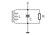
If you connect a coil and a capacitor, a resonant circuit is created. Electrical energy can oscillate back and forth between the coil and capacitor, similar to the decaying swing of a pendulum, the period of the swing indicates the resonant frequency f . The electrical circuit responds to a short pulse of current with a diminishing oscillatory voltage waveform.
The formula for calculating the resonance frequency is:
f = 1 / (2π√(L C))
Tuned circuits are often used in electrical circuits that process a range of different signal frequencies or mixed frequencies. Current and voltages that flow in such circuits will vary according to the signal frequency. The parallel resonant circuit has a complex impedance Z with a sharp maximum value at the resonant frequency f0. At this frequency, RC = RL and the currents through the coil and capacitor cancel out exactly due to their total phase difference of 180 degrees. An ideal oscillating circuit with no losses would have infinitely large impedance at the resonant frequency.
In practice however, damping of the oscillation occurs because of energy losses in the resistance of the coil wire, magnetic losses of the coil core, and electromagnetic radiation, resulting in a finite resonant resistance. To simplify you can add all the losses together and assign them as a parallel loss resistance R.
Each resonant circuit has a property called the Quality factor or just Q which is inversely proportional to the bandwidth of the circuit. Q can be easily determined when the parallel damping resistance R is related to the inductive resistance RL = 2 π f L or to the capacitive resistance RC = 1 / (2πfC) at the resonant frequency.
Q = R / RL or Q = R / RC
If a resonant circuit is excited with a constant alternating current I of variable frequency, or through an alternating current source with high internal resistance, then the resonant circuit voltage is proportional to the magnitude of the complex impedance Z. At resonance, the voltage is highest. The smaller the damping of the vibration due to energy losses of any kind, or the larger the quality of the resonant circuit, the higher the resonant voltage rises. On both sides of the resonant frequency, points on the resonance curve can be determined at which the voltage has dropped to a factor of 1 / √2 = 0.707 = –3 dB. The frequency separation of these points is referred to as the bandwidth b of the circuit. Between the resonant frequency f0, bandwidth b, and quality factor Q of the circuit, the relationship is
b = f0 / Q.
Figure 2.16 shows the characteristic resonance curves of the quality (Q) factor. At Q = 50, a larger bandwidth b1 results than at Q = 110 with bandwidth b2. At the same time, an increasing resonance peak is observed at higher quality. This causes the resonant circuit to oscillate more strongly at the resonance frequency. However, far away from the resonant frequency, the resonance curves show little difference in their response.

The damping of the circuit, and therefore its quality, is practically always caused by intrinsic series and parallel resistances. The series resistance is due to the wire winding, but for a certain frequency, it is greater than the DC resistance due to the skin effect. The parallel resistance is determined by the connection impedance in the circuit. However, an iron or ferrite core also has losses that can be represented by a parallel resistor. With the same inductance, a coil with a core requires fewer turns and therefore incurs lower copper losses. At the same time there are now losses in the core to consider. At very high frequencies of around 100 MHz, pure air coils made of thick, silver-plated wire perform better, while at medium frequencies of around 10 MHz, the best quality is achieved with a closed core such as a toroidal core. Air coils, on the other hand, are an alternative down to about 1 MHz. Coils and transformers used in the audio frequency range, however, are almost always built with a core.
You can expect to get a quality factor Q of up to 100 by being careful with coil construction. A resonant circuit is however also damped by the external circuitry to which it is connected to or by an antenna. This damping effect can to some extent be mitigated by ensuring a loose coupling of the resonant circuit by using a small auxiliary winding, a tap point on the coil, or a suitable coupling capacitor. When a coil connects directly to the input of an amplifier, its input impedance should be very high to lessen the damping effect.
A small Visual Basic program can be found on the author’s website called LCFR which has been written to simplify the calculation of coils and resonant circuits. The program calculates the inductance of air coils and coils with a known AL value. In addition, the resonance frequency, and the inductive resistance RL of the coil at this frequency can be determined if a value of capacitance is given in addition to the inductance. The program consists of a user interface made up of three independent calculation areas for practical reasons. Air coils can be calculated in the top section and coils with cores in the middle. At the bottom, you will find a calculation of the resonance frequency and the inductive resistance. Any change in the input variables immediately updates the output result. The last calculated inductance of a coil is automatically transferred to the lower calculation. The program is useful for quickly trying out new parameters. The displayed three decimal places for the inductance value should not be interpreted as an indication of the calculation accuracy but makes it simpler to show the calculation of coil characteristics in a wide range from a few nH (1 nH = 0.001 µH) to many mH (1 mH = 1000 µH).
Radio frequency (RF) technology is one of the areas which still allows putting your own ideas into practice. Countless circuit variants with special objectives allow space for meaningful experiments and projects. Many things simply aren’t available off the shelf. Crystal detector radios without their own power source, simple tube receivers with a touch of nostalgia, the first reception attempts at Software Defined Radio, special receivers for amateur radio, all this can be realized with little effort and as a perfect introduction to RF electronics.
For a long time, radio construction was the first step into electronics. Meanwhile, there are other ways, especially via computers, microcontrollers, and digital technology. However, the analog roots of electronics are often neglected. Elementary radio technology and easy-to-do experiments are particularly well suited as a learning field for electronics because you can start with the simplest basics here.
But the connection to modern digital technology is also obvious, for example, when it comes to modern tuning methods such as PLL and DDS or modern DSP radios.
This book aims to give an overview and present a collection of simple RF projects. I would like to support you to develop your own ideas, to design your own receivers and to test them.
Burkhard Kainka (1953)
— ham radio operator with the callsign DK7JD, worked for many years as a physics teacher. Since 1996 he is an independent developer and author in the fields of electronics and microcontrollers. Burkhard runs the websites www.elektronik-labor. de and www.b-kainka.de, with his contributions to the Hobby Corner and a general fondness for the basics of electronics.