22 minute read
Fernando Rueda
KEY COMPONENTS IN ITER. ENGINEERING PRINCIPLES TO GUIDE NON-CONVENTIONAL DEVELOPMENTS
Fernando Rueda (ESTEYCO Mechanics)
Advertisement
Fernando Rueda (ESTEYCO Mechanics)
INTRODUCTION
We all normally talk about ITER or the ITER project. However, it would be sometimes more appropriate to talk about the ITER projects, to make more visible the amount of different, unique and extremely complex systems that, all together, make up ITER. ITER is divided into a set of systems as defined by the ITER Plant Breakdown Structure (PBS), the hierarchical breakdown of the ITER Plant. The PBS has five levels (Levels 0 to 4), each one representing a specific hierarchical step. These systems are designed to work in a coordinated manner. The role of interfaces and interface management is crucial for the global success of the project, and a considerable proportion of the engineering challenges to be solved have to do with interfaces. In most cases, ITER systems are one of-a-kind developments involving multimillion-euro programmes and years, if not decades, of intensive work by scientists, engineers and technicians, ranging from scientific research to advanced engineering developments, huge integration efforts and, quite often, novel manufacturing techniques, processes and/or materials. Many different physics are involved, but here the focus is on the thermal and mechanical parts. Depending on their location and functionalities, the thermal-mechanical design of these systems may be driven by a variety of aspects, a few of which are summarised in the following section.
SOME ASPECTS DRIVING THE THERMAL-MECHANICAL DESIGN OF SYSTEMS IN ITER
Some design-driver aspects of many ITER components are strongly linked to the (often singular) nature and (often overwhelming) magnitude of the loads experienced by and within the ITER Tokamak machine. Understanding loads in ITER is a discipline in itself. In addition, there are other constraints, not directly linked to withstanding loads, which are also critical in terms of both local component design and global project integration. Some of these are briefly outlined after the intro-
duction on the loads in ITER, which, for the purposes of this short discussion, are divided into thermal, electromagnetic, gravity, pressure and seismic loads. Thermal loads and requirements show many different and sometimes contradicting faces in ITER, since ITER will generate the greatest temperature gradient in the world (and probably elsewhere): from the 150 million°C of the plasma to –269°C of the superconducting magnets in about 3 metres. • On the ‘hot’ side of things, thermal aspects are clearly relevant for plasma-facing components directly exposed to plasma radiation and components subjected to intense nuclear heating generated by the 14MeV neutrons resulting from the fusion reaction, and being gradually slowed down by the components on their way out from the plasma. Specific components of plasma heating systems (Neutral Beam Injector and electron or ion cyclotron antennas) also suffer important heat fluxes and must meet strict thermal constraints, even if not directly affected by the two previously mentioned sources of loading. • On the ‘cold’ side of things, the cryogenic nature of the superconducting magnets results in completely different problems and approaches that critically affect global and high-level plant architecture decisions, such as the conceptual design of the Tokamak machine support structure. From a mechanical design perspective, trying to adapt to significant thermal gradients while achieving the required mechanical capacity to withstand other relevant sources of loading in various forms (coolant pressure, gravity, electromagnetic transient forces, etc.) is one common challenge for many key ITER components. This challenge materialises into an extremely wide variety of solutions adapted to each problem specificities. Electromagnetic effects and loads are also a very relevant and singular aspect that drives the design of not only the magnets, but also many key ITER components surrounding the plasma and including the vacuum vessel itself. These effects can be divided into:
• Slow transients, which mainly act on the magnet system due to the interaction between the strong ITER magnetic field and the electrical currents flowing through the different conductors.
Fernando Rueda (ESTEYCO Mechanics)
Fast transients, which will occur in ITER when certain events take place, such as plasma disruptions (rapid loss of the plasma thermal energy and current derived from a loss of confinement and impurity influx) or plasma vertical displacement events (loss of the vertical position control of the plasma as a result of a failure in the feedback control system). These transient events induce electrical currents in the conducting structures around the plasma, which, in turn, generate significant internal body forces in the structures from the (mutual) interaction with the ITER magnetic field. The duration of these events is around a few tens of a millisecond and are therefore mostly seen as impulsive loads in the affected components. The induced internal forces can be very high and absolutely drive the design, not so much of the components themselves, but of their supporting structures (these that very often have to be flexible as well to accommodate significant thermal expansions/contractions). The derivation of these internal forces must consider the potential dynamic amplification due to inertial effects, which can be high for components that would be normally considered as stiff (frequencies above 30Hz) in other contexts.
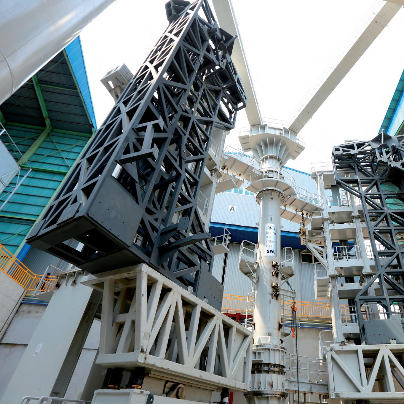
Gravity is also important. And we engineers are glad this has been a very wellknown force since ancient times and that the associated uncertainties are extremely low when compared to other sources of loading in ITER. The Tokamak machine is a very heavy system, with a total mass of over 23,000 tonnes, 10,000 tonnes of which is the magnet system, 8,000 tonnes is the vacuum vessel, and 3,800 tonnes is the cryostat. Though not particularly relevant for many Tokamak machine internals, the action of gravity is clearly dominant when it comes to both the design and manufacturing of the Tokamak machine supporting structures, and to the full installation and assembly of the machine, for which special tooling and auxiliary means are required in order to handle such large masses while respecting tight positioning tolerances (see Figure 1). Pressure loading affects the design of a wide variety of cooling circuits and associated piping and manifolds. Some components must comply with the European pressure directive and/or the French regulation on nuclear pressure equipment. At a larger scale, it is worth mentioning that the effect of vacuum is only a relevant loading for the two large vacuum chambers of the Tokamak machine. In
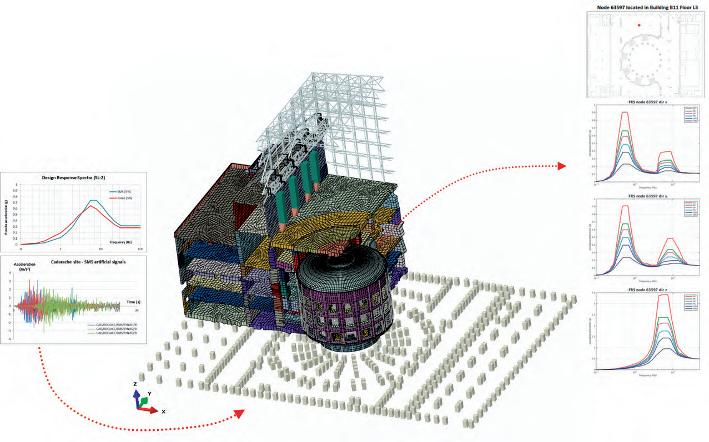
particular, and because of the global Tokamak machine supporting scheme, the effect of vacuum on the cryostat implies a 25% reduction in the gravity reaction loads on the support structure of the Tokamak machine: a non-negligible effect equivalent to around 5,000 tonnes. As a nuclear facility (this will be addressed later on when briefly discussing nuclear safety aspects), the seismic design of ITER must ensure that the corresponding seismic safety requirements are met according to the French regulation. The ITER investment protection policy also sets out some requirements on the seismic capacity of the facility and, subsequently, its systems and components. The Tokamak Complex hosting the Tokamak machine is one of the largest seismically isolated structures ever built, with on plan dimensions equivalent to those of a standard football stadium, more than 70 metres high and an estimated mass of over 350,000 tonnes. The seismic isolation design effectively limits horizontal responses by filtering seismic ground motions, but vertical ground motions are directly transmitted (and amplified by the dynamic
Fig. 2. ITER seismic floor response spectra.
Fernando Rueda (ESTEYCO Mechanics)
response of the building as we move upwards) to the Tokamak machine and the components inside. An illustration of the ITER seismic floor response spectra generated by ESTEYCO is shown in Figure 2. As long as components are relatively stiff (frequencies above 10Hz), seismic constraints are easy to handle in most cases. This is the case for all in-vessel components and most of the systems supported by the Tokamak building. However, the natural frequencies of main natural vertical/rocking modes of the Tokamak machine are estimated to be in the 5-10Hz range, resulting in non-negligible seismic loads that must be accounted for and addressed from a design perspective. Despite the seismic isolation of the facility, the design of other relevant systems is also largely influenced by seismic loads, and this helps in understanding why a seismically isolated solution was adopted for the Tokamak Complex. There will be many difficulties to face in the future design of the adjacent, non-seismically isolated Hot Cell Complex, which will support the operation, maintenance and decommissioning of the ITER Tokamak. As already mentioned, there are many other aspects that are not related to the loading of the components from a thermal-mechanical point of view, which affect potential design solutions and, in many cases, become significant constraints. Vacuum requirements are clearly one such constraint. ITER has two of the largest vacuum chambers in the world: the vacuum vessel and the cryostat (around 2,000m3 and 8,500 m3 of volume under vacuum, respectively). The air is evacuated out of these chambers until their internal pressure is reduced to up to one millionth of normal atmospheric pressure. In addition, there are some other auxiliary systems and parts –extensions of these two chambers in terms of volume– subjected to the same requirements regarding high quality vacuum. Generating, monitoring and ensuring the extremely high vacuum levels required for plasma operation impose a number of constraints in the design of the systems. These range from candidate materials and welding processes to adequate connection techniques between mechanical parts, penetrations, quality control, etc. Every mechanical connection between parts under ultrahigh vacuum must be continuously monitored by the leak monitoring system in order to detect potential leaks.
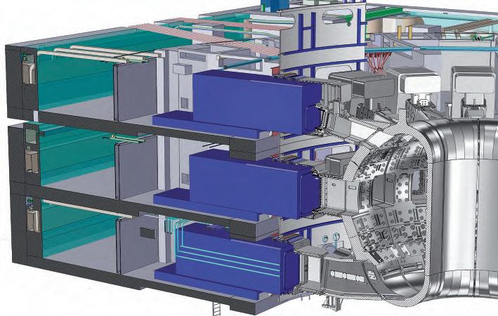
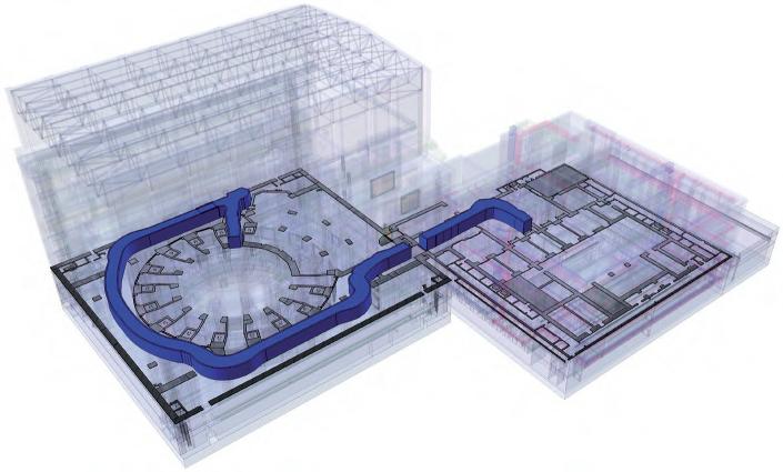
Fig. 3. ITER Cask and Plug Remote Handling System (©Fusion for Energy).
Fernando Rueda (ESTEYCO Mechanics)
Another important aspect, not so common in Big Science, and with an important impact on design and manufacturing activities is that of nuclear safety. ITER is declared a nuclear facility #174 (in French INB) and it is therefore governed by French nuclear regulations. The principal safety functions in ITER are the confinement of radioactive material –with the vacuum vessel acting as the first confinement barrier– and the limitation of internal and external exposure to ionising radiation, for which the implementation of effective shielding measures is one of the key factors. These confinement and limitation of exposure safety functions clearly determine the design of many Tokamak machine systems that are, as a result, declared as protection important components (PIC) and whose design and manufacturing procedures become directly affected by nuclear safety policies. Maintainability and remote handling must be also considered. Many of the in-vessel components will need maintenance and/or replacing during the life of ITER. Although no radioactive products are produced by the fusion reaction itself, the core of the Tokamak machine will be activated in the nuclear operation phase and all maintenance operations of irradiated components will have to be carried out by remote handling (RH) means. This is a particularly relevant constraint for the design of most large in-vessel components, such as the divertor cassettes or the port plugs that will be briefly described later on, since their supports and connections with other systems such as cooling services will have to be RH compatible. Tight positioning tolerances on components weighting up to 50 tonnes will have to be achieved on as-short-as-possible RH operations in order to reduce shutdown periods and to make the most of the ITER experimental campaigns. Components removed from the vacuum vessel through the corresponding openings will be driven out of the Tokamak building by remotely-operated containers, known as casks, for refurbishment in the adjacent Hot Cell Complex (see Figure 3). Casks will provide confinement for the activated parts being transported.
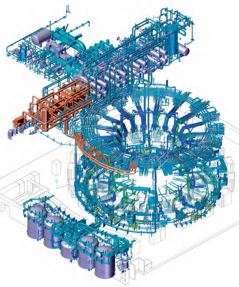
Fig. 4. ITER Tokamak Cooling Water System – TCWS 2012 design (©ITER Organization).
Fernando Rueda (ESTEYCO Mechanics)
Fig. 5. Hypervapotron cooling solution in ITER Blanket Module fingers.
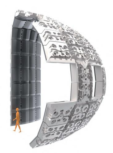
Fig. 6. ITER Blanket modules – General view (©ITER Organization). QUICK OVERVIEW OF SOME OF THE MOST RELEVANT COMPONENTS IN ITER
What follows is a very quick overview of some of the most relevant components in ITER, moving gradually from inside the vacuum vessel, directly facing the plasma, to the outside, and trying to focus on the specificities that drive each design from a thermal and mechanical point of view. The so-called plasma-facing components (PFCs) are those directly exposed to the plasma radiation and therefore subjected to the most severe thermal load conditions on the ‘hot’ side. The design of these components is largely driven by thermal considerations.
• First, active cooling must be provided, and efficient heat transfer paths implemented in the design in order to keep temperatures in the materials involved within acceptable limits. ITER PFCs are cooled by water supplied by the TCWS (Tokamak Cooling Water System, see Figure 4). Greater cooling effectiveness normally requires increasing heat transfer coefficients between the component and the coolant, which, once the coolant and inlet temperatures are fixed, can be only achieved with higher mass flow rates and/or by dedicated channel designs such as the ‘hypervapotron’ concept, where enhanced cooling performance is achieved by internal fins and local boiling (see Figure 5). Then, reducing temperature levels and associated thermal stresses requires fa-
cilitating the transfer of heat between the locations where power is deposited and the actively cooled surfaces. This can be summarised as reducing distances between heat sources and sinks and increasing the thermal conductivity of the materials in between, for which specific copper alloys with a very high thermal conductivity and improved mechanical properties are normally implemented in most ITER PFCs. Reducing distances and improving thermal conductivity are simple statements that become real challenges when it comes to the practical implementation of reliable solutions. These must take into account a number of several non-conventional manufacturing aspects, such as joining of dissimilar materials.
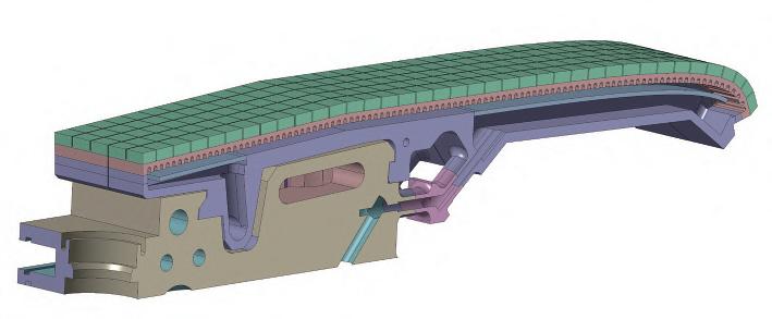
• Secondly, mechanical design solutions must be envisaged so that unavoidable thermal expansions do not induce too high thermally-induced stresses that could jeopardise the structural integrity of the components. This includes fatigue life, since it must be remembered that ITER is a pulsed machine. In addition to thermal aspects, plasma-facing components must also withstand high electromagnetic loads induced under fast transient plasma events expected to take place during ITER operation. These loads have to be carefully assessed, which is normally addressed by complex electromagnetic simulations of such transients. Appropriate supporting schemes to the vacuum vessel must be devised and implemented in order to ensure the integrity of these connections. Since these components must be maintainable and/or replaceable by remote handling systems, that also imposes additional constraints on the design. Most of the inner surface of the vacuum vessel (around 600m2) is covered by the blanket modules (see Figure 6), a set of 440 actively cooled, complex ‘bricks’ attached to the vacuum vessel that absorb plasma radiation, contribute to the thermal and neutron shielding of the components behind and constitute the primary interface to the plasma defining the plasma boundary during limiter operation and plasma start-up/ramp-down. The design of the plasma-facing part of the Blanket Modules (see Figure 7) is driven by the high heat fluxes that have to be accommodated, ranging from 1-2MW/m2 up to 5MW/m2 at some specific locations inside the chamber. The design is based on a set of toroidal ‘fingers’ (see Figure 7) to reduce eddy current-re-
Fernando Rueda (ESTEYCO Mechanics)
Fig. 7. Blanket module First Wall panel (©Fusion for Energy).
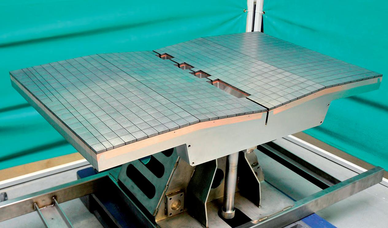
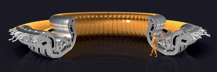
Fig. 8. ITER Divertor – General view (©ITER Organization).
lated loads as well as to limit thermally induced stresses during operation. These fingers are actively cooled by water flowing through stainless steel cooling pipes embedded into a highly thermal conductor material (CuCrZr copper alloy). This is needed to improve the heat transfer from the plasma-facing surface to the coolant. Beryllium tiles protect the copper alloy and minimise plasma contamination. All fingers are supported by a central stainless steel support beam that serves as the coolant manifold. This support beam is in turn connected to the rear part of the module, the shielding block, which is then connected to the vacuum vessel by four flexible rods and a set of shear keys designed to withstand the high transient electromagnetic loads expected under some plasma events during ITER operation. At the bottom part of the vacuum vessel, the divertor (see Figure 8) is in charge of extracting heat and ash produced by the fusion reaction, minimising plasma contamination and protecting the surrounding walls from thermal and neutronic loads. A 3D CAD global view of one divertor cassette within the vacuum vessel environment is shown in Figure 9. The divertor is divided in 54 divertor cassette assemblies consisting of: • The cassette body (see Figure 10), which provides the connection to the vacuum vessel through the inner and outer divertor rails, mechanically supports the PFCs and serves as the manifold for the coolant feeding of the PFCs (water received from and returned to the divertor PHTS through two radial pipes).
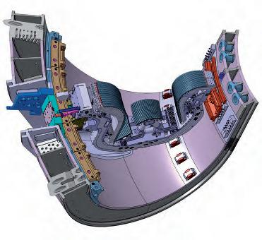
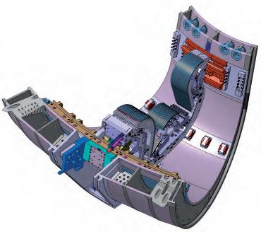
Fig. 9. DIvertor cassette within VV environment – 3D CAD model.
Fernando Rueda (ESTEYCO Mechanics)
Fig. 10. ITER Divertor Cassette Body (©Walter Tosto).
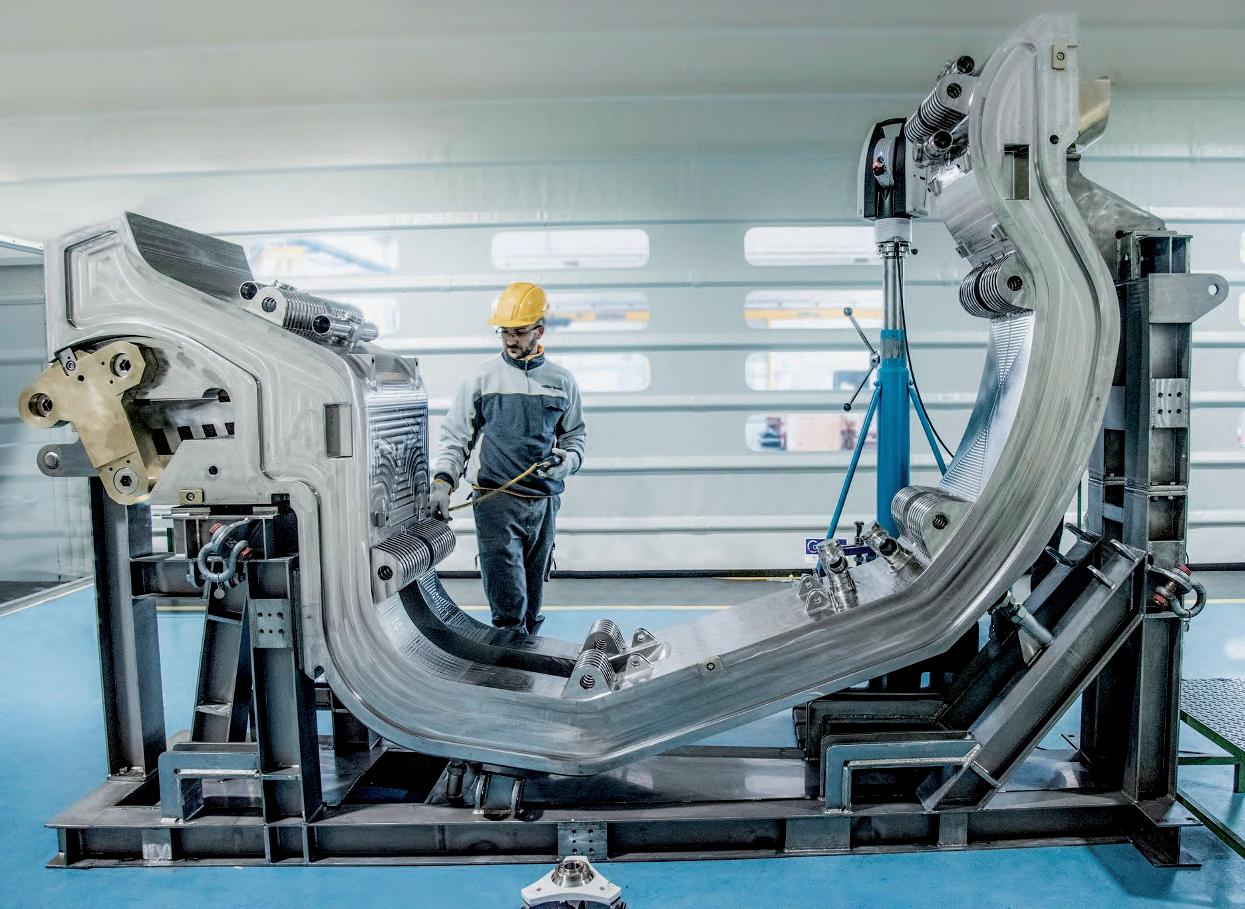
Fig. 11. ITER Divertor Inner Vertical Target (©Fusion for Energy).
Fernando Rueda (ESTEYCO Mechanics)
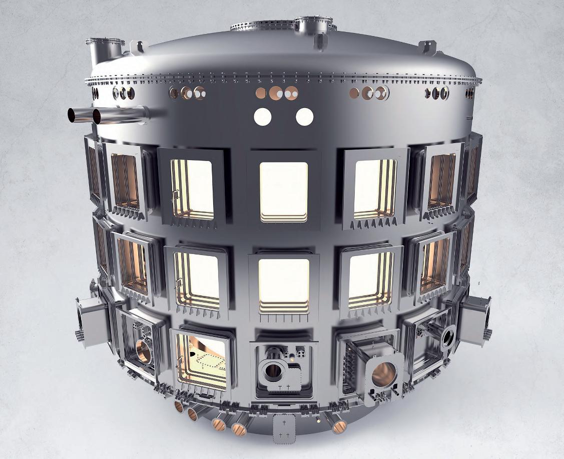
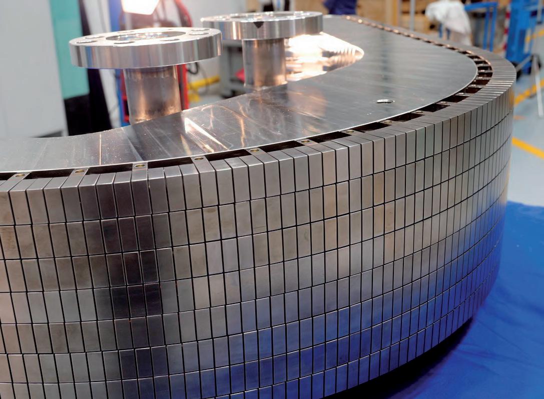
Fig. 12. ITER Vacuum Vessel – General view (©ITER Organization). • Three plasma-facing components (see Figure 11): the dome and the inner and outer vertical targets, which have to withstand the highest heat fluxes in the machine, with values of up to 20MW/m2. Conceptually speaking, the cooling scheme is not very different from that of the Blanket Module family subjected to highest heat fluxes. In this case, small tungsten blocks are directly facing the plasma, with pressurised water flowing underneath through a circuit of copper alloy pipes. The PFCs are attached to the cassette body via a set of lugs and pins, in a key example of complex joint design that is to withstand significant mechanical loads (especially during fast transient electromagnetic events) while allowing for a relatively free differential thermal expansion of the parts connected. The Blanket modules and divertor cassettes are both supported by one key ITER component, the vacuum vessel, a general view of which is shown in Figure 12. The vacuum vessel is a double-walled, stainless steel vessel in a torus shape that provides an ultra-high vacuum environment for the plasma and constitutes the first ITER confinement barrier. It also contributes to plasma stability as briefly discussed by Fabio Villone in his extraordinary introduction to magnetic confinement.
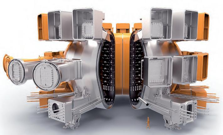
The volume in between the inner and outer shells is filled with coolant water fed by the Primary Heat Transfer System (PHTS) and thousands of in-wall shielding blocks that are essential for radiation shielding of the systems behind. Not much of the vacuum vessel main body design is driven by pure structural considerations, at least when compared to other ITER components. Due to its high mass, gravity and, in particular, seismic loads are probably the most significant, especially for the nine lower ports that rest on the corresponding gravity supports. These supports are designed so that vacuum vessel thermal expansions due to temperature increments under plasma operation (100°C) and baking (200°C) are not constrained by rotational sliding of the so-called primary and secondary hinges, as otherwise reaction loads would be impossible to accommodate. Without the vacuum vessel on top of them, the supports are a mechanism in the radial direction due to their rotational sliding capability, an inherently non-linear response that has been characterised by experimental scale-tests and advanced non-linear numerical modelling of the assembly. These numerical models have been used to understand and quantify the complex redistribution of loads seen by the highly non-linear system for increasing load levels (see Figure 13). Forty five openings, or ports, arranged toroidally in three different levels (eighteen upper and equatorial, and nine lower) to provide access for remote handling operations, diagnostics, heating, and vacuum systems. Since these ports host many of the main technological developments in ITER, each one of them can be considered a world of its own (see example in Figure 14 for equatorial port #16, housing the European TBM sets, more details of which are provided by Yves Poitevin at all in his extraordinary overview of the European TBM programme). The ‘micro world’ (45 tonnes) of port plugs and what is contained inside often faces thermal-mechanical design and integration challenges comparable to, if not superior to, those faced by the vacuum vessel itself. Port plug structures are cantilevered towards the plasma from the rear bolted flange of the vacuum vessel port extension and normally include:
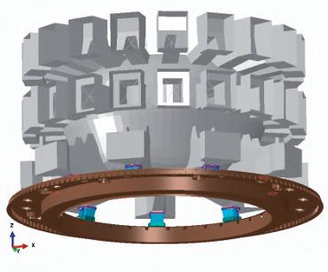
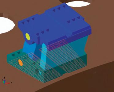
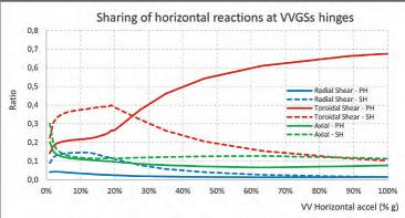
Fig. 13. Non-linear finite element modelling of the coupled VV – VVGSs static and dynamic response.
Fernando Rueda (ESTEYCO Mechanics)
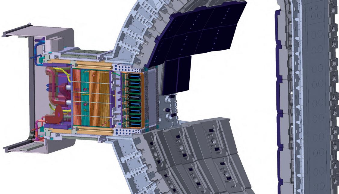
Fig. 14. ITER in-vessel ports – Equatorial port #16
Fernando Rueda (ESTEYCO Mechanics)
1. plasma-facing parts, subjected to plasma radiation and neutron loading like the blanket modules and divertor described before,
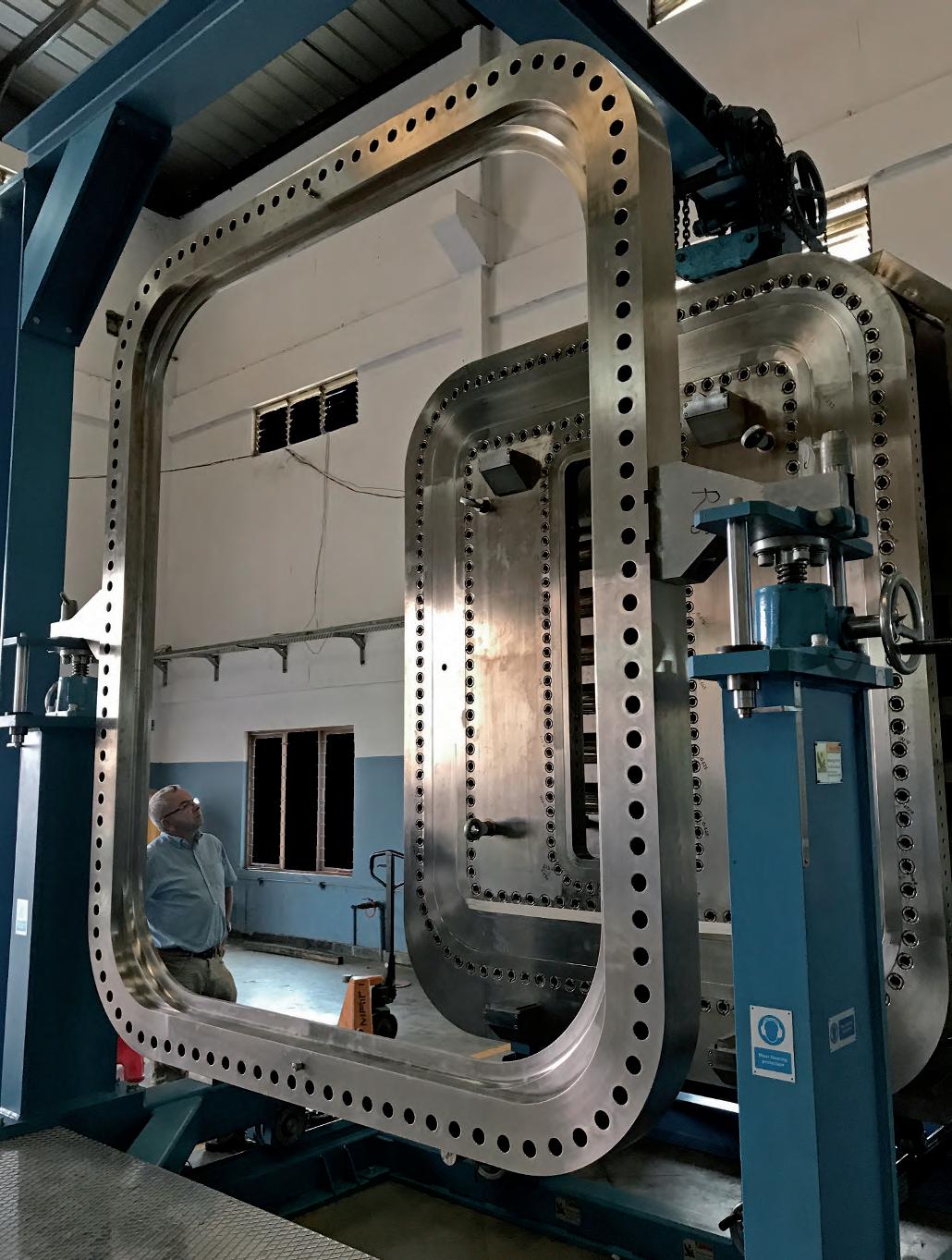
2. a central shielding (plugging) part, where shielding is normally implemented by a clever distribution of stainless steel and water arranged so that complex penetrations and services such as cooling and instrumentation can be routed through it, and 3. a rear part where a large, bolted connection to the vacuum vessel port extension is implemented. These are ultra-high vacuum connections, part of the first confinement barrier and subjected to remote handling requirements since the port plugs must be mounted and dismounted by remote handling means (not an easy task given their size, see Figure 15).
Port Plugs therefore combine a number of specificities and constraints that make the design of each one of them an actual challenge from many points of view. Port plugs must address the two main ITER safety functions; confinement of radioactive material (at the rear connection with the vacuum vessel port extension) and limitation of internal and external exposure to ionising radiation, which is achieved by efficient nuclear shielding. The need to block straight lines of passage for high-energy neutrons is one of the main design constraints for all port plugs. Routing of coolant and services must adopt relatively complex geometries to avoid neutron streaming. In addition, gaps between the external envelope of the port plug and the internal surface of the vacuum vessel port extension must be kept to a minimum, with the implementation of steps or doglegs, in order to limit straight escape routes for neutrons. This imposes challenging limitations since port plugs are to be introduced and extracted from the vacuum vessel by remote handling methods that have to move and position this 45 tonne cantilevered mass with extreme precision. From a thermal point of view, plasma radiation and nuclear heating sources must be removed by active cooling. This is usually more complex to handle in the plasma-facing part of the port plug. Thermal and mechanical design measures have to make sure thermal gradients between the front (i.e. plasma-facing) and rear parts of the plug do not induce significant thermal stresses.
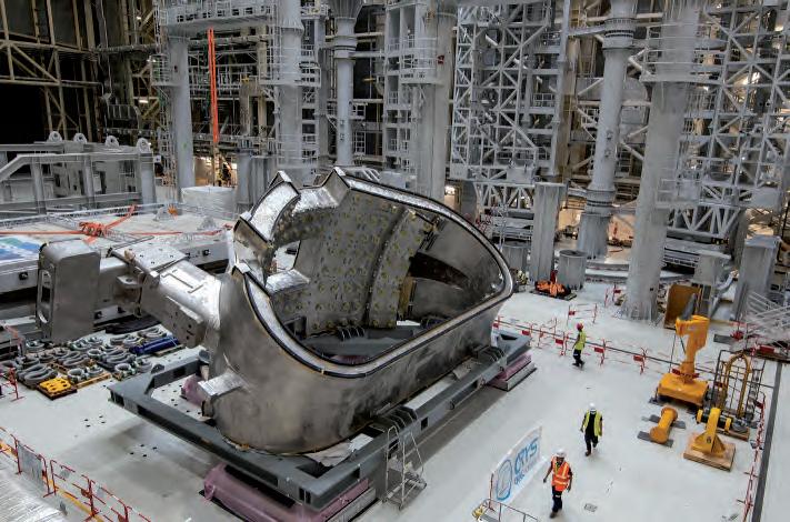
This is usually addressed by implementing some sort of intermediate mechanical connection between the front and rear parts. In some cases, and due to the pulsed operation of ITER, the thermal response of the system does not reach steady state conditions during the pulse and significant gradients due to the different thermal inertias of the front and rear parts can develop at intermediate stages of the pulse. From a global mechanical and structural point of view, the port plugs are relatively stiff cantilevered systems, with frequencies normally above 30Hz, but the loads they are subjected to are complex. In particular, some fast electromagnetic transients have a duration prone to excite inertial effects of the port plug, which can result in significant dynamic amplifications. The nine VV sectors are manufactured by Europe and South Korea. The first ones, provided by the Korean domestic agency, have been already shipped to the ITER site (see Figure 16).
Fig. 16. First Vacuum Vessel sector in the ITER Assembly Hall (©ITER Organization).
Fernando Rueda (ESTEYCO Mechanics)
Fig. 17. First Japanese Toroidal Field Coil produced by Toshiba Energy systems & Solutions – Poloidal Field Coil #5 produced by Europe – First Central Solenoid module by US ITER & General Atomics (Photographs ©ITER Organization and ©Fusion for Energy).
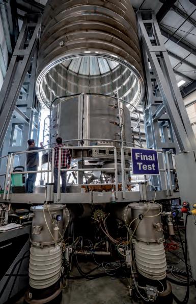
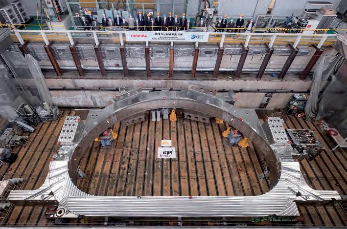
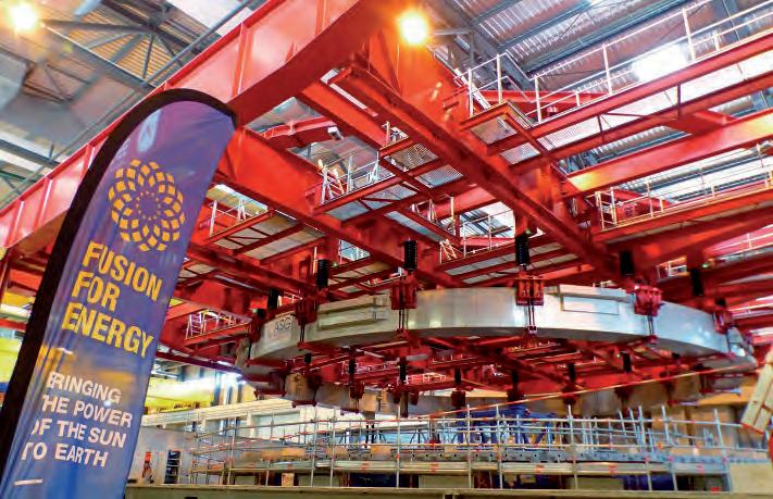
The ITER magnet system (see Figure 17) is an extremely complex assembly of superconducting magnets, in charge of producing the magnetic field required to confine, shape and control the plasma. More details are provided by Alfredo Portone in his excellent introduction to the ITER magnet system. Both the magnet system and the vacuum vessel are contained inside a larger stainless steel vacuum chamber (around 30m external diameter and 30m high), the cryostat (see Figure 18), that provides an ultra-cool vacuum environment for the magnets to operate. This is another key component of the Tokamak machine, which is also in charge of transferring the huge loads from the vacuum vessel and magnet system to the building. More details about this key and unique part of ITER are provided by Guillaume Vitupier, in his excellent overview of the ITER Cryostat. It must be also mentioned that in-vessel systems are connected to the outside of the Tokamak machine, since they need cooling, power and cryogenic supplies, routing for instrumentation, etc. These connections must be compatible with ultra-high vacuum requirements, penetrate nuclear safety confinement barriers, adapt to relative motions between the machine and the building due to thermal, electromagnetic and seismic events and, in many cases, be mounted / dismounted by remote handling means. One might think little is left in ITER for R&D activities and challenging engineering design work outside the boundaries of the Tokamak machine, but this is not the case at all. In fact, many of the most technologically complex level 1 systems of the ITER PBS almost ‘only touch’ the Tokamak machine very locally: they supply things to or from the machine (coolant, cryogenic fluids, heating, instrumentation signals). A number of unique systems are thus located on the other side of the fence, but this we will discuss in a future book… A glimpse of what can be found outside Tokamak machine boundaries and the associated complexities is provided in the description of the Tokamak machine supporting structure covered in a separate chapter.
Fernando Rueda (ESTEYCO Mechanics)
Fig. 18. ITER Cryostat – General view (©ITER Organization).
