26 minute read
Enrico Di Pietro


JT-60SA – A PATHFINDER FOR ITER AND DEMO Enrico Di Pietro (Fusion for Energy)
The Japan Tokamak 60 Super Advanced (JT-60SA) is a follow-up of the successful JT-60U incorporating a fully superconductive magnet system for plasma confinement. At the same time, JT-60SA shall act as a test bed for future plasma scenarios in ITER. The mission of the JT-60SA project is therefore to contribute to the early realization of fusion energy by its exploitation to support the exploitation of ITER and research towards DEMO, by addressing key physics issues for ITER and DEMO. In particular, JT-60SA will allow: • To confine break-even equivalent class high-temperature deuterium plasmas. • Exploration of configuration optimization for ITER and DEMO with a wide range of plasma shapes and aspect ratios including that of ITER, with the capability to operate in both single and double null configurations. • Exploration of ITER relevant high density plasma regimes well above the
Advertisement
H-mode power threshold with ∼40MW high power heating. • To study power and particle handling at full power for 100 s with top and bottom water-cooled divertors compatible with maximum heat flux of 15 MW/ m2. In the initial phase only the lower divertor will have high heat flux capability. • Exploration of full non-inductive steady-state operation with 10MW/500keV tangential Neutral Beam Current Drive and 7MW of Electron Cyclotron
Current Drive.
• Exploitation of high beta regime with stabilizing shell covered with plates and internal RWM stabilizing coils and high power heating and current drive system.
The design of the JT-60SA device does not aim at tritium operation, restricting the nuclear requirement on the design, and simplifying operation by allowing access between experimental campaigns. The main parameters of JT-60SA are shown in Table 1.
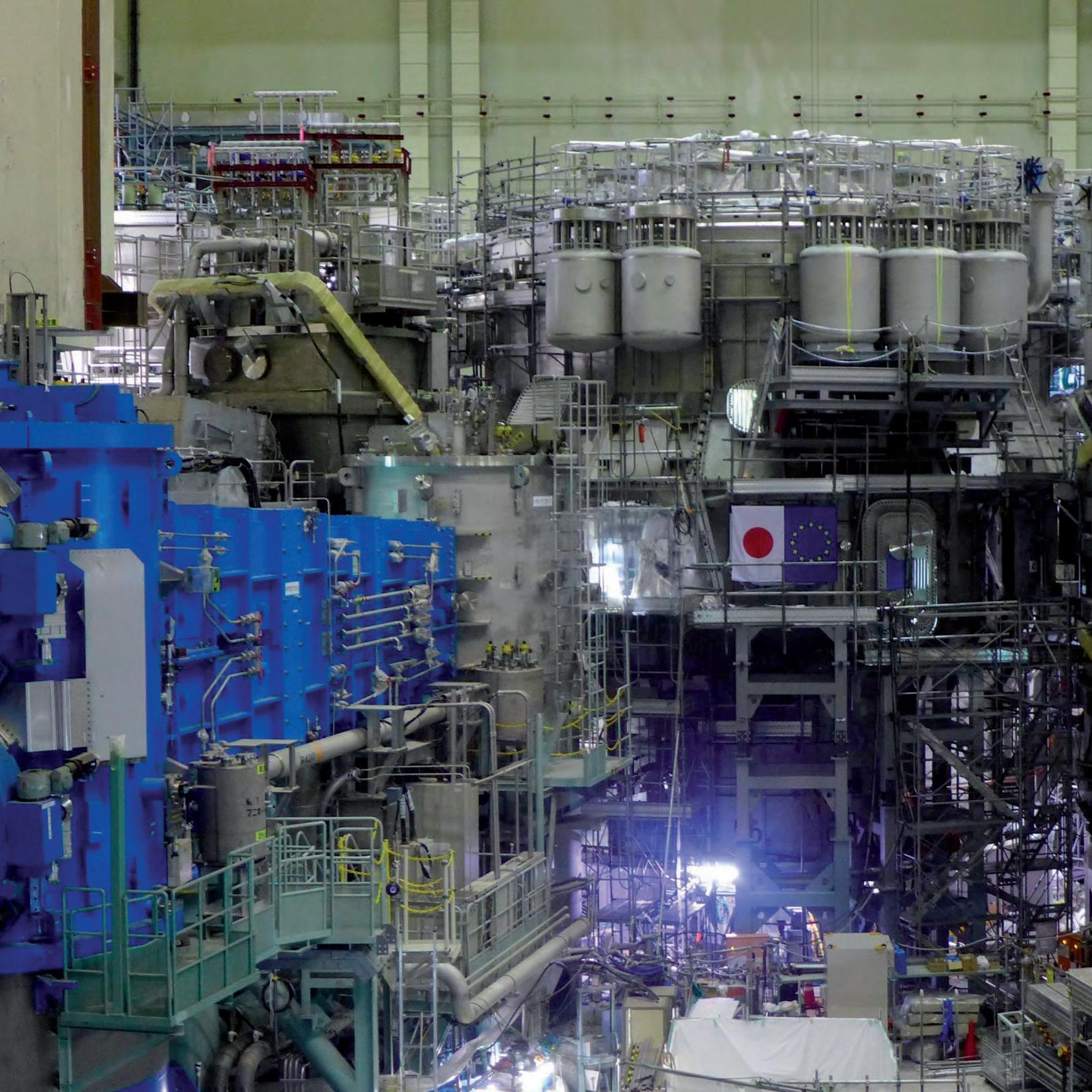
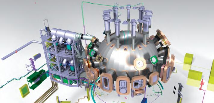
A bird’s eye view of JT-60SA is shown in Figure 1.
Parameter
Major plasma radius Minor plasma radius Plasma current Maximum magnetic field on axis
Plasma heating techniques
Plasma thermal energy Maximum plasma pulse length Cold mass of magnets,structures and thermal shields
Table 1. Main Parameters of JT-60SA.
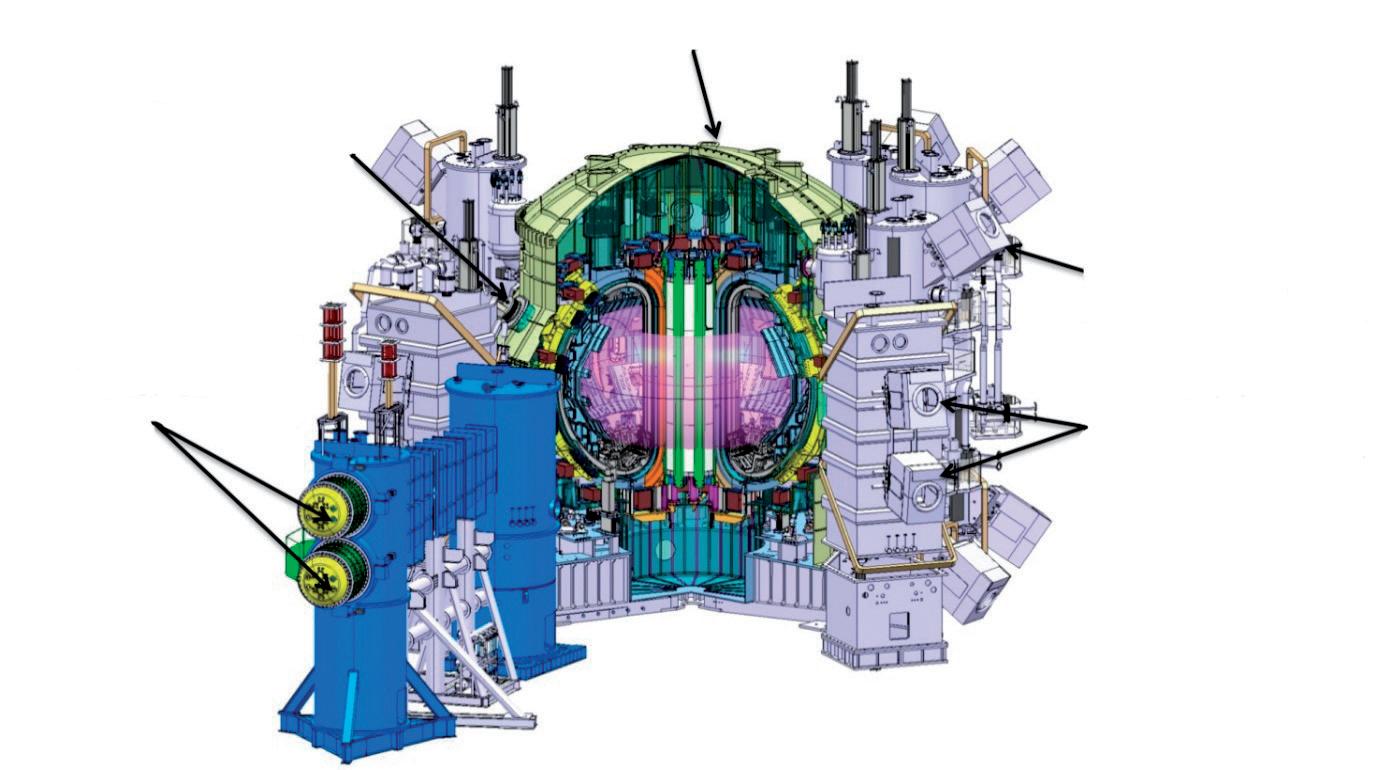
ECRH Launcher
N-NBI ion Source
Dim JT-60SA
m 3.0
m MA T
MW
MJ
s t
1.1 5 2.25 NBI: 34 MW ECRH: 7 MW 22 100 734
Cryostat
Fig. 1. JT-60SA general view. Perpendicular P-NBI ion Source
Tangential P-NBI ion Source
3 [s/m
E t
(0)
D n
1021
1020
1019
Break-even condition
JT-60SA
KSTAR
FTU
C-Mod Ignition condition
ITER
DEMO
JT-60U
JET DIII-D TFTR
EAST
107
108
Ti(0) [K]
109
Fig. 2. Planned operation range of JT-60SA compared to other tokamak projects. (nD(0)=plasma central ion density, τE =energy confinement time, Ti(0)=plasma central ion temperature). Its performance range, compared to other experiments worldwide, as well as with expected ITER and DEMO operation, is shown in Figure 2
MAGNET SYSTEM
For optimum plasma confinement, the magnetic cage must enclose the hot ionized particles at a short distance to keep the magnetic induction high while reducing the size of the coils and the amount of superconductor. At the same time, the magnetic ripple must be kept small to avoid a loss of hot plasma to the wall. This challenge is met by a symmetric arrangement of eighteen D-shaped Toroidal Field (TF) coils.
The TF fields alone are not sufficient to confine the plasma for extended periods. A strong current through the plasma twists the trajectory of the hot ionized particles stabilizing it. This plasma current is of the order of several mega-amperes and is induced by a set of four Central Solenoid (CS) modules arranged along the central axis of the TF coils. In addition, six circular shaped Equilibrium Field (EF) coils complement the magnetic cage. They are required to localize, shape and stabilize the plasma. The arrangement of the TF, CS and EF coils is shown in Figure 3. Superconductive coils are essential for long pulse or continuous fusion power plants, as the power consumption of normal copper coils would exceed the fusion power gain. JT-60SA which aims at plasma pulses of up to 100s, therefore adopted the same design principle as ITER. In order to keep the superconductive windings at temperatures around 4K, the cable-in-conduit concept is applied for the different coils in JT-60SA. The basic element of such a conductor is a copper strand – a copper matrix with a large number of embedded thin superconducting filaments. Hundreds of such strands are twisted to form a cable. In order to sustain the Lorentz forces and to provide a channel for the helium coolant this cable is again surrounded and stiffened by a stainless steel jacket. A central spiral is added in the CS and EF conductors to reduce the pressure drop of the coolant. Figure 4 shows cross sections of the different conductors for the TCS and EF coils of JT-60SA. While the TF and EF conductors use NbTi filaments, the CS coils use a Nb3Sn conductor similar to that used for ITER.
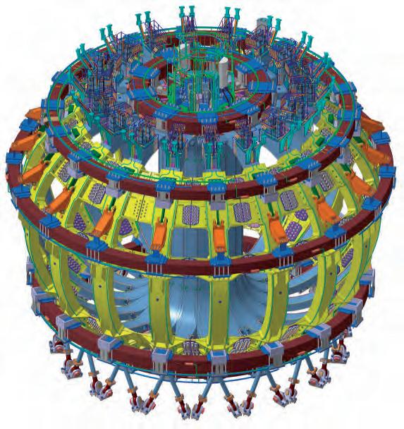
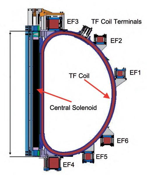
Fig. 3. Arrangement of the magnetic cage formed by TF, CS, and EF coils. ∼ 7.43 m
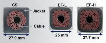
Fig. 4. Cross section of the CS and EF conductors. The TF windings consist of six double pancakes each wound from six turns with a total conductor length of 1,360m. The conductor allows a nominal current of 25.7kA to achieve a magnetic induction of 2.25T on axis. To stay superconducting at about 4K a helium flow of about 4g/s is passing the conductor. As the pressure drop along the whole conductor length of the TF coil would be excessive, the helium coolant passes the double pancakes in parallel. Electrically, the pancakes are connected in series through joints with a very low resistance of a few nano-Ohm. Cooling of all TF coils is achieved by a cryogenic circulator in a closed loop at a pressure of 0.5MPa with a total mass flow rate of about 1kg/s. As the electromagnetic forces by the magnetic fields are tremendous, each TF winding is enclosed in a massive steel casing. The different casings are wedged together along the straight inner section to support centralising forces. Keys in the upper and lower inboard curved regions support overturning moments on the coils during plasma operation. Finally, an outer intercoil structure between the vessel ports, consisting of bolted shear plates with friction and insulated surfaces contacting the TF coil case fixes the toroidal arrangement of coils. The TF coils are resting on the Cryostat base through gravity supports, which block rotation but allow radial shrinkage of the magnets during cooldown. Dedicated cooling pipes on the surface of the structures reduce the heat load to the coils.
The four independent modules of the CS can be powered independently. All structural and operational loads are reacted internally. The CS is supported from the bottom of the TF coil casing. The EF coils are clamped to the TF coil case. They are self-supporting with respect to radial (in-plane) loads. Eddy currents play a vital role in tokamaks. They are induced by the varying magnetic fields and the plasma currents and may disturb the magnetic field around the plasma, heat the structures of the superconductive magnets, and add pressure on larger metallic surfaces such as the thermal shields. Therefore, electric insulators are separating adjacent TF coils, the segments of the Vacuum Vessel and of the Thermal Shields.
MAGNET SHARED COMPONENTS
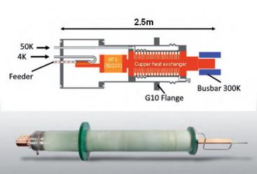
These components provide the interface between the magnets and their services – cooling, power supplies and instrumentation – and are often of a common design for all the magnet systems. They comprise: • current feeder lines and their structural support • cryogenic supply lines (cryolines) including cryostat feedthroughs, servicing the conductors, magnet structure or feeders • current leads connecting coil conductor and feeder lines – for JT-60SA made from high temperature superconductor to minimise cooling requirements • coil terminal boxes (housing the current leads) • valve boxes for distribution and control of the helium flow • quench relief valve assemblies • instrumentation, cabling and control cubicles The toroidal field coils use three separate power supplies, each feeding six coils in series, whereas the four central solenoid coil modules and the six equilibrium field coils have one power supply each. All the coils use high temperature (∼50K) superconductor (HTS) current leads to connect to the power supplies. To connect the three groups of TF coils, the four CS modules, and the six EF coils with the power supplies, twenty-six HTS current leads (CL) are installed in five coil terminal boxes and connected to the coil terminals by superconducting feeders. The design principle of the HTS CL together with a photo of a real current lead is shown in Figure 5. The current from the bus bars at ambient temperature is entering the current lead through a clamped contact and passing along a high-conductive copper heat exchanger, thereby bridging the temperature range down to –213°C (60K). The conductive heat along the copper and the ohmic heat produced by the current is absorbed by a small flow of helium entering at a temperature of –223°C (50K). In order to further reduce the conductive heat to the cryogenic components, a high temperature superconductor (HTS) section Fig. 5. HTS CL Schematic.
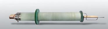
with zero resistance for the current but low thermal conductivity is soldered to the lower end of the heat exchanger. The cold contact of the current lead has a resistance of only a few nano-Ohms and feeds the current through a superconducting feeder to the coil terminal. During a fast discharge of the magnets, the current leads may reach high voltages of a few kilo-Volts. Therefore, the current leads are mounted at the Coil Terminal Boxes through insulating epoxy (G10) flanges (see Figure 5). The electric connections between the coils and the current leads in the satellite boxes are using the same conductor as for the coils. The routing of these feeders had to consider thermal shrinkage and avoid electromagnetic stray fields, which could disturb the magnetic cage. Although the superconducting coils feature almost not voltage drop, they may reach high voltage of several kV during an emergency shutdown. Therefore, all helium lines are electrically isolated by electric breaks.
If a superconductor quenches (this is, becomes normal conducting by, for example, an excessive current or heat load), its resistance immediately increases, leading to a dangerous situation, unless the current from the power supply is immediately reduced to zero. In order to supervise the superconducting circuits, pairs of voltage taps are installed at all coils, feeders and the HTS sections of the current leads. Special amplifiers continuously check if excessive voltages caused by a quench appear.
CRYOSTAT
The main purpose of the cryostat is to provide a vacuum of about 10-4 Pa around the cold magnet components to block thermal conduction and minimise the thermal loads.
The body of the cryostat is a cylindrical structure about 14m in diameter and 15.5m high (see Figure 6). The cryostat vessel is made of 30mm single-walled stainless steel. The skin has a structure to support the weight of all the ports and port plugs and to withstand the vacuum pressure.
Fig. 6. Cryostat during trial assembly at works.
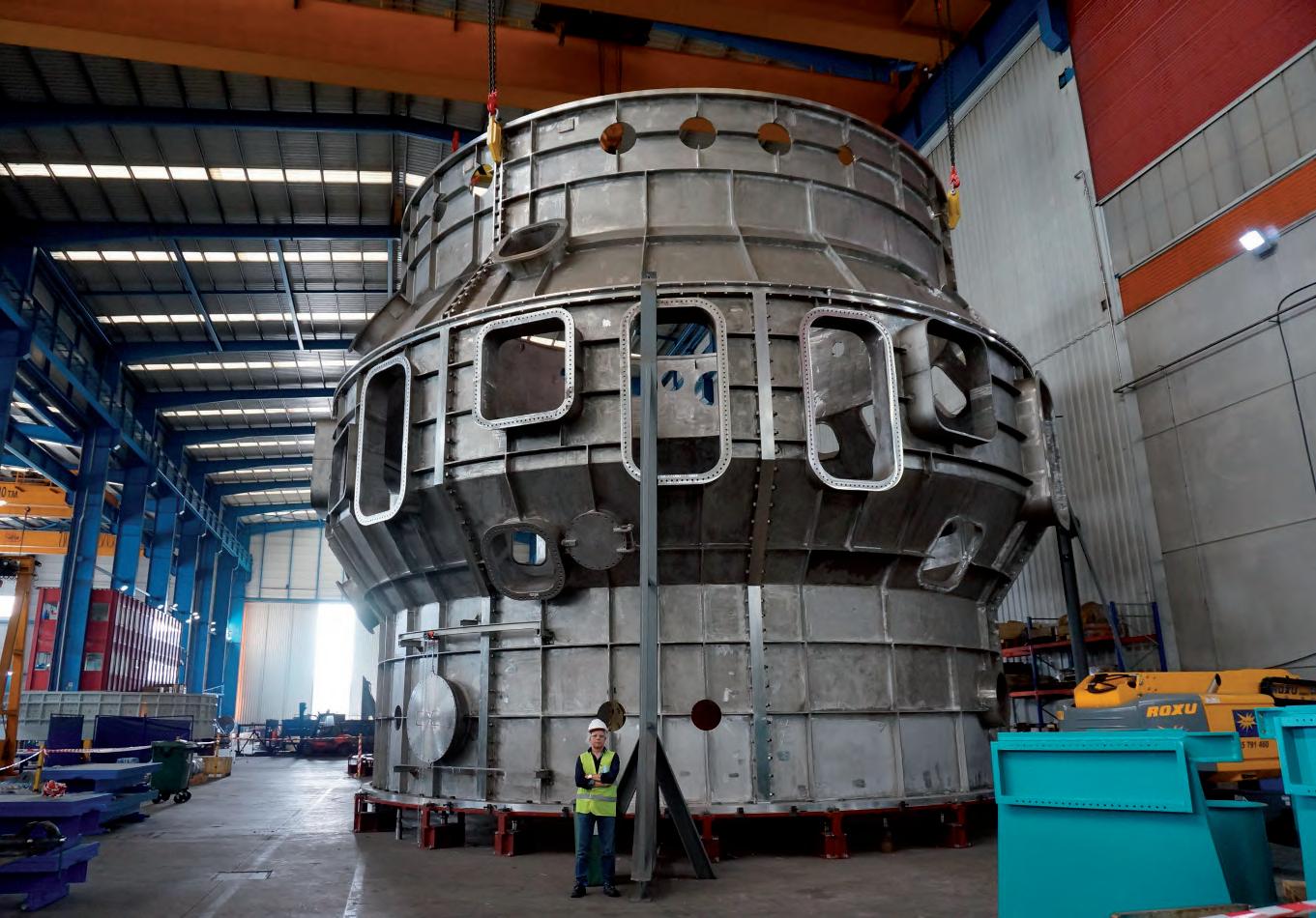
The top lid is shifted upwards to maximise the inner space for the assembly and maintenance of cryogenic devices and connections. It allows access for possible direct removal or reinstallation of the central solenoid and features a rupture disk to take care of any overpressure exceeding 0.02MPa. Large numbers of ducts interconnect the VV ports with the corresponding penetrations in the cryostat vessel and provide access for maintenance and inspection equipment, pumping, exhaust, in-cryostat feeders, etc. The cryostat base is designed as a robust structure to support the dead weight of superconducting magnets, thermal shield, and the vacuum vessel, including in-vessel components, as well as operational electromagnetic loads, thermal stress during baking, and standard operational conditions, accidental overpressure, and seismic loads.
THERMAL PROTECTION (VACUUM, THERMAL SHIELD, CRYOSTAT)
The magnet coils need to be thermally protected against heat radiation from the Vacuum Vessel, the Ports and the Cryostat. This insulation is achieved by high vacuum and thermal shields enclosing completely all cold components. The thermal shield consists of eighteen segments electrically insulated from each other to prevent excessive electromagnetic forces during disruptions. The cryostat thermal shield (CTS) is a single-walled with multilayer superinsulation. The vacuum vessel (VVTS) and port (PTS) thermal shields consist of two panels reinforced by edge frames and gaseous (80K) He cooling pipes, fitting snugly in the gap between TF coil and vessel. Due to the narrow space no additional MLI could be applied between the VVTS and the VV. The thermal shield is supported by the TF coils, between EF coils 5 and 6, and at the top on alternate TF coil casings. All thermal shields are cooled by a forced flow of pressurized helium gas at about 90K. Although the thermal shield must block all thermal radiation, it must nevertheless have gaps to allow for evacuation and maintaining a high vacuum.
PLASMA VESSEL AND PORTS FOR ACCESS TO THE PLASMA
Enclosing the hot plasma requires a donut-shaped vacuum vessel with several openings for diagnostic instrumentation, heating and cooling systems and plasma fuelling. The vessel is double-walled with a gap of about 150mm of boronized water. This water allows maintaining an operation temperature of 50°C during cooldown and nominal operation. The dissolved boron salt absorbs fast neutrons from D-D plasma reactions protecting the surrounding magnets from getting activated and heated. In order to clean the walls of the vessel the temperature of the Vacuum Vessel needs to be baked occasionally at 200°C by draining the water and circulating hot nitrogen. Due to the reduced neutron shielding capability of the nitrogen gas, the plasma is not operated during vessel baking. Access to the plasma is realized by seventy-four ports of different size with cross sections ranging between 0.15m² and 1.2m². The largest ports are used for Neutral Beam Injection and have a rectangular cross section of 1.8m times 0.7m. In order to compensate the differential contraction between the Vacuum Vessel and the Cryostat, each port is equipped with a bellow. In addition, insulators in the ports separate the ground potential between the Vacuum Vessel and the Cryostat to avoid electric interference. Every toroidal 40 degrees, a gravity support with spring plates is installed at the bottom of the vessel. These gravity supports withstand the operational electromagnetic forces and absorb the thermal expansion during the baking operation. The vacuum vessel system also includes the high vacuum pumping and the plasma fuelling subsystems as indicated in Figure 7.
Fig. 7. The Vacuum Vessel, its ports and evacuation system.
IN VESSEL COMPONENTS
The major in-vessel components (see Fig. 8 for guidance) are: • the divertor cassettes • the inboard first wall • the stabilizing baffle plate and outboard first wall • the fast plasma position control coils • the sector coils for resistive wall mode (RWM) control • the magnetic diagnostic coils • the error correction coils • the cryo-pumps for hydrogen and helium pumping
For the first phase of operation only a lower divertor has been installed, optimised to allow ITER-shape and high-triangularity plasmas. A fully equipped upper divertor is planned at the start of the extended research phase. During that phase too, once operation is better understood, a mono-block type carbon fibre composite (CFC) divertor armour is planned for the outboard side able to withstand a heat load
of ∼15MW/m2. During the initial research phases, due to the smaller expected heat load, a flat tile type divertor armour will be used instead. The use of metallic divertor tiles is also being considered for the later research phases. Cryopanels are installed behind the divertor to improve pumping capability for hydrogen and helium. A helium cooled chevron baffle at 90K together with a water-cooled chevron in front of the pumping hole reduce the heat load on the cryopanels by thermal and microwave stray radiation. Two in-vessel coils are used for fast plasma position control. Independent power supplies are connected to each coil block to control vertical and horizontal field at the same time.
The primary function of the stabilizing baffle plates is to enhance the ideal beta limit and to improve plasma positional stability. They have been designed as a double-wall structure and are covered with a bolted carbon-armoured first wall.
Sector coils for the RWM control will be installed around the openings of the stabilizing baffle plate facing the plasma to minimize the control response time. Since each sector coil has its own current leads, the magnetic field mode of m/n=3/1 or 3/2 can be controlled depending on the configuration of the power supply connections. Saddle coils (rectangular loops on the vacuum vessel) are included to manage slow or non-rotating MHD modes arising from any slight field misalignments after coil assembly. Three coils are located poloidaly at six toroidal locations.
POWER SUPPLIES FOR SUPERCONDUCTING COILS
The power supply system consists of the power supplies for the superconducting and control coils, the beam and EC heating and current drive systems, and power supplies for auxiliary plant (see Figure 9). Existing equipment has been re-used where possible, on a rearranged AC supply network. New power supply systems have been designed and manufactured to feed the superconducting TF and PF coils. Typical operation of the TF coil power supply
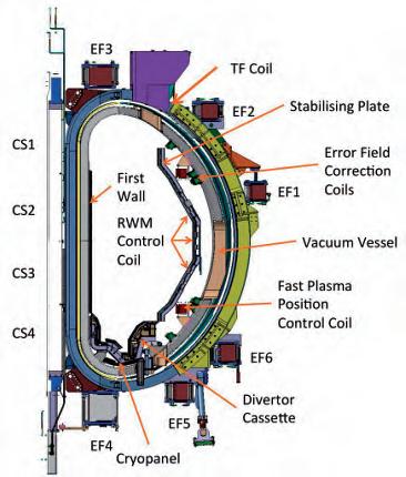
Fig. 8. Arrangement of the in-vessel-components.
Fig. 9. Schematic of the Power supplies for the different coils.
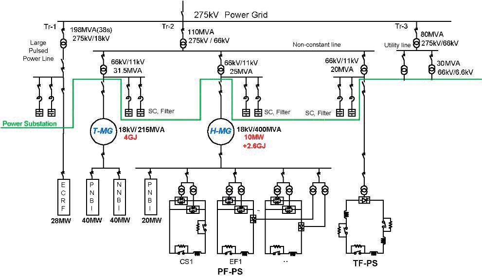
is that the TF coils are energized every day in the morning, before the start of the plasma experiments, and demagnetized at the end of the day after the experimental period. The PF coil power supply circuit components are a ‘Base PS’, a ‘Booster PS’, and a ‘Switching Network Unit (SNU)’. In case a superconducting coil quenches or a power supply fails, a quench protection circuit (QPC) is connected in series with the TF and PF coils to allow fast extraction of the coil energy. The quench-protection circuit consists of a DC current interrupter, discharge resistor, and pyro-breaker for back-up protection.
CRYOGENIC COOLING AND DISTRIBUTION
In order to reach the superconducting state of the magnet coils, they have to be cooled close to absolute zero, i.e. to about 4 K. For this purpose, a powerful refrigeration system was set-up. This refrigeration system supplies cold helium at about –269°C (= 4 K) to the coils, and at –183°C (= 90K) to the thermal shield. The High Temperature Superconductive Current Leads (HTS CL)
require a flow of helium at –223°C (= 50K). During plasma operation, the hydrogen fuel and the helium exhaust need to be evacuated by cryo-pumps with a high pumping capacity. These cryo-pumps are supplied with very cold helium at –269.5°C (=3.7K).
The magnets and their structures, together with the thermal shield, represent a total cold mass of 734t, requiring a total refrigerator capacity corresponding to an equivalent heat load of about 9kW at 4.5K. Producing such a capacity requires an electric power of 2.4MW and an amount of about 1,300l/h of liquid nitrogen. The refrigeration requirements are not constant during operation: During cooldown, a large amount of refrigeration is needed at gliding temperatures. Without magnet operation at nominal operation temperatures, the average refrigeration demand of the coils and structures is around 2kW only. However, during plasma initiation, eddy currents in the cold structure, AC losses in the superconductor, and neutron loads by D-D reactions accumulate to a peak load of about 60kW for about 15 seconds. Managing such high load variations requires a sophisticated plant concept with intermediate buffering of heat in a liquid helium reservoir.
The cryogenic system as shown in the process scheme in Figure 10 comprises the following main subsystems:
• A system of eight parallel warm screw compressors with sound protection, a common oil and water removal system, pressure control and a gas management system. • A refrigerator cold box (RCB) with cryogenic heat exchangers, liquid nitrogen precooling, integrated 80K purifier, and three cryogenic expansion turbines provide the necessary refrigeration at different temperature levels. • An auxiliary cold box (ACB) including a 7,000l liquid helium buffer a subcooler for pre-cooling the cryopump refrigerant, a cold compressor to subcool the liquid helium and two cryogenic pumps to circulate approximately 2kg/s of supercritical helium through the coils and their structures.
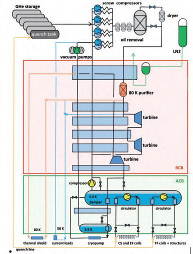
Fig. 10. Schematic of the Cryogenic System and its interfaces to the cooling loops in the Tokamak.
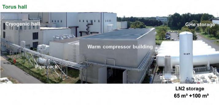
Fig. 11. General arrangement of the cryo-plant. • Instrumentation and a local control system allow autonomous operation of the refrigerator as well as remote control by the central JT-60SA control system. • A gas storage comprising six warm helium storage vessels with a total volume of 1,500m³, a liquid nitrogen storage, cryogenic transfer lines, and warm interconnecting pipework. One of the storage vessels is modified with a dedicated inlet nozzle to recover cold helium gas after a quench or a fast discharge of the superconducting coils The arrangement of the Cryogenic System at the site of QST is shown in Figure 11. For the compressor station, a new building was erected on the west side of the JT-60SA experimental building. The cryogenic hall neighbouring the torus hall accommodates the RCB, ACB and the subcooler vacuum pumps. A large, 60m long and 1m diameter cryogenic transfer line connects the cryolines from the ACB to the cryostat, the valve boxes and the coil terminal boxes. The cooling towers, the gas storage vessels and the liquid nitrogen storage are located next to the compressor hall as shown in Figure 11.
PLASMA HEATING
JT-60SA shall finally use up to 34 MW of neutral beam (NB) heating and up to 7 MW of electron cyclotron resonance (ECR) heating systems. The upgraded NBI system for JT-60SA (see Figure 12) consists of twelve positiveion-based NBI (P-NBI) units and one negative-ion-based NBI (N-NBI) unit. The P-NBI units control deposition profile and plasma rotation. The P-NBI system has been modified from that of JT-60U in order to extend the pulse duration from 10 s to 100 s keeping the same injection power. High power N-NBI is also required to provide sufficient NB current drive capability for high-beta steady-state (full non-inductively driven) plasma development.
Fig. 12. Neutral Beam Injection and ECR heating systems.
High power N-NBI also contributes to heating of the central region in high-density plasmas with a dominant electron-heating fraction, which is relevant to ITER and DEMO plasmas heated by alpha particles. The beam line of the co-tangential N-NBI unit is offset downward from the equatorial plane by ∼0.6m to drive off-axis plasma current, and hence to produce reversed shear with a high bootstrap current fraction. The ECRF system (shown in Figure 12) generates or sustains high performance plasmas, provides assistance to plasma start-up and cleaning of the first wall of the vacuum vessel.
During integrated commissioning phase, the system is composed of two gyrotrons, two transmission lines and one launcher injecting two RF beams. One of two gyrotrons is a newly developed multi-frequency gyrotron, which oscillates at 110GHz and 138GHz with 1MW for 100s for long-pulse heating by 2nd harmonics EC resonance that is much longer than the 5s required in JT-60U. In addition, the gyrotron has a capability of 82GHz at 1MW/1s operation, which enables efficient plasma start-up and wall cleaning by a fundamental EC resonance. The other 110GHz, 1MW gyrotron used on JT-60U runs with the multi-frequency gyrotron up to 5s.
DIAGNOSTICS
Some limited diagnostics will be prepared for Integrated Commissioning for machine protection and confirmation of the controllability of plasma:
CO2 Laser interferometer The tangential CO2 laser interferometer is used for measurement of line-integrated electron density along a tangential chord. The measured line-integrated density will be used not only for plasma physics, but also for real-time feedback of plasma control.
Visible spectroscopy
The purpose of this system is to measure the intensities of Ha emission, Bremsstrahlung emission and other spectral lines. The viewing chord is tangential between two opposite horizontal ports. Two identical optical systems, each of which consists of a vacuum window with an effective diameter of 43mm, a lens with a focal length of 100mm, and a bundle of nineteen optical fibres with a numerical aperture of 0.2, are installed in the two ports. An image of the central optical fiber is mapped onto the vacuum window of the other optics system at a distance of 13.7m with a diameter of less than 40mm. The layout of the optics allows to calibrate the sensitivity of the whole spectroscopic system including the vacuum window without in-vessel work: a standard light source just outside the vacuum window can be used to calibrate the sensitivity of the other optical system through the two vacuum windows. In addition, simultaneous measurement from the two ports enables to improve the accuracy through comparison and provide redundancy.
Soft X-ray detector arrays
The purpose of this system is to observe the last closed flux surface (LCFS), the magnetic axis and the electron temperature profile by measuring the intensities of soft X-ray emission through a pinhole. For Integrated Commissioning, only soft X-ray detector arrays are available for the electron temperature profile measurement. The system consists of two detectors. Each detector has an Absolute X-ray and UV (AXUV) sensor, a pre-amplifier and thin beryllium films. The detectors are put on the end of a port plug and the port plug is inserted at a horizontal port. Both detectors have a similar measuring range set at a poloidal angle of about 15 degrees downwards which allows to measure the lower half of the plasma. The outputs of the pre-amplifiers are transferred to digitizers installed inside the electromagnetic shield box located in the underground floor. Since Be films work as band pass filters, the electron temperature can be evaluated by the ratio of the intensities from two detectors with different film thickness.
Visible TV cameras (+ two light guide)
The main role of the visible TV diagnostic is to monitor the plasma wall interactions at the divertor, limiter and first wall, which are mostly covered by carbon tiles. The field-of-view (FoV) for each viewing chord is in the order of 80°C. A light-guide systems will be installed under each port-plug for illuminating the vacuum vessel without plasma emission, using a fiber optics connected to the metal halide lamp (375W). A ‘periscope’ system is used in the sections, in which the visible TV camera (analog color CCD) is located at the end of the port-plug having double window without shutter and cooling. On the other hand, an ‘endoscope’ system is used for another section, in which the visible TV camera is located inside the magnetic and neutron shielding box that is located outside the cryostat, using a set of mirrors with pin-hole and relay/collection optics.
Event Detection Intelligent Camera (EDICAM)
This diagnostic has a tangential view into the torus. Equipped with wide-angle optics, the FoV is in the order of 80°, thus the camera view can cover about 1/5 of the plasma vessel. A fast wide-angle visible video diagnostic system, based on the Event Detection Intelligent Camera (EDICAM) can also measure, in addition to recycling and impurity influx, the visible light emission associated with fast phenomena such as plasma start up, disruptions, gas injection or even edge filaments.
Langmuir probes
The primary purpose of the Langmuir probes is the detection of the divertor leg during its sweeping. The position of the divertor leg evaluated from the Langmuir probes is compared with that evaluated by the Plasma Control System (PCS) or equilibrium solver (Meudas). This comparison shall confirm the controllability of the plasma position and shape. To evaluate the position of the divertor leg, four Langmuir probe heads (two is the inner divertor region
and two the outer divertor region) are installed at three toroidal sections of the upper divertor. Additional three heads are installed around the outer divertor region to evaluate the position of the divertor leg for various plasma configurations. The Langmuir probe head is composed of a corrector, insulators, a connector and bolts. A mineral insulated (MI) cable is connected to the collector with the connector. A DC voltage is supplied by a power supply installed in the tokamak hall and passed by the MI cables through vacuum feedthroughs of the horizontal ports. An ion saturation current (Iis) for detection of the divertor leg position is measured at a time resolution of ≤ 50 ms with the data acquisition system installed on the tokamak hall. Evaluation of electron temperatures (Te), electron densities (ne) and floating potential (Vf) can be evaluated by sweeping the applied voltage.
ASSEMBLY
Before assembly of the JT-60SA tokamak could begin, the JT-60U tokamak and much of its peripherals were removed and temporarily stored in other controlled areas for re-use or to allow the decay of radioactive afterheat. Assembly of JT-60SA began at the start of 2013 with the installation of the cryostat base followed by the lower poloidal field coils (EF4, 5, 6) one year later. This was followed by the vacuum vessel assembly, except for one 20° segment. The toroidal field coils (TF) and their thermal shields were moved into position through this gap, and the vessel then closed and lower port sections added. The upper EF coils (EF1, 2, 3) and CS were then moved into place and the remaining port sections attached. During this phase, some of the in-vessel components were installed in parallel. Auxiliary systems such as diagnostics, NBI and ECRF were respectively refurbished and assembled into place around the tokamak. Power supplies and the cryoplant were installed and connected in parallel with the assembly activity in the torus hall.
Fig. 13. Superconducting transition of all 18 TF coils.
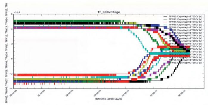
INTEGRATED COMMISSIONING
Integrated Commissioning started in spring 2020. During this period, all subsystems and their interplay were checked and brought successively into operation. After an extensive leak test, the thermal shields and the magnets were cooled to operational temperature. On 26th November 2020 all coils passed the transition temperature and became superconducting (Figure 13). During cooldown and operation, continuous mass spectroscopic measurements confirmed the perfect leak tightness of all circuits. Analysis of the temperatures and mass flow rates indicated that the heat load on the thermal shield and the magnets was well within the expected load range. In a next step the Vacuum Vessel was heated to 200°C for about two weeks to enhance outgassing of water and other impurities. Despite the increased thermal load on the cold components the magnets could be maintained at 4K. In January 2021, the power supplies were successively connected to the coils. While all TF coils are connected and operated in series, the CS modules and EF
coils were tested individually. Step by step the currents through the coils were ramped up to several kA. On 2nd March 2021 all eighteen TF coils reached the nominal current of 25.7kA. During a plateau of about 40 minutes the first ECRH driven discharge was achieved (Figure 14). During subsequent tests with the other EF coils an unexpected arc developed between two coil terminals resulting in a leak in a helium pipe and forcing the stop of operation. The origin of this arc is being investigated and measures to improve the electric insulation are under way.
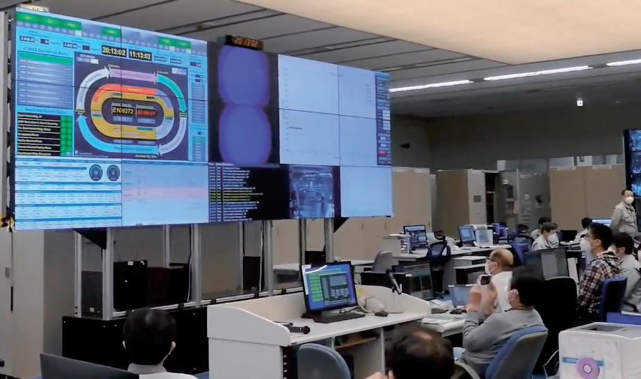
Fig. 14. First ECRH driven discharge at full TF magnetic field of 2.25T.


