12 minute read
Guillaume Vitupier


THE ITER CRYOSTAT
Guillaume Vitupier (ITER Organization)
Advertisement
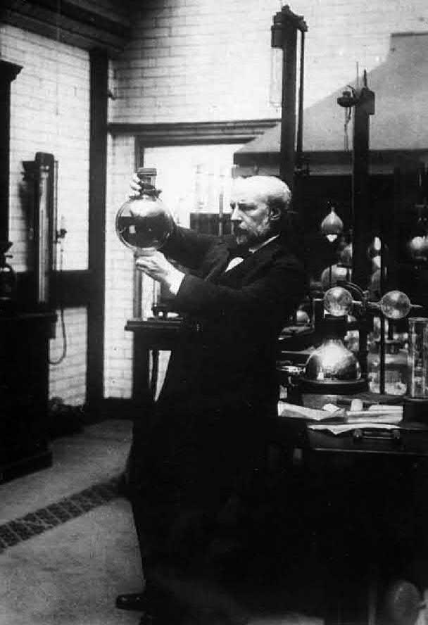
James Dewar
Dewar flask (or thermos bottle)
Long neck (and lid, not shown) to hinder heat convection
Inner bottle
Outer bottle
Nothing (vacuum) Vacuum to prevent thermal conduction
Both inner and outer bottfers are silvered to reflect radiation Seal-off point (melted closed from vacuum connection)
Fig. 1. Cryostat Conceptual Design – The Dewar Flask. INTRODUCTION
Cryostats are devices whose main function is to maintain a cool environment for the systems housed inside (from cryo meaning cold and stat meaning stable). Cryostats are usually assembled into a vessel-type construction whose conceptual design can be compared to that of a vacuum or Dewar flask as shown in Figure 1. Although conceptually similar, naturally the ITER Cryostat is a somewhat larger and more complex than a simple Dewar flask! Here are a few challenging features that the ITER Cryostat needed to address: • Provide the largest high-vacuum pressure chamber ever built (16,000m³) to maintain high-vacuum, ultra-cool environment for the ITER Tokamak components. • Act as primary support for the heaviest Fusion Tokamak machine ever built and transfer about 20,000t of weight to the civil infrastructure.
• Provide over 220 access points for maintenance and operating systems (diagnostics, cooling, heating, magnet feeding etc.).
The following paragraphs present the different development stages of the ITER Cryostat from the design justification through to the manufacture and inspection, sub-assembly, and then final assembly/construction. At this stage, all main sections of the cryostat have been fully designed, manufactured and sub-assembled. The ITER Cryostat is now being assembled in its final location in the Tokamak Pit.
DESIGN
Cryostat Function
The cryostat is one of the major components of the ITER machine, which is a nuclear facility (INB-174) built to research fusion power. The cryostat is a large, stainless steel structure surrounding the vacuum vessel and superconducting
magnets. The main functions of the cryostat are to provide a vacuum environment and to support the main components of the basic Tokomak. The cryostat is one of the world’s largest vacuum systems. A vacuum environment is vital, particularly for the ITER Magnet systems. These are superconducting magnets which are cooled down using supercritical helium in the range of 4 Kelvin (–269°C). In order to maintain that low temperature, it is essential to minimise the heat transfer between the magnets and any surrounding components as much as possible. A vacuum is therefore needed to perform this heat transfer reduction function, together with the Thermal Shield systems. The ITER cryostat eventually provides the high-vacuum, ultra-cool environment for the ITER vacuum vessel and superconducting magnets.
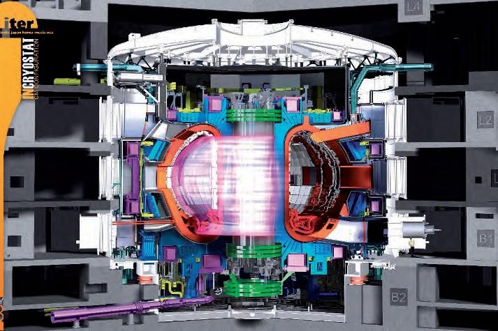
Fig. 2. ITER Cryostat (in white) view with in its environment.
Fig. 3. ITER Cryostat composed of four sections. Design Description
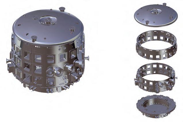
The cryostat is a fully-welded, single wall reinforced cylindrical chamber with an upper dome-shaped lid and a flat bottom, as shown in Figure 3. Its overall dimensions of 28m in diameter and 29m height with a shell thickness varying from 50mm to 200 mm. The main cylinder is 50mm thick and reinforced internally with both horizontal and vertical stiffeners. The diameter of the outer cylindrical part is reduced to 19m below the divertor ports. These two cylinders of different diameters are connected to a pedestal ring and horizontal plate. The pedestal ring is the platform that supports all the weight of the magnets and vessel systems. The cryostat system is made from 304/304L dual grade stainless steel. The main requirements for dual grade marking are low carbon content as for grade 304L for improved weldability and minimum tensile properties, as for grade 304.The cryostat is composed of four main sections: Base Section, Lower Cylinder, Upper Cylinder and Top Lid as shown in Figure 3.
Top Lid
Upper Cylinder
Lower Cylinder
Base Section
The cryostat has three main supporting features. The first, providing vertical support, is a set of 18 sliding bearings (CSB: Cryostat Spherical Bearings) installed on the underside of the pedestal ring and interfacing with the concrete crown wall on the pit floor. The second is the Vertical Skirt Support (VSS) connecting the main cylinder wall to a stage of the bio-shield at B2/B1 level and providing vertical upward support. The VSS allows radial movement of the cryostat shell in case of any helium and water spillage inside the cryostat. The toroidal support for the cryostat is provided by the third feature, the Toroidal Skirt Support (TSS). The TSS are installed on the outer edge of the cryostat and are locked toroidally against the bio-shield to prevent horizontal movement of the Cryostat during seismic events. The Cryostat has access points for all the systems required to operate and maintain the Tokamak. The connections of the cryostat at these points with the surrounding systems (mainly the vacuum vessel and the building) is ensured through rectangular or circular sections bellows, which compensate for the relative movements of the vacuum vessel, cryostat and building interfaces during normal operation and accident protocols.
Design Justification The ITER cryostat is subjected to different types of loads: pressure, inert, electromagnetic, and thermal. Specification of cryostat loads starts with the definition of the simple load cases. Load combinations are then defined with respect to the ITER Global Load Specifications. Each load combination is categorised (Cat. I to Cat. IV) based on probability of occurrence, ranging from normal operation to extremely unlikely. Based on the above loading conditions, the cryostat system design is justified using Structural Integrity Assessments performed as per ASME VIII Div. 2 Ed. 2010 design by analysis rules. These assessments are conducted through finite element analyses using ANSYS software. These analyses aim at verifying all code-specified failure modes: plastic collapse, local failure, collapse from buckling, collapse from cyclic loading (fatigue).
Fig. 4. Non-linear buckling analysis for the cryostat.
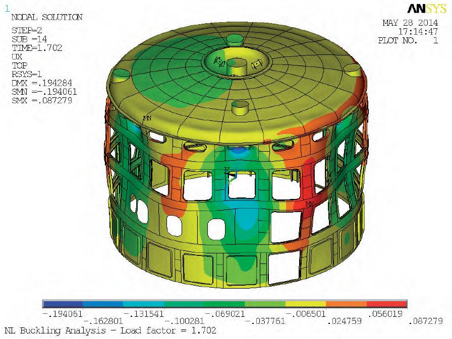
Figure 4 illustrates these analyses, showing the structural assessment of the cryostat cylinder under cooling water system interface loads. These loads are induced by dead weight, thermal expansion and seismic accelerations, and are applied at the top of the upper cylinder. Plastic collapse and the collapse from buckling failure modes are analysed using a load combination of dead weight with vacuum and seismic action simultaneously through linear static, linear buckling and non-linear buckling analyses (including imperfections). For technical reasons linked to the Finite Element Model size and thus the associated calculation run time, a component needs to be broken up into several zones of calculation. A global analysis of the component is then completed to determine which connections and loads or displacements to be applied to each zone boundary.
This global/local analysis scheme is applied to the structural assessment of the cryostat: • Global analyses are performed in order to obtain loading data at Cryostat sub-component boundaries or at Cryostat interfaces with other major systems but also to identify the most critical zones to be further assessed in detail • Local analyses are performed using the global analysis results as input data. The goal of these local calculations is to perform full sub-component assessments down to a level of detail of welding points or bolt connections for example. Global analyses at Tokamak level are also used for the cryostat assessments. A typical example is the global seismic analysis for the main Tokamak components which is then used to extract the cryostat seismic input data in the form of static equivalent accelerations or floor response spectra.
Fabrication in France
Top Lid Sector
Upper Cylinder - Tier 2
Upper Cylinder - Tier 1
Lower Cylinder - Tier 2
Lower Cylinder - Tier 1
Base Section - Tier 2
Base Section - Tier 1
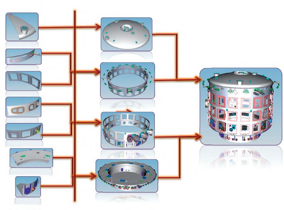
(i) Factory manufacturing of segments
(ii) Sub-assembly of sections at the ITER site temporary workshop (iii) Assembly in the tokamak pit
Top Lid Fabrication & Installation in France
Upper
Lower
Base Cryostat
Fig. 5. ITER Cryostat Manufacturing and Assembly Scheme.
MANUFACTURE, INSPECTION AND ASSEMBLY
The cryostat main sections/components are manufactured and assembled in three stages: (i)factory fabrication of segments/sectors of the main sections, (ii)sub-assembly of sections on-site at the ITER temporary workshop and (iii)assembly in the tokamak pit (Figure 5). The segments are manufactured in India, and Sub-assembly is completed in a dedicated temporary workshop on the IO Site while final assembly is performed directly in the tokamak Pit. The main challenge in the manufacturing of the cryostat is to a deliver a dimensionally compliant product considering how huge the system is and the heavy welding activities to be performed. For example, the tolerance band of the cryostat outer shell is only 100mm over a 30m diameter (less than 0.5% tolerance). Numerous prototypes and welding mock-ups have been made prior to commencing manufacturing of the cryostat in order to validate the manufacturing sequence, welding processes, dimensions control within tolerances, feasibility of weld non-destructive testing and jigs and fixtures requirements.
Factory segment manufacturing
The factory manufacturing produces segments/sectors of the main cryostat sections. Generally, each of the four main cryostat sections (base section, lower cylinder, upper cylinder and top lid) is divided in two vertical halves (Tier-1 and Tier-2) which in turn are divided into 60 degree sectors. For each section, the number of segments is therefore usually 12. The main reason for this subdivision scheme is to allow the feasible and safe shipping of these segments from the factory in India to the sub-assembly workshop on the IO Site in France; it would not be possible to ship larger segments. The largest and heaviest of these segment is from base section Tier-2, with a weight of about 120t and dimensions are roughly 14.5m × 6.5m × 1.7m. The raw materials for the cryostat mainly consist of plate and welding type products sourced from French and Indian steel manufacturers. It is essential for the raw product to be of the highest quality and all this material is 100% volu-
Fig. 6. 60 Degree Cryostat Base Section Tier-2 Segment.
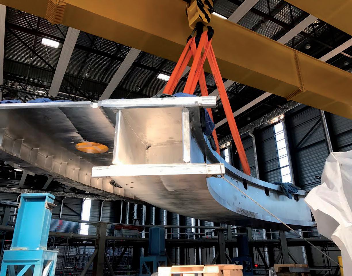
Fig. 7. Fitting of all ×6 Cryostat Base Section Tier-2 segments together in sub-assembly workshop on IO Site.
metrically tested for any defects. Low impurity requirements are also checked in order to minimise potential radioactivity that could occur during the nuclear operating phases of the Tokamak machine as much as possible. The manufacturing of the cryostat segments involves complex welding processes where distortions are controlled with the utmost care using optimised methods and sequences. Volumetric Non-Destructive Testing and Helium Leak Testing is performed following the welding. Dimensional compliance is checked at each stage using optical metrology (laser tracker).
Workshop section sub-assembly
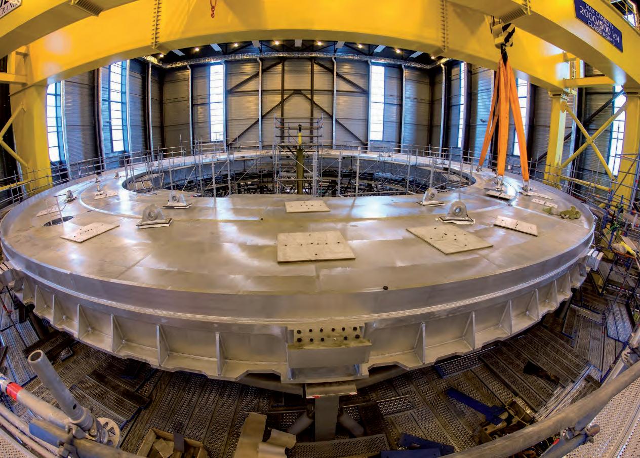
The cryostat segments shipped over from India are delivered to a dedicated workshop on the IO Site for sub-assembly. This mainly consists of fitting and welding cryostat segments together to form each of the main cryostat sections: base section, lower cylinder, upper cylinder and top lid. The cryostat sub-assembly workshop on IO Site is located near the Assembly Hall to ease transportation of the cryostat main sections from the workshop to the Pit. The workshop is 110m in length, 50m in width and 27m in height. It is capable of housing two 30×30 m assembly platforms; two cryostat main sections out of a total of four can therefore be sub-assembled in parallel. The workshop is equipped with a 200t capacity gantry crane which is used to lift, handle and fit the cryostat segments together for sub-assembly. For each of the four main cryostat sections, a transportation and fabrication frame is erected at the designated location. All segments are set up and tack welded together on the fabrication frame. Alignment and clamping tools are then used to achieve the fit-up requirements. The segments are welded in a pre-determined sequence, optimised to avoid distortions. This includes advanced welding techniques and processes such as automatic narrow-gap TIG welding of the plate up to 200mm in thickness. Volumetric Non-Destructive Testing and Helium Leak Testing are performed at each stage of welding and a dimensional inspection is performed using optical metrology.
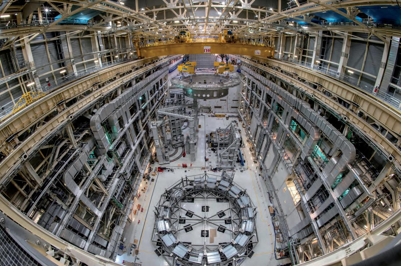
Fig. 8. Lifting Cryostat Base Section from the Assembly Hall to the Tokamak Pit.
Three out of the four cryostat sections have been fully sub-assembled: Base section, Lower Cylinder and Upper Cylinder. Top Lid sub-assembly is currently on-going with a completion date targeted for beginning of 2022.
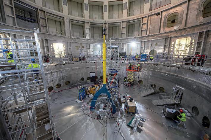
In-Pit assembly
Once their sub-assembly is completed, the main cryostat sections are prepared for In-Pit assembly. The first task is to transport them from the cryostat sub-assembly workshop to the assembly hall. It was initially planned to use a rail transporter, this is now actually done using SPMTs (Self Propelled Modular Transporter), which are platform vehicles with a large array of wheels. The SPMT is positioned under the manufacturing frame of the cryostat sections. In the Assembly Hall, the cryostat sections are then prepared for their last manoeuvre: gigantic lifting lugs and heavy duty accessories are rigged onto the components before the ‘big lift’ from the Assembly Hall up to the final destination in the Tokamak Pit. This lift is performed using the massive gantry cranes available in assembly hall which are used in tandem mode. The total capacity of these cranes is 2×750=1,500t. Moving at speed around 1 m/min and at a maximum altitude of about 25m, the components are transported form their layout area in Assembly Hall to the Tokamak Pit, 110m away. Once lifted and placed in the Pit, the cryostat sections are aligned using multiple jacking systems. Alignment precision is to the millimetre (less than 5mm) which is quite an accomplishment for such a heavy component, measuring 30m in diameter and weighing up to 1,250t (Cryostat Base Section). As with the segment manufacturing and section sub-assembly, a large part of the assembly work consists of welding. As before, welding distortion is optimising by carefully selecting sequences and processes in order to eventually meet the targeted positional requirements of the components in the Pit. The integrity of the welds is verified 100% using Ultrasonic Testing, which has been precisely calibrated and qualified to the exact configurations of these welds. The final component positions are checked using laser tracker metrology.
At the time of writing, two out of the four cryostat sections have been lifted to the Tokamak Pit: the Cryostat Base Section and the Cryostat Lower Cylinder. The welding of these two components, with a gigantic circumferential weld of about 90m length over a 50mm thickness, has been completed and all Non-Destructive Testing has been successful.
Fig. 9. Surveying component deformations using laser tracker during welding of Lower Cylinder onto Base Section in the Pit.