14 minute read
Fabio Villone


TOKAMAK BASICS AND MAGNETIC CONFINEMENT
Fabio Villone (Universitá di Napoli)
Advertisement
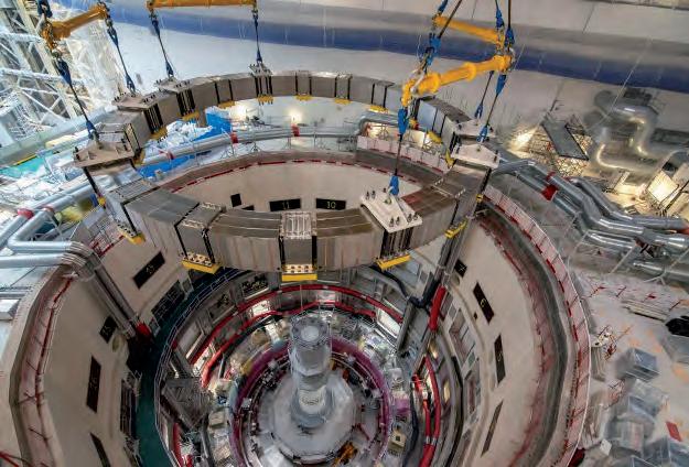
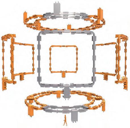
Fig. 1. ITER Central Solenoid (from ©ITER web site). PLASMA AS DEFORMABLE CONDUCTOR
Fusion plasmas are made of moving charged particles (electrons and nuclei), interacting with the magnetic field, as depicted previously. The number of particles involved in a typical plasma is enormous – in ITER, the expected density is approximately 1020 particles per m3, and the plasma volume will around 1,000 m3 – which makes it impossible to track the motion of each single particle. Instead, just like in ordinary gases, a macroscopic, fluid-like description can be conveniently used. This means that a plasma can be characterised by a pressure, a density and a temperature, possibly varying from point to point. The peculiarity of plasmas over standard neutral gases is the presence of charged particles, the motion of which depends on the knowledge of electromagnetic (EM) quantities; to study this situation, we need the so-called MHD (Magneto-Hydro-Dynamics) mathematical model, coupling fluid equations to Maxwell’s equations. The presence of electric charges in motion also allows an electric current to flow across the plasma – current is the quantity of net charge crossing a surface in the unit of time. Hence a plasma can be eventually described as a fluid-like, deformable conductor. In particular, as recalled previously, in Tokamaks (and ITER is no exception), the plasma has a toroidal geometry, so that it can be described as a toroidally-shaped deformable conductor. As such, a fusion plasma can be studied and treated with electrical engineering tools, although with some modifications and adaptations. Firstly, we can induce a net current in the plasma using the so-called transformer effect. In a standard transformer, two windings (primary and secondary) are magnetically coupled via a magnetic circuit, so that a time variation of the current in the primary winding induces an electromotive force and a current in the secondary winding. In a Tokamak, the primary winding is made of a dedicated set of coils, whose current flows in the toroidal direction and whose magnetic field belongs to the poloidal plane, i.e. is orthogonal to the toroidal direction; in ITER, it is the so-called Central Solenoid, CS, that serves this purpose (Figure 1). The secondary winding is instead the plasma itself: we can therefore say that a time variation of the current flowing in the Central Solenoid produces a
time-varying magnetic field linked with the plasma, which induces an electromotive force and a toroidally-directed current in the plasma via transformer effect. In some existing devices, like JET (Joint European Torus), currently operating in Culham, Oxford, UK, a magnetic circuit is also present, like in standard transformers, to improve magnetic coupling; ITER instead has no such structure and hence resembles a sort of ‘vacuum transformer’, in which the magnetic coil system is carefully designed and engineered in order to achieve good magnetic coupling between the Central Solenoid and the plasma, even without a magnetic circuit. The fact that a time variation of the current flowing in the Central Solenoid is needed to sustain the plasma current through a time variation of the magnetic field linked with the plasma (the so-called ‘flux consumption’) poses a technological limit to the achievable duration of the plasma discharge, which will be of the order of thousands of seconds in ITER. To overcome this limitation, external ‘current-drive’ systems are envisaged to have a significant non-inductive current flowing in the plasma, and internal mechanisms of current self-sustainment (‘bootstrap current’) are achieved by suitably tailoring the current density profile inside the plasma. In ITER, the overall current flowing in the toroidal direction thanks to all these mechanisms is nominally 15MA, i.e. one million times larger than the current flowing through a typical electric domestic appliance. It is well known that a current flow in a conductor produces heat thanks to the Joule effect, and plasmas are no exception in this respect. So, we can think of this mechanism (called ‘ohmic heating’) to heat the plasma and reach thermonuclear-relevant temperatures. However, a plasma has a peculiar feature: its resistivity decreases with increasing temperatures, exactly the opposite behaviour as usual metallic conductors. This means that, at high temperatures, it is increasingly difficult to further heat the plasma through ohmic heating. Eventually, an external source of energy is required to reach reactor-relevant temperatures. A first possible method for plasma heating consists of a system for injecting in the plasma energetic neutral particles (Neutral Beam Injector, NBI), which immediately ionise and provide net energy to the bulk of the
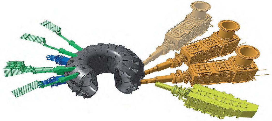
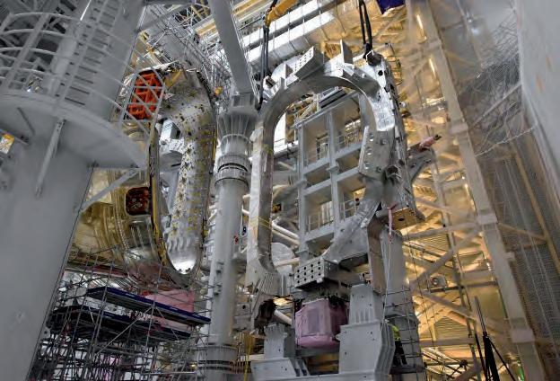
plasma. ITER in particular will have a NBI system with unprecedented characteristics, whose construction is an extremely challenging engineering endeavour per se (Figure 2). In addition, ITER will be equipped with a set of powerful antennas, which will be used to irradiate the plasma with an electromagnetic wave, which will be able to efficiently deliver its energy to the plasma if its frequency resonates with some characteristic physical phenomena occurring in the plasma, such as the electron or the ion cyclotron frequency – the frequency at which charged particles travel along a circumference with Larmor radius around magnetic field lines.
Fig. 2. ITER heating systems (from ©ITER web site).
EQUILIBRIUM, STABILITY AND CONTROL
When describing the plasma as a deformable current-carrying conductor, we can assume that its position and shape can be modelled using suitable magnetic fields. Indeed, the interaction between plasma current and magnetic field gives rise to the well-known Lorentz force, which is the basis of any electromechanical conversion system, such as electric motors and generators. As the plasma is deformable, this force determines its motion, position and shape, again ruled by MHD equations. In particular, it makes sense to determine the so-called equilibrium configuration for the plasma: a situation in which the global force acting on the plasma is zero, i.e. there is a perfect balance between the force of electromagnetic origin and the typical fluid forces, i.e. those related to the pressure gradients inside the plasma. In order to have an equilibrium configuration providing an effective confinement of the plasma, the magnetic field lines are forced to lay as spirals on nested closed surfaces, called ‘magnetic surfaces’, so that the charged particles do not hit the surrounding structures during their helical motion around the magnetic field force lines. The outermost magnetic surface, i.e. the magnetic surface outside which no confinement is possible, is called the ‘plasma boundary’, which also defines the plasma’s nominal shape. Outside the plasma boundary, the magnetic surfaces intersect the structures surrounding the plasma: any charged particle outside the boundary will hence hit the structures sooner or later, hence losing confinement (Figure 3). Each magnetic surface is characterised by a value of the ‘safety factor’ q, which intuitively can be defined as the number of toroidal turns per poloidal turn of any magnetic field line laying on such magnetic surface. The higher this number, the more is the magnetic field line ‘stretched’, in the toroidal direction. In Tokamaks, the safety factor is higher than 1, which means that the toroidal field is larger than the poloidal field – sometimes much larger. In ITER in particular, the nominal toroidal field is around 5T at the centre of the torus and above 10T in the inboard region, while the poloidal field is about 1T. In order to produce the required magnetic field to reach the equilibrium, a huge number of coils is needed: on one
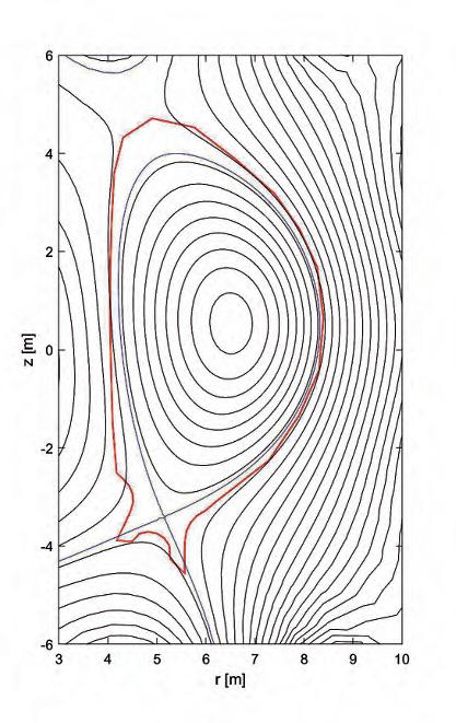
Fig. 3. Typical poloidal cross-section of the magnetic surfaces in ITER: plasma boundary (blue) and structures surrounding the plasma (red).
(a)
(c) (b)
(d)
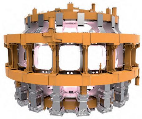
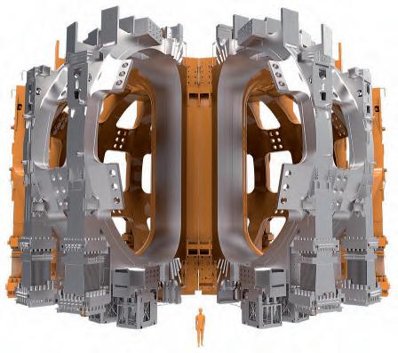
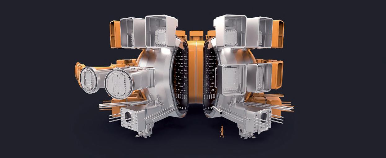
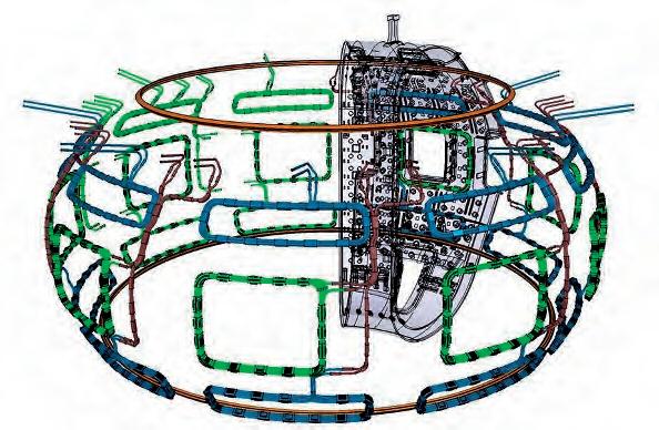
Fig. 4. ITER PF coils (a), (b) and TF coils (b), (c) (from ©ITER web site).
hand we have the Toroidal Field (TF) coils, producing the toroidal field, and on the other the Poloidal Field (PF) coils, which produce a magnetic field directed in the poloidal plane (Figure 4). Of course, also the current flowing in the plasma contributes to the overall magnetic field. The ITER coil system is described in detail by Alfredo Portone later on. Stability is an ubiquitous concept in physics and engineering. When considering a complex system like a fusion plasma, for which an equilibrium configuration has been identified as described above, we can intuitively define the stability of such equilibrium by looking at what the system does after an arbitrarily small perturbation of the equilibrium: if the system tends to move back to the original equilibrium configuration, we call it stable; if, instead, time evolution brings the system far from the original equilibrium, we call it unstable.
We can apply this intuitive definition to plasma deformations around a reference equilibrium configuration. Due to long-range EM interactions between particles, mathematically described by the MHD model mentioned above, there are situations in which macroscopic deformations of the plasma magnetic surfaces may become unstable, which means that, once triggered, their amplitude grows in time, potentially leading to the disruption of the whole plasma. These instabilities are usually classified in terms of their characteristics, both from the spatial and from the temporal points of view. Temporally, it is assumed that the perturbation exhibits a so-called ‘growth rate’, i.e. its amplitude grows exponentially in time as exp(γt). Spatially, it is important to characterise their behaviour as a function of the toroidal angle , which describes rotations around the vertical axis, and the poloidal angle φ, that can be introduced to define rotations on the poloidal plane. In particular, we identify the dominant Fourier spatial harmonics, i.e. the ‘toroidal and poloidal mode numbers m,n’, such that the perturbation can be approximated as a sinusoidal function of angles as sin(mθ +nφ). Clearly, the most dangerous instabilities are those showing a low mode number (hence being not spatially localised, but rather involving the bulk of the plasma
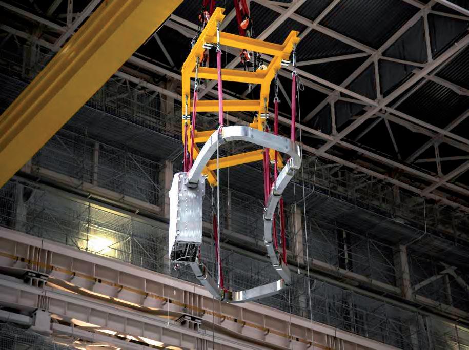
Fig. 5. ITER vacuum vessel: artistic view and component under construction (from ©ITER Organisation).
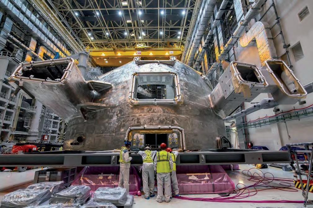
volume) and a high growth rate (hence developing very quickly in time). The ITER design is such that its nominal equilibrium configuration is prone to n = 0, i.e. axisymmetric instability, which develops as a unstable vertical movement of the whole plasma ring. This happens because the cross-section of the plasma boundary in any poloidal plane is not a circle but is rather a vertically elongated ellipse (Figure 3). Without any further action, this vertical instability would grow extremely fast, in a matter of microseconds. This is due to the fact that the overall plasma mass is very small, so that it reacts quickly to any external electromagnetic force acting on it. In fact, the plasma mass density is thousands or even millions of times smaller than the mass density of air; incidentally, this is the reason why it is absolutely necessary to create the plasma in a dedicated region of space where vacuum is made – the so-called ‘vacuum chamber’, delimited by the ‘vacuum vessel’ (Figure 5). In this situation, little can be done: the instability would be so fast that it is virtually impossible to counteract it. Fortunately, Maxwell’s equations provide some help in this respect: in fact, if the vacuum vessel is made of conducting materials, we can get a significant beneficial effect. The stabilising mechanism develops as follows. The instability makes the plasma move quickly in the vertical direction; as the plasma is a current-carrying deformable conductor, any movement will induce what are known as ‘eddy currents’ in the vessel – again, a transformer effect, in which the variation of magnetic flux linked with the vacuum vessel is now due to the plasma movement. The eddy currents induced in the vessel in turn produce an additional reaction magnetic field, whose ultimate effect is to oppose the cause generating the eddy current itself: this is the so-called Lenz rule, which is embedded in Maxwell’s equations and is at the basis also of the working principle of induction motors. Eddy currents therefore have an intrinsic stabilising effect: as long as such currents persist in the vacuum vessel, plasma instability is effectively counteracted. Unfortunately, eddy currents decay over time, due to the fact that the vacuum vessel is not a perfect conductor, but rather has a non-zero electric resistivity. Their stabilising effect therefore tends to vanish over the same time scale on which eddy currents decay.
Consequently, eventually the plasma motion is still unstable, but the growth rate of the instability is significantly slowed down, on time scales that in ITER are in the range of hundreds of milliseconds, i.e. something like five order of magnitudes slower than before. Thanks to this positive effect, one can now think of actively controlling the vertical instability, since it is taking place on a slower time scale, and external intervention is indeed possible. This is achieved thanks to a smart design of a suitable additional poloidal magnetic field provided by available coils. In ITER, it is planned to use not only a subset of the aforementioned PF coils, used also to provide the nominal equilibrium magnetic field, but also a pair of dedicated coils, located inside the vessel to be as close as possible to the plasma itself: the ‘Vertical Stabilisation (VS) coils’. The current required in these VS coils is determined in real time by a suitable automatic feedback controller, designed by resorting to sophisticated controller design techniques, which in turn need an accurate and careful modelling of the whole system comprising the plasma, the vacuum vessel and the coils, in order to quantitatively predict their electromagnetic interactions. In ITER it will be necessary to pay attention also to non-axisymmetric (n ≠ 0) modes, which can become unstable if the plasma pressure increases too much or if the safety factor drops too low. For this purpose, several dedicated non-axisymmetric coils will be installed. One set will be outside the vessel, consisting of 18 coils, arranged in six coils around the toroidal direction per three in the poloidal direction. Such coils will be fed with a DC current and will be used to correct the inevitable errors in the nominal magnetic field, due to misalignments, mounting tolerances, unwanted deformations and tilting of the PF and TF coils. These coils are therefore called Error Field Correction Coils (EFCC). Another set will be instead installed inside the vessel and will consist of 27 coils (9 in the toroidal direction per 3 in the poloidal direction). Their main purpose will be to control non-axisymmetric instabilities like Edge Localised Modes (ELMs) and Resistive Wall Modes (RWMs), that require a very precise tailoring of non-axisymmetric magnetic fields in the space occupied by the plasma (Figure 6).
(a)
Fig. 6. ITER Error Field Correction Coils system (a), one of the error field correction coils while being mounted (b) and in-vessel coils for control of MHD modes (c) (from ©ITER Organisation). (b)
(d)
With such a complicated arrangement of magnetic fields, it is necessary to carefully monitor the status of the machine, by measuring the magnetic field at key points of the device. This is achieved thanks to a huge number of magnetic sensors – in ITER, there will be thousands of such sensors – located all around the torus. The most common include: pick-up coils, capable of providing an estimate of magnetic field at given spatial points; the flux loop, measuring the magnetic flux linked with specific axisymmetric and non-axisymmetric paths; Rogowski coils, providing the net electric current flowing across a given surface. The development of such sensors is very challenging, not only because the stringent requirements in terms of accuracy, but also to the very harsh environment (e.g. neutron irradiation, plasma particle bombardment, high temperatures etc.) in which these sensors are required to deliver such high performance.
CONCLUSIONS
Unsurprisingly, like any other Tokamak, ITER is a highly complex machine from the electromagnetic point of view. Its working principle and correct behaviour depends critically on the precise definition and measurement of magnetic field across the whole device. Consequently, it will be equipped with an impressive number of magnetic coils, able to provide both the nominal magnetic field needed for plasma equilibrium sustainment, and the corrections determined in real time to counteract instabilities and control the plasma configuration. This is an incredibly challenging endeavour for electrical engineers, yet definitely attainable, thanks to the successful experience gained in many currently operating fusion devices.


