Force Sensor (Product No. 3143) Range: ±50 N Display resolution: 0.1 N
Data Harvest Group Ltd. 1 Eden Court, Leighton Buzzard, Beds, LU7 4FY Tel: 01525 373666 Fax: 01525 851638 e-mail: sales@data-harvest.co.uk www.data-harvest.co.uk
DS 038
Data Harvest. Freely photocopiable for use within the purchasers establishment
No 2
Force Sensor Contents Introduction ................................................................................................................................ 2 Connecting................................................................................................................................. 2 Measurement procedure ........................................................................................................... 3 1: Resultant force during oscillation of a mass ..................................................................... 3 2: Centripetal force (using a pendulum) ............................................................................... 4 3: Investigating Impulse ........................................................................................................ 4 4: Buoyant Force .................................................................................................................. 6 Practical information .................................................................................................................. 6 Subtracting an offset .................................................................................................................. 6 Background................................................................................................................................ 7 Technical information ................................................................................................................ 7 Investigations ............................................................................................................................. 8 Limited warranty ........................................................................................................................ 8
Introduction The Smart Q Force sensor uses a strain gauge, bonded to a metal beam, to measure bidirectional force (pull and push) perpendicular to the beam. The Force sensor is supplied with:
A thumbscrew for securing the Sensor to a stand
A spring – suitable for use with a 1.5 – 2.0 kg mass i.e. 2 kg mass hanging is ~ 20 N force
Fixings: a. A solid safety stop - for collision, reactive, impulse, or upthrust investigations b. A rubber cushioned stop - for collision or impulse investigations c. A hook - used to suspend a mass – for resultant, impulse, restoring, centripetal and upthrust investigations Securing thumbscrew Clamp stand hole Fixed end stop do not adjust Strain gauge
Offset knob (use to set output to zero)
Metal beam Clamping bolt do not adjust
Centre hole
With hook fitted
Connecting
Push one end of the sensor cable (supplied with the EasySense unit) into the hooded socket on the adaptor.
Connect the other end of the sensor cable to an input socket on the EasySense unit.
The EasySense unit will detect that the Force sensor is connected.
2
Force Sensor Measurement procedure
Avoid applying force sideways which could damage the beam
Damage can occur to the beam if impact is applied directly to the edge of the base
Apply force perpendicular to the beam Impact should be applied to the centre
If the investigation has angular motion
point at the base of the Force sensor
e.g. a pendulum, the Sensor must be allowed to swing with the mass to avoid a sideways force being applied to the metal beam.
The procedure for setting up a Force sensor will depend on the investigation it is being used for. Examples include: Thin bracket
1: Resultant force during oscillation of a mass
Screw the hook attachment into the centre hole at the base of the Force sensor.
If you have the Dynamics system, attach the Force sensor to the vertical pillar using a thin bracket. If this System is not available use the thumbscrew to clamp the Force sensor firmly to a horizontal support rod. Clamp the support rod in a boss attached to a retort stand. Keep the distance between the Sensor/ boss, boss/workbench, as close as possible to reduce flexing. Clamp the retort stand to the workbench.
Force sensor attached to the bracket using the thumbscrew Spring
Mass
Attach one end of the spring/ elastic/ string to the hook and add a mass. Note: The spring supplied is suitable to use with a mass of 1.5 - 2.0 kg.
Open the EasySense program and select Graph from the Home screen. Set to log for a suitable recording time e.g. FAST record with an intersample time of 20ms or less (depends on the period of oscillation).
Select Test Mode from the Tools menu. With the spring /elastic/string in equilibrium rotate the offset knob on the Smart Q housing to set zero (you may find it easier to make fine adjustments using a small screwdriver).
Pull the mass down and release to set it oscillating. Click on the Start icon to begin logging. The graph will display the resultant force acting on the mass.
3
Force Sensor 2: Centripetal force (using a pendulum) This investigation has angular motion so the Force sensor should not be clamped. Allow the Sensor to swing freely with the pendulum.
Remove the thumbscrew from the clamp stand hole. If the hole is rough (where the thread for the clamping screw has been drilled) smooth with some emery paper.
Screw the hook attachment into the centre hole at the base of the Force sensor.
Use rigid supports to reduce the effect of flexing.
Slide the Force sensor onto the support rod and fix an end stop (to prevent the Sensor falling off the end of the rod).
Check the pendulum can swing without fouling the bench or G clamp.
Attach one end of the pendulum to the hook. Add a mass e.g. 1 kg or more.
Open the EasySense program and select Graph from the Home screen. Set to log for a suitable recording time e.g. FAST record with an intersample time of 10 ms or less.
Select Test Mode from the Tools menu. With the pendulum in equilibrium rotate the offset knob on the Smart Q housing to set zero.
Displace pendulum sideways and release to set pendulum oscillating, click on the Start icon to begin logging. Note: The thumbscrew is absent End stop
Force sensor
G Clamp
Side view Front view: Sensor swinging with the pendulum
3: Investigating Impulse Very fast data capture is required to achieve satisfactory results for impulse investigations so they are only suitable for EasySense units capable of fast recording.
Screw either the cushioned or solid stop into the centre hole at the base of the Force sensor. Position the Force sensor securely e.g. at the base of a ramp so the dynamics cart will impact on the stop (centre point).
4
Force Sensor Light Gate attached to the track
Dynamics cart with interrupt card and crumple zone attached
Force sensor with an extension target attached
An extension target can be attached to the Force sensor to increase its frontal surface area. E.g. Cut a rectangle of 6 mm plywood (or equivalent), 11 x 4 cm in size and drill a 5 - 6 mm hole in the centre. Cut two more pieces of wood 4.6 x 4 cm in size and glue to the ends of the rectangle. Use the solid safety stop to attach the target to the centre hole in the base of the Force Sensor.
Two Force sensors can be used to measure the forces generated when a moving object collides with another object. E.g. Newton’s 3rd Law – Action and Reaction
5
Force Sensor 4: Buoyant Force Plastic bag
When measuring forces acting on a floating object use the solid safety stop provided.
Push down manually
Do not allow the Force sensor to get wet.
Beaker Force sensor
Bowl Blu Tack
Practical information
The Force sensor measures extension forces as positive.
You may find it easier to make fine adjustments to the offset knob on the sensor housing using a small screwdriver. If it proves difficult to set exactly to zero, see below for ‘subtracting an offset’ from a set of data.
Use the offset knob to set zero once the Force sensor is orientated in the correct position for the investigation.
Do not allow the Force sensor to get wet.
The clamp stand hole will accept a support rod of up to 12 mm in diameter. An Allen key or a mild steel rod bent into a right angle could be used to hold the Force sensor in position at the end of an air track.
Do not attempt to adjust the fixed end stop or clamping bolt (Allen nuts). The calibration for the Force sensor is set when the sensor is fully assembled. If any adjustments are made to the fixed end stops, measurements will no longer be valid.
Using 3.5 to 6.5 mm wide elastic works well. This type of elastic is used for driving model aircraft and as replacement rubber for fishing catapults. The elastic can be attached to the hook on the Force sensor by tying a loop in the end of the elastic.
The spring supplied is suitable for use with a mass of 1.5 – 2 kg. Pull the spring down gently (by only a few centimetres) before release so it oscillates freely and vertically. If the spring is pulled down too far you will get jerky movements and may exceed its elastic limit.
It is best to use a ‘crash box’ below a suspended mass in case the mass becomes detached during the investigation.
The SI unit of force is a Newton (N). One newton is the force needed to accelerate a mass of 1 kg by 1 m s-2.
Subtracting an offset A Pre or Post-log function can be used to subtract an offset from a sensor’s readings. Note: Use the Pre-log function for the tare to be applied to the data as logging progresses or the Postlog function to apply the tare to data that has already been recorded.
Rotate the offset knob on the Smart Q housing to set zero.
Find the tare value e.g. by using Test Mode from the Tools.
From the Tools menu select Pre or Post-log function.
Select Preset function, then General from the first drop-down list and Tare from the second, Next.
6
Force Sensor
Select the Force sensor, Next.
Fill in a name for the corrected data set. Enter the tare value. Make the value negative or positive as appropriate e.g. [2] – [2] = 0, [-2] – [-2] = 0. Finish.
Background When something is stressed its length changes. Change in length/original length = strain (e). The Smart Q Force sensor is a strain gauge comprised of 4 metal foil type resistors connected into a full Wheatstone bridge configuration bonded to a metal beam. A Foil type resistor – a pattern of resistive foil mounted on backing material. As the foil is subjected to stress, the resistance of the foil changes in a defined way.
Strain gauge
Metal beam
As force is applied to the beam it will flex. The vertical applied force is aligned through the centre of the beam. This force is transmitted to the beam via the clamp on the ‘free’ end of the beam. The free end will experience an anti-clockwise rotation curving this end of the beam upwards. The beam has two curves, in opposite directions as shown in the diagram below. Two of the resistors will be stretched (tension - T) and increase in resistance. The other two will be shortened (compression - C) and will decrease in resistance.
Resistor 1 and 2 are stretched (T)
Resistor 3 and 4 are shortened (C)
Strain gauge
Beam
Rotation causing a ‘S’ shape in the beam
FORCE
The change in resistance unbalances the Wheatstone bridge causing a very small output voltage, which changes linearly with the applied force. This voltage is amplified by an instrumentation amplifier (a high gain differential amplifier) and measured by the EasySense unit as force. If ambient temperature rises then since both strain gauges change in value by the same amount the bridge will remain balanced.
Technical information 4-element resistive strain gauge Wheatstone full bridge arrangement
7
Force Sensor Dual cantilever beam loading Temperature compensation via STC of gauge Maximum: 50 N
Investigations
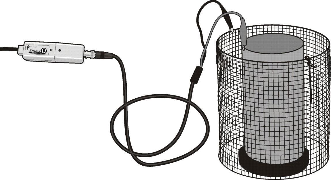
Changes in the circumference of a tree during a 24 hour period
Newton’s laws of motion
Frictional forces
Conservation of energy
Levers
Triangle of forces
Equilibrium
Resultant forces – static and dynamic
Bungee (impulse, momentum, conservation of energy and resultant forces)
Simple harmonic motion in a spring
Centripetal force in a pendulum
Collisions
Action and reaction
Buoyant force (flotation and resultant forces)
Limited warranty For information about the terms of the product warranty, see the Data Harvest website at: https://data-harvest.co.uk/warranty. Note: Data Harvest products are designed for educational use and are not intended for use in industrial, medical or commercial applications.
WEEE (Waste Electrical and Electronic Equipment) Legislation Data Harvest Group Ltd is fully compliant with WEEE legislation and is pleased to provide a disposal service for any of our products when their life expires. Simply return them to us clearly identified as ‘life expired’ and we will dispose of them for you.
8