HEAT PUMPS

EXPLANATIONS AND INSTALLATIONS
HPACMAG.COM


RESIDENTIAL WATER HEATER

Reduces water heating costs up to:
50, 66 & 80 USG Models available
Electronic Display for temperature setting, operating modes and diagnostics
Powerful 4,500W Back-up Heating Elements
208V and 240V installation options
Eligible for the Canada Greener Homes Grant
WATER HEATER FOR SMART BUSINESSES
Interactive Control: Touchscreen LCD display to select modes, view run information, get troubleshooting alerts, and more.
Quick Installation: Integrated design and pre-charged refrigeration system make for a quick and easy install.
Industry Leading 4.2 COP
High Performance: First-hour delivery exceeds 150 GPH and heat pump power rating of 3.15 HP.
Durable Design: Glass coated tank and electric elements that feature incoloy sheathing for protection from corrosion and scaling.


Here are some of the fundamentals of heat pump operations.
By Dave DemmaOur intrepid HVAC writer chronicles his own journey towards air source heat pump acceptance and installation.
By Ian McTeerA pair of nearly 20-year-old downtown 10-storey condo buildings replace their air-cooled chiller with air-to-water heat pumps to provide cooling and offset their gas-fired heating load.

 By Doug Picklyk
VRF
A retrofit project at the community arena in Bridgetown, Nova Scotia led to a cost-saving opportunity.
By Dan VastyanMontreal west-end health network undertakes $18.8 million energy efficiency retrofit program.
By Doug Picklyk


If you’re familiar with servicing AC units, the heat pump has just a couple more items that need to be addressed.
By Dave DemmaWhy heat pumps will expand the hydronics market in the years to come.

 By John Siegenthaler
HPAC Magazine receives unsolicited materials (including letters to the editor, press releases, promotional items and images) from time to time. HPAC Magazine, its affiliates and assignees may use, reproduce, publish, re-publish, distribute, store and archive such unsolicited submissions in whole or in part in any form or medium whatsoever, without compensation of any sort.
Doug Picklyk (416) 510-5218 DPicklyk@hpacmag.com
David Skene (416) 510-6884 DSkene@hpacmag.com
Amanda McCracken (647) 628-3610 amccracken@hpacmag.com
Kim Rossiter (416) 510-6794 KRossiter@hpacmag.com
Jaime Ratcliffe jratcliffe@annexbusinessmedia.com
Urszula Grzyb 416-510-5180 ugrzyb@annexbusinessmedia.com

Peter Leonard (416) 510-6847 PLeonard@hpacmag.com
Scott Jamieson
NOTICE: HPAC Magazine, Annex Business Media, their staff, officers, directors and shareholders (hence known as the “Publisher”) assume no liability, obligations, or responsibility for claims arising from advertised products. The Publisher also reserves the right to limit liability for editorial errors, omissions and oversights to a printed correction in a subsequent issue. HPAC Magazine’s editorial is written for management level mechanical industry personnel who have documented training in the mechanical fields in which they work. Manufacturers’ printed instructions, datasheets and notices always take precedence to published editorial statements.
Contents Copyright © 2023 by Annex Publishing & Printing Inc. may not be reprinted without permission.
We acknowledge the financial support of the Government of Canada through the Canada Periodical Fund (CPF) for our publishing activities.
Proud member of:
The invention of the heat pump has been credited to American inventor Robert C. Webber, and it was quite by accident that the concept for the heat pump was discovered. In the late 1940’s Webber was experimenting with his deep freeze and, get this, as legend goes he accidentally touched the “outlet pipes of the cooling system” (the discharge line) and burned his hand. You can almost see the light bulb going off in his mind
Webber decided to see if the mechanics could be reversed. Some minor modifications were in order for the ol’ deep freeze unit, as sources on the internet explain: “He connected the outlet piping from a freezer to a hot water heater and, since the freezer was producing a constant excess heat, he hooked up the heated water to a piping loop.” A small fan was used to transfer the heat from the hot water to the air, and voila the heat pump was born.
According to Lord Kelvin’s Second Law of Thermodynamics, heat will always travel from a warmer area to a colder area. Webber saw this as “pump -
ing” heat from a warmer area to a colder area, hence the “heat pump”.
After he saw that his invention was successful, he built a full-size heat pump to provide heat for his entire home. His design used copper tubing buried in the ground through which he ran refrigerant to gather the ground heat. The gas was condensed in his cellar, providing heat for the entire house.
Now, taking Webber’s initial idea and applying it to a typical air-conditioning unit—with the addition of a few modifications—you have the modern residential/commercial heat pump.
Utilizing Kelvin’s Second Law of Thermodynamics, the process of blowing warm air through a fin-tube coil, with a cold fluid (refrigerant) flowing through the tubing, will result in heat transferring from the air to the fluid. This lowers the temperature of the air in the conditioned space and the result is what we know as “cooling”.
The goal of the vapour compression cycle used in a refrigeration/air-conditioning system is to provide a continu -
ous source of cold liquid refrigerant to a fin-tube coil (evaporator), which will result in a continuing ability to transfer heat from the refrigerated space.
A basic review of the cycle:
1.Low pressure superheated refrigerant vapour, containing the heat from the refrigerated space, flows from the evaporator into the compressor.
2. The compressor “compresses” the vapour into a high-pressure vapour.


3. The compression process adds heat to the refrigerant vapour, resulting in a high temperature (superheated) high-pressure vapour leaving the compressor.
4. The superheated refrigerant vapour exits the compressor and flows into a fin-tube coil (condenser). Air flows through the condenser, transferring vapour’s heat content to the air.

5. The temperature of the superheated high-pressure vapour is reduced and experiences a phase change into a warm liquid.
6. The warm liquid flows to the expansion device and experiences a pres -
Here are some of the fundamentals of heat pump operations. BY DAVE DEMMA Figure 1: Four-way reversing valve. Figure 2: Reversing valve in the cooling mode.sure drop. This lowers its temperature to the saturation temperature corresponding to the lower liquid pressure. 7. This low pressure/low temperature saturated liquid flows through a fintube coil (evaporator) located in the refrigerated space. Air in the refrigerated space is transferred to the liquid refrigerant, causing a change of state into a vapour. All of the liquid should change state to a vapour prior to exiting the evaporator tubing, resulting in a cool vapour flowing to the compressor inlet.
Simply put, the cycle transfers heat from the refrigerated space to the refrigerant. In order for the vapour compression cycle to be an endlessly repeating cycle, the heat from the conditioned space has to be transferred away from the refrigerant. This occurs at the condenser, located in a space where the temperature is of no concern (outdoors). The refrigerant can then again start the cycle to allow it to be used to transfer heat from the refrigerated space, over and over.
A standard air conditioning system transfers heat from the conditioned (re -

frigerated) space, lowering the temperature in the space. That heat transferred to the refrigerant, plus the heat added to the refrigerant during the compression process, is transferred to the outdoor air via the condenser.
The heat pump also transfers heat from the conditioned space, but in a heat pump application the conditioned space is now outdoors. So, the evaporator is now located outdoors. The heat transferred to the refrigerant in that process, plus the heat added to the refrigerant during the compression process, is transferred to the air in the conditioned space via the condenser.
So, the heat pump is nothing more than the basic vapour compression cycle utilized in an air conditioning system, with added controls and valving to allow the system to either remove heat from the conditioned space (and transfer it to the outdoors), or remove heat from the outdoors (and transfer it to the conditioned space).
As such, rather than a distinct evaporator and condenser, we now have two dual purpose coils…an “indoor” coil and an “outdoor” coil.
Same vapour compression process, but the evaporator and condenser have changed places. We’re removing heat from outdoors and transferring it inside.
When the conditioned space requires cooling, the indoor coil functions as the evaporator, and the outdoor coil functions as the condenser, and when the conditioned space requires heating the refrigerant flow is reversed, allowing the discharge from the compressor to flow to the indoor coil, where it functions as the condenser. Reversing the refrigerant flow is accomplished with a four-way reversing valve (see Figure 1).
The reversing valve is located in the discharge line between the compressor outlet and the outdoor coil inlet. A solenoid coil (not shown), when energized, allows the reversing valve to “shift” from one position to another.
In the de-energized mode the refrigerant flows from the compressor discharge port to the inlet of the outdoor coil. The other two ports allow the refrigerant vapour from the indoor coil to flow to the compressor suction port (see Figure 2).
When the temperature in the conditioned space falls below the minimum heating temperature setting of the thermostat it will cause the following sequence of events to occur:
1.With the thermostat set in the heating mode the reversing valve will be energized.
2. The “Y” terminal on the thermostat will supply power to the compressor contactor, starting the compressor and outdoor fan.
3. The “G” terminal on the thermostat will supply power to the indoor coil blower motor, starting the motor. The unit is now in the heating mode, and the refrigerant flow through the reversing valve is shown in Figure 3.
There are several other modifications required in the refrigerant circuit to allow for the trouble free reverse flow required in a heat pump:
Liquid Filter-Drier: The filter-drier should be mounted in the common liquid line between the indoor coil and the outdoor coil. Given the nature of a heat pump, liquid refrigerant will flow from the outlet of the outdoor coil to the inlet of the indoor coil during the cooling mode, and from the outlet of the indoor coil to the inlet of the outdoor coil in the heating mode.
As such, a standard filter-drier cannot be used in this application. It will need to be a special filter-drier capable of removing system contaminants regardless of which direction the refrigerant is flowing—a bi-directional filter drier (see Figure 4).
Bi-directional flow is accomplished with a series of check valves at each end of the filter-drier housing. They allow re -

frigerant to enter from either fitting, directing it to flow from the outside of the core to the inside, and then exiting the shell through the opposite fitting.
Suction Filter-Drier: In the case of a highly contaminated system, where a suction filter-drier is needed to assist in the removal of contaminants, the only location for this would be between the outlet of the four-way reversing valve and the inlet of the compressor.
Given the limited space between these two components, a standard suction filter-drier is too large to be piped in. A special “pancake” style suction filterdrier must be used (see Figure 5, previous page). (note the Schrader access fittings on the inlet and outlet, as these are present to monitor the pressure drop through the filter-drier.)
Expansion Device: The indoor coil and outdoor coil both require an expansion valve. Since standard thermostatic expansion valves (TEV) are not suitable for reverse flow, they must be piped in parallel with a check valve.
This piping arrangement allows (1) liquid refrigerant to enter the TEV when a coil is used as an evaporator, and (2) condensed liquid to exit the coil (through the check valve) when a coil is used as a condenser.
There are also special “reverse flow” TEVs with internal check valves available. The internal check valve provides a reverse flow path (liquid entering the valve’s outlet, flowing around the TEV port via the check valve, then flowing into the common liquid line) when the coil is used as a condenser.
In package heat pumps, where there is a minimal distance between the indoor and outdoor coil, an electronic expansion valve (EEV) can be used in the common liquid line.
For years, when the term “heat pump” was mentioned it was understood to mean a conventional heat pump as de -
scribed above: that being a compressor, indoor and outdoor coils, and some form of expansion device for each coil, and a four-way reversing valve mounted between the compressor outlet and the inlet to the outdoor coil.
Over the years there have been advancements to heat pumps which have allowed them to operate more efficiently and over a broader range of temperatures in the winter. Aside from the air source options there are also “ground source” heat pumps (GSHP) that use either ground water or surface water as the outdoor coil’s heat transfer medium—a heat sink in the cooling mode or a heat source in the heating mode.
Ground source water a depth of 5- to 10-feet will remain at a fairly constant temperature year round. Likewise, water from subsurface aquifers and water from surface bodies will remain fairly constant in temperature (although at slightly greater depth would be required for surface bodies).
This is in contrast to the near 100F temperature difference that the outdoor ambient air temperature may experience between summer and winter conditions. This provides two benefits for heat pump operation:
• In the heating mode, the constant ground water temperature will provide a constant heat load for the outdoor coil, allowing sufficient load on the compressor to generate sufficient mass flow and heat of compression to provide a constant source of heat to the conditioned space.
• In the cooling mode the comparably low water temperature used as the heat transfer medium for the outdoor coil (condenser) will result in lower discharge pressures as compared to an air cooled condenser in the dead of summer. This results in greater compressor capacity and reduced electrical consumption, and can be illustrated by the higher SEER ratings available with GSHPs.
The various methods available for using the ground source water, can be categorized into either closed loop or open loop systems.
Closed Loop: This is an application where the outdoor coil is buried in the earth below the frost line, with the earth or ground water being used as the heat source/heat sink. In essence, the outdoor coil is fashioned into either a vertical or horizontal heat exchanger, and buried in the ground (see Fig. 6).
Horizontal heat exchangers require significantly more land area, but given the fact that they are not buried nearly as deep as vertical heat exchangers, they are less costly to install.
Vertical heat exchangers are normally used on larger buildings where it would be impractical to dedicate the necessary land required for burying a horizontal heat exchanger. These will be constructed of polyethylene and buried in holes drilled approximately 100- to 400-feet deep, and located approximately 20-feet apart. Each hole will have two vertical pipes connected at the bottom with a U-bend, forming a loop. Each vertical loop is connected via a manifold, and then connected to the heat pump.
Surface water heat exchangers can be used if the location has an adequately sized body of water. Depending on the Btu capacity of the heat pump there will be minimum requirements for volume and depth of the water body (in colder climates the water will need to be of sufficient depth such that the heat exchanger can be located well below the freeze line. Additionally, the water quality would need to meet some minimum specifications.
Open Loop: Imagine a system with a water cooled condenser being fed by an endless supply of 60F water. Because it’s an endless supply of supply water, there is no need for a cooling tower to transfer heat from the condenser water.
Or imagine a chiller receiving an end -
less supply of 60F water at its inlet. The water sees a 10F reduction in temperature in the chiller heat exchanger, but because of the endless supply of water there is no need for a fan coil unit to absorb heat to the chilled water.
That is the essence of an open loop system, an endless supply of water available as a heat sink for cooling or a heat load for winter applications. A pump supplies water to the heat exchanger in the heat pump. Since it is an endless supply, it is simply pumped through the heat ex-
changer, and then onto another location separate from the source of the water.
One drawback of this method is that there might be an issue with fouling of the heat exchanger due to the condition of the water. As fouling increases, it will then cause a reduction in the efficiency of the process.
In larger commercial applications hybrid systems might be employed where the presence of refrigeration equipment using water cooled condensers (and the accompanying water tower) would pro -
vide a year round supply of water for the heat pump’s heat load needs in the winter, and supply water for the heat sink needs in the summer.
The embrace of heat pump technologies around the world is growing. With the shift to decarbonization and electrification, it’s best to learn more about how these systems operate and can be applied for your clients. <>

Dave Demma holds a degree in refrigeration engineering and worked as a journeyman refrigeration technician before moving into the manufacturing sector where he regularly trains contractor and engineering groups. He can be reached at ddemma@uri.com.

(This article originally appeared in HPAC Magazine, October 2022)
Our
BY IAN McTEERIhave written extensively about heat pumps over the years—both air source and ground source. The ability of heat pumps to output several times more useful heating watts compared to wattage consumed has held my attention for decades. However, some units do it better than others.
I examined air source heat pumps used in residential applications going back to the late 1970’s. These early units were never meant for cold climates, having inadequate defrost controls, ridiculously high balance points, compressor protection was limited to nonexistent, and they were too often installed in combination with what I'd call second-rate air handling systems.
By the late 1980’s, demand defrost,
more robust compressors and increased awareness of appropriate air handling system design allowed air source heat pumps (ASHP) to improve their share of the residential market, especially in moderate climates as defined by AHRI Climate Region IV (2,000 to 2,500 heating load hours) down to Climate Region I with less than 1,000 heating load hours.
Most Canadian applications are best described by AHRI Climate Region V (greater than 3,000 heating load hours). ASHPs imported to Canada continue to be tested and rated for Climate Region IV. Thus, an ASHP with a Region IV Heating Season Performance Factor (HSPF) of 9.0 would have to be derated by 15% for Region V, the 9.0 HSPF unit becomes a 7.8 unit in most of Canada.
Even so, later model ASHP’s continued to be plagued by defrost problems that contribute to less efficient energy utilization by returning heat squeezed from frigid outdoor air back outside to defrost an iced-up outdoor coil. Additionally, during defrost, furnace heat would be utilized to temper air being delivered by a system now in cooling mode.
Properly installed and commissioned with a focus on shielding the outdoor unit from prevailing winds, defrost periods could be shortened dramatically, often to less than five minutes. Some control boards would allow several defrost periods of up to 15 minutes to accumulate before signaling a fault code that might not be intercepted until the next maintenance call.


Faulty defrosting, whether installation related or by mechanical fault, cause ASHP’s to gobble energy. Systems trying for defrost a third time after two consecutive 15 minute defrost periods should shut down, bring on backup heat, and signal the homeowner to call for service, at least so I say.
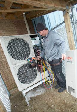
Figure 1 illustrates the extent of a frozen outdoor coil. Perhaps wind-driven snow overwhelmed the unit’s ability to defrost itself, maybe the defrost control board failed, or a coil sensor failed. Whatever the cause, it’s going to be a frosty no heat call for this hearty HVAC technician.

It’s worth noting that ground source heat pumps have no need to defrost themselves as the entire outdoor component is buried below the ground out of the way of raging winds, freezing rain, and knee-deep snowfalls.
Despite my reservations about plopping a refrigeration coil outside in freezing cold weather with a potentially wonky defrosting system, I’m now on board with the latest technology used with cold climate air source heat pumps (ccASHP).
In my own situation, costs related to the equipment and installation of a ground source heat pump are still beyond my budget; had I been able to rent the ground component from a third party as once proposed by a large utility, I think I’d be doing ground source today. But when it came time to move into a smaller house, we decided to avoid the condominium route and settled instead to purchase a mobile (or manufactured) house and have it installed on a concrete pad. I’m now located in a spacious senior’s mobile park in eastern Ontario not too far from Quebec.
So why would I choose a ccASHP when I’m aware of potentially suffering from one or more of their long-standing shortcomings? Just like anything else, major technological improvements, such as more robust inverter-driven compressors utilizing dense vapour injection, combined with microelectronic controls better managing
defrost cycles, give me the confidence that a properly installed, expertly commissioned and well maintained ccASHP will give me the comfort and efficiency I’m looking for.
This time I’m the homeowner, and I’m the one in the driver’s seat, right? After all, I have the gold, therefore I make the rules.
That might be the way some homeowners perceive relationships with various contractors ought to be, after all, it wasn’t that many years ago when some homes had “tradesman’s entrances” usually around back so the folks inside
wouldn’t have to see the scruffy blue-collar workers whilst sipping their tea.
Times have changed so dramatically that yesterday’s notion of simply looking around for the best deal is not the prime driver of the buying decision. “What should I buy?” and “Who should do the work?” were the top-of-mind questions for me.
No one wants to pay any more than necessary; hence, getting a “proper deal” is more like it.
HVAC equipment sophistication combined with the technical expertise needed to design, install, commission, and maintain one’s long-term investment in efficient HVAC products means homeowners need to do some homework.
For the first time in my life, I’ve had to shop around for several contractors needed to service my manufactured house. Searching ads on the Internet and those posted in the local newspaper, I still took the time to gather references from my community. I’m happy to say that the local contractors I hired have performed as expected. But I’m still waiting for other work to be done as everyone is incredibly busy and some materials are scarce.
My focus on contractor reliability and professionalism means that I’m not necessarily brand focused. I know every brand has suffered from “issues,” some more than others, however, it’s how the problems were dealt with that counts. I selected the Mitsubishi H2i Hyperheat ccASHP combined with a matching indoor air handler installed counterflow with 8 kW of supplemental backup electric heat.
I had the luxury of selecting an HVAC contractor having decades of experience with both air source and ground source heat pumps, including the Mitsubishi products. ATEL Air headquartered in Williamsburg, Ont. serves my area of eastern Ontario. My relationship with ATEL Air began when the owner, Jimmie Thom, decided to take on the Trane gas furnace and air conditioner product line in the
early 2000’s. I became a technical asset for ATEL and provided installation and service training along with telephone support for ATEL technicians over the years.
Admittedly, homeowners looking for a quality HVAC experience must rely on their research and testimonials to make the buying decision. I had a much easier time of it this go around.
The “old” in this case was a single stage downflow high efficiency gas furnace provided by the home manufacturer, and it was in rather rough shape after the bumpy trip to Ontario from Nappanee, Indiana.


The installation involved a considerable amount of electrical wiring, both high voltage and control voltage. ATEL Air is also an electrical contractor well versed in tricky wiring jobs. The 200-amp panel, mounted upside down and completely encased in the stud wall with drywall all around, required some careful treatment (see Figure 2). Minor cuts into the drywall exposed a new route for the heavier wiring running to the air handler and outdoor unit.
The new indoor air handler fit neatly into its closet application (Figure 3). I’m not thrilled by the “free delivery” return air system (Figure 4) as designed by the mo -
bile house manufacturer, but there’s no option for return ducting in such close quarters and it seems to work well enough through the extra-large grilles fitted to the utility room doors, so I’ll put that objection aside, at least for now.

I could conceivably run a duct through the utility area and pick-up some return air near the ceiling in the dining room area if necessary. Let’s wait and see if I do that!
My brand new Ecobee smart thermostat delivered my September Energy Report; already. The system operated in cooling mode just 15 hours; turns out my average setting of 23.5C saved me 16% in operating costs had I chosen a lower cooling set point of 22C.
Now for the best part, I’m in the bottom 50% of energy users compared to other Ecobee thermostat users. Obviously, I’m too sexy for my heat pump.
With the current concern about carbon pollution and climate change, governments continue to look for ways to reduce CO2 emissions, meaning natural gas, propane, fuel oil and wood-burning heating appliances have fallen into disfavour
“I'm happy to say that the local contractors I hired have performed as expected.”
amongst the regulatory set. Yet, switching many more households over to electric heat pump systems must also coincide with significant improvements to the North American electrical grid, including massive new sources of power generation.
Mark Jacobsen, co-founder of a Stanford University civil engineering team known as The Solutions Project, thinks Canada can meet 58% of its power generation needs using wind turbines alone by 2030. As I write, the Independent Electricity System Operator of Ontario (IESO) is reporting the province-wide hourly load at 12,905 MW with nuclear plants providing 68% of the demand, wind at 15%. With only nine years to go, I doubt we’ll see renewables take the lead in power generation by 2030.
I asked Greg Millard, service manager with ATEL Air, if his customers (existing and new) are asking for quotes on ground source or air source heat pumps.
His reply: “Yes, especially in areas where oil or LP (liquid propane) are the only alternatives.” At the same time, he is not currently discouraging fossil fuels, “but we do educate the customer about the alternatives, especially when LP and oil are the other options.”
Millard tells me his customers still want
tried and true gas furnaces and air conditioners as they continue to be perceived as the most affordable option when it comes down to costs related to installation, operation and maintenance.
With current supply chain issues, the very near future could be of the greatest concern to residential HVAC contractors. There may well be plenty of work in hand, however, Jimmie Thom, president of ATEL Air told me, “We spend a lot of time verifying equipment is available and expected shipping dates for sold jobs.”
Thom is concerned that some gas fur-
naces are in short supply, or out of stock, going into the heating season, and major replacement parts such as heat exchangers have longer lead times, weeks instead of days as in the past.


Millard said they’ve been forced to do some “brand hopping when needed and using a wider range of suppliers for material—basically buy it when and where it is available.”
To date, my ccASHP has been performing brilliantly. I’m using the thermostat’s automatic mode in which the cooling setpoint at 23.5C allows for some cooling and dehumidification on sultry autumn days.
Heating setpoint at 21C allows the equipment to take the chill off early in the day as winter gets set to arrive any time now. Will modern cold climate and ground source heat pumps eventually rule the day? I think so. <>
Ian McTeer is an HVAC consultant with 35 years of experience in the industry. He was most recently a field rep for Trane Canada DSO. McTeer is a refrigeration mechanic and Class 1 Gas technician. He can be reached at imcteer@outlook.com.

(This article originally appeared in HPAC Magazine, December 2021)

Rely on Mitsubishi Electric for all your Heat Pump requirements. From heating and cooling in the most extreme Canadian climates to the utmost flexibility in HVAC design, we’ve been raising the bar for over 100 years.

THE MITSUBISHI ELECTRIC ADVANTAGES

• #1 in VRF and Mini-Split Technology in Canada
• Specialize in Commercial and Residential Heat Pump solutions for thermal comfort and domestic hot water applications


• Strong Canadian customer support team
• Dedicated and experienced sales network
• Over 35 years of doing business in Canada
Learn more at www.mitsubishielectric.ca
The downtown Toronto skyline is littered with cranes popping out of high-rise towers in various stages of completion. In the third quarter of 2022 Toronto had 230 active cranes, by far the most of any city in North America (almost as many as the next 13 cities combined).
Toronto has set a goal of achieving net zero by 2040, so incentives and building code requirements are in place to minimize the greenhouse gas emissions of new towers. Yet the city is faced with retrofitting a large inventory of existing building stock, a process that’s just beginning to be addressed.
Built in 2003, a 10-storey condo lo -
cated at 120 Lombard St. in the heart of the city, is a short walk from all the bigcity attractions: shopping, dining and entertainment. “I like it, and I can’t leave because everything else is getting so expensive,” says Karima Dharssi, P.Eng., a senior electrical engineer and a resident of the building since 2010.
Dharssi is a member of the condo board and has been instrumental in spearheading energy efficiency initiatives including LED lighting retrofits and more recently the installation of new airto-water heat pumps.
The penthouse mechanical room on the
building distributes the hydronic heating and cooling to in-suite fan coil units at 120 Lombard as well as its sister building, a separate structure at 115 Richmond St. which is connected by a shared underground parking garage.

“We had two (large atmospheric) boilers functioning as our heating system,” explains Dharssi. “A couple years ago we decided to replace one of them (with a more efficient boiler) with the intention that it would become the primary boiler and the other would only kick in during colder temperatures.”
For cooling, the buildings’ two-pipe system switched in the summer months to be fed by a 110-ton air-cooled chiller.
In the fall of 2021 the condo board, faced with replacing its nearly 20-yearold chiller, approved the purchase of airto-water heat pumps to provide the cooling requirements of the buildings while also offsetting some heating capacity away from the existing gas-fired boiler.

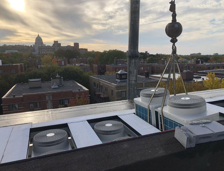
The condo committee selected Italianmanufactured air-to-water heat pumps from Climaveneta, a brand of Mitsubishi Electric. They represent the first field installation of this technology in Canada.

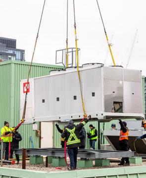
To meet the cooling capacity, two heat pump units were required, a 55-ton unit that fits in the space previously occupied by the chiller and an additional 65ton heat pump unit is being located on the rooftop.
According to Chris DesRoches, P. Eng., applied product manager – HVAC divi -
Canada, applications like this will become more common going forward. “Airto-water heat pumps make sense in this class of building as a retrofit product –it’s like a chiller-plus,” says DesRoches. “Instead of replacing a chiller like-forlike when it’s at end of life, we’re going to see more people upgrading to the heat pump and put it to work in the winter months, when you would normally be shutting down the chiller.”

After the condo board accepted the heat pump heating/cooling solution, the engineering design revealed necessary additional costs including upgrades to the electrical connections (a larger breaker to protect the system and a transformer to convert the voltage) along with new structural supports on the rooftop for the larger unit.
Fortunately, the unique aspects of this project appealed to a Toronto-based environmental agency who were able to
The Atmospheric Fund (TAF) is a nonprofit climate agency seeking scalable low-carbon solutions for broad implementation across the Greater Toronto and Hamilton Area (GTHA).


Keith Burrows, senior manager low carbon buildings at TAF, was contacted about the 120 Lombard project. “Our mandate is emissions reduction, and as part of that work we’ve been doing retrofits of multi-unit residential buildings for over a decade,” says Burrows. His team takes the lessons they’ve learned and offer retrofit services through what they call the Retrofit Accelerator.
Their services include funding support, project management, measurement and verification (m&v), and follow up. The services are offered for free to multi-unit residential building owners who are looking at retrofits targeting emissions reduction of 40% or more.
teria, and TAF partnered with the condo board, providing a financial contribution to keep the endeavour on track. The agency is also supplying project delivery support, resident engagement, and measurement and verification services.
“We are keen to see this technology implemented and determine how effective it can be,” says Burrows. TAF is partnering with the Toronto and Region Conservation Authority's Sustainable Technologies Evaluation Program (STEP) energy team who will perform the detailed monitoring.
“We’re confident the system will perform, but we’re going to verify this with hard data and we’re going to report on our findings as part of a case study,” says Burrows.
Part of the measurements include monitoring temperature and relative humidity in 22 suites across the two buildings. The team also conducted pre-retrofit surveys with residents to get a qualitative assessment of how they experience their indoor space and comfort, and they will follow-up with another survey in about a year to assess how the change is affecting the residents.
Before the heat pumps arrived the team at Prestige Mechanical, specialists in the Toronto high-rise residential market, was brought in to prepare for the installation.
“If it would have been a like-for-like install with a replacement chiller, it would have been simply cut the pipes and reconnect,” says Bradley Welch, estimator with Prestige. Instead, the team had to rework the entire mechanical room and create new piping loops and connections to suit the new heat pump system.

“The biggest challenge with this project was actually the logistics—it was a very small mechanical room in the penthouse,” says Welch. “A lot of thought and planning went into different ways to
support and mount equipment and piping while keeping floor space for walkways and paths for serviceability.”
First, the team demolished the old atmospheric boiler along with all the piping to and from the retired chiller. Each heat pump requires its own closed-loop circuit with a buffer tank, expansion tank and circulating pump. The heat pump loops are filled with a 40% glycol solution which runs outside to the heat pumps and ultimately supplies heating (or cooling) via brazed plate heat exchangers to a primary water-filled loop in the mechanical room, which isolates the glycol from the building distribution.
The primary circuit then transfers heat to the secondary distribution loop which supplies the heating/cooling water to the fan coils in the buildings.
The remaining gas-fired boiler in the mechanical room is on an injection loop that feeds the secondary circuit when it kicks in. If the heating boiler ever breaks
down, an additional heat exchanger between the domestic hot water (DHW) boiler and the heating distribution system is in place for emergency back up.
A new building automation system (BAS) controls the staging of the two heat pump units, and based on outside temperatures the BAS also controls when the boiler will kick in.
“Retrofits in older buildings like this can be really challenging,” says DesRoches. “What’s encouraging and unique about this project, is that the engineers are taking more of a qualitative approach, rather than quantitative. If we looked for hydronic heat pumps in the conventional sense, the numbers don't seem all that attractive compared with other technology choices for retrofits (like VRF), but they are a much more invasive retrofit. In this case they know the heat pumps will provide heat to the building, but at what point they’re going to be effective is subjective relative to the characteristics of the building itself.”
The initial target is to have the heat pumps supplying 45C (113F) water to the building down to -10C (14F), any colder and the boiler would kick in. Both DesRoches and Burrows acknowledge that getting the controls set perfectly for the system will be an iterative process.
“We’re confident the system will perform, but we’re going to verify this with hard data.”
TAF, together with the STEP team, will be involved with a real-time assessment of performance to ultimately help optimize the system.
“We want to learn from this project,” says Burrows. “How much gas can be offset? What can we do to improve the next installation of the same technology? And how can others benefit from the work that we’ve done?”
Initially the condo board was hoping to have the project complete in spring 2022, but due to supply chain issues and other delays preparations for the heat pumps were finished in the fall and the units arrived in mid-December.


DesRoches was on-site for crane day, an experience he describes as nerve wracking. “After the long lead times, the
last thing you want is to have something go wrong when these units are hanging, suspended, hundreds of feet up in the air.”
Ahead of crane day Prestige had to pre-fabricate the structural steel that was placed on the roof to support the larger 65-ton heat pump unit. That steel was the first to get hoisted up, positioned and bolted together. The next steps were to remove the outgoing chiller and then lift and set the heat pump units in place.
“We worked with Prestige closely leading up to the project, making sure vibration mounts were installed in the right location and the orientation of the unit was installed correctly,” says DesRoches. He was impressed with how smoothly the day went: “The team at Prestige had it down pat.”
The units were connected in the days after installation and commissioning of the system began in late January. “We’ve been involved with a lot of mini-split renovations and some VRF retrofits as well, but this is the first large central air-towater system that we’ve installed, which is part of the reason we’re really excited about it,” says Burrows, who adds that he’s already received calls from social housing providers and municipalities asking about the technology.
Electrification retrofits in buildings like this—with hydronics systems and fan coils—are challenging, and the ability to
provide a potential drop-in solution onto the roof to at least offset greenhouse gas emissions seems promising.
TAF projects a reduction in space heating emissions by 60% or more along with a reduction of over $200,000 in carbon taxes over 20 years.
“Once we do the case study on this project, we’ll have data and recommendations for improvements, and this will become a blueprint for broader decarbonization at scale for similar buildings,” says Burrows.
For Karima Dharssi and the other residents at both 120 Lombard and 115 Richmond, their pioneering efforts to switch to heat pumps places them well on their way towards net zero carbon living in the heart of Toronto, while also allowing them to benefit from lower costs in the long term.<>
(This article originally appeared in HPAC Magazine, February 2023)
“This will become a blueprint for broader decarbonization at scale for similar buildings.”Crane Day, the heat pumps were hoisted to the rooftop of 120 Lombard in Toronto in midDecember.
Communities of all sizes across Canada rally around their local hockey teams and arenas, and in October of 2001 the small town of Bridgetown, Nova Scotia located in the Annapolis Valley, was forced to close down its Bridgetown Arena after an assessment confirmed the community’s fears – the arena roof was deemed structurally unsound.

The arena needed repairs amounting to $400,000, and by the following year a $110,000 provincial Recreation Facility Development grant was issued and the community then rallied and raised the remaining funds to get the project going.
The work was finally completed and the facility reopened in March of 2003, allowing local hockey teams and other recreational skaters to return to their home ice.
Locals and guests skated through many years with very few changes at the re-opened arena. Then, in an effort
to reduce the facility’s energy consumption, the community sought an alternative to the electric resistance fan coils that had always been used to heat various areas in the building outside of the rink itself.
I skate at the arena, and we have an ad on the rink boards,” says Dale Comeau, founder and owner of Comeau Refrigeration in Bridgetown. The facility is near and dear to a lot of people and small businesses in this area. It’s home to the Bridgetown Hawks, and it serves a variety of athletic programs beyond hockey and as a local gathering place for children and adults of all ages.
Comeau Refrigeration was founded in 2008, and in time the company became a local Fujitsu dealer, after The Master Group, the region’s distributor, felt confident in Comeau’s ability as a seasoned refrigeration professional. He quickly realized the potential of the relationship and completed as much training as possible, while simultaneously marketing the product locally.
“We developed a reputation for installing mini-splits,” says Comeau. “A large part of that solution was, and is still, installing systems specifically designed for their resistance to ice accumulation on coils. This became a number one selling feature, along with efficiency and comfort. Our name came up in early conversations about improving the heating systems at Bridgetown Arena.”
According to Comeau, there were a number of issues that the Bridgetown Community Recreation Association
“Energy efficiency is now our priority. After that, it’s comfort, reliability and control.”
(BCRA) wanted to address at the arena, most of which Comeau was already very familiar with.
“Energy efficiency is now our priority,” says Steve Clayton, who’s been a BCRA board member since the 1970s, and chairman for the past 20 years.
“After that, it’s comfort, reliability and control. The original electric resistance units are expensive to run, loud, inconsistent, and each one needs to be turned on and off manually, which was a chore for those of us who take care of the arena.”
Before submitting a bid, Comeau compared the use of Fujitsu mini-splits with light commercial VRF systems.
Both would have accomplished the desired result, but using VRF systems dramatically reduced the number of outdoor units and offered simple centralized control. One other bid was collected for the project, but Comeau Refrigeration won the contract.

The 200- by 350-ft. arena features a single NHL regulation rink, kitchen, canteen, numerous changing rooms, restrooms, meeting rooms, a Zamboni room along with several common areas.
BCRA wanted to retrofit all of the spaces that were originally heated–meaning everything but the rink itself.
“We used a -10C design temp at the arena,” said Comeau. “Environment Canada and the Heating, Refrigeration and Air Conditioning Institute of Canada (HRAI) suggest -18C, but the existing resistance heat remains in place.
“I don’t think the resistance heat will ever be used, but it’s there [for backup]. Natural Resources Canada now gets involved with the engineering of systems like this and they help to procure grants, etc. They recommend system design to about 80% of the load, with electric resistance backup, allowing us to maximize heat pump efficiency.”
Comeau installed two, five-ton Airstage
J-II VRF units on the ground-level outside of the building, each fenced in to prevent any possible damage.
Inside in the building 14 zones are conditioned with wall-mount units ranging from 7,000 to 9,000 Btu/h, and a single low-static ducted unit in the Zamboni room providing up to 14,000 Btu/h.
“Even though it’s usually unoccupied, the Zamboni room must be kept warm,” explains Comeau. “Zambonis can cost six-figures, and they contain water, so keeping it well above freezing isn’t an op -
tion. That room also houses a lot of mechanical equipment for the rink, so there wasn’t much room on the walls for an indoor head. That’s why we used the ducted air handler.”
Installation of the heat pumps took several months as the team at Comeau Refrigeration worked around the arena’s busy schedule.
“The job was straightforward, though

VRF systems can require more time to install than mini-splits, at least in a building like this,” says Comeau. “The facility is steel framed and most of the partitions are cinderblock. To run line sets and wiring, we had to drill some walls and work around the steel structure. Obviously, the refrigerant headers are inside the building as well.”
Many of the indoor units are protected by custom-fabricated metal cages to safe-guard from misguided hockey sticks, airborne helmets, etc., and where line sets are exposed, Comeau installed wooden trim around them for greater protection.

The control panel for all of the units is centralized in an upstairs office. Most of the spaces are kept at 20C. Because the original electric resistance heaters were controlled manually, arena guests could turn up the heat to whatever pleased them. That’s no longer a concern.
“Everything about the new system is a major improvement,” says Clayton. “Temperatures are much more consistent, and not having to walk around the building twice a day to turn the heaters on and off is a big plus. Best of all – our energy bills are much lower.”
Because the electric bill reflects total facility consumption, Clayton can’t pin -
point exactly how much the heating costs have fallen. The rink’s mechanical equipment was upgraded at roughly the same time as the heat pumps, and LED lighting was installed as well.
“The retrofit was a huge part of the energy improvements here,” notes Clayton. “The savings are much needed, too. After all, the facility was built in 1976, so there’s plenty of upkeep. The retrofit avails funds for other projects. It was a fantastic change, and the systems work just as Comeau said they would.”
Looking forward, Clayton is hoping that some of the energy savings can be used to fund a large photovoltaic array installation on the arena roof.
“This was our first VRF project,” says Comeau. “It didn’t present any major challenges, and if it had, we knew that we could rely on Master Group for tech support. So we went into this project with a lot of confidence.”
Since completing the Bridgetown Arena project, Comeau Refrigeration has found the flexibility of VRF to be a great advantage on other projects.
“We’re getting some VRF traction in the residential market,” he says. “The housing market in Nova Scotia is ex-
tremely hot. People are buying properties way over asking price and making big investments and improvements. Some of these have been good fits for Airstage systems.”
According to Comeau, the biggest determining factor for use of VRF technology in residential applications is room count. With VRF, large houses with many zones can be served by a single outdoor unit, while it still makes sense to retrofit smaller homes with mini-split systems.
The federal government is promoting and offering grant programs for homeowners to move from fuel oil, which is still common in some areas of Atlantic Canada, to electric heat pumps.

“Canada is taking bold steps toward decarbonizing,” says Comeau. “Heat pumps are a great tool to achieve that goal, and VRF systems open up a lot of opportunities that weren’t available for heat pumps just a decade ago.” <>
Dan Vastyan is president of Common Ground, specializing in marketing communications with a focus on plumbing, mechanical and HVAC markets. danv@ seekgc.com
(This article originally appeared in HPAC Magazine, December 2022)
Come see us at booth #1427 at MCEE Expo in Montreal, April 19 & 20, 2023


You face enough challenges out in the field. Worrying about the performance of your equipment shouldn’t be one of them. At the end of the day, you need dependable technology that can deliver for your customers in any environment. Step up to Fujitsu General and get today’s most powerful lineup of mini-split and VRF solutions… along with ultimate peace of mind.

two day centres and several affiliated research facilities.
BY DOUG PICKLYKThe Integrated Health and Social Services University Network for West-Central Montreal (locally known as CIUSSS – Centre intégré univeritaire de santé et de services sociaux) covers an area that is home to approximately 371,500 people and provides services through more than 30 member facilities. Included is one of Canada's leading hospitals (the Jewish General Hospital) and an interlocking array of three specialized hospitals, five local community service centres, two rehab centers, six long-term care sites,

In August, 2019, the CIUSSS began working with Énergère, a Quebec-based energy efficiency consultancy and contractor, on a massive energy-savings project involving nine buildings which included changes to boiler rooms and entire mechanical systems to reduce the network’s environmental footprint and increase operational efficiency.
Over the past two-and-a-half years, more than 40 measures were implemented in the nine facilities, including the Jewish General Hospital (JGH), a 637 bed acute-care and teaching hospital that serves as the hub of the CIUSSS West-Central network.
The other buildings optimized include: Mount Sinai, Richardson, Catherine Booth, Henri Bradet Residential Centre, Donald Berman Maimonides Geriatric
Centre, Saint Margaret Residential Centre, Saint Andrew Residential Centre, Father Dowd Residential Centre and Miriam Home and Services.
“At some of these facilities we’re removing big boilers that are running at 20% efficiency and replacing them with modern boilers running at 85% or more, and by combining all of these modifications into one project we can recover a lot of energy savings in total,” explains Georges Bendavid, Director of Technical Services for CIUSSS West-Central.
The CIUSSS invested close to $18.8 million for this initiative, of which $6.7 million came from a combination of grants offered through the Government of Quebec and utilities including HydroQuébec and Énergir.
“The strategies that were put into place will allow us to save close to $1.4 million a year in energy costs,” says
Montreal west-end health network undertakes $18.8 million energy efficiency retrofit program.PHOTO: PATRICE BERIAULT
Bendavid. And based on having to finance about $10 million of the project, the CUISSS is projecting roughly a sevenyear payback.
While the project did include lighting upgrades throughout the nine buildings, the heavy lifting for this initiative involved mechanical system upgrades.
All but one of the nine facilities are heated with hydronics (Miriam, a small 25-bed long-term care site, is heated with electric resistance). In three sites steam boilers were replaced with efficient hot water systems and/or heat pumps for space heating (a steam operation was retained at the JGH for sterilization, humidification and the kitchens).
Where the steam was replaced, they’re running hot water through the same radiators for the perimeter heating, but now they’re able to modulate the water temperature based on outdoor conditions to better control the environment in each room, says Emilia Fernandes, P.Eng., project manager on the CIUSSS technical services team.
In addition to the perimeter heating, all of the steam coils in the air handlers were replaced with hot water. They were re-sized, are being fed with lower temperatures and also have outdoor reset.
In the JGH alone, 24 coils were swapped out from the 100% fresh air systems and systems with return and modulating fresh air. Six of those coils— those in the fresh air systems—use small glycol loops with heat exchangers.
“We optimized the amount of fresh air, and made a lot of the systems variable volume to save energy there as well,” says Fernandes. “We’re saving energy in the distribution system where before we were losing a lot of efficiency.”
The project did not move facilities away
from natural gas, but the addition of heat pumps was designed to optimize the energy efficiency in three buildings.
“We optimized the boiler systems we had, and at the same time we added the heat pumps to help with the generation of the hot water,” explains Fernandes.
Commercial air-to-water (ATW) heat pumps were installed at three sites: three units at Mount Sinai, two at Maimonides and 26 units at the JGH, which also installed a six-section waterto-water Multistack heat pump chiller.
At the JGH, the 26 ATW heat pumps were installed on the roof of one building, and they were placed on a platform that serves as an outside plenum where exhaust from the building goes through the heat pump array tempering the air so the units can run with efficiency even during a Montreal winter.
Two buffer tanks (750 gallons each) were installed in the JGH as part of the loop from the ATW heat pumps to create mass for more stable temperature control and efficient hot water production.
The JGH still operates gas boilers and has water-to-steam heat exchangers, but the system was optimized with the addition of the heat pumps which bring the system up to a certain temperature, and then the water-to-water heat pumps/chillers boost the temperature.
“We still have a primary high temperature loop and a secondary low temperature loop,” explains Fernandes. “We use the higher temperature to inject into the low temperature.”
The whole distribution system was repiped to optimize efficiency and energy savings for the domestic hot water.
Cooling at the JGH is handled with existing chillers—a system optimized in a previous project. However they do have a circuit to unload the new Multistack chiller into its chilled water system.
“With this type of project, one of the things that is definitely very important
is the controls,” says Bendavid. “The capacity to be able to look at what you are doing in real-time and over a period of time, and to also be able to see the energy savings.”
If a facility had an existing control system they tried to keep operations as they were, otherwise they centralized with Delta controls that allows communications to a central room in JGH where all operations can be monitored remotely.
The project also included a complete review of the control sequences and optimization of the equipment operations to maximize energy savings, including a complete review of the schedules of operation and adjustment of setpoints for the temperature of air and water, the quantity of fresh air supply and exhaust.
“This was done for all major heating, cooling, ventilation and domestic hot water production equipment,” notes Fernandes. “Not only were the sequences optimized, but other control points were added to better control and monitor the systems.”
In addition, a complete recommissioning was done which allowed all the facilities to discover and fix elements that were neglected over the years, and to better coordinate with the building automation systems.
The CIUSSS expects to reduce GHG emissions by 49% annually—with 2,200 tonnes of GHG savings from the ATW heat pumps alone. The annual energy consumption will also be reduced by 39.3 million kilowatt hours, the energy consumed by about 1,637 households.
According to Bendavid, once everything is said and done, “This type of project is not looking at just saving energy, it’s really looking at one way to finance the modernization of our aging institutions.” <>
(This article originally appeared in HPAC Magazine, February 2022)
In one of my previous articles (What is a Heat Pump?) I outlined some the of the basic principles of heat pump technology. For the purposes of a quick review, you may remember, like an air conditioner a heat pump transfers heat from the conditioned space, but in a heat pump application the conditioned space can be the outdoors. So, the evaporator is now located outdoors.
The heat transferred to the refrigerant in that process, plus the heat added to the refrigerant during the compression process is transferred to air in the conditioned space via the condenser.

So, the heat pump is nothing more than the basic vapour compression cycle utilized in an air conditioning system, with added controls and valving to allow the system to either remove heat from the conditioned space (and transfer it to the outdoors), or remove heat from the outdoors (and transfer it to the condi-
tioned space). As such, rather than a distinct evaporator and condenser, in a heat pump we now have two dual purpose coils, an “indoor” coil and an “outdoor” coil.
Like any mechanical system, the heat pump will experience periodic performance issues, some due to lack of maintenance, and some due to mechanical/ electrical components failing.
When called upon for service, there are several things that can cause a heat pump’s inability to provide adequate heat to the conditioned space:
• Voltage issues (low voltage, tripped breaker, blown fuses): This type of failure is typically the manifestation of some other issue: a seized compressor motor or grounded compressor motor will draw excessive amperage and cause a breaker to trip (or fuses to blow). Finding the source of the excess amperage draw will solve this issue.
• Thermostat issues: A defective thermostat, or a thermostat that is wired incorrectly, can prevent the unit from starting when heat is required. Checking the thermostat for proper operation, checking the thermostat settings and wiring will confirm whether any of these are the problem.
• Plugged air filters or dirty indoor coil restricting the air supply: This is a simple maintenance issue, but it will certainly result in the inability to heat the conditioned space. Simple remedy here, replace the filters and/or clean the indoor coil.
• Dirty outdoor coil: This is preventing the ability to transfer heat from the ambient to the refrigerant, resulting in a loss of heating capacity. Again, a simple remedy, clean the outdoor coil.
• A system leak resulting in the loss of refrigerant: Since the refrigerant is the medium which facilitates the transfer
If you’re familiar with servicing AC units, the heat pump has just a couple more items that may need to be addressed.
BY DAVE DEMMA

of heat from one place to another, a loss of refrigerant results in a loss of heating capacity. Another simple remedy, locate the leak, repair it, evacuate the system and properly recharge.
• Plugged flow controls (solenoid valves, thermostatic expansion valve, filter drier): This will result in the reduced flow of refrigerant, again reducing the unit’s capacity for heat. Since plugged flow controls are typically the result of system contamination, simply replacing controls, or cleaning (in the case of a solenoid valve or thermostatic expansion valve) doesn’t solve the contaminant problem. Contaminants are typically the result of excessive discharge temperature (which might be caused by a dirty outdoor coil). If the contaminated system isn’t cleaned up (filter-drier replacement along with oil replacement if necessary), and if the issue which caused the contamination has not been resolved, it will likely manifest itself again.
• Contactor, relay and capacitor failures: More often than not, the failure of these common components is simply due to age.
All of the above-mentioned potential problems are not unique to heat pumps only. These are common problems that could be experienced in any system using a standard vapour compression air conditioning (AC) system.
So, what would qualify as a system malfunction that is completely unique to the heat pump? This question can be best answered by quantifying the component differences between a standard AC system and a heat pump.

Again, you may recall from the previous article that in a heat pump, the reversing valve is located in the discharge line between the compressor outlet and the outdoor coil inlet. A solenoid coil, when energized, allows the valve to “shift” from one position to another.
In the de-energized mode, the refrigerant flows from the compressor discharge port to the inlet of the outdoor coil. The other two ports allow the refrigerant vapour from the indoor coil to flow to the compressor suction port.
The opening photo on the previous page shows an example of a four-way reversing valve from an outdoor condensing unit. You may recall from the other article, there are two common ports on the four-way reversing valve: (1) common discharge port, which is connected to the compressor discharge port, and (2) common suction port, connected to the compressor suction port.
The energizing/de-energizing of the pilot solenoid coil will cause the other two ports to interchange between supply to the outdoor coil/return from the indoor coil, and supply to the indoor coil/return
from the outdoor coil, thus allowing the compressor to supply its discharge gas to either the outdoor coil or indoor coil.
The photos in Figure 2 show a close-up of the four-way reversing valve, and a cutaway photo of the reversing valve. This shows the pilot solenoid valve (less coil) and the various pilot lines.
In the de-energized mode, the pilot solenoid will vent any high pressure from the left end of the valve body while simultaneously supplying high pressure vapour to right end of the valve body, forcing the slide piston to move to the right.
This will cause the two ports at the bottom left to align, allowing flow from the indoor coil outlet (bottom left port) to continue to the compressor suction (center port), and cause the top port and bottom right port to align, allowing flow from compressor outlet to outdoor coil inlet.
When the pilot solenoid coil is energized, the pilot valve shifts and vents any high pressure from the right end of the valve body while simultaneously supplying high pressure to the left end of the valve, forcing the slide piston to move to the left. This reverses the indoor and outdoor connections, and allowing the discharge vapour to flow to the inlet of the indoor coil, and connects the outlet of the outdoor coil to the compressor suction.
There are a number of scenarios that can develop in relation to the four-way reversing valve which will result in potential system malfunctions.
Four-way valve not shifting to the heat mode:

1. Defective thermostat, not supplying voltage to the pilot solenoid valve coil.
2. Wiring issue, resulting in no voltage to the pilot solenoid valve coil.
3. Contaminants plugging the tiny passageways in the pilot solenoid valve, which will result in the valve not properly shifting to either the heating or cooling position.
4. Heavy contamination resulting in the
“Four-way reversing valves are high production and relatively low cost … they are not built for accessibility … [in some cases] a valve replacement will be required.”
slide valve sticking.
Four-way reversing valves are high production and relatively low cost. As such, they are not built for accessibility. In either of the two failure modes described in 3 and 4, a valve replacement is required. Four-way valve partially stuck in one mode or the other:

1. When a heat pump system shifts from the cooling mode to the heating mode, you will hear a pressure surge from the four-way reversion valve. If this sound is not heard, it might be indicative of a valve that is stuck. But further analysis should be done.
2. Manufacturers recommend that the typical temperature difference between the compressor discharge and the outlet port connected to the outdoor coil inlet (in cooling mode), or the indoor coil inlet (in heating mode) should be approximately 3F to 6F. This would suggest that if the temperature drop is in this range, the entire discharge mass flow is flowing from the compressor discharge port to inlet of the respective coil that is serving as the condenser. If the temperature difference is higher than the range above, it would suggest that valve’s slide piston is stuck in between the cooling position and heating position, resulting in only a portion of the discharge mass flow from the compressor flowing through the valve’s port connected to the inlet of the coil serving as the condenser in whichever mode is operating.
3. In addition to the above temperature condition, an abnormally high discharge pressure combined with an abnormally high suction temperature would also suggest that the valve is stuck somewhere between the cooling position and heating position.
4. Finally, when the compressor is powered off, there should only be a gradual equalizing between the high and low side system pressures. A rapid equalization would also suggest that the four-way reversing valve is stuck in be -
tween the heating and cooling position.
Given that the heat pump produces heat by “cooling” the outdoor ambient condition, it is reasonable to understand that there will be times when the outdoor coil will be operating at a saturated temperature below freezing: 32F (0C).
When this happens, frost will build up on the fin and tube surfaces of the coil, eventually restricting airflow through the coil. This will not only result in a reduction in heat capacity, but if the frost buildup is severe enough it will allow liquid refrigerant to flow to the compressor inlet resulting in potential compressor damage.
As such, a defrost temperature sensor will initiate a defrost cycle in the unit when the coil temperature falls to 32F (0C). Rather than an elaborate set of electronics and defrost controls, when defrost is required the unit simply reverses to the cooling mode.
This might seem a little counter intuitive, but this allows the outdoor coil to function as a condenser for several minutes, delivering heat and thus melting the frost buildup.
In some scenarios, the indoor fan motor will continue, and the addition of electric strip heat will negate the effect of the system being in cooling mode.
Outdoor coils that become severely frosted/iced-up are likely the result of a defective defrost temperature sensor.
Like most systems that a technician may be unfamiliar with, heat pumps might initially be a source of mystery and confusion. But a quick study of the system, its components, and the design behind the inclusion of those components, should result in the heat pump being just “another” easy system to troubleshoot. <>
Dave Demma holds a degree in refrigeration engineering and worked as a journeyman refrigeration technician before moving into the manufacturing sector where he regularly trains contractor groups. Contact Dave at ddemma@uri.com.
(This article originally appeared in HPAC Magazine, December 2022)
I’ve been designing hydronic systems for over 40 years. As with most technologies, there have been tremendous changes in what a “typical” residential hydronic heating system looks like today compared with what it did in 1978.
Back then it was common to see a single cast-iron boiler—fired by natural gas or fuel oil—supplying a distribution system consisting of one to three zones of finned-tube baseboard.
The boiler usually had a “tankless” coil heat exchanger for providing domestic hot water, and the water temperature leaving that boiler was 180F (82C) or higher.
Although it’s possible to create a similar looking system today, I believe most informed hydronic system designers would likely try to talk you out of it. I know I would.
So why should anyone alter an approach that has kept tens of thousands of North American homes comfortable for decades?
The “short answer” is the greatly improved hardware and design methods that exist today. Here are a few examples I've seen during my career:
• The introduction of cross-linked polyethylene (PEX) tubing to North America and a subsequent resurrection of radiant panel heating.
• The introduction of modulating/condensing (mod/con) boilers that pushed thermal efficiency (annual fuel utilization efficiency/AFUE) from mid-80% into the mid-90s.
• Controls that morphed from those using springs, glass bulbs partially filled with mercury, and capillary tubes, to microprocessor-based controls that
can manage entire multi-load systems and also wirelessly communicate with installers.
• Circulators with electronically commutated (EC) motors that can automatically adapt their operation to the pressure and flow requirements of a hydronic system.
• WiFi thermostats that let you change the temperature in a zone from almost anywhere in the world.
• A broader understanding of the importance of and methods for implementing hydraulic separation in multi-circulator systems.
Many of these introductions were a really “big deal” when they occurred. Today, most of these innovations have reached commodity status. They are readily available from multiple suppliers and used on a high percentage of hydronic system installations.


Belimo pressure-independent control valves stabilize variable flow in hydronic systems and heat pumps for a lifetime of efficiency and worry-free dynamic balancing. The valves directly control the water flow required by the coil and are not affected by pressure fluctuations in the system. Thermal energy meters are a standalone product for measurement and verification or sub-tenant billing with our Measurement Canada AV2478C certified meter. For unique dualtemperature applications, the six-way valves offer a convenient, cost-saving way to manage flows for heating and cooling coils.

There’s little doubt that this new hardware, when properly applied, allows modern hydronic systems to provide even better comfort and convenience than that available 40-plus years ago.
So much for the “short answer.” The “long answer” is based on a relatively new word in our social vocabulary: Decarbonization. The concept that the human race must reduce our carbon emissions as a prerequisite to survival on this planet.
There are widely varying beliefs on how “decarbonization” should be dealt with. They range from complete denial that action is needed, to proposals that would radically change everything we do.
I suspect that such a spectrum of opinion exists among those reading this article. That’s okay, but read on to see that there is a unifying concept that can emerge from all this.
I learned long ago not to pepper politics into my presentations or writing. Rather, let me attempt a rational assessment of our current market situation:
It appears highly likely that the energy used by future hydronic heating and cooling systems will be increasingly supplied through electricity and less by the burning of fossil fuels.

Let me attempt another (practical) inference to that last sentence. The global movement away from fossil fuel and toward electrification could very well be one of the biggest opportunities ever presented to the North American hydronics industry.
To understand why that opportunity has been laid before us, let’s start by looking backward. Hydronic systems were the “norm” in many buildings prior to the availability of central cooling systems, which began entering the North
American market in the late 1950s.
Central cooling was a monumental step forward for the HVAC market. It shifted focus to forced air distribution systems, which could deliver that highly anticipated cool/dry air in the summer, as well as heated air in the winter.
The compromises associated with forced air heating, including air temperature stratification, dirt accumulating in ducting, and low interior relative humidity due to increased air leakage, were tolerated because, come summer, the cool/ dry air delivered by those forced air systems was considered a “godsend.”
Although mid-twentieth century hydronic systems provided excellent comfort, they didn’t provide cooling, and that, more than anything, eroded their market share as forced air systems leveraged the ability to provide heating and cooling.
Think about it. As a comfort pro, how many times have you encountered someone who was absolutely “sold” on the
benefits of hydronic heating, only to abandon ship when told that a completely separate system would be required for cooling?
It doesn’t have to be that way anymore. Water-to-water heat pumps connected to geothermal loops, as well as air-to-water heat pumps, can provide superior comfort heating, domestic hot water, and chilled water for cooling.
They fit beautifully into the ambitious electrification efforts now underway in just about every part of North America. They enable a mechanical contractor to provide answers to questions like: “I really want to use radiant floor heating in my new home, but what do I do about cooling?”
They also allow that contractor to provide a “total comfort (and DHW) solution,” take sole responsibility for the system, and profit from additional materials and labour on each sale.
Like most things related to hydronics, there are many possible system configurations that involve a heat pump along with space heating, cooling, and domestic water heating loads. One of my favorite approaches uses an air-to-water heat pump supplying heat to a buffer tank that in turn supplies a zoned space heating distribution system. Figure 1 shows the concept.
The heat emitters could be radiant panels, fan-coils, panel radiators, or a combination of all three. They should all be sized to provide design load output to their associated spaces using a supply water temperature no higher than 120F (49C).
The buffer tank contains a high surface area coil heat exchanger. Its purpose is to preheat domestic water through the majority of the required temperature lift. An electric tankless heater provides any required temperature boost.
In cooling mode the chilled water leaving the heat pump goes to the coil of a ducted air handler, which provides cooling to the entire building.
Note that the heat pump is labelled as variable-speed. It uses an inverter-driven compressor that allows cooling capacity to be adjusted as necessary (and within the limits of speed control) to supply a constant 45 to 50F (7 to 10C) stream of chilled water to the air handler. This approach eliminates the need to chill the buffer tank in summer. The latter can remain heated to provide most if not all of the domestic hot water requirement for the homeowner.
In summer the control priority is keeping the buffer tank heated to ensure a high percentage of domestic water heating. Cooling can be temporarily interrupted to bring the tank back up to temperature when required.
Hydronic pros who choose to read the “tea leaves” regarding heat pumps, and act smartly on that information, will surely profit. Opportunities for integrating heat pumps into hydronic

systems are already occurring in many areas of North America. Demand will increase as provincial and state electrification goals continue to shape the market.
The movement toward decarbonization is one of the biggest opportunities set before the North American hydronics market in decades. With all due respect to product development, this opportunity is far more consequential than next year’s new offerings for boilers, WiFi thermostats, or press tools.
It’s also an opportunity that comes with many “advocates” such as architects, low energy home builders, Solar PV installers, utility reps, regional energy planners, environmental proponents, and yes - even politicians
The words “heat pump” will grab their attention, setting up the opportunity for you to explain how hydronics technology completes the comfort part of the offering. It’s the perfect opportunity for you to “evangelize” your passion for hydronics to a much broader and highly receptive audience. <>
John Siegenthaler, P.E., is a licensed professional engineer with more than 40 years of experience in designing modern hydronic heating systems. Siegenthaler is the author of the textbooks Modern Hydronic Heating (4th edition) and Heating With Renewable Energy (for more information visit www.hydronicpros.com).
The all-in-one electric solution for your heating, cooling, & DHW needs.


• North American industry leaders of air-to-water technology since 2011
• The most complete offering on the market for residential and light commercial applications

• Thousands of installations across the US and Canada

• All the advantages of a hydronic (water) system without the use of fossil fuels
• High performance heating in outdoor temperatures as low as -22°F and reliable delivered water temperatures as high as 130°F
• Perfect for decarbonization projects, low-energy systems, and net-zero homes
• Industry leading 10-year compressor warranty and 5-year parts for certified contractors
