MODERN HYDRONICS
SPRING 2024
BUILDING TO OPERATIONAL NET ZERO
FUEL
HEAT PUMPS FLOW RATE AND BTUS a publication of
New construction in Belleville DUAL
MULTIPLE


Not All Glycols Are Created Equal CHEM-FROST For more benefits ask your local wholesaler or visit chemfax.com Safe For All Systems (Including Aluminum and Solar) Premier Inhibitors Higher Temperature Rated Phosphate and Nitrate Free Low Viscosity
HEAT TRANSFER FLUID - INHIBITED PROPYLENE GLYCOL COMPARISON CHART HEAT TRANSFER FLUID – INHIBITED PROPYLENE GLYCOL COMPARISON CHART ***Based on information provided on respective manufacturers’ websites* **Subject to change Brand Chem Frost 100% Eco Frost Brand O Brand R Brand H Brand U Brand D Pail Size 20L 18.9L 18.9L 18.9L 20L 20L 18.9L PG % 95/5 94/6 N/A 92/8 94/6 95/5 95/5 Aluminum Safe YES NO NO NO NO NO NO Solar Compatible YES LIMITED Temp LIMITED Temp NO NO NO NO Geothermal Compatible YES YES N/A N/A N/A N/A N/A Temperature Rating 325F 250F 250F 275F 250F 250F 220F Viscosity @ 50% 100F 5.5cP N/A N/A N/A N/A N/A N/A Boiling Point @ 100% 417F 370F 370F 370F 370F 370F 370F CFIA Approved YES NO NO YES NO YES NO Raw PG Grade FOOD INDUSTRIAL INDUSTRIAL INDUSTRIAL INDUSTRIAL INDUSTRIAL INDUSTRIAL Purity of Propylene Glycol 99.94% 99.7% 98% N/A N/A N/A N/A Phosphate / Nitrate NONE YES YES YES YES YES YES Inhibitor Type PDT NON-TOXIC DKP DKP DKP DKP DKP DKP LEED YES NO NO NO NO NO NO Energy Savings Up to 60% None None None None None None Based on information provided on respective manufacturers’ websites* **Subject to change**
MH6 HEAT PUMPS When One Isn’t Enough
Details for piping multiple hydronic heat pumps.
By John Siegenthaler
MH14 PROJECT Operational Net Zero
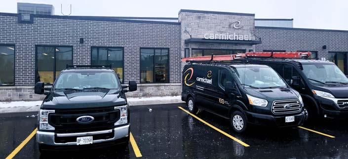
Carmichael Engineering’s new branch office in Belleville, Ontario provides a template for future projects.
By Doug Picklyk
MH18 BUSINESS
The Maintenance Plan
Ensure long-term customer satisfaction by offering service plans with every installation.
By Mathew Pottins


MH20 30 MECHANICAL MINUTES Electric Boilers: When and Where?
John Seigenthaler joins HPAC to talk about how electric boilers work and where they make sense.
MH24 DUAL FUEL The Big Switch
Modern controls can optimize hybrid gas/electric hydronic heating solutions.
By Curtis Bennett
MH26 HYDRONICS PRODUCTS

MH28 DESIGN Mathematics vs. Reality
Exploring the non-proportional relationship between heat output and flow rate.
By John Siegenthaler


MODERN HYDRONICS WWW.HPACMAG.COM MH4 SPRING 2024 CONTENTS COVER PHOTO COURTESY CARMICHAEL ENGINEERING
HPAC Magazine receives unsolicited materials (including letters to the editor, press releases, promotional items and images) from time to time. HPAC Magazine, its affiliates and assignees may use, reproduce, publish, re-publish, distribute, store and archive such unsolicited submissions in whole or in part in any form or medium whatsoever, without compensation of any sort. NOTICE: HPAC Magazine, Annex Business Media, their staff, officers, directors and shareholders (hence known as the “Publisher”) assume no liability, obligations, or responsibility for claims arising from advertised products. The Publisher also reserves the right to limit liability for editorial errors, omissions and oversights to a printed correction in a subsequent issue. HPAC Magazine’s editorial is written for management level mechanical industry personnel who have documented training in the mechanical fields in which they work. Manufacturers’ printed instructions, datasheets and notices always take precedence to published editorial statements. Contents Copyright © 2024 by Annex Publishing & Printing Inc. may not be reprinted without permission. Proud member of: We acknowledge the financial support of the Government of Canada through the Canada Periodical Fund (CPF) for our publishing activities. 111 Gordon Baker Road, Suite 400, Toronto, ON M2H 3R1 TEL: 416.442.5600 FAX: 416.510.5140 www.hpacmag.com MODERN HYDRONICS a supplement of Heating PlumbingAir Conditioning Magazine Doug Picklyk (416) 510-5218 DPicklyk@hpacmag.com David Skene (416) 510-6884 DSkene@hpacmag.com Amanda McCracken (647) 628-3610 amccracken@hpacmag.com Kim Rossiter (416) 510-6794 KRossiter@hpacmag.com Emily Sun esun@annexbusinessmedia.com Urszula Grzyb (416) 442-5600, ext. 3537 ugrzyb@annexbusinessmedia.com Peter Leonard (416) 510-6847 PLeonard@hpacmag.com Scott Jamieson EDITOR ASSOCIATE PUBLISHER NATIONAL ACCOUNTS ACCOUNT COORDINATOR MEDIA DESIGNER CIRCULATION MANAGER PUBLISHER PRESIDENT/COO Modern Hydronics


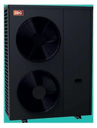
HPX 3 | HPX 5

• Renewable air energy with zero C02 emissions
• No refrigeration licenses required to install and service
• Advanced modulating temperature control
• Outdoor reset functionality
• Enhanced Vapor Injection (EVI) increases efficiency, lowers ambient temperature operating range to as low as -22°F / -30°C, and increases maximum supply water temperature
• Extremely quiet: 38-53 dB operational sound level
• 24V AC interface for easy thermostat connection
• Increased reliability with few moving parts
• Flow-proving and high limit safeties built-in
Easy-To-Install Decarb Solution For Year-Round Comfort


www.ibcboiler.ca | 1-844-HEAT IBC
PUMP This product meets a stringent set of our company’s internally defined sustainability standards
AIR-TO-WATER MONOBLOC HEAT PUMP HEAT
WHEN ONE ISN’T ENOUGH
Details for piping multiple hydronic heat pumps.
BY JOHN SIEGENTHALER
Multiple boiler systems have been used for decades.
They allow full heating capacity to be delivered when necessary, while also retaining high efficiency under partial load conditions compared to a single large boiler.
They also increase the resiliency of the overall heating plant. If one boiler is down for service at least one other boiler is likely ready to supply at least partial capacity.
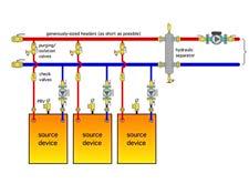
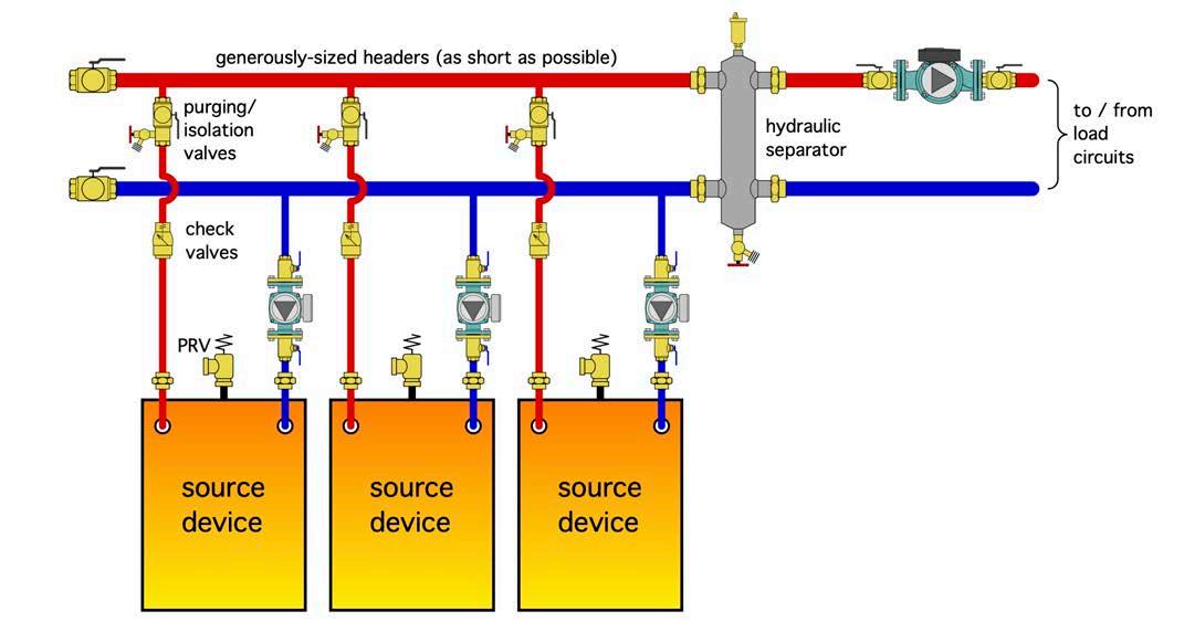
All the benefits of multiple boiler systems also apply to multiple heat pump systems. If the set up is configured to supply heating-only, or cooling-only, the generic system piping is identical to that of boilers, as shown in Figure 1.
Each “source device”, be it a boiler or heat pump, is piped in parallel with the others. Each has its own circulator that operates only when that source device is on. Each source device branch contains a check valve, purging valve and at least
one means of isolating the source device from the remainder of the system if it has to be removed or replaced.
The headers that supply and collect flow from the source devices should be short and generously sized (e.g., max flow velocity of two feet per second).
They lead back to a hydraulic separator that isolates the pressure dynamics of the source device circulators from that of the load circulator. The hydraulic separator also provides air and dirt separation.
It’s also possible to pipe a multiple boiler, or multiple heat pump system, using a single variable- speed pressure-regulated circulator along with motorized ball valves on each source, as shown in Figure 2 (page MH 8)
The variable-speed pressure-regulated circulator is set for constant differential pressure mode. It automatically adjusts speed up or down as one or more of the motorized ball valves opens or closes.
In theory, the number of source devices could vary from two up to whatever is needed to meet the design load capacity. However, there are diminishing returns on incremental gains in plant efficiency versus the added cost for piping, as well as space in a mechanical room tends to lead to a “practical” limit of four source devices.
Several manufactures now offer “modular” heat pump products that reduce the external piping requirements. In some cases the header segments are built into each heat pump.
SIMULTANEITY
Many commercial buildings, as well as some large custom homes, can require simultaneous heating and cooling. A common scenario is when the perimeter areas require heating while the “core” areas (e.g., those without exposed exterior
MODERN HYDRONICS WWW.HPACMAG.COM MH6 SPRING 2024
HEAT PUMPS
IMAGES: JOHN SIEGENTHALER
Continued on
Figure 1. Piping plan for multiple energy sources.
MH8
Modern Hydronics
surfaces) require cooling due to internal heat gains. Another scenario is when the building contains large glass areas that receive solar gains on sunny winter days.
There are several ways to design HVAC systems that provide simultaneous heating and cooling. They include variable refrigerant flow (VRF), variable air volume (VAV), four-pipe hydronic systems supplying air handlers or fan-coils, and water loop heat pumps.
Monobloc air-to-water and water-to-water heat pumps are another option for applications requiring simultaneous heating and cooling. Systems can be designed that allow any heat pump to operate independently in either heating or cooling mode.
In addition to space heating and cooling, such systems can be configured to heat (or pre-heat) domestic water or add heat to a pool through a heat exchanger. The piping configuration for such a system, based on monobloc air-to-water heat pumps, is shown in Figure 3 (page MH10)
This design use four risers, two for heated water supply and return, and two for chilled water supply and return. Although shown vertical in Figure 3, these risers can be in any orientation that suits placement of the heat pumps.
Flow in the risers is handled by a single variable-speed circulator set for con -
stant or proportional differential pressure regulation, depending on the length and size of the risers.
If the risers are relatively short and generously sized for a maximum flow velocity of 2 ft/sec., the circulator can be set for constant differential pressure control.
If the risers are long, and represent a significant part of the head loss through the heat pump assembly, proportional differential pressure control can be used.
In either case, the circulator automatically adjusts speed and flow rate as individual heat pumps turn on and off.
Each heat pump uses a pair of threeway diverter valves and a single two-way ball valve. The latter only opens when its associated heat pump is running. It ensures that there is no possible “short-circuiting” through inactive heat pumps.
Without this two-way valve the flow path through the heat pump remains open to either the heating or cooling risers when the heat pump shuts off. This creates a flow path, but with no heating or cooling input.
For example, if the heat pump shuts off in heating mode, the two three-way diverter valves remain in the heating position, which allows cooler heating water to flow through an inactive heat pump and then on to the hot water riser. This
“thermally dilutes” the temperature in the hot water riser.
Each set of risers leads to a buffer tank, one for heated water and the other for chilled water. For the system shown in Figure 3, heated water from the buffer tank is routed to multiple radiant panel manifold stations, and chilled water is routed to multiple fan-coil units.
These emitters are only examples. The heated water could also go to panel radiators, chilled beams, or even satellite air handlers.
Flow on the load side of the buffer tanks is also handled by variable-speed circulators set for proportional differential pressure mode. Each crossover between the distribution supply and return pipes has a zone valve that opens when that crossover is active and closes at all other times.
In addition to thermal buffering, each buffer tank provides hydraulic separation between the circulator supplying the heat pumps, and the load circulator.
The two three-way diverter valves and single two-way valve shown for each heat pump in Figure 3 could be replaced by four two-way valves. However, this likely adds to piping cost and also creates more points of potential failure.
The controls for this system would
Continued on MH10
MODERN HYDRONICS WWW.HPACMAG.COM MH8 SPRING 2024
PUMPS
HEAT
Modern Hydronics
Figure 2. Multiple heat sources using a single variable-speed pressure-regulated circulator and motorized ball valves.
The More You Install, The More You Earn
Triangle Tube is proud to introduce an industry leading loyalty program providing you with rewards for installing our best-in-class products. Join Connect and begin earning amazing rewards today!

Visit our website to learn more.

Caleffi 548 Series Separator Included (Shown Mounted) AVAILABLE NOW
LOYALTY PROGRAM
monitor the temperature of both buffer tanks. Since there is a limit to both heating and cooling capacity, and since any heat pump can only operate in one mode at a time, the control logic must prioritize heating over cooling, or vice versa.
In winter it’s likely that the priority would be heating, and thus operating the heat pumps to maintain the temperature in the heated buffer tank based on some
setpoint or outdoor reset schedule.
Cooling operation might only be allowed when the temperature in the heated buffer tank is within some differential of the target temperature.
During summer the priority would likely switch to cooling. The only heating load might be domestic water heating (if present), or early morning warming of select spaces using low mass heat emitters.
VARIATIONS
Air-to-water heat pumps with variable speed “inverter” compressors are becoming more common. It’s possible to leverage their modulating capacity control with staging to improve the load tracking ability of a plant. Doing so is analogous to how modulation and staging are now commonly combined with boilers.
Continued on MH12
MODERN HYDRONICS WWW.HPACMAG.COM MH10 SPRING 2024
buffer tank temperature sensor (S2)
Chilled
buffer tank
entire system filled with antifreeze solution All piping and components conveying chilled water must be insulated and vapor sealed VS ∆P circulator VS ∆P circulator VS ∆P circulator Air separator Air/dirt magnetic particle separator
Heated
Fan-coil
Zone
Balancing valve
valve
Purge valve
Balancing
Purge valve
Zone valve
valve
isolation valves PRV PRV Heat pump 1
VS ∆P circulator Dirt & magnetic separator
feeder diverter valves
motorized ball valve Heat pump 2 Heat pump 3
feeder
Balancing valves Purging/
Fan-coil
Fluid
2-way
Fluid
HEAT PUMPS
Modern Hydronics
Figure 3. A multiple heat pump set up for simultaneous space heating and cooling.


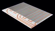
Ampex Insulated Radiant Floor Heating Panel ®


alleguard.com1 877-470-9991
Amvic Insulat ed PE X panel is designed to pr ovide the most cost -effec tive installation and per formance for hydronic radiant floor heating syst ems for new cons truction and r enovat ions. Ideal for basement s, car ga rages, slab-on- grade areas and exterior use for snow and ice melt applicat ions on driveways and walk ways.
fast er installation & optimum per formance design
Easier,
Save time, labour and money
ties
Walk in installation No st aples or
required
Superior tube insulation
multiple PEX
diameters
Integrated vapor barrier Available for residential and commercial Suitable for
tube
30 & 45 PSI
R12, R14 & R16 R10
Easyto assemble
Also available in
A heat pump with a variable speed compressor can reduce its capacity to about one-third of its rated output. If two were combined the overall turn-down ratio would be approximately 6:1.
This range of capacity modulation can eliminate the need for buffer tanks. Hydraulic separators would take their place, as shown above in Figure 4 System controls would monitor the supply on both the heating and cooling distribution system and operate the heat pumps based on load priority of the desired “target” supply water temp.
Another option is based on two threeway diverter valves at each heat pump,
but those valves must have three position settings: one to connect to the heating risers; another for connecting to the cooling risers; and a third that blocks flow through the heat pump when it’s off. This approach eliminates the need for a two-way motorized ball valve to block flow through a heat pump that is off.
Most three-way ball valves could provide the necessary positions. What’s missing (at least from my inquiries) is a three-position actuator. If anyone knows of a source I’m all ears.
The piping concepts shown can also be applied to water-to-water heat pumps sourced from a common earth loop. It
would also be possible to combine heat pumps with one or more boilers.
The market for heat pumps as alternatives to fossil fuel boilers is growing rapidly. Designers need to have concepts for deploying multiple heat pumps ready to roll. <>

John Siegenthaler, P.E., has over 40 years of experience designing modern hydronic heating systems and is the author of Modern Hydronic Heating (4th edition) and Heating with Renewable Energy (visit hydronicpros.com).
MODERN HYDRONICS WWW.HPACMAG.COM MH12 SPRING 2024
HEAT PUMPS
system filled with antifreeze solution
piping and components conveying chilled water must be insulated and vapor sealed
∆P circulator hydraulic separator PRV
VS ∆P circulator entire
All
VS
Balancing valves
Purging/
isolation valves Heat pump 1 diverter valves
∆P
2-way motorized ball valve
Heat pump 2 VS
circulator
temperature
VS ∆P circulator supply temperature sensor supply
sensor hydraulic separator
Fluid feeder
Modern Hydronics
Figure 4. Heat pumps with inverter compressors could eliminate the need for buffer tanks.

P-K SOLIS
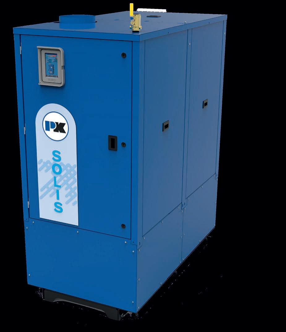

P-K SOLIS™ Capabilities
-1500-3000 MBTU
-Up to 96% Thermal Eiciency
-10:1 Mechanical Turndown
-Zero Clearance Capable for Side-by-Side Installation
-Narrow Footprint Fits Through Standard 36” Doorway
Our proprietary NURO® Touchscreen Control System is equipped standard on all SOLIS boilers. Designed to maximize boiler efficiency, the NURO utilizes the most advanced technology available.
Patterson-Kelley, LLC
877.728.5351
www.pattersonkelley.com
OPERATIONAL NET ZERO
Carmichael Engineering’s new branch office provides a template for future projects.
BY DOUG PICKLYK
From modest beginnings as a Montreal-based plumbing and heating business, over the past 100 years the family-owned Carmichael Engineering company has embraced an adventurous entrepreneurial spirit and developed into a nationwide commercial, industrial and institutional HVAC service, maintenance and designbuild contracting organization.
Founded by Ray Carmichael Sr. in 1922, today the company is led by Carmichaels’ grandson, Ray Jr., and has 23 branches and over 700 employees across the country.
In 2022 the business celebrated its centennial, while at the same time it was undertaking an ambitious project—designing and overseeing a ‘smart’ operational net zero building to serve as the new branch office for its Belleville, Ontario location.
WALK THEIR TALK
Carmichael made its name in service and maintenance and added Building Automation, Energy Services and DesignBuild divisions over the years. Although the company performed energy projects for clients, designing the new branch was their opportunity to walk the talk.
“We’ve been preaching this is the way to go,” says Carmichael’s Eric Rockarts, “Now we had to put our money where our mouth is by developing a building for our own team.” Rockarts, a 30-year employee with the company, launched the Belleville location in 1998 and served as branch manager for 24 years. He formally retired in June 2022, and then re -
MODERN HYDRONICS WWW.HPACMAG.COM MH14 SPRING 2024
PHOTO: DOUG PICKLYK
PROJECT
PHOTO COURTESY CARMICHAEL ENGINEERING
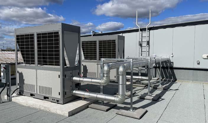
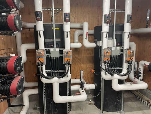
The two 20-ton heat pump air-cooled chillers provide heating and cooling.
The new Carmichael Engineering branch in Belleville, Ont. has been designed to generate as much energy as it consumes in a calendar year.
PHOTO: SEAN HAMMOND
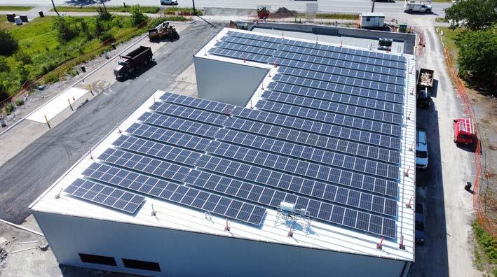
The building has enough solar to generate 125 kW of energy.

joined as part of the Engineering and Project Management group.
The goal for the new office was an energy efficient building that would produce as much energy using solar panels as it would consume in a calendar year with almost no reliance on carbon-burning fuels. And through its own building automation team it will be able to monitor and optimize the building’s operations. The project was a true team effort.
MECHANICAL SYSTEM
The new branch is around 22,000 sq. ft. in total, with Carmichael occupying 4,000 sq. ft. of office space in the front along with 6,000 sq. ft. of warehouse, and the building has two additional tenant spaces available for lease.
The warehouse and tenant section of the building is made up of pre-formed, pre-insulated, wall panels, and a double roof with about nine inches of insulation
and materials. The south facing office space has well-insulated walls, a lower roof surface and tinted high-efficiency double paned windows, all providing a tight building envelope.
Rockarts explains how the project’s mechanical design evolved over time.
“We wanted to add solar panels, so the energy group ran the models, balancing cost versus achieving the goal of operational net zero.”
The solar installer was able to accommodate all the panels on the building’s high roof, with the ability to generate 125 Kw of electrical energy. All the modeling is based on that capability.
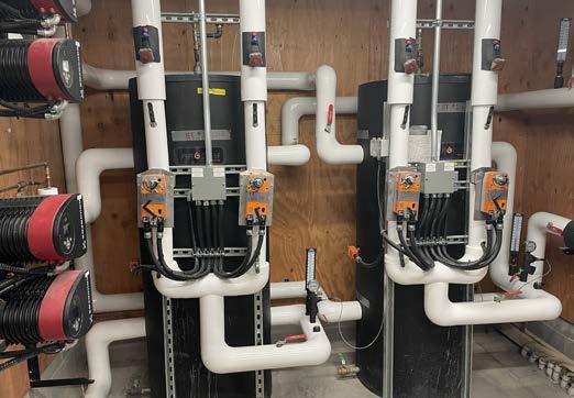
Initial design options included using geothermal or VRF, but ultimately the team selected LG air-cooled inverter scroll heat pump chillers for an air-to-water system, the first installation of these units in Canada.
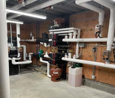
They installed two 20-ton chillers on the lower roof to provide heating and cooling. Using a glycol/water mix to prevent freezing, four pipes lead from the chillers into the building to satisfy either the hot water or chilled water buffer tank. The hot water tank is maintained at
Continued on MH16

MODERN HYDRONICS WWW.HPACMAG.COM MH15 SPRING 2024 Modern Hydronics
A DIFFERENCE MAKER Learn more at Lochinvar.com Raising the bar on energy efficiency and simplifying installation and operation, the Veritus Heat Pump Water Heater (HPWH) serves as a sustainable option providing energy savings and reliable domestic hot water for a wide variety of commercial applications. HPAC_AquaTech_Feb24.indd 1 2024-02-07 1:38 PM
Glycol loop from heat pumps to buffer tanks.
and the
When there are calls for heating or cooling in the building, the system draws from the tanks to a heat exchanger, where the distribution system for the occupied spaces is then fed a water-only supply of hot or cool water.
As Rockarts explains, “In January both chiller units would be in heating mode, and then come the shoulder seasons we can have chilled water and hot water working simultaneously. And, of course, cool water in the summer.”
A back-up gas-fired Lochinvar boiler is in place for supplemental heating if required, and it will only kick in below -15C.
HEATING/COOLING DISTRIBUTION
The system is designed using low temperature in floor radiant as the primary heating and hot water fan coils for zone tempering. The fan coils are also equipped with chilled water coils for water-based cooling.
Using all ECM-driven fan coils, it is designed with heating coils downstream from cooling coils, so they can provide dedicated dehumidification.
“We’re controlling plus or minus 0.1F of set point in all spaces,” says Rockarts. The systems are all controlled by Belimo electronic valves, and the building’s mechanical system is fully automated courtesy of Carmichael’s building automation system design using ABB-based controls.
“We also have Belimo Btu meters on everything,” notes Rockarts. “We know exactly where all of our energy is at, at all times.” As the generator of solar electrical power, plus heating and cooling energy, they can monitor all the energy heading to the tenant spaces to charge for consumption.
Because it’s an industrial site the demand for domestic hot water is very low, so instead of incorporating DHW off the heating water loop the team is using a 40-gallon domestic hot water electric heater to manage demand.
VENTILATION
The building operates a dedicated outdoor air system with ERV. “We wanted to precondition the outside air before it hit the fan coils, so it’s got an SCR controlled electric pre-heater on the incoming air to take the chill off, but then it has post heating or cooling from the heat pump chillers,” explains Rockarts.
The system design provides preconditioned constant ventilation with CO2 reset, whereby for all zones it calculates average CO2 and decides if it needs to increase fresh air or decrease to a minimum rate. “When there is no one in the office it will go down to a minimum ventilation rate to bring fresh air in, so the building starts fresh every day,” says Rockarts.
GRAND OPENING
The basic build was completed in June 2023 followed by commissioning. The BAS system operations are monitored by the company’s secure cloud-based Performance Analyzer platform. It was the joint forces of the Carmichael Divisions [DesignBuild, Engineering & Project Management, Building Automation and the Energy Group] that brought the project to life.
The Belleville team moved into the building in mid-October and celebrated a grand opening on November 21 st with the Mayor participating in the ribbon cutting along with Maddie Carmichael, the Vancouver branch manager and the fourth generation of the family to continue the legacy.
“As part of the new generation of Carmichael, we’re aiming to pioneer solutions that not only elevate the operation, efficiency and comfort of indoor spaces, but to pave the future for a greener world for generations to come,” said Carmichael, adding, “This building, in itself, represents the importance of, and our commitment to, sustainability.”
The Belleville branch is creating a template for future Carmichael facilities, and its Ottawa division is already working on a new space. <>
MODERN HYDRONICS WWW.HPACMAG.COM MH16 SPRING 2024
114F (45.6C)
chilled water at 44F (6.7C).
PROJECT
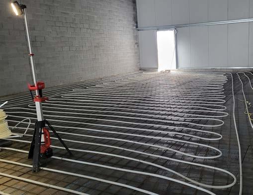
The entire building has in floor heating.
Buffer tanks in the mechanical room, one for hot one for cold.
PHOTO: DOUG PICKLYK
Modern Hydronics
PHOTO COURTESY CARMICHAEL ENGINEERING


CANADA’S HYDRONIC INSTALLATION CONTEST
WIN ONE OF THREE $2000 BUYING SPREES FROM EMCO!
Get your cameras ready. Be a part of Canada’s hydronic installation contest. Proud of your work? Better than the rest? It’s time to bring it on!
THERE WILL BE A WINNER IN EACH CATEGORY: COMMERICAL, RESIDENTIAL NEW-BUILD & RESIDENTIAL RETROFIT
ENTRY IS SIMPLE - send us pics of your installation. Include a brief description of the particular challenges that you faced with this installation and how you overcame the obstacles. Submissions are limited to one per contractor. Deadline to enter is July 31, 2024. All submissions will be shown at the Modern Hydronics Summit 2024. The three winners will also be announced by John Siegenthaler at the Summit. In addition to having your winning entry shared across our social media channels you’ll also be interviewed by HPAC’s editor and featured on the cover of the October edition of HPAC –

SEND ENTRIES OR QUESTIONS TO DPICKLYK@HPACMAG.COM WITH THE SUBJECT LINE “SWEET HEAT CONTEST”
BY...
SPONSORED

THE MAINTENANCE PLAN
Ensure long-term customer satisfaction by offering service plans with every installation.
BY MATHEW POTTINS
Hydronic systems are often praised for their efficiency and comfort. As we all know, these systems are an intricate network of components piped together to create a seamless heating experience in homes and commercial buildings.
However, their complexity can pose challenges for homeowners and contractors when it comes to maintenance and upkeep. A new system installation shouldn’t be a one and done with that customer.
In the world of HVAC services, unlike some other industries, contractors face a unique opportunity to not only retain customers but also expand their business. They can do this by offering comprehensive maintenance and service plans tailored specifically for the hydronic systems they install.
It’s understood, but it’s also important
to reflect on the many key components of a hydronic system and to educate your customer on the different parts and their proper servicing requirments:
Boilers or heat pumps: these are the heart of the system, responsible for heating the water or fluid before circulation and a source requiring regular inspection.
Pumps and valves: these components facilitate the movement of the heated liquid throughout the system, ensuring even distribution to the radiators, underfloor heating or other heat exchange points. Are they doing their job? (Let’s not get into the zoning with pumps or valves argument right now)
Radiators or heat emitters: these are the key devices that release heat into the occupied spaces. You might think radiators are as easy as install and walk away, but once you’ve introduced thermostatic radiator valves and auto air bleeders things start to change, homeowner education is always welcome. Or maybe you’re installing air handlers or fan coils which now have electronics involved.
Expansion tanks, makeup water
feeds and pressure regulators: these essentials are vital for maintaining proper pressure levels within the system and preventing damage.
Piping and insulation: the network of pipes through which the heated water travels, often concealed within walls or floors, require periodic checks for leaks, corrosion, or insulation integrity.
Condensate kits: providing a condensate neutralization kit and keeping the neutralizer fresh to ensure there is no corrosion in the plumbing and following local codes.
These are six major elements of a hydronics system that need to be maintained, and the average homeowner doesn’t want that servicing burden. So, let’s dig into how to make more money in hydronics while keeping your customer happy for the next 20-plus years.
CUSTOM PLANS
Every hydronic system can be a little unique, and this can be overwhelming to the common homeowner, which also means service plans can be specifically tailored to the heating system installed
ISTOCK/GETTY IMAGES PLUS MODERN HYDRONICS WWW.HPACMAG.COM MH18 SPRING 2024 BUSINESS
in each and every location.
Regular maintenance not only keeps your company fresh in the face of the homeowner. but it allows you to keep that system running smoothly for the long haul.
I recently installed a boiler with an air handler and in-floor heating in my house, and the first thing my wife said was: “This looks pretty complicated, what if something goes wrong?”
I replied: “I know a guy.”
OPPORTUNITY
There is no question that maintenance and service plans will benefit your customers, likely extending the life of their systems. And of course providing service plans offers benefits to your business as well:
Predictable revenue stream: service plans provide a consistent source of income, ensuring a steady cash flow.
Customer loyalty: by offering regular
service, you build trust and loyalty with end users, increasing the likelihood of repeat business and referrals.
Reduced emergency calls: regular maintenance helps identify and address potential issues before they escalate, reducing the number of emergency service calls for your team (how about we sleep on the weekends).
Extended system lifespan: proactive maintenance leads to a longer lifespan for system components, reducing the constant replacement of parts.
Market differentiation: contractors offering comprehensive service plans stand out in the market, attracting homeowners who prioritize the long-term health of their hydronic systems.
Upselling opportunities: during routine service visits, contractors can iden tify opportunities for system upgrades or improvements based on customer feed back, leading to additional sales (I know
we are a humble trade, but you have permission to do this).
BUSINESS VALUE
The addition of a comprehensive service plan with scheduled visits that you initiate by reaching out to customers annually, will not only keep your customer happy, safe, and lower their stress levels, but it will give you (the contractor) the opportunity to hold on to that customer.
And that’s what really increases the value of your company.

Mathew Pottins has worked with HVAC manufacturers and suppliers for over a decade, and his passion is in growing the industry. He runs Laylan Hydronics and HVAC Sales


MODERN HYDRONICS MH19 SPRING 2024 Modern Hydronics
<>
• 5,000 TIES PER CHARGE • HALF A SECOND PER TIE SAVE TIME SAVE MONEY WITH A ® OnSite_MaxUSA_Dec23.indd 1 2023-11-28 10:08 AM
ELECTRIC BOILERS: WHEN AND WHERE?

John Seigenthaler joins HPAC to talk about how electric boilers work and where they make sense.
BY HPAC STAFF
The latest installment of HPAC magazine’s 30 Mechanical Minutes, the free webinar series, took place January 31st and focused on electric boilers. In this episode, HPAC editor Doug Picklyk was joined by regular contributor and hydronics expert John Siegenthaler to discuss how electric boilers work, their advantages and drawbacks and some installation considerations.
This edition of 30 Mechanical Minutes was sponsored by Conforto, a division of Granby Industries.
ELECTRIFICATION
To begin, the discussion opened with comments about the recent AHR Expo that had taken place in Chicago just one week prior. The trend towards decarbonization and electrification was very evident on the trade show floor, with both
the host and Siegenthaler noting the large presence of new air-to-water heat pump demonstrations. But they both also commented on the growing number of electric boilers being shown, particularly products for the commercial segment of the industry. “Electric boilers were a hot topic at AHR Expo this year, and thus a great time for us to be talking about them here on 30 Mechanical Minutes,” said Picklyk.
In explaining just exactly how the technology works, Siegenthaler began by describing the electric boiler is a “relatively simple device.”
The units convert electricity through some type of a resistance element, similar to the elements in an electric water heater. “Typically, a residential electric boiler has a small pressure vessel, and there could be anywhere from one to as many as four heating elements,” says Siegenthaler. “While some of the large commercial electric boilers have more—I actually looked at one at the show that had, I believe, 15 different elements.”
All of these elements are controlled, and he acknowledged that in the past they were just turned on and off with con -
tactors, but today most of the electric boilers control the current that goes through the element, and they do that with solid state devices.
“So an electric boiler, unlike a fossil fuel boiler, can basically regulate heat output anywhere from 0 all the way to 100%,” says Siegenthaler.
He also explained how the controls within these boilers have progressed, some can not only maintain a pre-set boiler outlet temperature, even though the inlet temperature varies, they can also control based on outdoor reset, so as it gets warmer outside the supply temperature is reduced.
The devices can also be relatively small compared to fossil fuel boilers because they don’t need to accommodate the combustion chamber and gas assemblies.
PANEL CONSIDERATION
Something to beware of with electric boilers is the wattage that is being converted to heat. Siegenthaler provided a simple equation to convert kilowatts (kW) to Btu/h: just multiply kW by 3,413. For example, a 15-kW boiler is just over 51,000 Btu/h.
MODERN HYDRONICS WWW.HPACMAG.COM MH20 SPRING 2024
30 MECHANICAL MINUTES
Doug Picklyk (left) editor of HPAC and hydronics expert John Siegenthaler discussed what applications are a great fit for electric boilers. The complete video is available at youtube.com/@hpacmag.
“That would be high enough capacity to heat a house, and it’ll be served by a single phase, 240-volt circuit, and that would require almost 63 amps,” he says.
This is why the circuit panel is one of the very first things a contractor will want to check, especially in a retrofit situation where some older houses, especially those already using fossil fuel heating systems, might have 100- or 150-amp services.
“I don’t want to say that you can’t install an electric boiler with 100-amp service, but if that panel is pretty much filled up with breakers, you’d probably reach the limit.”
For new construction, using an electric boiler with enough capacity to heat a 2,500 sq. ft. modern house will require at least a 200-amp service, and that’s especially true if an electric vehicle charger is being added to the home.
TYPICAL USES
Electric boilers can be used for any hydronic distribution system that you would supply with a gas-fired or oil-fired boiler including radiant floors, panel rads, hydronic baseboard, etc. And an advantage of the electric boiler is no combustion, so there’s no issues with fuel supply or venting, and it doesn’t generate carbon monoxide (CO), so that’s one safety concern that’s eliminated.
In addition, Siegenthaler says that short cycling is really is not an issue at all with an electric boiler, plus they make very little sound. “You may hear a very small amount of sound coming from it, but that might be just the water moving through it.”
One of the unique potential advantages of an electric boiler over a fossil fuel boiler is the ability to coordinate their operation with time-of-use utility rates.
“You could easily set up controls that would allow an electric boiler to operate under the lowest-cost electricity,” suggest Siegenthaler.
Also, an electric boiler can take advan-
tage of solar photovoltaic systems. “If you’re dealing with net zero houses and you have photovoltaics, some of the energy that you’re producing can go directly into the boiler,” he says. “And if you have net metering, where any surplus electrical energy generated by the solar array would simply go back out through the meter at the same rate that you buy it at, essentially the utility becomes a battery for you.”
DRAWBACK
Aside from the high current draw, Siegenthaler touched on the thermodynamic efficiency concept called exergy, the idea that we can do a lot of things with electricity to maximize its thermal output. “We can run a compressor, for example, in a heat pump, and in effect, we get three or four times as much low-

MODERN HYDRONICS WWW.HPACMAG.COM MH21 SPRING 2024 Modern Hydronics
HPAC_Granby_Feb24.indd 1 2024-02-01 11:27 AM
Continued on MH22
grade heat into a building compared to just dissipating the energy into heat with an electric boiler.”
WHERE’S THE FIT?
When asked where he’s seen electric boilers in operation, Siegenthaler pointed to net zero and low energy houses or apartments as a possibility. “We’ve used electric boilers in very low load houses, in areas that have low-cost electricity or for clients that want photovoltaics and an all-electric solution.
“We’ve got a project in Minnesota that only has a 6-kW electric boiler that heats the entire house, and it does that with radiant floor heating in the basement and some panel radiators on the main floor. It’s not a large house, about a 1,500 sq. ft., but it’s extremely well insulated.”
Those homeowners asked, “Why not just put electric base board in versus a hydronic system?” His reply was about flexibility. They can use a low-cost electric boiler now, and switch to an efficient heat pump down the road.
“So electric boilers definitely have a niche. We like to use them as backup to air-to-water heat pumps, or even geothermal water-to-water heat pumps.”
He then shared details of a research project in Northern Maine where they are looking at off-peak rate structures and want to grab off peak electrical energy when it’s available and store it.
“It’s kind of a unique situation. They have a lot of wind turbines, and when they have a strong wind event the local utility has more energy than it needs, so they’re looking for ways to dump some of that capacity without curtailing operation of the turbines. I’ve actually been told that at some times they have negative utility rates, which means the utility would pay you to take this energy,” he says.
The project is using a prototype heat pump unit that can generate high water temperatures up to about 175F, where most air-to-water heat pumps are limited to about 130F.
In this case they can be tied into thermal storage, but most heat pumps really can’t get the temperature as high as an electric boiler, which could easily do 180F.
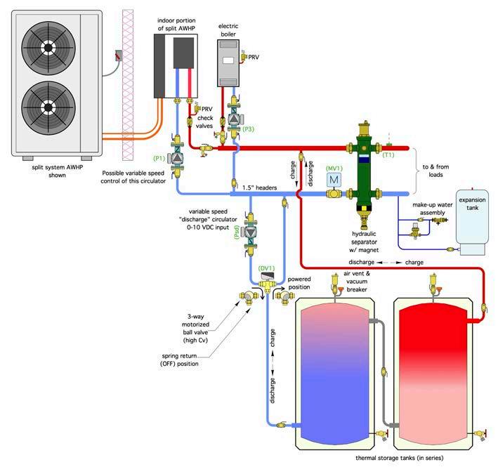
Siegenthaler shared a schematic where a heat pump and electric boiler are piped in parallel, and that enables either heat source, or both heat sources, to operate at the same time (Figure 1).
“If the heat pump wasn’t able to keep up with the load, or if the heat pump was down for service, the electric boiler could come on automatically.”
He adds that the controls in this system are designed to charge the thermal storage tanks up when the low-cost electricity is available, and then discharge those tanks back into the header, and ultimately to the hydraulic separator and the heat distribution system.
“The system is set up so energy can go into thermal storage from either heat source or it could go directly to the load.”
Some heat pumps can automatically
signal the electric boiler and its circulator would turn on.
He adds that heat pumps are much more complicated than electric boilers in terms of controls and sensors, and he suggests that there’s a better chance that a heat pump could go down for some service requirement.
“So we like to build electric boilers into systems as a backup to make sure the building has heat, especially in remote locations where you know that service may be much more than two hours away.”
In that situation, he sees an electric boiler as an ideal and relatively low-cost option compared to putting a fossil fuel boiler in as a backup.
The webinar closed with great questions asked by the live audience. To see the entire webinar visit hpacmag.com/ tech-pulse, where you can also find past editions of 30 Mechanical Minutes. All episodes are also available on the HPAC YouTube channel @hpacmag. <>
MODERN HYDRONICS WWW.HPACMAG.COM MH22 SPRING 2024
30 MECHANICAL MINUTES
Modern Hydronics
Figure 1. An air-to-water heat pump and electric boiler piped in parallel enabling either heat source to operate, or both at the same time.

• Robust stainless steel heat exchanger for longer life
• Residential and commercial applications

• Cascade and common venting between standard and recirculation models
• Certified Green Product™ by the Green Restaurant Association

See how we built a better tankless. ©2024, Bradford White Corporation. All rights reserved. BWHPAC0224
®.
Going tankless is an even smarter choice with Bradford White
Our Infiniti® GS & GR tankless gas water heaters are not only built to meet the demands of commercial and residential applications, they’re also an easy choice for the contractor.
THE BIG SWITCH
Modern controls can optimize hybrid gas/electric hydronic heating solutions.
BY CURTIS BENNETT
Well, it’s a good thing I’m a huge procrastinator otherwise I wouldn’t have an electrifying story for you today. So, yes, regular readers of my articles, I shocked myself again.
While downstairs working on a project for SAIT in Calgary I needed to test a control that has 120VAC. Easy enough you might think, but all I had around was a circuit board. Well, I found the power cord with the proper connector on it and plugged it onto the board.
The stupid part was that I had plugged the cord into the wall first. Normally this is not an issue, and I am careful, but as I was plugging the connector onto the board I touched the fuse. As you can imagine I yelped a bit.
It was not a huge shock, but enough to let me know how dumb and careless I can be sometimes when I am rushing. I went upstairs and asked my daughter, “Did you guys hear me yelp?”
Both my daughter and wife shrugged and went on about their evening. I don’t get much sympathy for being dumb in my house.
The focus of today’s article, like some others I write, can be a touchy subject in some areas of the country. I realize not everyone may agree with my point of view, and I’m ok with that. Our subject today involves bringing together new and shiny heat pumps with the now passé gas-fired boilers.

I say this with tongue in cheek, of course, although this topic is dividing not only our industry but also our nation. Now I won’t get into the politics, but we will see how these seemingly opposite sources of energy can be united and work together.
Decarbonization and electrification are the buzz words, and electrification of heating products in HVAC is accelerating to a crazy point. It does seem like all companies are trying to build heat pumps for the hydronics industry, whether these are water-to-water or air-to-water. And it seems like a new company is popping up every week.
Don’t get me wrong, I am all about saving the environment, but I am not about electrification at all cost. Like most things in life, we need a little balance here and the Big Switch can help.
The Big Switch is an idea of using the lowest cost energy resource available at a specific point in time.
Let’s start with a few statistics to realize the potential here:
• Space heating and/or cooling accounts for the most energy used in a building.
• DHW alone accounts for about 25% of the energy used in a building.
• Colder climates use more natural gas than hotter climates.
• Hotter climates use more electricity than colder climates.
• In Canada the average household uses about 10GJ of gas and about 830kWh of electricity per month.
• Return on investment (ROI) is important.
Controls in our industry are becoming more savvy and cost effective. By this I mean we can gather more information and not break the bank. Without this information gathering, our topic today would be a moot point. We need information to make the proper decisions on sav-
MODERN HYDRONICS WWW.HPACMAG.COM MH24 SPRING 2024
DUAL FUEL

ing energy and saving money.
In this Big Switch hydronic heating scenario I’m layout out, primarily we would be switching between an electrically operated device, usually an air-to-water heat pump, and a gas-operated device, usually a boiler.
Now you can have an electric element in this equation, but in the next issue of HPAC look out for PART 2 where I do all the calculating and you will see that model does not work out well, but it can.
The first question you are probably asking is, “Why the heck would we even bother with this switching business?” Good question reader!
I think the number one reason is money, but it’s a tie. Money and a greener planet are tied for first.
I am a huge proponent of ROI. If you put in a system that costs $50k for a hybrid or $20k for gas-fired only, how much gas can you buy for $30K? I know this is
a bit glib, but these are the facts.
And this scales up as well, because the cost of the installation also goes up with more equipment. I’m only pointing it out like this to show the monetary side of the equation.
Now there are financial incentives to install heat pumps, which is a good thing, and there are some other incentives to maximize efficiency of your house as well. So this all needs to be taken into account when making decisions.
Ok back to reality. How can we cost effectively use both electric and gas heating.
“Be green and save money?” you ask, “not possible.” Well, yes it is.
Now as the installations get bigger, so does the energy usage. Especially in the cases of DHW in commercial or large residential buildings. These loads are big, and they are predictable. Perfect for any number cruncher. Or perfect for any number crunching control in our case.
Electricity utilities everywhere are switching to Time-of-Day pricing, if it hasn’t hit your area yet it will.
What this means is when demand is low on the grid the price for electricity is low, and when the demand is high the pricing is high.
Most of the time this would not really work in our favour, but with the onset of energy calculating controls we can calculate the cost of running the gas side compared to running the electric side.
To do this we need utility data, the time-of-day gas pricing (which really does not change much) and time-of-day electricity pricing. We also need to know the Btu output vs input of the boiler and the total COP of the heat pump.
I will get into more specifics in Part 2 of this article, but for now just know we can figure out these values using thermal energy meters (like the ones that we make at HBX Controls) and with a little extra electrical input we can accurately calculate COP’s.
The reason we need to know these in real time is that Btu output and COP’s
change. Not so much for the boiler Btu output, but the heat pump COP changes with outdoor temperature.
So, by calculating in real time, or close to real time, we can know which system gives us the best value. By knowing this, and knowing the time-of-day pricing, we are then able to make the best decision possible.
Another factor here when using large DHW loads (as I said above, they are fairly predictable) is that we can precharge the tanks.
Why would we want to do this? Well, yes, I know the tanks will lose heat when just sitting there with no usage, but if we pre-charge the tank and actually “over charge” them when the time-of-day pricing is very low over night, there is significant savings that can be made.
In some jurisdictions the time-of-day pricing for overnight periods is 10 times less than peak hours. So, you can see even the small amount of heat loss you may have from pre-charging the tanks is far outweighed by the savings you can have.
We know that from around 6AM to 8AM is a huge load for DHW in large residential buildings. So, by pre-charging and overcharging the tanks before that happens can save a lot. We can only do this by knowing all the information, COPs, Btu’s and time-of-day pricing. They are all important. If you are missing one, the equation breaks down.
Ok, that’s a lot to chew on, so I’ll stop there. In the next article we will get into the math, so you can see the potential savings by making the Big Switch. <>

Curtis Bennett C.E.T is product development manager with HBX Control Systems Inc. in Calgary. He formed HBX Control Systems with Tom Hermann in 2002. Its control systems are designed, engineered and manufactured in Canada to accommodate a range of hydronic heating and cooling needs.
MODERN HYDRONICS WWW.HPACMAG.COM MH25 SPRING 2024 Modern Hydronics
IMANTSU/GETTY IMAGES PLUS
Taco Comfort Solutions expanded its light commercial ECM pump offering with the 1911ecm and 1915ecm. The 1911ecm is a 425-watt, selfsensing, close coupled, mechanically sealed pump with a high-efficiency volute, ECM motor and an integrated frequency drive. It provides a maximum 50 ft. of head and 105 gpm. The 1915ecm operates at 650 watts provides a maximum 65 ft. of head and 120 gpm. Both have control options that include constant pressure, constant speed, proportional pressure, 0-10Vdc and parallel pump alternation. Both pumps are both available in ductile iron for closed loop hydronic heating and cooling systems or stainless steel, NSF/ANSI/CAN 61 & 372 Commercial Hot Certified for domestic hot water applications. tacocomfort.com
RBI has expanded its Torus line of watertube boilers and water heaters to include smaller sizes from 300 to 1,000 MBH. The full line is now available from 300 – 4,000MBH. The boilers still include the HeatNet 3.0 digital touchscreen control and Tru-Flow fuel/air coupling system. Torus uses a pressure-driven air/fuel mixing system to provide up to 10:1 turndown. This pressure-driven system has no moving parts and eliminates common nuisance failures including ignition lockouts. An exclusive telescoping burner door system slides outwards offering full access to thecombustion chamber for easy annual inspection and service rbiwaterheaters.com
U.S. Boiler Company has introduced its Ambient air-to-water hydronic heat pump, a 5-ton capacity (rated at 60 MBH) unit that provides space heating at temperatures as low as -13F/-18C. Offering a COP of up to 3.95 and delivering supply temperatures of up to 140F, the Ambient monoblock heat pump uses R-32 refrigerant for high efficiency and low global warming potential, and its DC inverter enhanced vapor injection (EVI) technology is quiet, with operating sound levels as low as 39 decibels at two-foot distance. The Ambient Heat Pump is available with an optional dual-fuel controller for applications in extremely cold climates.
usboiler.net
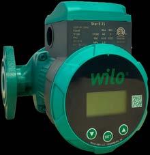
WILO’s new EC motor-driven circulator, the WiloStar E 21, is a four-speed circulator with three HD modes of operation for proportional control as well as an auto mode where the pump will automatically adjust to the system resistance to reach its best efficiency point with an LED display and adjustment buttons for easy set-up. Designed in a cast iron HT 200 pump body, it incorporates an advanced composite impeller and ceramic shaft. An optional check valve is also provided for parallel pumping applications. The fluid temperature range for the new Wilo-Star E 21 is 36°F to 230°F, with a maximum operating pressure of 145 PSI (10 Bar). wilo.com
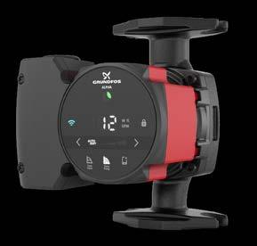
Grundfos has introduced its new-digital ALPHA high-efficiency ECM circulator. Its most efficient solution, the pump offers enhanced AUTOADAPT, Bluetooth connectivity and a touch-screen interface showing flow, power, and head for faster troubleshooting, and it offers guided setup, firmware updates, and with its functionality the company claims it is able to replace 95% of pumps in its performance space. It has also achieved a Hydraulic Institute Energy Rating of 193, demonstrating its improved energy efficiency. It also features improved system air venting for faster setup and can show trend data and and event log for easier system troubleshooting.
grundfos.com
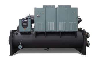
Johnson Controls has launched the York YVWH water-to-water dual variable speed screw heat pump, the first screw heat pump in North America to use R-1234ze refrigerant which has an ultra-low global warming potential (GWP) of 1. The YVWH can be operated in three modes: heating only, cooling only or simultaneous heating and cooling. It is the first screw heat pump that can provide water up to 176F (80C). The unit can provide 4,050 MBH of heating while simultaneously providing 200 tons of chilled water cooling at 41F (5C). The YVWH also features variable-speed drive and has excellent turndown that allows it to run with as low as 25% of the design-heating load.
york.com
MODERN HYDRONICS WWW.HPACMAG.COM MH26 SPRING 2024 HYDRONICS PRODUCTS
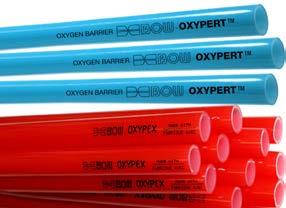
Now in Canada, BOW-branded Oxy-PERT and Oxypex tubing options offer benefits for a range of hydronic applications. Part of Orbia’s Building and Infrastructure business, Wavin, the BOW Oxy-PERT and Oxypex oxygen-barrier plastic pipes are designed to prevent the ingress of oxygen and are manufactured from recyclable ecofriendly materials. Both pipes provide noise and water hammer resistance. Oxypex PEX B can be used for both potable water and hydronic heating, while Oxy-PERT is a high-temperature flexible plastic pressure pipe suited for radiant slab heating systems for concrete, snow-melting applications, and baseboard heating. wavin.us
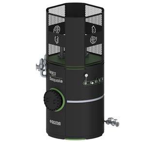
AERCO has introduced Sequoia, a high voltage immersed electrode boiler series for large commercial and industrial applications that require a virtually 100% energy efficient, emission-free heating solution. Available in seven sizes from 2,500 kW to 60,000 kW, the boiler family is simple to operate, its automatic controls provide operation over an output range of 10% to 100% (10:1 modulation) to optimize demand fluctuations while reducing operating personnel. Users can take advantage of lower energy rates during off-peak periods to reduce energy costs. Sequoia matches the capacity of large gas- or oil-fired boilers (up to 60 MW) in a much smaller footprint. aerco.com/sequoia
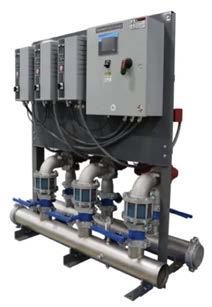
Bell & Gossett introduces the TECHNOFORCE HVAC package system, a stock skid system ready for installation in commercial HVAC and pressure booster applications. Offered in 40 pre-configured standard stocked models that come fully assembled, the package system consists of two to three e-1531 pumps, valves and control drives. Most models will fit through a standard 36-in. doorway. Flow ranges from approximately 200 to 3,400 gpm and each preprogrammed station is fully tested for flow and pressure up to 175 psi boost. A, LED colour touchscreen interface provides navigation of the system. bellgossett.com
The Hydronic Industry Alliance-Commercial (HIA-C), which promotes the use of water-based hydronic systems in buildings, has released version 6.2 of its Building Efficiency System Tool (BEST), an interactive commercial building HVAC system efficiency comparison application. The latest version focuses attention on energy use, including up to four selected HVAC system types in one life-cycle comparison report using historical design temperatures to determine peak energy demand and the energy utilization index (EUI). This free tool can help determine the return on investment for building owners when comparing different styles of HVAC systems. iapmo.org/hiac/
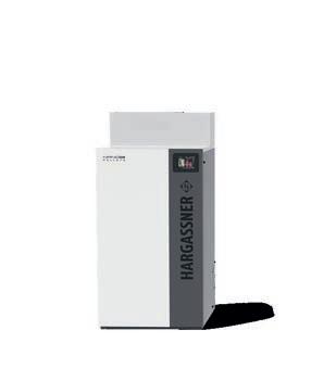

MODERN HYDRONICS WWW.HPACMAG.COM MH27 SPRING 2024 Modern Hydronics Hargassner North America Inc. 2100-181 University Avenue | Toronto | ON M5H 3M7 +1 437 837 2300 | office@hargassner-northamerica.com hargassner-northamerica.com P ELLE T | WOOD CH IP BOILERS Ex perience the world of sustainable wood heating Maximum comfort with automatic refueling & cleaning Maximum cost reduction with A+ efficiency Maximum flexibility with remote control CXE E L L ENTMANUFACTURER SIN C E 4891 Visit us! Scotia Horticultural Congress Versatile Powerful Compact Feb. 27 – 29 Las Vegas HPAC_Hargassner_Feb24.indd 1 2024-01-31 9:40 AM
MATHEMATICS VS. REALITY
Exploring the non-proportional relationship between heat output and flow rate.
BY JOHN SIEGENTHALER
When thinking mathematically, most people use proportions. For example, if someone is brewing coffee, and needs two scoops of granules for six cups, they intuitively know they need four scoops to make 12 cups.
So, if a person who thinks that way was told that a 100 horsepower (hp) engine, at full throttle, could make a certain car go 100 miles per hour (mph), and then was asked how fast would a 200 hp engine make the same car go, they’d likely answer 200 mph.
Unfortunately, nature doesn’t always work in proportions. Car racing fans know that it takes a lot more than 200 hp to push a race car around the track at 200 mph. It takes close to 800 hp to produce that kind of speed. Most of that power goes into overcoming the aerodynamic drag at those high speeds.
DISPROPORTIONATE
Hydronics also has its share on non-proportional relationships. One is how the
heat output and temperature drop across a heat emitter is affected by the flow rate through it.
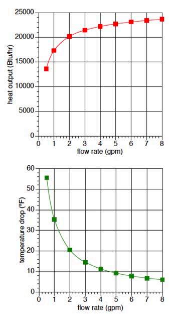
For example, suppose a given length of residential fin-tube was yielding a heat output of 5,000 Btu/h when operating at a flow rate of 1 gallon per minute (gpm).
If asked what would happen when the flow rate was increased to 2 gpm, while all other conditions remained the same, many people, including plenty who work with this hardware every day, would say that heat output would double. That answer might seem intuitive, but it’s not correct.
How about if the flow rate was increased from 1 to 4 gpm?
Surely a 400% increase would at least double the heat output.
To answer this just look at some Institute of Boiler and Radiator (IBR) output ratings from baseboard manufacturers. They’re given for a wide range of water temperatures, and for flow rates of 1 gpm and 4 gpm.
You’ll find the rating at a flow rate of 4

gpm is about 6% higher than the rating at 1 gpm, all other conditions remaining the same.
The reason lies deep in the workings of natural convection and thermal radiation between the outer surface of the fin-tube element and its surroundings.
It’s also effected by the forced convection between the water and the inner surface of the tube. The theory is complex, but the results are simply a reflection of how nature behaves.
MODERN HYDRONICS WWW.HPACMAG.COM MH28 SPRING 2024 DESIGN
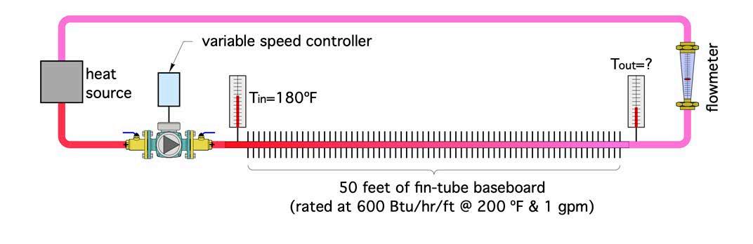
Figure 1. A simple hydronic circuit using fin-tube baseboard heating.

MAKING SOME MEASUREMENTS
Suppose you made up a hydronic circuit like the one shown below left in Figure 1.
This circuit contains 50 feet of residential fin-tube baseboard, along with a variable speed circulator, flow meter, two temperature gauges and a heat source. That heat source is always controlled so the supply water temperature into the fintube element remains at 180F.
You turn on the circulator at full speed, and the flow meter indicates 8 gpm. The water temperature entering the fin-tube baseboard is steady at 180F, and after a short time the outlet temperature of the fin-tube element stabilizes at 174F.
Knowing the flow rate and temperature drop along the fintube, you can calculate the rate of heat dissipation.
Where:
q = rate of heat output (Btu/h)
D = density of the fluid (lb/ft3)
c = specific heat of fluid (Btu/lb/F)
f = flow rate (gpm)
∆T = delta-T, temperature drop (F)
8.01 = a number that makes the units correct
You now have a measurement of the heat output at a flow rate of 8 gpm. Next, you reduce the speed of the circulator so
the flow rate drops by 1 gpm, wait for the outlet temperature from the fin-tube baseboard to stabilize, and write down the measured flow rate and outlet temperature.
You keep doing this for flow rates all the way down to 0.5 gpm, while the heat source always maintains the inlet temperature to the fin-tube baseboard at 180F.
Now that you’ve captured all this data, you can use it to calculate the temperature drop across the fin-tube element (e.g., delta-T), as well as the heat output rate from that element.
You then create graphs for heat output and temperature drop as a function of circuit flow rate.
They should look similar to the graphs in Figure 2 (next page)
IT IS WHAT IT IS
The graph of heat output (q) versus flow rate is probably not what you expected—especially if you think proportionally. It shows that heat output from the fin-tube element drops off rather slowly as flow rate decreases, until you get down to a flow rate of about 2 gpm. Below 2 gpm the heat output drops quickly with any further reduction in flow rate.
Although it might not be what you expected, this non-proportional relationship between heat output and flow rate is reality.
Continued on MH30


MODERN HYDRONICS WWW.HPACMAG.COM MH29 SPRING 2024 Modern Hydronics
IMAGES PLUS Complete solutions for energy production, storage, and distribution www.Roth-America.com Call 888-266-7684 Radiant, Snowmelt and Oil Storage HPAC_Roth_Feb24.indd 1 2024-02-01 11:51 AM
GRAFNER/GETTY
DESIGN
This characteristic is shared by all hydronic heat emitters: fin-tube, convectors, panel radiators, and even radiant panel circuits.
Heat output changes very quickly at low flow rates, but very gradually at higher flow rates. This trend also holds true at other supply water temperatures.
Next, look at the temperature drop across the fin-tube over the same range of flow rates.
First, it’s obvious the temperature drop doesn’t remain constant as the flow rate changes. The ∆T happens to be at the commonly assumed value of 20F when the flow rate is just a bit over 2 gpm.
As flow increases above 2 gpm, the delta-T keeps dropping, and at 8 gpm it’s only about 6F. When the flow is only 0.5 gpm the ∆T is slightly above 55F.
These delta-T values are the direct result of heat output. There’s nothing in this setup that forces the delta-T to stay at any particular value. There’s also nothing “wrong” with the fact that the delta-T is changing. It just goes where the physics takes it.
Another take away from this experiment is that there’s nothing special about operating a hydronic heating circuit with a temperature drop of 20F.
In Europe it’s common to see panel radiator circuits designed for design load delta-T of 30F or perhaps even higher.
European designers do this because it reduces flow rate, and reduced flow rate means small pipes and small circulators.
It also means lower operating cost. Over there, every watt counts. They won’t operate a circulator at 45 watts if it can create the necessary flow at 35 watts.
They care, and so should we, especially with increasing emphasis on mechanical systems for net zero buildings.
Radiant floor heating circuits can also be designed for different design load delta-T values. I like to design around 15F for floor circuits in areas that are expected to have “barefoot friendly” floors. The

smaller delta-T reduces variation in floor surface temperature a bit compared to what it would be at a delta-T of 20F.
However, in an industrial building, I may push the design load delta-T for the circuit up to 25F. That’s because heated concrete slabs in most industrial buildings don’t need to be “barefoot friendly.”
Slightly wider variations in floor surface temperature are hard to notice through a pair of work boots. Designing around slightly larger circuit temperature drops also reduces flow rate, which in turn decrease circulator size requirements.
IT’S NOT ALWAYS INTUITIVE
The relationship between the heat output of a hydronic circuit and the flow rate passing through it is not proportional.
Neither is the relationship between the circuit’s temperature drop and the flow rate through it.
Be sure to examine this relationship as you design future systems. Opportunities abound for reducing both installation and operating costs based on reduced flow rates and operating circuits at higher temperature drops. <>
John Siegenthaler, P.E., has over 40 years of experience designing modern hydronic heating systems and is the author of Modern Hydronic Heating (4th edition) and Heating with Renewable Energy (visit hydronicpros.com).
MODERN HYDRONICS WWW.HPACMAG.COM MH30 SPRING 2024
Find WHOLESALERS and PRODUCTS here: HPAC’s online BUYER’S GUIDE HPAC_Online BG filler_sept 23_GWJ.indd 1 2023-09-25 11:34 AM Modern Hydronics
Figure 2. Heat output and temp drop/flow rate.

SEPT 12, 2024
NEW LOCATION IN VAUGHAN PARAMOUNT EVENTSPACE!
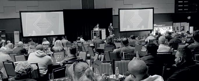
As always, the Summit will include our full slate of excellent speakers, 50+ exhibitors demonstrating the latest technologies, and unparalleled networking with hydronics professionals from all sectors of the trade.
Summit 2024 will again feature our Hydronics 101 sessions. Sponsored by we’ve added hands-on hydronic panel builds – the perfect training opportunity for newer technicians! Lots of prizes including, test instruments and Blue Jays tickets, will be won!


REGISTRATION NOW OPEN! SUPPORTED
SPONSORED
REGISTER NOW
BY
BY
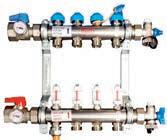
The Perfect BALANCE
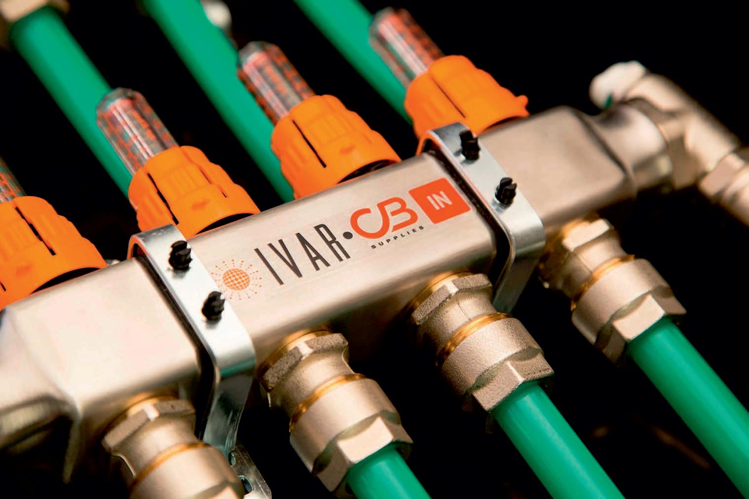
The ideal manifold and tubing for the distribution of heating fluid in radiant systems
Thanks to our ideal set-up for installers using our unique flow meters on each manifold loop, IVAR stainless-steel manifolds guarantee perfect system balancing, optimizing energy use, while providing premium thermal comfort.
Every manifold set is supplied with all components included in the box, ensuring a smooth commissioning process for radiant systems installers.
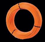
Pair the IVAR Manifolds with our premium VIPERT™ (PE-RT) Oxygen Barrier Tubing, manufactured specifically for radiant systems, and you have a winning solution every time.
Take advantage of our in-house hydronic expertise, including LoopCAD design and layouts customized for each of your residential and commercial projects.
1-800-268-7570
salesinfo@cbsupplies.ca cbsupplies.ca