4 minute read
Harvesting Polarization for Optical Signal-Processing Applications


Saif A. Al Graiti & Drew N. Maywar, Rochester Institute of Technology
The global market demand for higher-bandwidth communication networks is increasing exponentially. While opticalfiber networks provide low-loss, high-bandwidth transmission, the processing of optical signals often requires bottleneck-inducing conversion to & from the electrical domain, where the processing is performed on electronic signals. This bottleneck may be alleviated by expanding signal-processing capabilities directly in the optical domain itself. To this end, research performed around the globe has demonstrated optical-signal processing gates such as optical flip-flops for optical memory, optical AND gates, optical XOR gates, optical half-adders, and optical datawavelength converters. We have improved the performance of many of these gates by harvesting the dynamics of optical polarization, while also demonstrating a new kind of memory behavior that expands the fundamental understanding of a bistable optical signal produced by a nonlinear photonic resonator.

Demonstrated new concept for optical memory, whereby the state of polarization exhibits hysteresis.
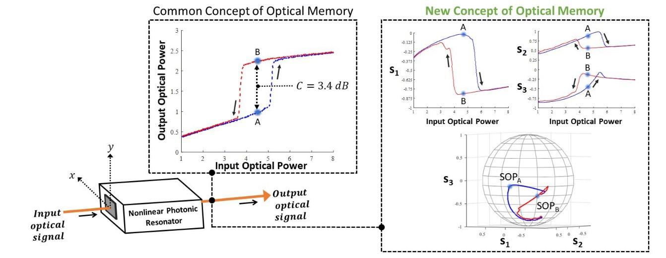
The common concept of optical memory produced by a nonliear photonic resonator is that the optical power exhibits a hysteresis curve, as shown in the left-most graph of Figure 1. For example, points "A" and "B" in the hysteresis curve exhibit different output optical powers for the same input power, with their occurance depending on the history (memory) of the input optical power. The power ratio between points A and B is quantified as the contrast C, where C is only 3.4 dB for the optical-power hysteresis curve shown Figure 1.
Our research reveals that, under the correct conditions, the optical signal may also exhibit hysteresis curves in its state of polarization (SOP). Such action is shown in the right-most graphs of Figure 1, using the Poincare sphere (bottom) and the three individual Stoke parameters (top). The Stokes-parameter graphs clearly reveal the bistable SOP. Each point along the optical signal has a specific SOP; for example, SOPA of the blue branch is different than SOPB of the red branch. This bistable action is a significant departure from the traditional optical-power hysteresis curves and we refer to the associated behavior as bistable polarization rotation. An optimized 30% rotation between SOPA and SOPB is measured in the lab using an optical polarimeter.
To obtain this new memory behavior, the nonlinear photonic resonator is selected that exhibits gain anisotropy & birefringence, and the input optical power is injected into both polarization modes of the resonator (which are aligned along the x an y axes shown in Figure 1). This memory behavior is made possible by the simultaneous occurrence of two underlying physical processes — dispersive optical bistability & nonlinear polarization rotation.
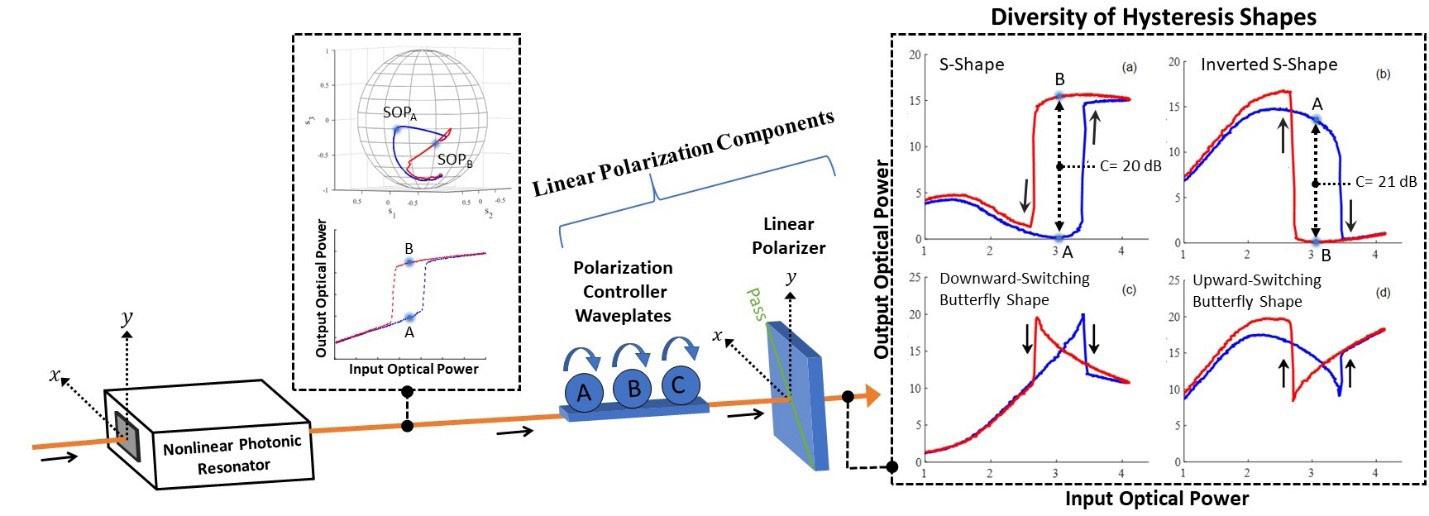
The ability to generate a bistable polarization-rotating signal opens up new capabilities for optical-signal processing. Here, we focus on the use of simple, linear-polarization components to convert the bistable polarization-rotating signal into a variety of optical-power hysteresis shapes. This conversion is depicted in Figure 2, where the bistable polarization-rotating signal is passed through a polarization controller and linear polarizer in series. By varying the rotation angle of the three waveplates of the polarization controller, the variety of hysteresis shapes shown at the right of the figure are achieved. The diversity of hysteresis shapes includes a high-contrast S-shape, a high-contrast inverted S-shape, and two butterfly shapes.
The high contrast S-shape is formed by adjusting the waveplates of the polarization controller to align the SOPA of the blue hysteresis branch to the block axis of the linear polarizer. Doing so increases the contrast to 20 dB, a substantial improvement from the 3.4-dB contrast shown in Figure 1. Such a hysteresis curve can serve as the basis of a combinational or sequential gate, such as an optical AND gate or an optical D-flip-flop.
The very shape of the hysteresis curve can be transformed by proper alignment of the polarization controller waveplates. For example, a high-contrast inverted-S-shape can be formed by adjusting the waveplates to align the SOPB of the red hysteresis branch to the block axis of the linear polarizer. Doing so "flips" the hysteresis curve upside down, with a measured contrast of 21 dB. The inverted nature of this hysteresis can serve as the basis of an optical XOR gate or inverted D-flip-flop.
More exotic hysteresis behaviors are seen in the two butterfly-shaped hysteresis curves in Figure 2. The formation of butterfly shapes is achieved by adjusting the polarization-controller waveplates in a way that results in an equivalent optical power exiting the linear polarizer at the center of each hysteresis branch. This condition is achieved with several waveplate configurations, yielding either an upward-switching or downward-switching butterfly shape.
Simple, linear polarization components are used to transform the polarization bistable signal into a variety of optical-power hysteresis shapes.
There are several features of this hysteresis-shape selection mechanism that promise to enhance the performance of combinational & sequential optical-signal processing. First, all hysteresis shapes exhibit the same switching input powers, allowing optical-logic gates based on these hysteresis curves to all be driven using the same optical control-signal power (i.e., shape-agnostic control power). Second, enhanced contrast is achieved for the S-shape and inverted S-shape hysteresis curves; such contrasts are at least 10 dB larger than previously demonstrated contrasts from photonic resonators. Third, all shapes are created using the transmission port of the photonic resonator; the transmission port lends itself to the concatenation of photonic logic gates. Fourth, the shape-selection mechanism occurs downstream of the nonlinear photonic resonator and without sending a control signal to the photonic resonator; this downstream control allows for the broadcast and site-dependent selection of the signalprocessing behavior. q
Mr. Saif A. Al Graiti is PhD candidate in the Engineering PhD program at the Kate Gleason College of Engineering, Rochester Institute of Technology (RIT) Drew N. Maywar is Professor of Communication Networks at the College of Engineering Technology, RIT


