
3 minute read
t up2.9 Pre-checks prior Initial Star


2.9 Pre-checks prior Initial Start up
Engine commissioning
ã
The local working safety rules must be strictly observed. Only service personnel necessary for first start up testing are allowed to be on the excavator. The operator must have read and understood the operation manual. Remove all tools and other not fixed material from excavator especially from moving parts.
Be sure that all hand rails, catwalks and steps etc. are correctly installed. Make sure that all hoses and electrical connections are correctly established (refer to the electrical and hydraulic circuit diagrams). Ex works, all disconnected hose lines and electrical cables are marked with identification numbers. Fill up the hydraulic oil tank and the fuel tank *. Check all fluid levels and correct if necessary *. Fill up or use filled respective grease container for the Central lube system and the Swing circle lube system *. Make sure that the shut off valve between the main hydraulic tank and the suction tank is completely open. Bleed the engine fuel lines and filters. Bleed the suction side of each main pumps *. Use adequate receptacle to collect out flowing oil. Be sure that the plug seal is in good condition. Tighten the plug securely. Fill up each main pump housings with hydraulic oil *. Bleed pump housing of the fan piston pump *. Check to make sure that the pressure relief cock for the hydraulic track tensioning system are CLOSED and the shut-off cocks in the crawler carriers are OPEN (refer to Illust. Z20371a). Open all lowering throttle valves of working attachment. At works are all closed. Do not forget to adjust the throttle valves after complete mounting of the attachment (Refer Service Bulletin AH02518 last edition).
Now the engine can be started and the machine can be operated for any additional assemblies. During and after starting pay attention to the instructions in the Operation Manual. *(Refer to the next pages).)
Z 25014
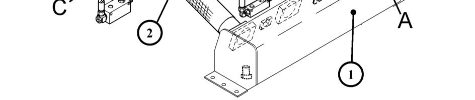
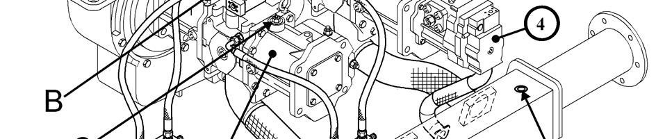
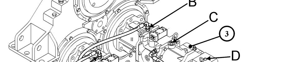

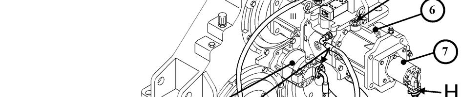
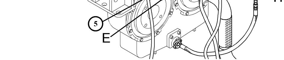
HYDRAULIC SYSTEM - Vent Hydraulic Pumps (Z25014)
1. Loosen vent plug (A) of suction oil reservoir (1). Retighten vent plug (A) when the out flowing oil is free of air bubbles. 2. Vent main pump (2) by loosening leakage oil line connector(B) and by opening vent valve (C). Retighten (B and C) when the out flowing oil is free of air bubbles. 3. Vent main pump (3) by loosening leakage oil line connector(B) and by opening vent valve (C). Retighten (B and C) when the out flowing oil is free of air bubbles. 4. Vent oil cooler fan drive pump (4) by loosening leakage oilline connector (D). Retighten (D) when the out flowing oil is free of air bubbles. 5. Vent control oil pump (5) by loosening vent plug (E) at the suction line flange. Retighten (E) when the out flowing oil is free of air bubbles. 6. Vent main pump (6) by loosening leakage oil line connector(F) and by opening vent valve (G). Retighten (F and G) when the out flowing oil is free of air bubbles. 7. Check hydraulic oil level and the whole hydraulic system for leakage.
REMARK
After changing the oil of the PTO gear vent the PTO lubrication pump (7) by opening vent plug (H) at the suction hose flange. Retighten (H) when the out flowing oil is free of air bubbles.


Z 24030


