
CONNECTABLE UNDER PRESSURE


CONNECTABLE UNDER PRESSURE
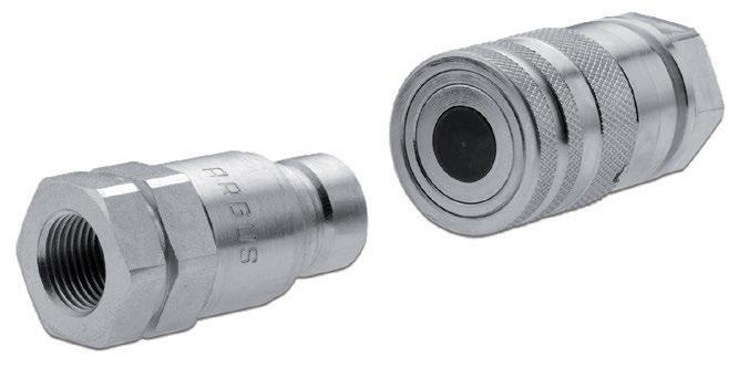
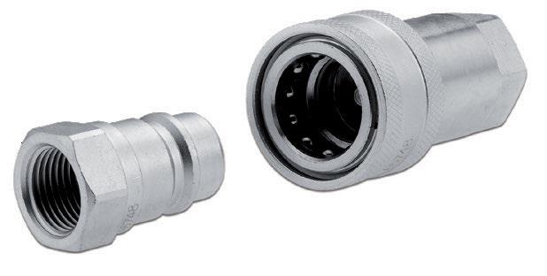
ISO INTERCHANGEABILITY
PUSH-PULL OPTIONS
SUPERIOR RUST RESISTANCE
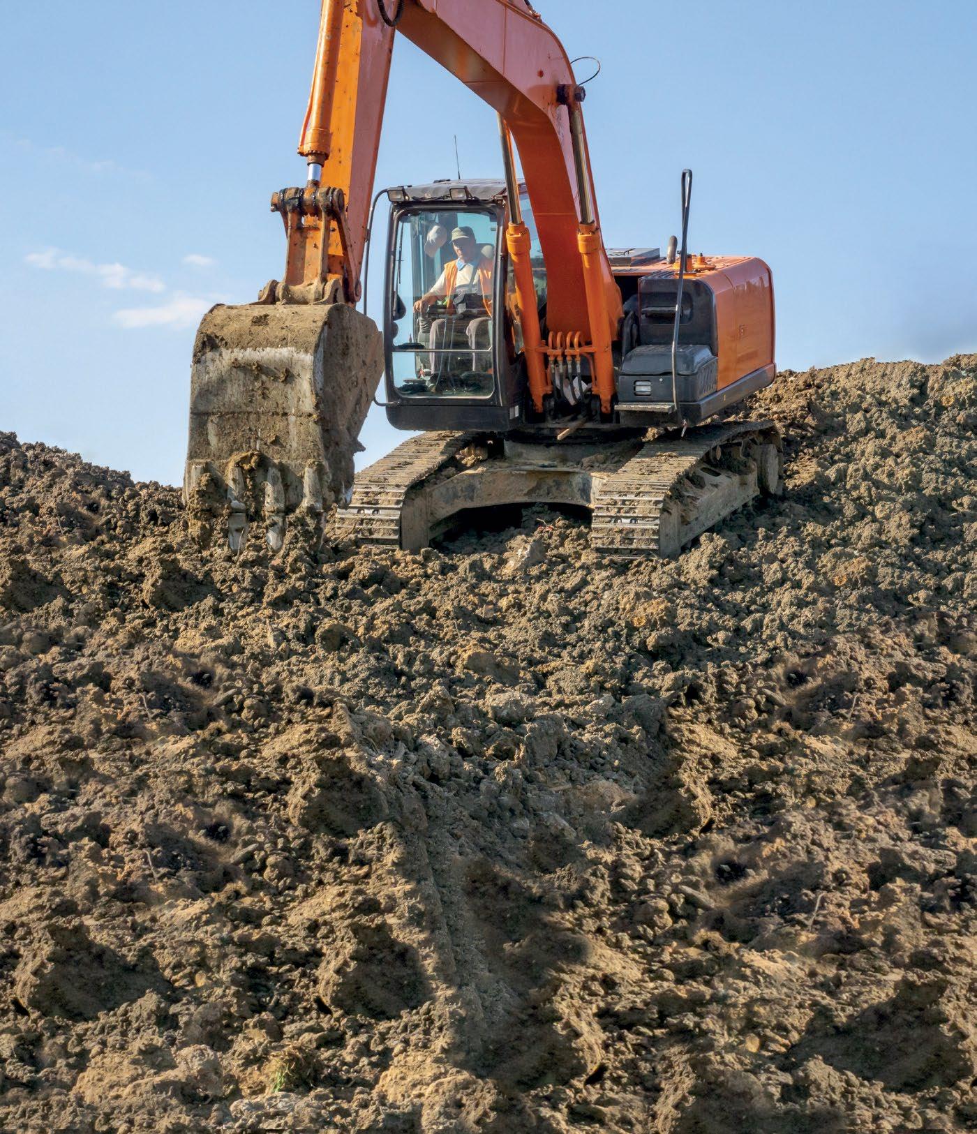

A COMPLETE PRODUCT RANGE FOR:
Discover the ITALIAN QUALITY of the full range of quick disconnect couplings: poppet, flat face, screw type with poppet or flat face valve, check valve, swivel connector, and multi-coupling system designed according to customer’s need.
ARGUS IS A BRAND OF THE ALFAGOMMA GROUP. VISIT US! BOOTH # 3638
6 Cover Story
Efficiently Comparing Filtration Media

Which hydraulic testing standards best assess flow conditions?

8 Case Study: Making an Electric Drive Hydraulic Danfoss transformed the drive system on feeder breakers working in a coal mine to meet customer demands.

12 Case Study: Connecting the Hydraulics of an African Dam In Liberia, IO-Link wired the hydraulic systems in a hydroelectric power plant quickly and efficiently.
16 IFPE Recap: Breaking Boundaries Exacts Excellence
Fluid power professionals gather with colleagues at the industry’s triennial trade show.

18 OTC Anchors in Houston for Marine Confab
The annual trade show tackles Arctic energy with three days of discussions.

30 Test Your Skills
Types and Applications of Compressors
Publisher’s Note: The information provided in this publication is for informational purposes only. While all efforts have been taken to ensure the technical accuracy of the material enclosed, Fluid Power Journal is not responsible for the availability, accuracy, currency, or reliability of any information, statement, opinion, or advice contained in a third party’s material. Fluid Power Journal will not be liable for any loss or damage caused by reliance on information obtained in this publication.


»
IF A HEADLINE like this in a fluid power magazine does not grab your attention, I'm not sure what will. But if you are with me this far, stick around because it only gets more irreverent.
"Heresy," you say and if you attended the International Fluid Power Exposition (IFPE) show this past March in Las Vegas and observed what I did, I would no doubt agree.
In partnership with the CONEXPO-CON-AGG show, IFPE featured over 375 exhibitors from around the globe, all converging in one location, many after a six-year absence. In addition to the massive number of component and equipment manufacturers, the education track provided over 170 unique sessions with 27 geared specifically to the fluid power minded. IFPE and CONEXPO-CON-AGG attendance was spectacular and has been reported as the largest in show history, even eclipsing the annual Consumer Electronics Show.
Among the many conversations happening - including those about the most comfortable shoes to wear on the show floor (with seemingly equal intensity, curiosity, and enthusiasm), were those about the various suppliers and what is new. Along with the regulars we expected to see, there were many newcomers from eastern and southern Asia and strong showings from Italian and other European manufacturers. There were many clever innovations such as LEAP award winner DGD Fluid Power and their Cartridge Flow Sensor; new spins on old technology like gear pumps with significantly reduced noise levels and directional valves optimized for energy efficiency and more component manufacturer options for machine builders (and those who would supply them) than ever before. Danfoss is no doubt bullish about the future of fluid power as they proudly promoted their acquisition of Eaton's Hydraulics Division and launched their very novel Digital Displacement Pump. Hardly the actions of a company that believes fluid power is a dinosaur destined for extinction.
Another interesting observation was how many large as well as small manufacturers are seemingly trying to "out-green" each other. But when pressed on how exactly they plan to make it happen, the answer often pivots to the goal rather than the current state or future reality. That is
not to say there are not great ideas such as variable speed pump drives, energy recovery, and other efficient hybrid technologies (there are), but many, especially in the areas of electrification do not address the need for massive physical infrastructure to support it. And as industries battle it out over the moving targets of energy efficiency, electrification, and ecology, the one constant that not only remains but is increasingly becoming the elephant in the room is just who on the factory floor is going to manufacture and repair all of this clever technology?
The younger talent needed in the skilled trades is not keeping pace with the demand as older employees leave the workplace and as increasingly difficult as it will be to find this new talent, it will even be more difficult to transfer the knowledge base unless they have the necessary skills to understand and apply it. According to The Manufacturing Institute citing a Deloitte study, as of January 2023, there were over 803,000 manufacturing job openings. And of the over 4 million U.S. manufacturing jobs that will likely be needed in this decade, over half are expected to go unfilled. Moreover, if we do not inspire more people to pursue modern manufacturing careers, these missing jobs could potentially impact the economy by $1 trillion in 2030 alone.
There is a lot at stake but at the same time, great opportunity for those willing to learn new skills and work hard in applying them. Data from the U.S. Bureau of Economic Analysis and Bureau of Labor Statistics, in 2021 shows that manufacturing workers in the United States on average earned $95,990 in salary and benefits. These are good jobs with good pay for those who have the skills. But to get there, industry, in partnership with government, academia, and the private sector must be at the forefront of the effort to prepare the workforce. And this effort must include fluid power as a viable and necessary technology.
So, as I reflect back on the success of another IFPE show, I am reminded of the saying that the more things change, the more they stay the same, and sometimes that is truer than we like to admit but this is serious stuff - the development of the next generation of talent is as deserving of the industry's love and attention as any new technology. But despite the seeming impertinence of this article and with all apologies to Mark Twain, I can say with absolute certainty the reports of fluid power's death by its technological rivals have been greatly exaggerated. The reality is that fluid power is very much alive and kicking. And wearing sensible shoes.
Innovative Designs & Publishing, Inc.
3245 Freemansburg Avenue, Palmer, PA 18045-7118
Tel: 800-730-5904 or 610-923-0380
Fax: 610-923-0390 • Email: Art@FluidPowerJournal.com www.FluidPowerJournal.com
Founders: Paul and Lisa Prass
Associate Publisher: Bob McKinney
Editor: Janis Adams
Technical Editor: Dan Helgerson, CFPAI/AJPP, CFPS, CFPECS, CFPSD, CFPMT, CFPCC
Marketing and
Social Media Consultant: Kristy O'Brien
Graphic Designer: Nicholas Reeder
Accounting: Donna Bachman, Sarah Varano
Circulation Manager: Andrea Karges
INTERN aTION a L FLUID POWER SOCIET y 1930 East Marlton Pike, Suite A-2, Cherry Hill, NJ 08003-2141 Tel: 856-424-8998 • Fax: 856-424-9248 Email: AskUs@ifps.org • Web: www.ifps.org
2023 BO a RD OF DIRECTORS
President: Scott Sardina, PE, CFPAI, CFPHSWaterclock Engineering
Immediate Past President: Denis Poirier Jr. CFPAI/AJPP, CFPHS, CFPIHM, CFPCCDanfoss Power Solutions
First Vice President: Jeff Hodges, CFPAI/AJPP, CFPMHM- Altec Industries
Treasurer: Lisa DeBenedetto, CFPSGS Global Resources
Vice President Certification: James O’Halek, CFPAI/AJPP, CFPMIP, CMPMM - The Boeing Company
Vice President Marketing: Chauntelle Baughman, CFPHS - OneHydraulics
Vice President Education: Daniel Fernandes, CFPECS, CFPSSun Hydraulics
Vice President Membership: Garrett Hoisington, CFPAI/AJPP, CFPS, CFPMHM - Open Loop Energy
DIRECTORS-aT-L a RGE
Stephen Blazer, CFPE, CFPS, CFPMHM, CFPIHT, CFPMHTAltec Industries
Cary Boozer, PE, CFPE - Motion Industries
Bruce Bowe, CFPAI/AJPP - Altec Industries
Bradlee Dittmer, CFPPS - Norgren/IMI Precision Engineering
Brian Kenoyer, CFPHS - Cemen Tech
Wade Lowe, CFPS - Hydraquip Distribution
Jon Rhodes, CFPAI, CFPS, CFPECS - CFC Industrial Training
Mohaned Shahin, CFPS - Parker Hannifin
Randy Smith, CFPHS - Northrop Grumman
Ethan Stuart, CFPS, CFPECS - Quadrogen
Bradley Wagner, CFPAI/AJPP - Manitowoc Crane Group
Brian Wheeler, CFPAI/AJPP, CFPMM, CFPMIPThe Boeing Company
CHIEF EXECUTIVE OFFICER (EX-OFFICIO)
Donna Pollander, ACA
HONOR a Ry DIRECTOR (EX-OFFICIO)
Ernie Parker, CFPAI/AJPP - Hydra Tech
IFPS STa FF
Chief Executive Officer: Donna Pollander, ACA
Communications Coordinator: Victoria Piro
Technical Director: Thomas Blansett, CFPS, CFPAI
Assistant Director: Jenna Mort
Certification Logistics Manager: Kyle Pollander
Bookkeeper: Diane McMahon
Administrative Assistant: Beth Borodziuk
Instructional Designer and Layout: Chalie Clair
Fluid Power Journal (ISSN# 1073-7898) is the official publication of the International Fluid Power Society published monthly with four supplemental issues, including a Systems Integrator Directory, Off-Highway Suppliers Directory, Tech Directory, and Manufacturers Directory, by Innovative Designs & Publishing, Inc., 3245 Freemansburg Avenue, Palmer, PA 18045-7118.
All Rights Reserved. Reproduction in whole or in part of any material in this publication is acceptable with credit. Publishers assume no liability for any information published. We reserve the right to accept or reject all advertising material and will not guarantee the return or safety of unsolicited art, photographs, or manuscripts.
»A SYSTEM THAT worked well for many years needed its electric motor changed. The company bought a 40-horsepower electric motor, but it was a different brand than the original one. After installing it and starting the system, the motor stalled and popped the overloads. The company discovered that the system could only run if they lowered the compensator setting. The operator could then increase the compensator, and it would run fine until the motor stopped. The company continued this start-up procedure of lowering the compensator to run the system.
When troubleshooting, workers noticed that the amp draw spiked higher than the motor’s nameplate rating of 40 horsepower. When starting the system, it drew even higher, causing the overloads to trip.
What could be the problem?
For the solution, see page 34.
Robert Sheaf has more than 45 years troubleshooting, training, and consulting in the fluid power field. Email rjsheaf@cfc-solar.com or visit his website at www.cfcindustrialtraining.com. Visit fluidpowerjournal.com/figure-it-out to view previous problems.
Cyclic flow conditions are nearly always present in mobile hydraulic applications. This makes the cyclic flow test lend itself to being a better representation of the environment to which hydraulic filters are exposed. The media developed to meet these standards offer better protection of hydraulic components.
Cyclic flow testing and alpha efficiency ratings are new to the industry, so it can be confusing when cyclic media and legacy synthetic media are compared.

Not all hydraulic filters are created equal, and neither are the testing practices that helped create them. The international standard ISO 16889 used to be the final word in hydraulic filtration testing. This multipass method was an accepted way to evaluate a filter’s performance. The method required filters to only be tested under steady flow conditions.
As anyone who has operated hydraulic equipment knows, steady flow conditions are a rarity. Hydraulics regularly operate under conditions of cyclic flow, meaning that pressures and flows fluctuate, causing contaminants to dislodge from filter media and re-enter the system, where they cause wear, drops in performance, component failure, and eventually unscheduled downtime of equipment and vehicles.
Because real-world conditions do not reflect the conditions dictated under ISO 16889, in 2021 a new standard, ISO 23369, was introduced as a multipass method of evaluating filtration performance in cyclic flow conditions. Both standards were then used to test hydraulic filter efficiency; whereas ISO 16889 provides a “beta” efficiency value, ISO 23369 provides an alpha efficiency.
Legacy synthetic media are prone to releasing contaminants under cyclic conditions, driving the need to develop new media that perform under these conditions. New technology like the fine-fiber Alpha-Web media designed by the Donaldson Company to perform to ISO 23369 are essentially in a different category than previous synthetic media.
It seems logical to compare efficiencies and initial pressure drop performance data for cyclic and steady flow media. For example, cyclic flow 10µ media and a traditional 10µ synthetic media have the same 10µ efficiency rating. However, the traditional 10µ synthetic media has an efficiency rating based on steady flow testing of ISO 16889. When testing traditional synthetic 10µ media under the cyclic flow test conditions of ISO 23369, this type of media only delivers 22µ efficiency.
This leads to the conclusion that before a comparison with a legacy media’s performance with a cyclic flow media’s performance, it must be assured that the comparison is between equal alpha efficiencies. In the example above, the efficiencies of the legacy and cyclic flow media are too far apart to be comparable.
Both methods of testing and media have merit. However, there are now two methods for testing hydraulic filter efficiency and media built to meet the older beta efficiency, which cannot be adequately compared to media built to meet the new standard, which uses alpha efficiency.
Instead, comparison is needed between two media that have equivalent alpha efficiencies. When testing a 10µ cyclic media under the steady flow method of ISO 16889, it delivers an efficiency of 6µ, compared with a legacy media that also has a cyclic efficiency at similar micron rating. For example, legacy media with 5µ beta efficiency and 9µ alpha efficiency can be compared to the cyclic flow media because the efficiencies are very similar. This is a key factor in comparing pressure drop ratings.
In a hydraulic system, as oil flows across a filter, flow is restricted, causing a reduction in pressure or pressure drop. In general practice, the more efficient a filter is, the higher its pressure drop. However, it must be noted that it is not always simple or direct.
Simply comparing pressure drop ratings between a 10µ legacy media and fine-fiber cyclic media shows that the legacy media’s pressure drop is 20% lower than the cyclic flow media. On the surface, it seems that the legacy media has a more desirable pressure drop performance.

When media are similarly efficient under cyclic flows, you can accurately compare pressure drop performance. Returning to the previous example, 10µ cyclic flow media and 5µ legacy synthetic media have been proven comparable in efficiency performance.
It is revealed, then, that 10µ cyclic flow media actually shows a pressure drop 20% lower than 5µ legacy media. In situations requiring high efficiency but where restriction is a concern, the cyclic flow media is the clear winner.
Before comparing the performance of different hydraulic filtration media, you must determine if they can be compared. Failure to ascertain the true efficiency of legacy media versus cyclic flow media can lead to filtration decisions that are anything but efficient for your bottom line. •

Feeder breakers are becoming increasingly popular in mining applications because they are efficient, maintenance friendly, and convenient. Modern feeder breaker systems are essentially composed of a feeder and crusher in a single, compact, low-profile, horizontal unit. By contrast, a more traditional feeder sizer arrangement uses two pieces of equipment to achieve the same result, but it requires additional structures and civil engineering support.
A feeder breaker has a number of advantages over a feeder sizer, including lower capital and infrastructure costs. Operational, maintenance, and running costs are lower with a feeder breaker as a result of its smaller vertical and horizontal footprint. It requires no primary sizer structure, access platform, or maintenance. Feeder breakers use less power and have fewer moving parts, which reduces inventory, maintenance, and storage costs.
The feeder breaker application at the mine in India was demanding for several reasons, including the proposed location at a depth of around 1 km (0.62 miles) below ground that is only accessible via 5 km (3 miles) of slope. As a result, reliability, uptime, and efficiency became major priorities.


Although an existing feeder breaker design is being used in South Africa, the end customer in India insisted on an all-hydraulic drive and auxiliary system, rather than the South African design of an electrical drive and auxiliary system hydraulics. Most current machinery in Indian coal mines uses hydraulics, and one of the principal reservations about flame-proof electrical drives centered on maintenance, as flame-proof electric drive failure and replacement is costly compared to hydraulic alternatives.

As a further requirement, there was agreement that switching from the existing fixed displacement gear pump to a load-sensing piston pump would improve energy efficiency and allow optimization of the cooling unit to minimize space requirements, easing transportation during the long journey underground.
Continued on page 10
Continued
FLSmidth feeder breakers contain several subsystems, including a breaker drive, conveyor drive, track/tram drive, and a bed-lifting system. The breaker drive supports the sizing of the extracted coal before transferring it to the main conveyor, while the machine conveyor feeds the coal toward the breaker drive for sizing before transferring it to the main conveyor. The track drive maneuvers the feeder breaker within the mine.
Due to its demanding work and location, optimal system design and product selection were critical, centered on components such as the pump, valve block, hydraulic motor and drive, tank, filters, air breathers, and more. The user insisted on in-field commissioning and fine tuning of such an advanced system, where the support of on-site software engineers would prove pivotal.

With ever-tightening margins in industrial mining, the efficiency of individual pieces of equipment alongside operational and maintenance processes becomes increasingly critical. Making the right decision regarding pump design can deliver considerable advantages in safe, efficient, and profitable mine operations.
With these thoughts in mind, both closed- and open-circuit axial piston pumps from Danfoss formed part of the solution. The breaker drive employs a closed loop pump with remote hydraulic pilot control. Notably, the breaker drive’s hydrostatic system is in continuous operation, determining the choice of a closed-circuit solution, which is more energy efficient than an open-circuit counterpart. There was also a constraint on space, and using a hydrostatic closed loop pump considerably reduced the associated tank size.


Danfoss’s open loop pressure-compensated pumps serve the conveyor, track, and auxiliary (cooling, machine lifting) drives on the feeder breaker system.
Danfoss open loop piston pump
The exact efficiency gains are difficult to estimate; the previous feeder breaker design used in South Africa meant that no benchmark comparisons were available. However, theoretical efficiency gain is estimated to be 15-20%. Piston pumps also offer a long operating life subject to the consistent implementation of service criteria and scheduled cleaning routines.


Complementing the pumps is a Danfoss modular proportional valve block with explosion-proof coils that negate potential ignition sources in mines, where accumulated coal dust and gases such as methane are hazardous. These electrohydraulic valves integrate multiple functions in a compact dimensional envelope. Providing an almost infinite number of configurations, from simple load sensing to CAN bus communication, for smooth and consistent machine control.
Additional Danfoss components such as hoses and screw-in and proportional cartridge valves contributed to the turnkey solution, alongside third-party and local products like hydraulic motors, filters, pressure sensors, and stainless steel tank with temperature and level sensors.
The selection of a Danfoss programmable controller hinged on its ability to facilitate easy management of every system function, coupled with fast processing power, a software-configurable I/O system, and rugged construction to handle the mine environment. Notably, the system required a controls architecture featuring an intelligent interlock system. Monitoring interlock conditions via pressure, temperature, and level transducers would facilitate safe operations for mine employees
The Danfoss software and applications team worked closely with FLSmidth to develop a complete turnkey solution. In essence, when the conveyor and breaker drives are running, the track/tram drive cannot function as the hydraulic system level interlocks with the electrical motors. The intelligent system also includes safe operation mode for emergency conditions, and auto run-off to provide additional safety. In addition, there is a built-in diagnostics function, so if anything goes wrong the system can help to quickly identify the potential cause. Of particular note, the system solution is completely digital with no manual lever operation required for normal operational control. However, manual overrides are provided for track drive operation in case of emergency operation.
Another issue for the end user was space. With the feeder breaker located deep underground and at a location accessible only through small tunnels, it was clearly an unrealistic proposition economically to change the tunnel geometry so it could accommodate a large cooler for the feeder breaker. A sensible solution required reasonable working temperatures for the feeder breaker. With ground surface temperatures outside the mine as high as 50°C (122°F) in summer, the temperature inside the mine can reach 35°C (95°F), even at a depth of 1 km (0.62 miles).
Again, the switch from a gear pump to a piston pump provided the answer. That’s because, when using a gear pump or other type of fixed-delivery pump, heat becomes an issue, which in turn necessitates larger coolers.


Piston pumps, on the other hand, are more efficient thanks to reduced heat losses, particularly in the closed loop system used on the breaker drive. Although it is impossible to eliminate the need for a cooler entirely, adopting a piston pump design allows for smaller cooling equipment and an optimized schematic layout that facilitates easier transportation and installation.


By recommending a move from a flame-proof electrical system to hydraulic drives, Danfoss ultimately resolved all the mine application challenges involving reliability, energy efficiency, excess heat, space constraints, and fire hazards. The company successfully commissioned the first feeder breaker to the customer’s satisfaction, an outcome achieved by working closely with FLSmidth and the end user during the customized design and build process, including on-site installation and testing. Further support was provided by a software engineer stationed at the customer site to fix any unforeseen issues and ensure all functions worked as intended.
The Indian mining company enjoys the benefits of major improvements in production efficiency and mechanical reliability that in turn deliver increased throughput, enhanced safety, and drastically reduced downtime with lower maintenance and energy costs.
Danfoss and FLSmidth achieved all this for an application that required rugged machinery to work flawlessly in cramped, harsh, and hazardous conditions. That is testament to both companies’ vision and teamwork, which will pay dividends long into the future. •
 By Wolfgang Zosel, Balluff
After more than 20 years of interruption, the dam’s four turbines began feeding 22 megawatts each into the power grid. The origins of the Mount Coffee dam, which lies 30 kilometers northeast of the capital, Monrovia, go far back. The dam was built in 1966 but largely destroyed during the Liberian Civil War from 1989 to 2003. By the time the Liberia Electricity Corporation had contracted an international consortium of companies to rebuild the dam, extensive parts of the plant had literally turned to grass.
The job included the complete rebuilding of the hydraulic steel structures, consisting of the electronics, drive technology, and control systems. The dam’s ten radial gates and four intake gates for the turbines needed refurbishing. The radial gates control the water level on the upstream face of the reservoir and are driven by cable winches. The intake gates bring the water to the
turbines and block the inflow (shut-off valve) if a fault such as a break in a pressure line occurs. The drive is hydraulic, including electric and hydraulic drive units as well as various supporting systems.


The Mount Coffee dam, 160 meters long with 10 radial gates each 15 meters wide, is not the largest of its kind. Nevertheless, several dozen analog and digital signals must be collected across the entire dam over long distances and made available to the control level.
In terms of the complexity, the numerous tasks to be performed in the peripherals, and the required level of networking, the dam is essentially a widely distributed industrial system, according to Bernd Schneider, Balluff’s industry manager for energy. Balluff developed IO-Link as part of the founding consortium in 2006. Today IO-Link is a global standard (IEC 61131-9) for setting up intelligent solutions for industrial automation.


As a point-to-point connection with a high degree of standardization, the universal interface is indispensable for Balluff and its customers. Not least when simple wiring, overview, and the highest requirements for diagnostics and configuration are high on the wish list. And this is almost always the case in today's highly automated systems.




Time and increasing cost pressures are also a central topic in power plant construction. It is presumed that systems integrators will thoroughly test their components themselves before they are installed in the shortest possible time far from home, where they must function smoothly and error-free within the overall system.
In many areas of the industry, copper cable and junction boxes are still used all the way up to the control level, representing a huge investment in materials and time. IO-Link is a game changer. The digital interface is a point-to-point connection independent of a field bus, a single standard industry line is required. The digital technology enables the exchange of process and service data, as well as events and analog signals, with the best signal quality. This way customers can monitor the sensors within the production process down to the last meter and perform diagnoses
the analog signal into a noise-immune digital signal. Stub lines from a Balluff IO-Link master carry the data to the control level via Profibus DB. Because the system is redundant, the wire is divided in two sections, with a maximum of 75 meters of cable required.
Using standardized cable and connectors instead of individual wiring cuts the cabling time in half. And with IO-Link, each module can be tested in advance at the factory and simply plugged in, which noticeably reduces costs. Wiring mistakes are virtually eliminated, while IO-Link also saves space and provides a clear overview. Internationally active companies especially appreciate the advantage that IO-Link can be used essentially with any bus system: the complete structure beneath the bus level always remains the same, only the bus nodes need to be adapted for a particular country.
Working with other contracted companies, Balluff engineers developed a coherent electronics concept with the goal of simple wiring, standardization, and modularity. Two Balluff IO-Link masters are installed in a switch box at each of the 10 radial and four inlet gates to collect up to 20 different signals in the field. The signals originate from inductive or mechanical limit switches, sensors for determining the rotation direction of the radial gates, control-, regulating- and shutoff valves, signal lamps, and illuminated switches.
Two IO-Link masters are installed at each hydraulic station for linking the involved sensors and actuators there as well. Without exception, the components in the field are connected using three-wire standard cable type and M12 connectors. Where analog signals from a particular sensor cannot be directly processed, a compact Balluff adapter plug converts
The bidirectional communication standard provides greater perspective in other ways. The IO-Link diagnostics information enables quick localization for fault and error correction, which reduces unnecessary downtimes. This is a benefit wherever systems aren't located close by, and specialized personnel are not available when issues arise. With IO-Link remote, maintenance down to the process level is possible. In addition to clear diagnostics and action instructions when a fault occurs, preventive maintenance concepts are easy to implement.
The offering of universally applicable IO-Link products, including those with built-in condition monitoring capabilities, continues to grow. For the user, this brings further opportunities for optimization in wiring, diagnostics, and configuring. •


The International Fluid Power Exposition, co-presented with CONEXPO-CON/AGG, held at the Las Vegas Convention Center saw the fluid power industry crushing precedents set in prior years. Innovation and invention made a great showing at the event.


After lowered attendance in 2020 due to Covid, the statistics for this year were staggering with 139,000 in attendance representing 36 countries, spread over an expanse of 3 million square feet of space, an amount 10.5 percent larger than 2020.

Numbers show a record high:
6% attendance increase over 2020.
2400+ exhibitors, including 603 new-to-the-show.
24,000+ international registered attendees.
91,000+ education tickets purchased.
"The success of CONEXPO-CON/AGG & IFPE 2023 is a testament to the resilience and strength of the construction and fluid power industries, which has continued to adapt and innovate despite the challenges of the past three years," said Marcia Klein, Treasurer of Casappa Corp., and show chair of IFPE.
Exhibitors boasted offerings proving despite a setback of recent years, due to struggles amidst the supply chain, that meaningful growth in the fluid power industry is ramping up at an encouraging pace, with new technology following suit.

The fluid power industry is constantly striving to become more efficient, more sustainable, and more power-packed, with consistently improving products. In this vain, new products were unveiled at IFPE and connections were made for future trend setting advances.
To quote one attendee, who was onsite for the five full days of the show, speaking to anyone who chose not to be in attendance, “You missed a good show!” With that bold statement, set your calendars now and plan to attend North America’s #1 trade show and conference showcasing fluid power, power transmission and motion control in 2026 at the Las Vegas Convention Center.
IFPE 2026 will be held March 3-7, at the Las Vegas Convention Center.


Back on its regular schedule after COVID interruptions a few years ago, the Offshore Technology Conference anchors May 1-4 at Houston’s NRG Park.

Exhibitors at the annual trade show launch and display products and new technologies for the offshore sector. Companies highlight equipment, digital solutions, and process improvements that promise progress toward a lower-carbon industry. Professionals share expertise in efficiencies in drilling; production and operations; health, safety, and environment practices; and innovative uses of data and systems.
Attendees can take advantage of networking opportunities, educational sessions, and topical discussions, including a series on the future of energy in the planet’s northern-most reaches.
OTC has also scheduled a number of sessions and networking opportunities focused on Arctic opportunities for oil, gas, mining, and renewables. OTC offers three days of discussions on the Arctic region’s potential. Here are the scheduled sessions.
For more information about OTC, visit 2023.otcnet.org.
1 May MON 2 May TUE
Facing the New Reality Energy Applications in the Arctic Speed Bumps on the Road to Energy Transition Outlook and Challenges for Critical Minerals and Renewable Energy
For more information about the series, visit 2023.otcnet.org/arctic-offshore-energy.
May WED
Beyond
for Arctic


»IFPS RECENTLY ANNOUNCED a grant program for educators to take their first certification test for free. Educators already certified through IFPS can use the grant for certification testing or for an Instructor Training Workshop to become an Accredited Instructor or Job Performance Proctor. High school, tech school, career center, college, and university educators can apply with proof of employment. Applicants must be IFPS members. Applications must be received six weeks before the workshop or certification test. Educators are eligible for a free certification test (initial or retake) or a free ITW registration fee. Additional proctor fees may apply. Costs for study manuals, books, educational materials, and travel are not covered. Grants are issued via coupon code after the applicant’s employment is confirmed. For more information, visit www.ifps.org/ certification-grant-for-educators-2.
ONLINE AT-YOUR-OWN-PACE training module takes the IHM and MHM study manuals and brings them to life! The mechanic training modules heavily emphasize maintaining, repairing, and troubleshooting hydraulic systems. These modules also include the basic principles of fluid power and the operation and construction of the most common hydraulic components found in the system.
These modules are a great tool for someone preparing for an IHM or MHM certification test, someone looking to boost their skills, and even makes an excellent onboarding tool for entry-level mechanics!
Our IHM and MHM certification study manuals were transformed from traditional black/white print into a full color, animated, interactive online learning platform!
• Schematics are color coded and animated
• Contains ISO 1219 symbology
• Full-color graphics
• Chapter review questions - interactive (you’ll know immediately if you’ve grasped the chapter information)
• Voice-over for text for auditory learners
• Three additional online pre-tests
• Safety and Energy Tips throughout Cost is $349. Multiple-user pricing for five or more! E-mail sales@ifps.org for details.
»A RECENT STUDY found that more than 68% of participants cited a lack of confidence as the biggest stumbling block to a student’s ability to succeed in math. If math is a stumbling block for you, or if you are preparing to take a certification test, this online at-your-own-pace training module transforms the IFPS math book into an interactive learning tool!
Dan Helgerson, CFPAI, will teach fundamental fluid power math skills and build on that foundation to explain the calculation of more complicated formulas. Each section includes step-by-step video instructions on how to solve complex fluid power math problems.
1. Welcome to the Fluid Power Math Workshop



2. Understanding the Order of Operations –PEMDAS
3. Units used in IFPS Fluid Power Math Equations
4. Math Basics
5. Circles
6. Various Math Equations
7. Fluid Power Formulae
8. Calculating, Volumetric, Mechanical and Overall Efficiency
9. How to Size and Select a Fluid Power Cylinder
10. Calculating Fluid Velocity
11. Detailed Explanation and the Importance Triangles in Fluid Power
12. Understanding Reaction Forces
13. Jib Boom Calculations
14. Understanding Toggles
15. Misc. Reservoir Equations
16. Understanding Compressed Air
17. Coefficient of Velocity
18. Sizing Accumulators
19. Coefficient of Friction
20. Understanding Cartridge Elements
21. Electric Formulae - Ohm's Cost is $199. Multiple-user pricing for five or more!
E-mail sales@ifps.org for details.
CONNECTOR & CONDUCTOR
Alan Manriquez, The Boeing Company
Charlotte Smither, The Boeing Company
Hunter Tilley, The Boeing Company
Ian Macgilivray, The Boeing Company
Jack Chandler, The Boeing Company
John Mcglynn, The Boeing Company
Kole Price, The Boeing Company
Luis Brito-Santana
ELECTRONIC CONTROLS SPECIALIST
Hiteshkumar Patel
Jesse Holmes, CERES
HYDRAULIC SPECIALIST
Andrew Maharrey, Motion Industries
Jacob Edwards, Motion Industries
Jess Castagnos

Meagan Smith, Altec Industries
Noah Sheppard, Parker Hannifin
Saravanan Ponnusamy, L&T Technologies Service
MOBILE HYDRAULIC MECHANIC
Alexander Hoyle, Altec Industries
Alec Summers, AEP
Christopher Agnew, AEP
Daniel Urquidi, Lower Colorado River Authority
David Neat, Altec Industries
Dempsey Slone, AEP
Eric Bruner, Alabama Power
Eric Roth, Lower Colorado River Authority
Glenn Bettini, Florida Power & Light
Timothy Edwards, Altec Industries
Josh Hess
James Juliano, AEP
Logan Perkins, AEP
Mathew Hammond, AEP
Patrick Arnett, AEP
Thomas Calloway
Timothy Glassburn, AEP
Wesley Filler, AEP
William Hubbard, AEP
MOBILE HYDRAULIC TECHNICIAN
Ryan Schult, Liberty Utilities
For more information, visit www.ifps.org/web-seminars.
UPCOMING WEB SEMINARS
Valve Manifold Design
When: May 4, 12-1 p.m. [ET]
How to Read Hydraulic/Pneumatic Schematics
When: Aug. 17, 12-1 p.m. [ET]
Principals of Hydraulics: Is It Really Magic?
When: Sept. 14, 12 p.m. [ET]
Conductor Identification
When: Oct. 5, 12 p.m. [ET]

»IFPS RECENTLY RELEASED a Spanish-language version of the Hydraulic Specialist certification test.
The new version was developed to provide greater accessibility to the certification program and to ensure a more equitable opportunity for Spanish-speaking professionals to obtain certification.
For more information or to take the test, visit www.ifps.org/hydraulic-specialist-3.

CFPaI Certified Fluid Power Accredited Instructor
CFPaJPP Certified Fluid Power Authorized Job Performance Proctor
CFPaJPPCC Certified Fluid Power Authorized Job Performance Proctor Connector & Conductor
CFPE Certified Fluid Power Engineer
CFPS Certified Fluid Power Specialist (Must Obtain CFPHS & CFPPS)
CFPHS Certified Fluid Power Hydraulic Specialist
CFPPS Certified Fluid Power Pneumatic Specialist
CFPECS Certified Fluid Power Electronic Controls Specialist
CFPMT Certified Fluid Power Master Technician
(Must Obtain CFPIHT, CFPMHT, & CFPPT)
CFPIHT Certified Fluid Power
Industrial Hydraulic Technician
CFPMHT Certified Fluid Power Mobile Hydraulic Technician
CFPPT
Certified Fluid Power
Pneumatic Technician
CFPMM
Certified Fluid Power Master Mechanic (Must Obtain CFPIHM, CFPMHM, & CFPPM)
CFPIHM
Certified Fluid Power
Industrial Hydraulic Mechanic
CFPMHM
Certified Fluid Power Mobile Hydraulic Mechanic
CFPPM
Certified Fluid Power Pneumatic Mechanic
CFPMIH
Certified Fluid Power
Master of Industrial Hydraulics
(Must Obtain CFPIHM, CFPIHT, & CFPCC)
CFPMMH
Certified Fluid Power
Master of Mobile Hydraulics
(Must Obtain CFPMHM, CFPMHT, & CFPCC)
CFPMIP Certified Fluid Power
Master of Industrial Pneumatics
(Must Obtain CFPPM, CFPPT, & CFPCC)
CFPCC
Certified Fluid Power Connector & Conductor
CFPSD Fluid Power System Designer
IFPS offers onsite review training for small groups of at least 10 persons. An IFPS accredited instructor visits your company to conduct the review. Contact kpollander@ifps.org for details of the scheduled onsite reviews listed below.
HyDRaULIC SPECIaLIST
May 1-3, Mukwonago, WI, MSOE. Written test: May 4.
May 8-11, Fairfield, OH, CFC Industrial Training, Written test: May 12.
Aug. 14-17, Fairfield, OH, CFC Industrial Training, Written test: Aug. 18.
Dec. 4-7, 2023, Fairfield, OH, CFC Industrial Training. Written test: Dec. 8, 2023.
ELECTRONIC CONTROLS SPECIaLIST
July 24-27, Fairfield, OH, CFC Industrial Training. Written test: July 27.
PNEUMaTIC SPECIaLIST
June 19-22, Fairfield, OH, CFC Industrial Training. Written test: June 23.
Nov. 13-16, Fairfield, OH, CFC Industrial Training. Written test: Nov. 17.
CONNECTOR & CONDUCTOR
May 23-24, Fairfield, OH, CFC Industrial Training. Written and JP test: May 25.
Nov. 15-16, Fairfield, OH, CFC Industrial Training. Written and JP test: Nov. 17.
MOBILE HyDRaULIC MECHaNIC
June 26-29, Fairfield, OH, CFC Industrial Training. Written and JP test: June 31.
Oct. 23-26, Fairfield, OH, CFC Industrial Training. Written and JP test: Oct. 27.
Online Mobile Hydraulic Mechanic certification review for written test is offered through CFC Industrial Training. This course surveys the MHM Study Manual (6.5 hours) and every outcome to prepare you for the written test. Members may e-mail for a 20% coupon code off the list price. Test fees are not included.
INDUSTRIaL HyDRaULIC MECHaNIC
June 5-8, Fairfield, OH, CFC Industrial Training. Written and JP test: June 9.
INDUSTRIaL HyDRaULIC TECHNICIaN
For dates, call CFC Industrial Training at (513) 874-3225 or visit www.cfcindustrialtraining.com/.
MOBILE HyDRaULIC TECHNICIaN
Sept. 18-21, Fairfield, OH, CFC Industrial Training. Written and JP test: Sept. 22.
PNEUMaTIC TECHNICIaN and PNEUMaTIC MECHaNIC
For dates, call CFC Industrial Training at (513)874-3225 or visit www.cfcindustrialtraining.com/.
JOB PERFORMaNCE TRaINING
CFC Industrial Training offers an online Job Performance Review that includes stations 1-6 of the mechanic and technician Job Performance tests. Members may e-mail IFPS for a 20% coupon code off the list price. Test fees are not included. CFC also offers live distance learning Job Performance Station Reviews. To register or purchase, contact CFC Industrial Training at (513) 874-3225 or visit www.cfcindustrialtraining.com/.

»IFPS CONDUCTED ITS spring meeting Feb. 27-March 2 in New Orleans, reporting that, even with a virtual option, attendance was more than 90% in person.


IFPS committees delivered reports on their recent work.
The Education Committee has continued developing new training videos to help with certification preparation. Since the fall meeting in San Diego, IFPS has developed two new educational videos visible to members only: Proper Identification of Fasteners and Fittings, and Fluid Power Symbology. The committee continues developing these kinds of videos. The Education Committee has also worked diligently work to release new IFPS safety posters. The feedback on the newly released Fluid Power Math and Hydraulic Mechanic training modules is excellent, and they are selling well.
With Waukesha County Technical College, IFPS successfully conducted two courses in fluid power fundamentals. The courses are a great foundation for learning fluid power basics, and IFPS will continue to offer them for as long as they remain popular. In addition, IFPS will partner with the Auburn Career Center to use IFPS certifications in curriculum, starting with Connector & Conductor. The C&C pilot occurred in January and February and was a success based on the initial feedback. The advisory committee will meet soon to debrief and start planning the second semester. IFPS hopes to launch similar programs in other locations.
IFPS launched a 12-week Hydraulic Specialist review training course led by Tom Blansett, IFPS technical director. The committee plans to run similar courses, starting with the Pneumatic Specialist certification in late summer or early fall.
In June 2022 the Certification Committee reviewed the C&C certification study manual and test. This “mini” review led to updated graphics and standards. The committee plans a major revision this year, and a subcommittee convened for that purpose. So far, the subcommittee has reviewed and updated the study manual and continues reviewing and upgrading the written and job performance tests. The planned release of the full upgrades is late spring or early summer.
Concerned about pass/fail ratios, IFPS CEO Donna Pollander convened a subcommittee to review and update the Mobile Hydraulic Mechanic certification test. A subcommittee also convened to work on a major revision of the Electronic Controls Specialist certification. The update is scheduled for release in the fall.
Blansett proposed an outline for the technician certifications. He proposed developing one certification for technicians and that the job performance test be conducted online. The committee approved the outline. But it decided to develop two certifications, one for pneumatics
and one for hydraulics. Certified members interested in participating on any of these subcommittees can email dpollander@ifps.org. The committee plans to upgrade the pneumatic mechanic when the technician certifications are underway.

The Spanish translation of the Hydraulic Specialist test is complete and available for purchase. The committee begins work this month on translating the Mobile Hydraulic Mechanic written test. The nontechnical associate certification subcommittee determined that the develop-
The Membership Committee provided an update on IFPS’s increased communication with members. Because of the dissolution of the chapters, the committee drafted and approved an updated mission statement: “The Membership Committee will implement innovative strategies that will increase the value of an IFPS membership which will involve, influence, attract, and retain members.” The committee also met via conference last month to brainstorm about offering members opportunities to communicate and network. The committee decided to hold another conference call in the upcoming weeks to
ment of the study manual has stalled. The committee asked Pollander and Blansett to finalize the study manual, draft the test questions, and review them with the subcommittee.


Pollander proposed a grant program for educators to obtain their first certification free. The committee approved the program (see page 20). More information is available at www.ifps.org/certification-grant-for-educators-2.
IFPS staff and the Marketing and Public Relations Committee have been working on increasing our social media presence. Followers on all platforms have increased since the last meeting. An upgrade to the IFPS website to enhance visitor experience has begun. An oversight committee meets quarterly to ensure that IFPS is satisfied with the content published in Fluid Power Journal and to brainstorm article ideas.
continue brainstorming and determine which are feasible to execute successfully. The committee also determined to continue the mentorship program next year, but the number of mentors and mentees will be limited to five, with additional clearer communication.
Fluid power shipments grew in January, according to data from the National Fluid Power Association. Raw index data shows that pneumatic, mobile hydraulic, and industrial hydraulic shipments all increased in January when compared to December. The year-to-date percent change for total fluid power shipments in January 2023 was 21.1%, up from 16.6% in December. For total hydraulic shipments, the change was 24.6%, up from December’s 20.1%. The change in total pneumatic shipments was 15.1 in January, up from 8.5 in December. Mobile hydraulic orders received from February 2022 to January 2023 are currently 102.3% of the orders received from February 2021 to January 2022.

Raw Index Data, Index: 2018=100
This graph of raw index data is generated by the total dollar volume reported to NFPA by CSS participants and compared to the average monthly dollar volume in 2018. For example, the January 2023 total dollar volume for pneumatic shipments is 118.9% of the average monthly dollar volume in 2018. (Base Year 2018 = 100)
*Preliminary data subject to revision.
The table above is expressed in terms of cumulative percent changes. These changes refer to the percent difference between the relevant cumulative total for 2023 and the total for the same months in 2022. For example, January 2023 pneumatic shipments figure of 15.1 means that for the calendar year through January 2023, pneumatic shipments increased 15.1% compared to the same time-period in 2022.
Each point on this graph represents the most recent 12 months of orders compared to the previous 12 months of orders. Each point can be read as a percentage. For example, 116.0 (the January 2023 level of the industrial hydraulic series) indicates that industrial hydraulic orders received from February 2022 to January 2023 were 116.0% of the orders received from February 2021 to January 2022. (Base Year 2018 =100)

This graph of 12-month moving averages shows that in January 2023, total fluid power, total pneumatic, and total hydraulic all increased. (Base Year 2018 = 100)


EQUIPOWER HYDRAULIC OIL
Reliable hydraulic performance depends on fluid choice; it’s not just about viscosity grade.


Ability to maintain viscosity
Thermal and oxidative stability
Friction reduction capability
Nonfoaming characteristics
Detergency
Demulsibility
Hydrolytic stability
www.LElubricants.com | 800-537-7683 | info@LE-inc.com | Wichita, KS
For more about LE’s high-performance lubricants, contact us or visit our website today.
Routine and scheduled maintenance of hydraulic systems are vital to getting the most out of your Hitachi Mining Excavator. While maintenance plays the largest role in the prevention of unnecessary machine downtime, it can also expose the hydraulic system to high levels of contamination rapidly decreasing component longevity. The importance of contamination control is sometimes
tool and caps are the ultimate contamination control tools for protecting your hydraulic system. The FlangeLock™ allows for the simple sealing of open hydraulic flanges without tools while the caps can be bolted in place of a flange connection. Easy on, easy off, they offer a leak-proof solution to hydraulic systems and environmental cleanliness. FlangeLock™ tools and caps
The FlangeLock™ Tool is the ultimate contamination control tool for protecting your hydraulic systems. It allows for the simple sealing of open SAE code 61, 62 & CAT-Style hydraulic flanges without tools. Constructed from lightweight aluminum. Easy on, easy off. Offers a leakproof solution to hydraulic system and environmental
tool and caps specifically for Hitachi mining excavators. The Hitachi customised kits make sure no matter which component routine maintenance is being performed on, you will always have the exact
• No tools required
Call
• No expensive hardware needed
• No more rags stuffed into hoses
• No more messy plastic caps
• The ultimate contamination control tool


• One hand installation
• Eliminate hydraulic oil spills & clean up
• Quick installation & ease of usage
• Safe for personnel & environment
• Industry acclaimed
For more information, call (203) 861-9400 or email sales@flangelock.com. www.flangelock.com
line
Hydraulic Oils are engineered to ensure smooth performance and superior protection for your equipment.
SAE 4-bolt, JIS, DIN, ISO standard & special adapters

Socket and Butt weld, NPTF BSPT, ORB, BSPP, 6149, etc.

In-line, el, tee, F, blind, cross, reducing, flange heads


Materials:
Carbon, 304L, 316L, duplex, Cu-NI, ductile, alum. etc.


There’s no substitute for quality. And when it comes to your equipment, you need it operating at peak performance with minimal downtime—which is where quality comes in. From our factory-trained technicians to our on-theshelf OEM New & New Aftermarket parts availability, we’re your go-to source for quality repairs for your equipment. All backed by a 12-month warranty.
To learn more, give us a call or visit us at HYDRAULEX.COM.
1-800-422-4279
sales@hydraulex.com
www.hydraulex.com

Thegeneric term “supply side” is often used to refer to the complete package that includes the compressor, drive motor, and associated hardware, as well as the filters and coolers used to remove the contaminants and water resulting from the compression process. Also included will be items such as the receiver and capacity control devices. In addition to selecting the size and type of compressor to be used, the following items need to be considered in the flow path as the air is transported from free air at the compressor inlet to the receiver prior to being dispersed to the points of use.

Location of the compressor. The foundation on which the compressor is mounted should be substantial enough to provide support and absorb vibration from the compressor. The base should permit the compressor to be mounted level and not subject to any deflection in the drive. The compressor room should also have the means to dissipate the heat generated by the compressors.
Compressor inlet location. The inlet temperature of the compressor can affect the delivery by almost 20%. Based on a normal intake temperature of 60°F, the compressor delivery will increase to 118% for an inlet temperature of -20°F and be reduced to 83.8% at an inlet air temperature of 160°F. Ideally the compressor inlet should be mounted outdoors at least six feet above the ground. It should be screened and protected from direct ingestion of rain, snow, and blowing dust or debris, as well as exposure to vermin. The intake should not be mounted directly adjacent to a wall or in a confined area to minimize vibrations caused by the intake pulsations. The intake piping should be adequately sized for the airflow and have minimal bends; any bends should be comprised of large radius elbows. The inlet filter should be mounted as close to the compressor as possible. The inlet filter protects the compressor from particles larger than 20 to 80 microns that may cause wear to rings and other close fitting parts.
Compressor discharge filtration. The compressor inlet filter is sized to eliminate contaminants that could damage the compressor. During compression the remaining particles have been concentrated as a function of the compression ratio. The compressor also introduces wear particles into the air stream and residual lubricating oil. Compressors that utilize oil as a cooling and sealing media will have a sump and separator to recover the compressor oil. Additional filtration will further remove contaminants, including particulates and residual compressor oils, after the air is cooled and the water removed.
Cooling. During compression, air molecules become compressed and generate heat, which in turn reduces the volumetric efficiency of the compressor. Losses are kept to a minimum by dissipating the heat through fins on the compressor for air-cooled compressors or into the coolant for liquid-cooled compressors. The compressed gas also cools in the receiver. In a typical two-stage reciprocating piston compressor, a large first-stage piston feeds compressed air into a smaller second-stage piston. To improve volumetric efficiency, an intercooler cools the compressed air between stages. The intercooler often consists of a finned tube cooled by the flywheel fan. The heat of compression is transferred from the hot air to the core tube, to the fins, and then to atmosphere. Cooling is aided by the flywheel fan, which also cools the case, cylinder, and head of the compressor. Compressor isolation. If a shutoff valve is installed in the discharge line to permit maintenance of the compressor without bleeding down the entire air system, an overpressure safety valve constructed to ASME standards must be installed upstream of the shutoff valve. A bleed-off valve should be installed to permit any residual pressure to be released prior to beginning maintenance. Follow proper lock-out tag-out procedures to ensure the compressor is not able to start inadvertently due to the normal air demand control sequence. Water removal. Water vapor, which is held naturally in air, is compressed with the air and will precipitate out during the compression process. If unconditioned compressed air is sent downstream it will contaminate the piping system along the way with liquid water that drops out of suspension and enters air tools and machinery. For this reason the water must be removed. An aftercooler attached to the compressor outlet will remove most of the water before it gets into the piping system. In practice, aftercoolers placed immediately downstream of a compressor can remove approximately 85% of the moisture that passes through the compressor. For example, 1,000 cu-ft. of saturated air at 14.7 psia and 80°F contains about 1.58 lb. of water. Compressing that air to 100 psig and then cooling it back to 80°F will reduce the moisture content by about 90% to about 0.2 lb.
The receiver conditions air the same way. As air cools in the receiver, water condenses and falls to the bottom of the receiver, where it is drained off. Other methods used to further reduce the water content in compressed air include refrigeration or desiccants such as activated alumina. Sumps that collect the condensate must be designed so the drained fluid can be captured for proper disposal.
Air compressors commonly used for power and control functions are reciprocating piston, vane, rotary screw, lobe, scroll, and centrifugal types. A vacuum pump is treated as a compressor that works at less than atmospheric conditions. Within each of these types of compressors, additional distinction can be drawn for single-stage, dual-stage, or multiple-stage, and oil-injected or oil-less. In single-stage compressors the air passes through a single compression stage. The effective maximum compression ratio is 11:1 limiting effective outlet pressures to 1,030 kPa (150 psig.) In dual- or multi-stage compressors the air is passed into an additional compressor that further elevates the pressure. The air passes through an intercooler to reject some of the heat of compression to improve compressor efficiency. When discharge pressures of 1,750-2,400 kPa (250-350 psig) are required, two- or three-stage compressors are preferred. For extremely high pressures above 4 MPa (600 psig), four- or five-stage compressors will be used.

Reciprocating piston. The reciprocating piston compressor is similar in design to an internal combustion engine with a piston connected to the crankshaft by some form of connecting rod. The compressor can have multiple pistons and may be either single

acting or double acting, resulting in compression strokes in both directions of the piston. Multi-stage compressors will connect the discharge from one cylinder though an intercooler to another cylinder of a smaller size to increase the compression ratio. Lubrication of the crank mechanism and pistons varies based on the design. For applications where trace amounts of oil are tolerated, the lubrication is similar to conventional internal combustion engines, using positive lubrication or the splash type commonly found on small engines. For oil-less or oil-free compressors the bearings will be prelubricated and sealed, the piston seals will be made of a low friction material that is self-lubricating and heat resistant. Valves identified as reed, disc, or strip are check valves that open with a very low differential pressure. Larger compressors may use an automotive style valve system driven off the crankshaft. Air cooling is the most common method, with liquid cooling limited to large compressors or those with high duty cycles. Rotary screw. According to the Compressed Air and Gas Institute, the oil-injected rotary screw compressor has become the dominant type of compressor for a wide variety of industrial and mining applications. The rotary screw compressor is a positive displacement device that utilizes two intermeshing helical rotors in
Continued on page 32
Continued from page 31
a stator housing. The main rotor consists of a series of helical lobes that mesh precisely with the corresponding grooves in the secondary rotor. As the rotors turn, air that enters the inlet is transported progressively along the rotors away from the inlet to the discharge port. Oil is injected into the compression chamber to provide sealing, lubrication, and cooling. The oil used is typically a synthetic lubricant to provide long life at high compressor operating temperatures. The air-oil mixture leaving the compressor is then passed into a sump/separator to recover the oil, which is then filtered, cooled, and reinjected into the compression chamber. Oil-free rotary screw compressors utilize external gears to prevent the intermeshing rotors from making physical contact. The lack of oil for the sealing and cooling requires higher rotor speeds, and single-stage versions produce less air volume since none of the heat of compression is removed from the air during the process.


Vane. Sliding vane devices can be designed to operate as an air compressor or vacuum pump. Sliding vane compressors consist of a cylindrical stator with a smaller diameter rotor mounted eccentrically inside. The stator chamber is the same width as the rotor. The diameter difference of the rotor and stator and the thickness of the chamber will determine the amount of air produced with each revolution of the rotor. The rotor has a number of slots fitted with vanes that are free to slide in and out. Driving the rotor causes the vanes to extend due to centrifugal force. The vanes form a seal against the inside diameter of the stator, the rotor, and the ends of the cylindrical stator. The inlet port allows air to be drawn in on the increasing volume side of the eccentric, where the vanes slide out of the rotor. As the chamber formed by two vanes, the rotor and the inside edge of the stator reaches the major diameter, the inlet port is blocked, and the discharge port is then opened as the chamber now passes to the decreasing volume area caused by the eccentric. The vanes are forced back into the rotor and the air is forced into the discharge port by the reduced volume. Oil is typically injected into the air stream to provide lubrication, cooling, and sealing of the moving parts.
Lobe. The twin lobe compressor uses gears to synchronize two intermeshing lobe-shaped rotors. The air is transported around the outside of the housing from the inlet to the outlet. The meshing of the rotor lobes forces the air out on the discharge side, while the separating of the lobes on the inlet side draws air into the pumping chamber. These compressors are typically used for large volumes of low-pressure air, or in transporting process gasses for scrubbers and similar applications.
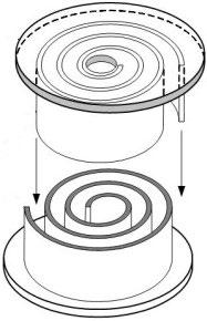
Scroll. The scroll compressor utilizes an oscillating spiral that fits inside a mating fixed spiral or scroll. The orbiting movement of the oscillating spiral creates a flow path that progressively moves from the inlet to the outlet. The precise shape and fit of the two scrolls provides a tight seal without actual metal-to-metal contact and does not require lubrication. The result is a continuous discharge of oil-free air with no pulsations and very low noise. Currently they are limited to 3.75 kW (5 hp).
Centrifugal. Centrifugal compressors are usually used in large horsepower applications, typically above 300 hp. The centrifugal compressor is a nonpositive displacement compressor technically defined as a dynamic compressor. The air is accelerated and compressed as a result of impacting the rotating vanes or impellers. Stationary guide vanes are used to direct the airflow within the compressor. Multi-stage compressors may be inline on a single shaft with intercoolers located between the stages, or integrally geared consisting of a set of separate impellers and housings connected by a common drive gear. Performance of the centrifugal compressor is significantly affected by the discharge pressure and the rotational speed of the compressor. •
1. Which of the following is the preferred location for the compressor inlet?
a. Inside the compressor room.
b. Inside the building close to the main demand location.
c. Outdoors at least 6 ft. (2 m) off the ground.
d. Outdoors close to a wall and an adjacent corner.
e. Indoors under a stairwell.
2. Which compressor type is defined as a dynamic compressor?
a. Centrifugal.

b. Reciprocating piston.
c. Rotary screw.

d. Vane.
e. Lobe.
See page 34 for the solution.
Lubriplate’s complete line of ultra high-performance, hydraulic fluids has been designed to provide a wide range of benefits including: extended fluid change intervals, cooler operating temperatures, reduced friction and reduced downtime. Products include...
•High-Performance, 100% Synthetic, Polyalphaolefin (PAO)-Based Fluids.
•Provides extended drain inter vals and excellent compatibility with seals.
• Available in ISO Viscosity Grades 32, 46 and 68.
•Premium-Quality, Petroleum-Based Hydraulic Oils (ISO Grades 32-100).
• Anti-wear fortified to protect hydraulic system components.
•High aniline points ensure long seal life with fewer leaks.
•NSF H1 Registered and NSF ISO 21469 Certified - Food Machinery Grade.
•High Performance, 100% Synthetic Food Machinery Grade Fluids.
• Available in ISO Viscosity Grades 7, 15, 22, 32, 46 and 68.
•Fortified with Lubriplate’s proprietar y anti-wear additive
•High-Performance, FM Approved, Fire Resistant Hydraulic Fluid.
•NSF H1 Registered and NSF ISO 21469 Certified - Food Machinery Grade.
•ECO-Friendly, Readily Biodegradable (OECD 301F).
•Fortified with Lubriplate’s proprietar y anti-wear additive .
•Hea vy-Duty, High-Performance, Extended Life, Hydraulic Fluids.
•ECO-Friendly - Free of zinc or silicone compounds.
•Provides long ser vice life and extended fluid change intervals.
• Vegetable-Based Oils for use in environmentally sensitive applications.

•ECO-Friendly - Ultimately Biodegradable (Pw1).
•Zinc-free additives provide exceptional anti-wear and anti-rust protection.

•For equipment operating in environmentally sensitive locations.

•Zinc-free and non-toxic to aqua tic life.
•Exceeds U.S. EPA LC50 and US Fish and Wildlife requirements.
•Meets or exceeds the requirements of most hydraulic equipment

• Advanced Synthetic Polyalkylene Glycol (PAG)-based hydraulic fluids.

•Designed for environmentally sensitive industrial and marine applications.

• Meets U.S. EPA Vessel General Permit (VGP) Requirements. Readily biodegradable.
•Does not leave a sheen on the water.
To learn more visit us at: www.lubriplate.com

Here is the solution to Figure It Out on page 5.
» WHEN REPLACING THE electric motor, the company did not notice that the old motor had a 1.2 service factor, which was enough pull-out power. The new motor, however, had a 1.0 service factor and a lower pull-out power. Adding a solenoid unloading relief valve reduced the motor’s start-up load.
The correct answers to Test Your Skills on page 32 are 1-c and 2-a.
www.flangelock.com

The FlangeLock™ Tool is the ultimate contamination control tool for protecting your hydraulic systems. It allows for the simple sealing of open SAE code 61, 62 & CAT-Style hydraulic flanges without tools. Constructed from lightweight aluminum. Easy on, easy off. Offers a leakproof solution to hydraulic system and environmental cleanliness. FlangeLock™ Tools stop the mess!
www.laman.com
La-Man Corporation is a leading manufacturer of compressed air filtration products. With over 30 years of experience, we truly understand the importance of protecting valuable machinery, tools, and finished products from dirty, wet, contaminated air. La-Man’s line of products include the patented Extractor Dryer, .01 micron filter, as well as, LA-MAN-Air Breathing Systems™, SuperStar™ Membrane Dryers, and the Refrigerated Extractor/Dryer.


www.ohfab.com

Hydraulic filtration manufacturers, distributors and end-users have relied on OFCO’s flexibility, product quality and outstanding customer service. Our Central-Ohio manufacturing facility and stable workforce deliver solutions that consistently meet critical specifications and exceed customer expectations.


Have a Purchase Order? Please email to sales@flangelock.com or fax to 203-622-1238
Have a Purchase Order? Please email to sales@flangelock.com or fax to 203-622-1238

PO BOX 328 • Mazeppa, MN 55956
800-348-2463
111 North 14th Street PO Box 218 Coshocton, OH 43812
Phone: 888-354-0291
Fax: 740-622-3307
info@ohfab.com
Precise, linear pressure control within a closed-loop system with ultra high resolution and repeatability.
Clippard’s Cordis is a revolutionary microcontroller primed for escape velocity from a proportional control market. Built with the highest quality Clippard EVP and DVP proportional valves at its heart, the Cordis is designed to outperform the competition in every way. With unparalleled performance and flexibility not possible with current analog proportional controllers, the Cordis makes everything from calibration to sensor variety acceptance to future development opportunities more accessible and less complicated. The future of proportional pressure control has arrived, and it’s digital. Made in the USA.
For further information on the Cordis Pressure Controls or any of Clippard’s line of electronic and pneumatic valves, visit www.clippard.com. Proudly made in the USA.


www.orbitalmotors.net


Hydraulex Genuine Metaris® Orbital Motors are your best low speed high torque motor option in an economical and compact design. The motors are engineered with Roller-Star technology, come in a range of displacements and we offer multiple flange options including wheel mount. You’ll find that our motors are a perfect fit, form and function replacement for common OEM motors in the market today, such as Eaton®/CharLynn®, Danfoss®, Parker® and White®.
www.texcelhydraulics.com


At Texcel, our cutting-edge line of hydraulic hose and fittings is not just a product division. It’s a promise of superior service, quality, technical support and availability. We’ve built our company on impeccable customer service. Let us know how we can make a difference for your business.

www.youngpowertech.com

Young Powertech Inc. is a manufacturer and distributor of complete lines of Mechanical and Hydraulic components. Our strength is delivery of solutions packages to fit most applications using Gear reducers, Helical Rotary Actuators, Radial, Axial, Bent Axis motors and Piston pumps and Gear pumps, Wheel and Track Drives, and complete Electric Drives Systems for mobile equipment. With decades of experience and most advance production in suppliers' factories, Young Powertech delivers more solutions than most.
Visit our website for more information (www.orbitalmotors.net), give us a call (1-800-323-8416), or email us at seattlesales@hydraulex.com
4444 Homestead Road • Houston, Texas 77028 (800) 231-7116 • sales@texcelrubber.com
Visit our website for more information.


P10V45
• Variable Volume Open Loop

• 21 GPM at 1800 RPM
• 4000 PSI Max Continuous
• 5000 PSI Max Intermittent
• 3100 RPM Max
• *Direct Mount To Trans.
• Short Lead Times – Days NOT months
• Mobile Design – Direct Mount PTO
• Special Applications – Torque Controls, Thru Drives, Instant Configuration Changes


DeltaˆQ LTD. 14233 West Road Houston, TX 77041 800-650-3110 info@deltaq.com www.deltaq.com

FluiDyne carries a complete line of A4V piston pumps that are available in displacement of: 40, 71, 125, 180, 250. Our units are used in many different applications: agriculture, forestry machinery, construction, on-highway, commercial vehicles, offshore, marine, wind/ocean energy, automotive and more.
Controls include: DR, DRG, FR, FRG, DFR, and LR2. They are available in SAE or metric. The versatile A4V units carry the industry leading 18 month warranty. Units are fully tested, documented and guaranteed to perform 100% to the original manufacturer’s specification.
Call, email, chat…we’re ready to help!
586.296.7200
• sales@fluidynefp.com
www.fluidynefp.com
Ideal for use with sensitive or corrosive media, this line is an excellent alternative to traditional mechanical valves when media contamination is a concern, as they interact with tubing, PTFE or PEEK, and never touch the material being dispensed! Many features include low power consumption, superior design, low dead volume, high cycle life, fast response and more. Many styles and options available. Proudly made in the USA. View more information and White Papers.
www.clippard.com

The patented AdaflangeTM U61 4- bolt flange adapters provide compact and leak resistant flange connections. ‘Jump Size’ JIC adapters are available in most sizes to closely match adapter flow porting with the mating flange port. Select reducing JIC adapter sizes are also available as standard. Very compact manifold and component porting can be made with simple drill and tap operations, eliminating the need for cavity form tools. They are an ideal solution to retain Code 61 sandwiched flange type connectors and valves.
adaconn®
Blue Bell, Pennsylvania USA
www.adaconn.com
215.643.1900

We're hydraulic filter experts. We've been doing it for over 30 years. We're very competitive and happy to serve your needs. If you need hydraulic filter application help, we know the right questions, and we can give you the right answers.

J/T Hydraulics & Service Co. Inc.
1601 W. 25th Street • Houston, TX 77008
Local: 713.984.9727 • Toll Free: 800.591.8280
Fax: 713.861.2250 • www.jthydraulics.com
Wilkes and McLean manufactures an In Line Noise and Shock Suppressor for hydraulics and is a stocking distributor of Nacol Accumulators. Our suppressors eliminate pulsations, which greatly reduces noise and vibration from applications from a few gallons up to 200 gallons. We stock all of our suppressor sizes as well as Nacol Accumulators and parts from 1/5 of a pint up to 15 gallons, in our Schaumburg, Illinois facility.
877.534.6445 | info@wilkesandmclean.com www.wilkesandmclean.com

Keep your oil clean and dry with Xtract Filter Carts from Lubrication Engineers. These portable filtration systems make it easy to pull oil samples, clean the oil, and maintain oil cleanliness in multiple applications using the same fluid. They enable you to both screen oil to remove large particulates and clean oil to remove small particulates.

www.lelubricants.com


info@le-inc.com 800-537-7683
The Inserta® Products’ ic (inline control) OptimizerTM valve is available in relief functions with free reverse flow as standard. Optional pilot functions including external drain, remote control, vented, and electro-proportional are available.

These flange mounted valves have favorable pressure override, overshoot, and reverse flow pressure drop characteristics. They ship complete. There are no additional valve bodies to purchase, or cavities to machine. Inlet and outlet flow paths share the same axis. They may be considered as advantageous alternatives over standard hydraulic cartridge or 2/2 slip-in logic elements in many applications


The ic OptimizerTM metallic components are made from steel and ductile iron. Critical internal elements are hardened for long life. The valve has a nominal flow rating of 40 gpm and a maximum working pressure of 5000 psi.


MOCAP manufactures an extensive range of protective closures to guard pipes, hoses, and hydraulic fittings from dirt, moisture, and damage to help maintain equipment reliability. Included are a variety of sizes and styles of Threaded and Non-Threaded plastic Caps and Plugs for Metric, NPT, BSP, JIC and SAE Threaded Connections, Ports and Fittings. These are in addition to MOCAP’s already extensive lines of low-cost Caps, Plugs, Grips, Netting, Tubing and Tapes for general Product Protection, Finishing and Masking.


All of our stocked items are ready for immediate shipment and available in Box, Mini-Pack and Micro-Pack quantities. Free Samples are always available for testing purposes.
sales@mocap.com
www.mocap.com
Inserta® Products
Blue Bell, Pennsylvania USA
www.inserta.com

Don’t Compromise – that hydraulic flange you want maybe at MAIN
MAIN stocks 10,000+ hydraulic flanges and manufactures components in 4-7 days in the USA. SAE J518 Code 61 and J518 Code 62, JIS, DIN, ISO 6162, ISO 6164, and specials with socket-weld, butt-weld, ORB, BSPP, etc.; all geometries, flange heads, flange adapters; in carbon, stainless, cupronickel, ductile, aluminum, etc. Sixty years’ experience plus SAE and ISO technical committee experience.


MaIN Manufacturing Products, Inc.
800.521.7918
https://mainmanufacturing.com/block-categories

Go ahead. Push me. Ordinary heavy duty not heavy enough?
Heavy-Duty Mill Cylinders for:
• Induction-Hardened, Chrome-Plated Rods
• Heavy Wall Tubing
• Replaceable Glands & Retainer Rings
• High-Load Piston Design
Think indestructible and call yates. www.yatesind.com
yates Industries (HQ)
586.778.7680
yates Cylinders alabama 256.351.8081
yates Cylinders Georgia
678.355.2240
yates Cylinders Ohio 513.217.6777

Ogura electromagnetic clutches provide a quick and easy engagement of a hydraulic pump, winch drives or other marine components. Available torque range is 100 pound feet to 1500 pound feet with single-face friction designs. Multiple disk units can generate torques over 8,000 pound feet. Large bearings, e-coating and a single piece bi-directional spring provide durability in harsh environments.
Watch our video on how they work: https://ogura-clutch.com/video-mobile.php

Ogura produces a wide variety of electric clutches for mobile applications. These clutches provide simple on/off operation for a variety of pumps. Remotely engaging the pump through the clutch reduces drag on engine start-up, increases pump-life and allows multiple pumps to be used off one engine. Various belt types as well as pump shafts can be accommodated. Watch our video on how they work:
https://ogura-clutch.com/video-mobile.php
Ogura Industrial Corp.
100 Randolph Road • Somerset, New Jersey 08873
Phone: 732-271-7361 • Fax: 732-271-7580
www.ogura-clutch.com • info@ogura-clutch.com
Ogura Industrial Corp.


100 Randolph Road • Somerset, New Jersey 08873
Phone: 732-271-7361 • Fax: 732-271-7580
www.ogura-clutch.com • info@ogura-clutch.com



FILL OUT THIS Ca RD COMPLETELy, DETaCH, a ND M a IL IT TO STa RT yOUR SUBSCRIPTION M a IL TO: PO BOX 293142 • KETTERING OH 45429 YOU CAN ALSO SUBSCRIBE ONLINE AT WWW.FLUIDPOWERJOURN a L.COM.
YES! Please start/continue my complimentary subscription to the Fluid Power Journal 02 NO. Not interested.
Check here if you would like to keep your name, address, phone and fax numbers confidential, and not released to third parties The address above is my:
Address Which edition would you like to receive?
Digital
Both (View a sample of our PAPERLESS digital edition at www.fluidpowerjournal.com)
1. Do you specify, select or influence the purchase of components & systems, on new or existing machinery?
If yes, which technologies? (check all that apply)
2. What is your primary job title? (check only one)
Secretary, Treasury, General Manager, Owner, Business Manager, Director, etc.
MY COMPANY SHOULD BE ADVERTISING IN OR SUBMIT AN ARTICLE TO THE FLUID POWER JOURNAL.
PLEASE CONTACT THIS PERSON:
NAME:
TITLE: PHONE:

We offer high-quality hydraulic hoses, fittings, and accessories with unmatched customer service to keep your business Ahead Of The Curve.
Rely on Texcel’s experienced and knowledgeable team for sales, technical support, customer service, and more.
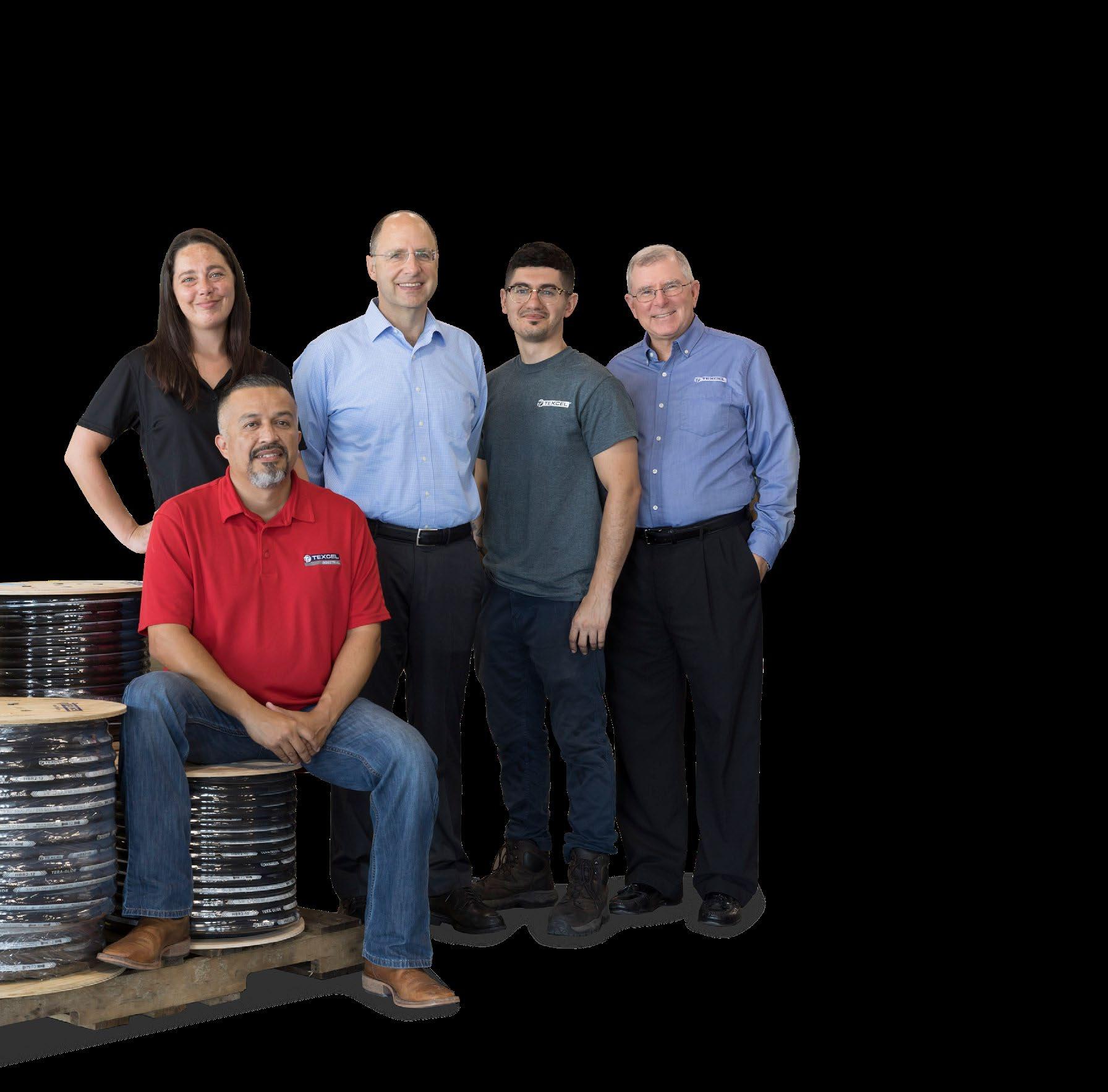
Our broad range of high-performing hydraulic hoses and fittings are designed to exceed your toughest applications.


Explore our U.S. hydraulic inventory, and buy everything you need on one Purchase Order with a 99.9% error-free rating.
