12 minute read
A tale of the sea


by Marco Cattalini
AMPP Italy Chapter Chairman and Technical Manager at CorE srl marco.cattalini@coreconsultancy.it
A note on subsea pipelines cathodic protection design
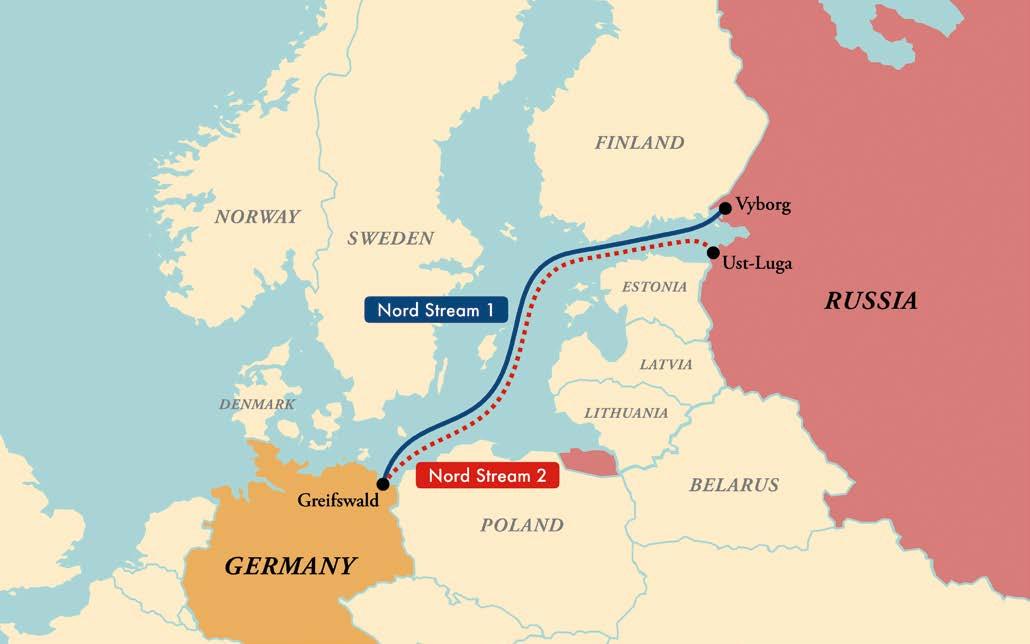
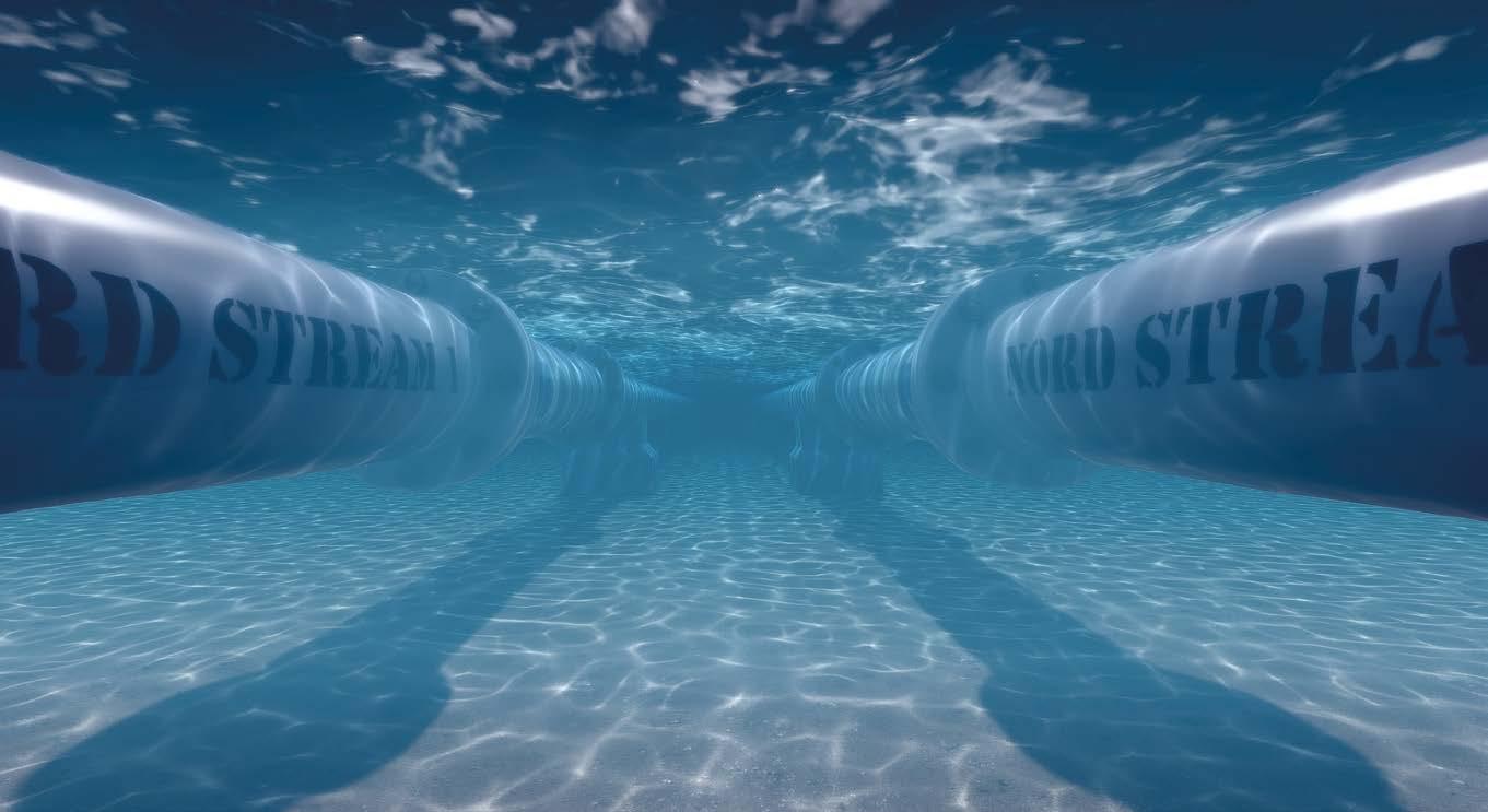
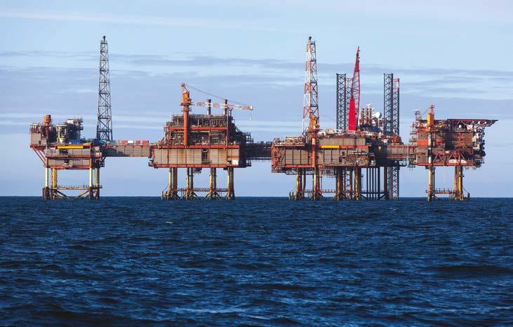
At the end of September 2022, some devices, planted and detonated probably with the help of subsea drones, damaged and made inoperable the two lines of the North Stream Pipeline. An act of sabotage whose perpetrators will probably remain forever unknown in this difficult historical period marked by pandemic, war, and energy crisis. The construction of that undersea pipeline had been the result of a technical and engineering effort in which Italy had been at the forefront both on the design and engineering side with the extraordinary work of Snamprogetti and on the construction side with the commitment and operational capabilities of Saipem; a work of which we should have been justly proud.
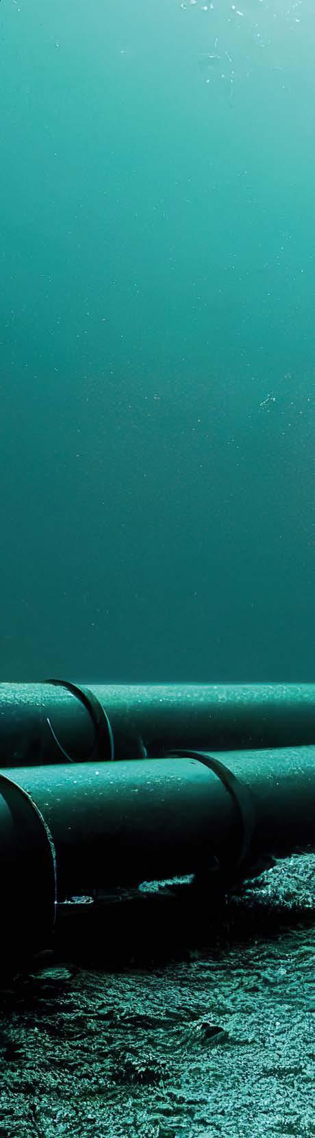
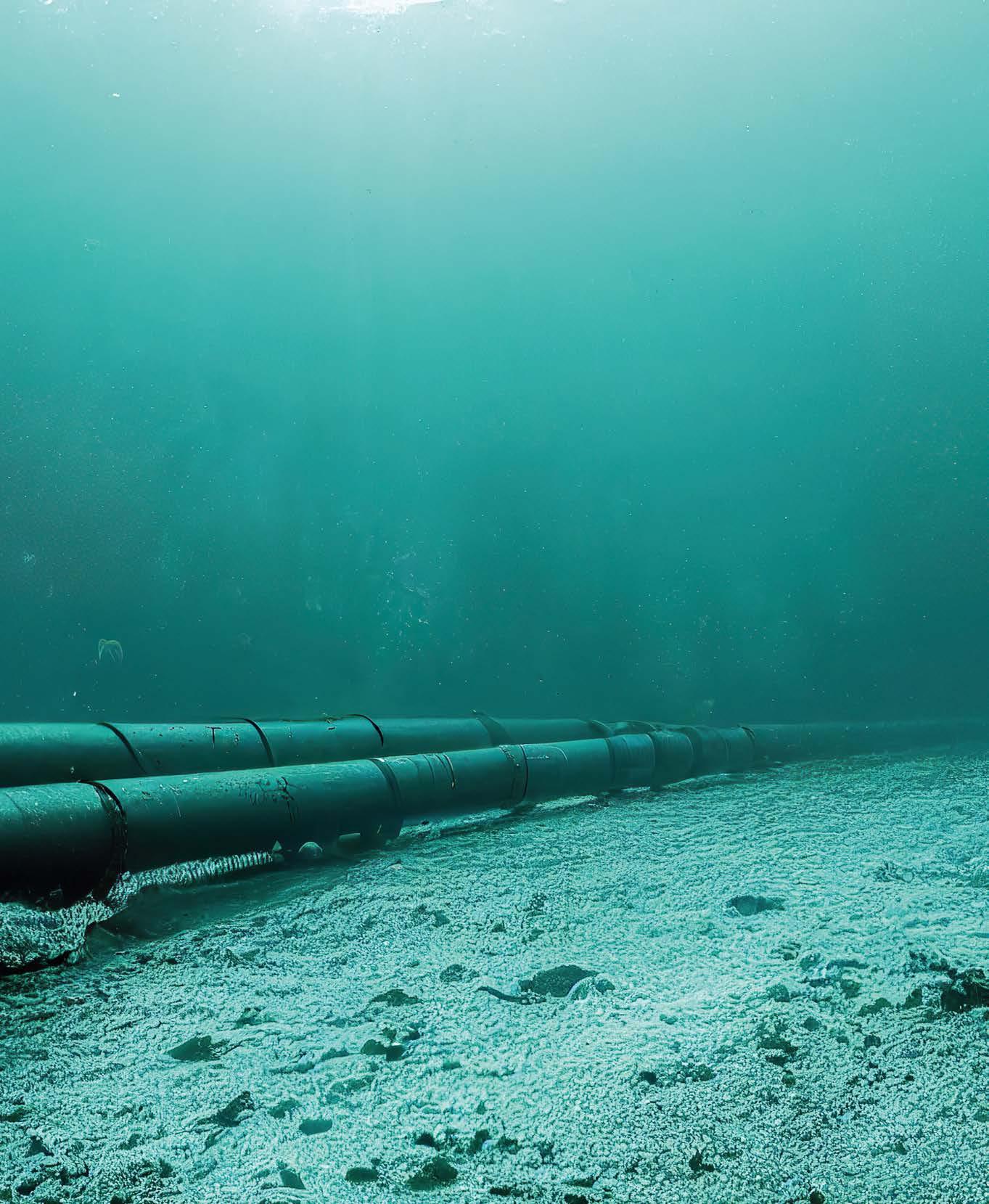
Two 1200 km long 48” diameter lines laid on the bottom of the Baltic Sea. A cyclopean project with a focus on environmental impact that had united distant countries in the name of common and mutual interests. Those pipelines are now out of service, even though they had actually been designed to last with an estimated operational life longer than half a century and, as is always the case with this type of infrastructure, their integrity against corrosion had been entrusted to the combined action of coatings and cathodic protection. In this page, I would like to analyze the approach to a typical design of a submarine cathodic protection systems, may be only as a nostalgic tribute to those pipelines destroyed with explosive charges that, many years ago, were the subject of one of the most important projects that I personally had the possibility to work at.
Like a compass on the high seas
Sailing on the sea of cathodic protection engineering we will find a compass in international standards and regulations. When approaching the design of a cathodic protection system for a subsea pipeline, it will be necessary to take into account, both as a general design philosophy and in relation to the choice of calculation method, specific regulatory and technical references that guide the process.
Subsea pipelines are managed by large companies in the Oil & Gas sector (ENI, TOTAL, EXXON...) or by consortia created specifically for the project itself and, often, companies of this size have an internal regulatory system that regulates the design and management of their assets. It is therefore necessary to refer to corporate specifications. In other cases, however, the project will be subject to the relevant international standards such as: ISO
15589-2: “Petroleum, petrochemical and natural gas industries
- Cathodic protection of pipeline transportation systems - Part 2: Offshore pipelines” or DNV-RP-F103 “Cathodic protection of submarine pipelines Recommended practice.”
Organizing our galley
In order to finalize the cathodic protection design, it will be necessary to collect a complete set of input data that will allow us to evaluate in details a correct protection current requirement and the best way to achieve it.
To do this we will need to find or assume several different parameters related to different aspects of our design such as:
Environment
Pipeline physical and geometrical characteristics
Laying criteria
Operating conditions.
Starting from environmental characteristics we have to include in our input data salinity and more directly the electrical resistivity of seawater and sediment in the laying area.
Average water temperatures at the laying depth and at sea surface, affect both the delivery capacity of sacrificial anodes by directly modifying their resistance, and the aggressiveness of the electrolyte, which could instead affect the amount of current needed for line protection.
Laying depth, on the other hand, directly affects the concentration of dissolved oxygen in the seawater and consequently the current required for line protection.
The chemical composition and the presence of specific substances in the water layers at the laying depth also influence the design: areas with particularly low salinities due to freshwater layers related to thawing periods or the presence of H2S in higher or lower concentrations as in the Baltic Sea or the Black Sea may limit the use of certain anode alloys as imposing more stringent protection criteria. Total length of the lines and their diameter are essential starting data for any design.
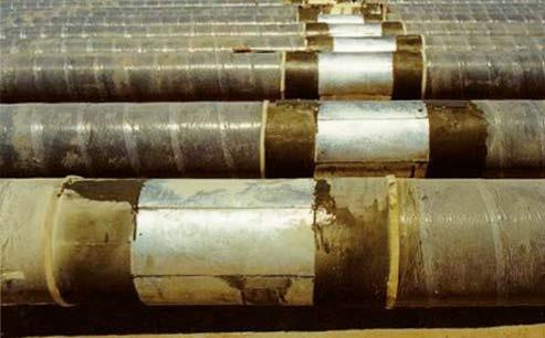
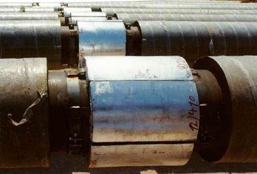
The geometry of the pipeline is not only essential for the correct calculation of the surfaces to be protected, but also dictates the conditions governing the sizing of the galvanic anodes. Apart from shorter pipelines and shore approach sections, in almost all cases, protection is in fact realized by means of sacrificial systems. These are normally based on so-called “bracelet” anodes consisting of two shells that are installed astride the line itself and then electrically connected by cables or steel straps welding. The size of the anodes cannot therefore be separated from the dimensions of the pipeline, which become binding for their design and construction.
The characteristics of the pipeline also include the technical details related to the anticorrosive coating that directly contributes to the assessment of the protection current and the possible concrete coating layer, used both as a weighting of the line to increase its stability on the seabed and as mechanical protection, that can introduce limits to the maximum thickness of the galvanic anodes.
Although most pipelines are made of carbon steel, it is sometimes possible to have to make protection systems for other materials such as stainless steels with significant impacts on the choice of protection criteria, the composition of the anode alloy of the sacrificial anodes, and the presence or absence of special control and current-limiting systems inserted into the electrical connections.The laying of subsea pipelines requires special conditions that often have direct impacts on the design and operation of cathodic protection systems. First, the individual pipe joints, which have a standard length of about 12 m, must be welded together inside the pipe-laying vessel and then lowered into the sea through a complex system of rollers and track tensioners that ensure their stability. The need for the pipelines to pass through rollers and tensioners significantly conditions the maximum thickness and shape of the bracelet anodes installed on the pipeline since these shall not only not be an obstacle to laying operations, but also be installed in such a way they will withstand the impacts and mechanical stresses due to the passage of the line over the transport and control systems.
Geological information on seabed conditions will then be necessary to predict, already at the design stage, what the condition of the pipeline’s burial will be once it has touched the seabed. In fact, it will be necessary to consider whether it is resting on the seabed itself or sunk into the marine sediment; as a matter of fact, the pipeline’s burial conditions will impact the delivery capacity of the anodes as much as the line’s current demand. In particular situations related to stability problems due to particular underwater currents or to the need to provide mechanical protection to the pipelines in fishing areas or in correspondence with underwater crossings with other lines, it may be necessary to proceed with a forced burial of the pipelines through the excavation of underwater trenches or with the technique of “rock dumping,” i.e., covering the line laid on the seabed with rocky material.
Another fundamental information for the cathodic protection system sizing is the temperature of the line. Indeed, this affects both the amount of current required to protect the surface of the line itself and the electrochemical efficiency of the anodes; in fact, the amount of protection current expressed by a given mass of anode alloy is directly related to its operating temperature. At the expense of the anodic reaction underlying the protection process, the electrochemical self-corrosion reactions triggered in the sacrificial alloy become increasingly competitive as the temperature rises. As a consequence, the mass of sacrificial anodes required to protect the pipeline for the expected lifetime increases significantly in relation to the temperature of the section.
It therefore becomes necessary to collect data from a detailed thermal analysis of the line carried out on the basis of the temperature of the transported fluid, the temperature of the seawater, the burying conditions, the conducting and insulating capacities of the steel with which the pipelines are constructed, and the applied coatings.
Let’s go on our journey: the design
Only once the reference standard has been selected and the collection of the necessary design data has been completed, it will then be possible to proceed to the next steps that will lead to the sizing of the system and the final definition of the number, required mass and geometric characteristics of the sacrificial anodes needed to protect the pipeline.
To do this we will need to move one step at a time starting from a sectioning of the entire pipeline in homogeneous sections, evaluating the required protecting current for each of them and finally define the correct amount and distribution of sacrificial anodes necessary to guarantee the required current for the entire project lifetime.
Our starting point will be the analyses of the collected data with the goal of dividing the line into sections that are as homogeneous as possible.
Sections with concrete weight coating (CWC) will be protected by sacrificial anodes with dimensions constrained to the thickness of the concrete itself in order not to interfere with line launching operations. Sections without CWC will instead see “tapered ends bracelet anodes,” also sized for the purpose of facilitating the passage of the anode itself through launching rollers and tensioners.
Based on the burying conditions, the presence or absence of CWC, on the depth and, above all, the temperature profile, a series of pipeline sections that can be protected with sacrificial anodes of a given mass and geometry must be identified. This step is critical and is related to the overall economics of the system. In fact, an anode designed to protect a section at high operating temperature and exposed to seawater could be significantly redundant in mass and delivery capacity for a section sunk into the marine sediment and with lower operating temperatures. In the absence of this preliminary analysis, the risk is to arrive at overall results that would lead to the assumption that a total mass of anode alloy is needed several times more than is actually required with a dramatic increase in purchase and installation costs.
Once the line has been sectioned into homogeneous sections, the current required to protect the line will be calculated for each of them. The calculation process will be indicated by the reference standard selected for the project. Apart from slight differences in the philosophical approach to the calculation, which tend to shift the focus more or less toward the efficiency of the linings or environmental and operating conditions, all standards indicate a similar calculation process. First the total surface area of the pipe section is calculated, then, depending on the type of coatings selected, the percentage of metal surface area directly exposed to the electrolytic environment is estimated. Leaning on the indications contained in the relevant standard, the degradation of the coating over time is then assumed, and the percentage of exposed metal is calculated after a lifetime equal to the expected lifetime of the project itself. Based on the installation depth data and the operating and environmental temperatures, current densities required to protect the structure are then selected. The protective current densities are tabulated in the selected standard for the project and are processed together with the other data to arrive at an “average” total protective current to be considered for the pipeline operating period and a “final” protective current that evaluates, based on the expected life time for the project, the most drastic conditions under which the coating would have lost some of its insulation efficiency and the area of exposed metal would greatly increase.
After calculation of the average total current and the final total current it will then be need to proceed to the evaluation of the anode mass necessary to protect the line for the entire life of the project and the maximum resistance of the single sacrificial anode necessary to guarantee the minimum amount of protection current even under the most severe conditions when both the anodes will be partially consumed and the coating will have lost part of its insulating capacity. This will lead to two different situations with a design that, given the results of the calculations, may be guided by the mass or the minimum current required. We will then see that the two approaches may lead to extremely different choices with respect to the shape, number and distribution of anodes along the line. In the design of a galvanic anode cathodic protection system, for a pipeline that can be up to thousands of kilometers long, an understanding of the parameters that drive the electrochemical reactions involved in the protection process becomes critical.

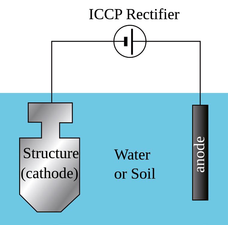
Unlike with an impressed-current system, where the voltage of the delivery system can be increased, normally, up to values of 50 V, the potential difference available for the circulation of the protection current is limited by the characteristics of the anode alloy chosen.
In a sacrificial system, the only available supply voltage will be provided by the electrochemical potential difference between the anode alloy and the metal of the pipeline once the circuit is closed. We cannot consider the free-corrosion potential that the pipeline would exhibit if the cathodic protection system were not present as the potential of the pipeline, but instead we must indicate the potential value that we want the pipeline to assume once protected. For the anode alloy, we will have to go and evaluate, also considering the operating conditions of the anode, the potential of the anode alloy once the anode is connected to the pipeline: what is referred to as the “closed-circuit potential.” In seawater, it is normally not possible to use Cu/CuSO4 (CSE) reference electrodes since such electrodes are sensitive to pollution by chloride ions abundantly present in the water. All values given are therefore referred to an Ag/AgCl (SSC) electrode. The regulatory protection criterion establishes the value to be achieved for a polarization potential for the protected pipeline the limit of 0.8 V SSC for carbon steel pipelines in an aerobic environment. The values change if different metals are considered or if seafloor areas with anaerobic environments that might harbor colonies of sulfate-reducing bacteria (SRB) are considered.
For anodic alloys, on the other hand, closed-circuit potential values are tabulated in the standards; depending on whether one is going from zinc-based or aluminum-based alloys, they change from -1.030 V to -1.050 V SSC. Some standards indicate less electronegative values in case the anodes are found not immersed in seawater, but in marine sediment.
In the best-case scenario, therefore, we will be operating with a potential difference available for the circulation of the protective current of 250 mV. It is therefore clear that, in order to guarantee the amount of current needed to protect the pipeline, it will be essential to design anodes with the lowest possible electrical resistance, and the electrical resistance of the anodes to the electrolyte depends directly on their exposed surface area. Therefore, not only will it be necessary to assess precisely which parts of the anode will actually be in contact with the seawater to ensure uniform consumption, but also the size of the anode once it has been gradually depleted as the design life progresses will have to be considered. Both the initial and final exposed surface areas will then have to be evaluated in order to obtain the electrical resistances under the two conditions. Knowing both the resistance of the individual anode and the available potential difference, it will be a simple matter to use Ohm’s law to calculate the maximum current that can be delivered by each of the anodes and thus define their minimum number based on the total current demand.
A treasure hunt
Now that we know shape and mass of our anodes, we need to find them on the market and it will be necessary to consider all peculiarities related to the fabrication, verification, and installation of bracelet anodes. The fabrication of such anodes involves several practical restrictions; in addition to the problems associated with the homogeneous casting of often large parts, specific skills will be required to make the inserts (welding), the surface preparation by sandblasting and painting, and all stages of construction will be accompanied by extremely precise quality controls. The conditions for the design and production of anodes are regulated by various international reference standards such as: DNV RPB401; DNV RP F103; EN ISO 155889-2; NACE RP 0492 as well as the specific proprietary regulations of the various companies that will operate the subsea pipeline. The design of the anode will first have to ensure that the available mass and surface area meet the requirements dictated by the demand for cathodic current over time, but will at the same time have to reconcile these requirements with the feasibility conditions of the anode. But that’s another story… ‹
The most important industry events at your fingertips myFAIR is a free web app that can be accessed from both desktop and mobile devices, which allows you to stay up-to-date with the leading events of the surface treatment sector.