
8 minute read
INSPECTION LOGBOOK


Coating Inspections - Inspection of Steel Surface Preparation, Part 6
Massimo Cornago
NACE International Certified Coating Inspector, NACE CIP PEER Reviewer cornago@ipcm.it
As mentioned in the previous article, we will now discuss the surface profile testing methods used to check that a specified surface profile has been attained. In fact, when protective coatings need to be applied on structures, it is important that their surfaces are clean and dry in order to prevent premature failure of the coating itself and guarantee a long service life. In many situations (for both new build and repair of structures), blast cleaning of surfaces is required to remove any contamination and create an anchor pattern to enhance the adhesion of the coating system to the substrate. Profile measurement is key to comply with specifications, but also to ensure that the blast cleaning process is controlled and it does not produce inadequate or excessive profile heights. Two ASTM standards dealing with surface profile assessment, namely “D 4417-Standard Test Methods for Field Measurement of Surface Profile of Blast Cleaned Steel” and “D 7127-Standard Test Method for Measurement of Surface Roughness of Abrasive Blast Cleaned Metal
Surfaces Using a Portable Stylus Instrument”, are normally used. In this article, we will discuss the standard ASTM D 4417, describing three methods for assessing profiled surfaces, while taking the appropriate international standards, i.e. NACE, SSPC, and ISO, into consideration.
Testing for surface preparation (ASTM D 4417)
The inspector should verify that the specified surface profile has been attained, based on the definition of surface profile as the distance (height) from the peaks to the valleys (or the roughness) created by abrasive blast cleaning. Increasing the surface profile effectively increases the surface area of steel, promoting good coating adhesion. Too shallow a surface profile may result in premature coating failure due to lack of adhesion, which can result in peeling, blistering, or delamination. Too high a profile may have peaks that are inadequately covered, resulting in rust rashing or rust spots. Surface profile tests should be done daily and every time there is a change in the abrasives, the blasting pressure, or other operating parameters. The three methods normally used in the industry for assessing surface profiles, described in ASTM D 4417 in order of preference, are as follows: • Comparators (Method A) • Profile depth gage (Method B). • Replica tape (Method C).
Profile comparator (Method A)
Method A is commonly referred to as the Surface Comparator and the most commonly used version is the “ISO Surface Comparator”, which meets the requirements of ISO 8503 – 1. There are two versions of this comparator, one for grit blasted surfaces and one for shot blasted surfaces. The difference can be seen in the shape of the profile, the grit profile is angular and the shot profile is more rounded. Each ISO comparator has four segments representing grades of profile depth. The comparator is used by either visual or tactile comparison with the surface to be inspected and the two segments that bracket the test surface are determined. Other similar comparators include the Keene-Tator Surface Comparator, the Rubert Surface Comparator, and the Rugotest Surface Comparator. These are less commonly used since the ISO test method was published, but as paint specifications have a relatively long life they are still used.
The correct procedure is as follows: 1. Select the comparator disc prepared for the type of abrasive used (i.e. grit/slag, shot, or sand) and place it directly on the blast cleaned steel surface. 2. Compare the test area visually using a 5X magnifier to best match one of the standard profiles. The magnifier should be in focus with both the blasted steel and the disc. Matching may also be done visually without magnification. It is not advisable to do the matching by touch, in order to avoid any surface contamination. If the profile falls between two standard profiles, indicate a profile range between these two profiles (i.e. 50-76 micrometres or 2.0-3.0 mils). 3. Determine the profile at sufficient locations, as indicated in the project specification or as agreed upon by the interested parties, in order to characterise the surface, making three assessments at each location.
Five grades may be recorded: 1. Finer-than-Fine Grade – any profile assessed as being lower than the limit for Fine 2. Fine Grade – profiles equal to segment 1 and up to, but excluding, segment 2 3. Medium Grade – profiles equal to segment 2 and up to, but excluding, segment 3 4. Coarse Grade – profiles equal to segment 3 and up to, but excluding, segment 4 5. Coarser-than-Coarse Grade – any profile assessed as being greater than the upper limit for Coarse.
The calibration of a comparator shall be carried out every six months (see ISO 8503/1). Comparators require careful handling and if any surface wear is observed, re-calibration shall be carried out before further use. As a guide, comparators in daily use may require recalibrated every three months. In all cases of dispute, re-calibration should be carried out prior to re-assessment of the test surface. The accuracy, precision, and repeatability of the test depend greatly on the individual administering the test.
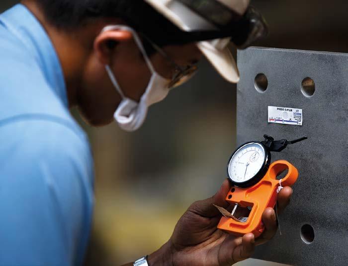
Profile depth gage (Method B)
Method B describes the dial gauge depth micrometre, also known as the Surface Profile Gauge. A profile depth gage (or depth micrometre) consists of a dial gage and a stylus (pointer) that protrudes from the base of the gage. The base of the gage rests on profile peaks, while the stylus protrudes into the valleys of the blasted steel surface. The profile is therefore determined based on the relative position of the tip of the stylus and the base of the gage. Several readings must be taken to ensure that the stylus rests on the tops or sides of the peaks rather than fully penetrating the valleys.
The correct procedure is as follows: 1. Hold the gage by the base and press it down onto the blasted steel surface until a reading appears on the dial. 2. Make several measurements at several locations and average those taken at each location. Do not slide the gage along the surface, as this will damage the tip of the stylus.
3. Calibration is done placing the gage on a smooth glass plate and adjusting the outer ring of the dial, if necessary, to read zero, in compliance with the National Physical Laboratory procedure in the UK or the NIST one in the US; the certificate also has this traceability.
Replica tape (Method C)
The replica tape is the most commonly used method for measuring the surface profile of prepared steel. It consists of a layer of deformable plastic bonded to a polyester backing. The deformable side of the tape is rubbed onto the blast-cleaned surface with a rigid swizzle stick to produce a reverse replica of the profile (mirror image of the real profile). The tape profile is inserted between the anvils of a spring micrometre and a measurement of the surface profile or roughness is obtained. The tape consists of a 51-micrometre (2.0-mil) thick film of noncompressible Mylar, which serves as a backing for an emulsion containing microscopic bubbles. The tapes can be stored as permanent records of profile heights.
The correct procedure is as follows: 1. Select a piece of tape representing the desired profile range, between COARSE (20-50 micrometres or 0.8-2 mils) and X-COARSE (38-110 micrometres or 1.5-4.5 mils). It may be possible to measure up to 150 micrometres (6 mils) using X-COARSE tape. Remove its paper backing and place it on the blast cleaning steel surface, with the adhesive side downwards. 2. Holding the tape firmly in place, rub the circular portion with a burnishing tool until the non-deformable Mylar backing on the tape turns uniformly grey. 3. Remove the tape and measure its thickness within the circle using a spring micrometre. Then, subtract the thickness (50 micrometres or 2 mils) of the Mylar backing to obtain the actual profile measure. 4. Measure the profile at sufficient locations, as indicated in the specifications or as agreed upon by the interested parties, to characterise the surface profile. The only verification that can be undertaken for the replica tape is on the dial gauge used to measure the tape after the replica has been formed. The dial gauge readings can be checked using the same measured thickness foils or shims that are provided for coating thickness gages using values in the range 50 to 250 μm. Foils of this type can be supplied with a calibration certificate and the measurements are traceable to NIST or other National Standards such as the National Physical Laboratory in the UK. As part of the verification process, it is essential to ensure that the correct grade of replica tape is used to measure the profile in question. Each tape has an upper and lower limit for the range of profile height. The Replica Tape requires the replica to be taken and then measured, and the burnishing can take several seconds. However, an experienced inspector can get values within half a minute, and the replica tape can be stored in an inspector’s notebook as a permanent record of the test.
After surface preparation, the inspector may again be required to verify that the surface is free of any contamination, particularly of soluble salts, grease/oil, and dust. • Soluble salts: this test is normally performed after the steel has been prepared by blast cleaning; however, if a long time interval occurs between the application of one coating layer and another (i.e. full top coating shop-applied primer), it may be advisable to check for contamination on the existing coating to be overcoated. • Grease/oil: after surface preparation, the inspector may again be required to verify that the surface is free of grease and oil contamination, to reduce © Adobe Stock any coating adhesion. The prepared surfaces must be completely free of grease and oil. • Dust: abrasive blasting and other media at the jobsite can leave dust on cleaned surfaces. Dust collected on cleaned surfaces can interfere with coating adhesion, so the prepared surfaces must be completely free of dust. In the next article, we will further discuss the testing methods for surface contamination after surface preparation. ‹


