5 minute read
Wall blocks used for retaining systems and stormwater attenuation
Wall blocks used for retaining systems and
STORMWATER ATTENUATION
Retaining block walls have been used for the construction of extensive retaining systems and erosion control measures at one of the grassroots sites at Lanseria Corporate Estate, an environmentally sensitive industrial park adjacent to Gauteng’s Lanseria International Airport. Dubbed “One on 75” and developed by Erf 844 Joint Venture, the project entails the construction of a plastic mouldings factory which is due for completion in October 2021.
One of the estate’s regulations is that all developments must comply with an approved JRA form of stormwater attenuation to prevent downstream flooding, erosion and pollution. In addition to two retaining systems, three attenuation ponds were built for the “One on 75” project using retaining wall blocks supplied by CMA member, MVA Bricks.
Abbeydale Building & Civils is the development’s principal building contractor and Jodan Construction the project’s bulk earthworks contractor. Retaining wall specialist, PG Con, constructed the retaining block systems, which included the retaining systems for the attenuation ponds. Civil design, stormwater attenuation and site planning were completed by Tribid Projects and the design of both the building platform block walls and the attenuation pond block walls was handled by Crossman Pape & Associates, in compliance with the design and construction contract.
Attenuation ponds
Over 6 500m² MVA-7 concrete retaining wall blocks were used to construct the attenuation ponds and the retaining systems. Two large ponds were built on the western perimeter of the site and a third subsidiary pond was sunk at the northeastern corner.
“Although the attenuation ponds are unusually large, their footprint in relation to the overall size of the site is relatively small,” says James Croswell of Tribid Projects. “The north-western pond measures 50m x 20m and has 3 000m³ capacity; the south-western pond measures 75m x 15m and has a 2 000m³ detention capacity; and at 40m x 15m, the north-eastern pond has a water detention capacity of 1 500m³. Two further ponds will be built along the property’s eastern boundary when a proposed building extension is unveiled at a future date.
“This is the first time we’ve used concrete retaining block walls exclusively


for building attenuation ponds and to save space, we made the ponds relatively deep. We looked at several building materials to meet our design criteria, but in the end, the MVA-7 block proved the most economical option,” says Croswell.
Balancing act
Croswell explains that all the material for general fill and the selected layer works was sourced on site. “However, we did find some unsuitable material (about 20 000m³) at a depth of 300-400mm which had to be removed. This meant we had to adjust the level of the platform so that the cut-and-fill and the fill behind the block walls balanced and we used a sophisticated software program to do it. Moreover, there wasn’t as much rock on site as we’d anticipated, although there was enough to stabilise the critical areas.”
The retaining system walls and the pond walls were built at 70º. The northern boundary platform wall is a fill wall 260m long, rising from 0,5m in the north-western corner to a height of 9m in the north-eastern corner. The western wall is a cut structure 315m long, rising from 0,5m in the north-western corner to
11,5m in the south-western corner.
Both the pond and the building platform walls were built with the lower half of each in closed-face configuration, using MVA-7 blocks and sliders supplied by MVA Bricks. The top sections were constructed in open-face configuration. Moreover, the cut-and-fill walls and the backfill in the attenuation pond walls were cement-stabilised. Maccaferri’s WG-6 geofabric was used to reinforce the fill material behind each wall at every fifth block course.
Future developments
All the walls were built with 45º wick drains every 1,5m. They discharge into bottom drains and, in walls higher than 4m, into mid-level drains as well. Croswell adds that the ponds were designed for attenuating a 25-year post-development run-off, discharging at the five-year predevelopment outflow.
The ponds have a weir capacity which accommodates a 1:100-year storm event. All the water collected off the building and the concrete platform which surrounds it drains into both western ponds. Lined (Armorflex) channels have been installed along the bottom of the ponds to cater for low flows and an overflow culvert was constructed at +1,5m for draining high outflows from the south-western pond.
The discharge from the south-western pond is routed through the north-western pond before being discharged into a 10 000m³ sub-regional pond via the township’s stormwater system. The northeastern pond drains into an open channel which runs along the township’s eastern boundary. It also discharges into the subregional pond, which is used to distribute greywater to the entire estate, primarily for the flushing of toilets and for watering plants.
“The greywater is partially purified through the removal of hydrocarbons by the vegetation which grows at the bottom of all the attenuation ponds on the estate. Each developed site is allocated a greywater quota at a ratio determined by its catchment area and the water is pumped through a set of solenoid valves. Smaller sites use header tanks for storing the water, whereas two 10 000-litre JoJo tanks will be installed at the ‘One on 75’ site,” says Croswell.


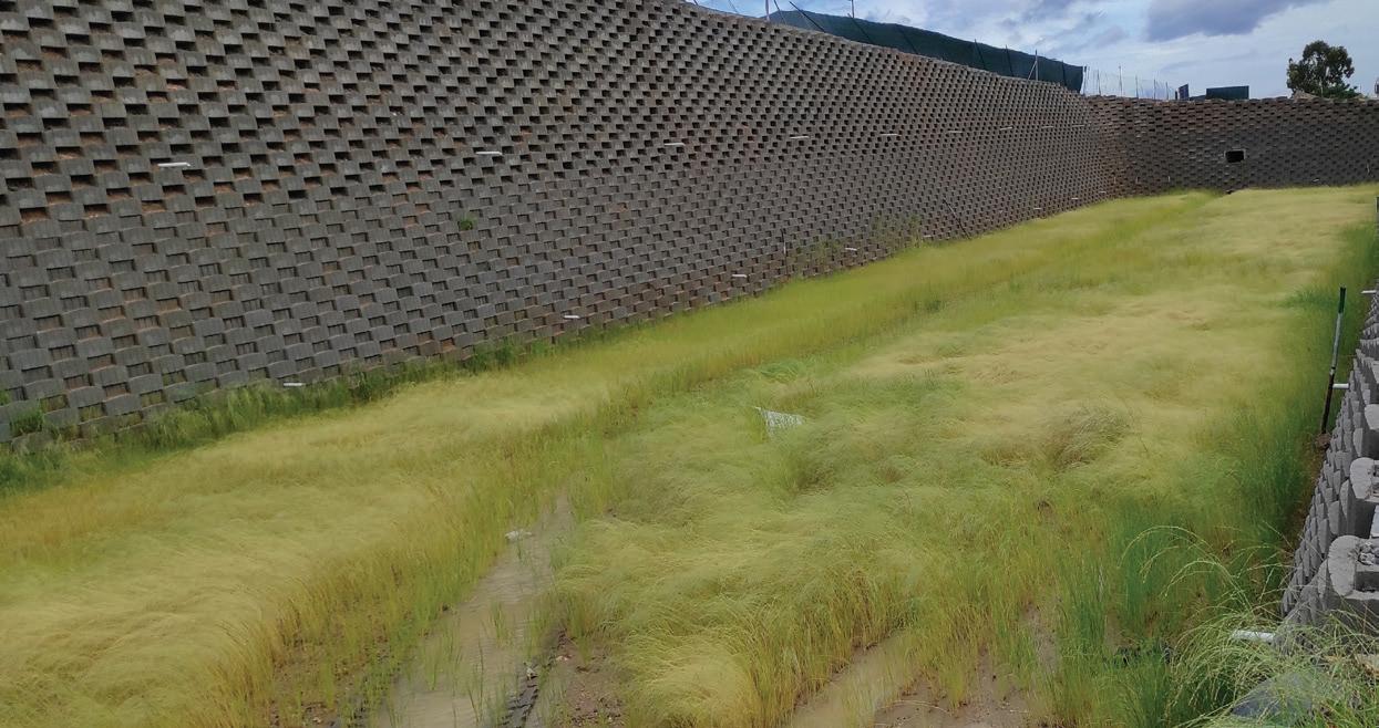
(Top left): The grass-covered bottom of one the attenuation ponds shortly after a severe thunderstorm.
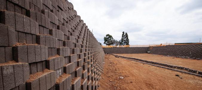
(Far left): A close-up of an attenuation pond closed-face wall which was built using MVA-7 retaining wall blocks and sliders.
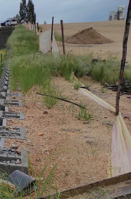
(Left): One of the attenuation ponds under construction.
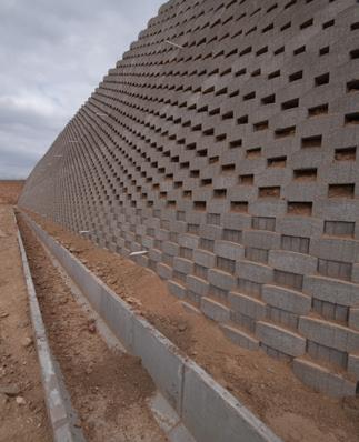
(Above right): A water channel runs adjacent to one of the attenuation walls which was constructed in a closed- and open-face configuration.


