10 minute read
Paarl bridges widened with precast concrete beams


Paarl bridges widened with
PRECAST CONCRETE BEAMS
A project being headed by UDS Africa to upgrade Berg River Boulevard and Oosbosch Street in Paarl was commissioned by the employer, Drakenstein Municipality, in 2013. The first phase, which included the upgrading of Berg River Boulevard from Lady Grey Street to Optenhorst/Oosbosch Streets, was started in 2016 and completed in 2018.
This phase included the construction of the abutments and piers for the subsequent widening of the 100m-long Oosbosch Street bridge over the Berg River. The bridge traverses a railway line some 600m from the Berg River bridge. Both bridges are being widened using precast concrete beams manufactured by Cape Concrete. The bridge-widening project was begun in August 2019 and is due for completion in August 2021.
The bridge-widening forms part of upgrading a section of Oosbosch Street between the Berg River Boulevard and Jan van Riebeeck Street. Members of the bridge-widening professional team include main contractor, Martin & East, AECOM SA, Empa Structures and Mowana Engineers.
Old bridges
Both bridges were first built as beam-andslab structures in the 1960s. The river bridge is now being transformed from two to four traffic lanes, whereas the rail bridge, which was originally built as a narrow four-lane thoroughfare, is being widened on either side to accommodate new pedestrian walkways and allow the full width of the original bridge to be used solely for traffic.
The original river bridge was constructed with post-tensioned beams, building technology which was considered for the current project. However, UDS finally approved the contractor’s proposal for pre-tensioned precast beams as being the more cost-effective and time-efficient option and Cape Concrete was commissioned to cast 20 T-beams, 26m apiece.
The rail-bridge extension required four 10m reinforced concrete beams and balustrades to be cast as single full sections by Cape Concrete. Two of these beam/balustrade units were placed on either side of the bridge. By casting the beams and balustrades as a single unit, no staging was necessary, saving much valuable time. Moreover, the use of precast elements meant that the manufacture of the beams for both bridges, and the precast permanent shuttering for the river bridge, could take place during the early stages of the project and be run concurrently with other construction work.
Time-saving
AECOM SA designed both bridges. AECOM engineer, Jacobus Kritzinger, says that having extended abutments and piers for the river bridge already in place saved further construction time. “In addition, the benefit of several construction activities taking place simultaneously reduced pressure on the programme and yielded savings for the client and all parties involved. In order to achieve uniformity throughout the new river bridge structure, we adopted the same type of cross-section
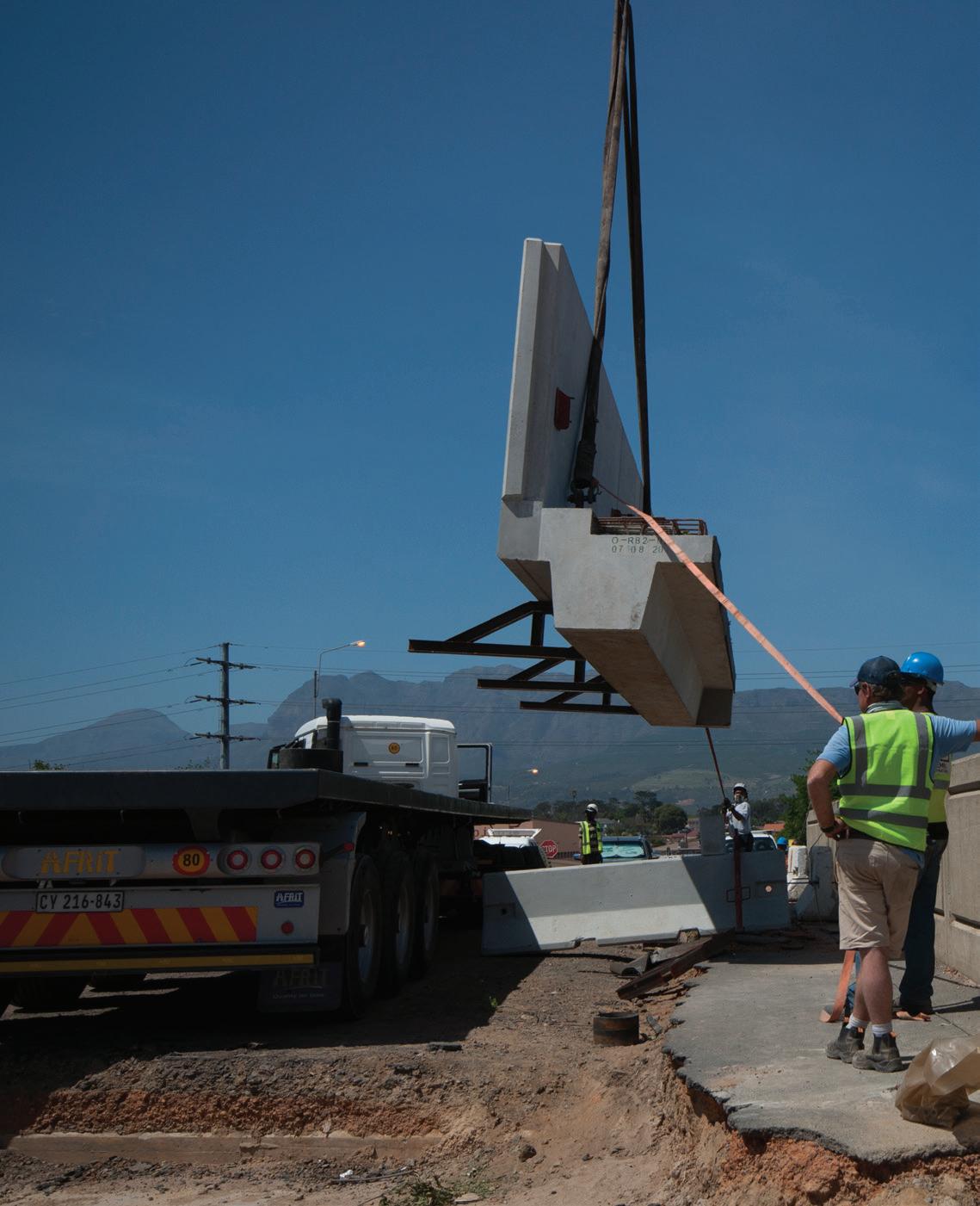
(Left): One of four precast concrete beam/balustrade units being lifted off the truck bed and lowered into position on the rail bridge.
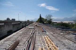
(Above): Elements of the partially constructed river bridge.
profile we found in the original design – but, of course, using pre-tensioned, rather than post-tensioned beams,” says Kritzinger.
“It was essential that the structural behaviour of the new beams mirrored the structural behaviour of the existing post-tensioned beams as closely as possible, because construction tolerances were very tight. This meant we had to model and analyse the deflections and the induced movements of the pre-tensioned beams to match those of the existing beams as much as we could.”
Allowing for creep and shrinkage in this alternative beam design proposed by the contractor entailed some specialist engineering input, which was why consulting engineers, Mowana Engineers, was appointed to design the pre-tensioned concrete beams.
Creeping bridge
Edward Smuts, Mowana Engineers bridge engineering director, says there was evidence that considerable creep had taken place on the bridge over its 50-year lifespan.
“Armed with the concrete and section properties of the old bridge structure, we were able to simulate theoretical deflections in order to match the behaviour of the new beams as closely as possible with the performance of the original beams. Part of this exercise involved calculating instantaneous and long-term creep. Based on these calculations, we compiled a report which was submitted to AECOM in the first instance and, once approved by them, to Cape Concrete,” says Smuts.
Cape Concrete factory manager Johan Nel says that as a result of Mowana’s calculations, some additional detailing was required in casting the river bridge beams and this aspect was handled by Mowana. “We’ve done numerous post-topre-tensioned conversions with Mowana Engineers and they get involved with the pre-stressing and checking procedures.
“The river bridge beams were specified as W40MPa and the rail bridge beams as a W50MPa mix. However, we used the W50 mix for the river bridge beams as well because it also covers ASR durability issues. We’ve used this formula historically on other bridge projects, with very satisfactory results.
“Steam-cured, the road bridge beams

reached the desired de-tensioning strength after 18 hours. However, we only detensioned on the third day because earlier de-tensioning leads to greater hog and deflection issues. It was essential that we controlled the deflection of the beams very carefully so that they matched the camber alignment of the existing bridge beams,” explains Nel.
Work-in-progress
Empa Structures was appointed by Martin & East to handle the actual construction of both bridges. Work on the river bridge involved the installation of bearing pads, beam placement, cross-bracing with insitu cast diaphragm beams and casting a reinforced concrete deck on reinforced concrete permanent shutters. It also involved demolishing the old balustrade above the midpoint of the new bridge structure and replacing it with an in-situ cast safety barrier between the two sets of traffic lanes.
Unlike the river bridge, the abutments and centre pier of the rail bridge had to be extended under extremely constrained conditions. Once this was accomplished, the precast beam/balustrade units were placed on the bearing pads and attached to the existing bridge structure. Work still to be done at the time of writing includes demolishing the two original balustrades, constructing new pavements and resurfacing the road.
José Dos Reis of Empa Structures says the river beams were placed on the bearing pads using two mobile cranes.
(Above): Workers involved with attachment of a precast concrete beam/balustrade unit to the rail bridge.
“Because the bridge has a high mid-point, the abutments and piers were sloped for stormwater drainage. This meant that when the bearing pads were installed, they had to be offset with epoxy to attain a level resting position,” he says.
River beams
“The river beams were cast with bendout bars for attachment to the diaphragm beams. They were also cast with seven 50mm PVC ducts at the point where they crossed the diaphragm beams to enable Y25 continuity rebar to be installed along the full length of the diaphragm beams for additional strength. This required a high level of precision in casting the precast beams because the ducts had to run parallel to the slope of the diaphragm beams.
“Once all the precast beams were placed, we started with the in-situ casting of the diaphragm beams. The river bridge has 28 diaphragm beams at seven beams per span, which resulted in a massive and extremely strong monolithic bridge structure. The main diaphragm beams were installed at each abutment end and above each pier. As each diaphragm beam has six sections, the bridge required 196 diaphragm casts.
“Two of the spans are positioned above the river and we had to comply with very strict environmental conditions; we used long through-ties to support a gangway below the diaphragm beams. As soon as the diaphragm beams in each span were completed, we installed permanent concrete shutters between the precast beams. We’d cast 1 500 on site and some of them needed trimming, because we were working to very tight tolerances. Any gaps of 3mm or more were sealed with multi-bond epoxy. This was done to prevent any grout loss when we poured the deck concrete,” says Dos Reis.
Deck slab
“Once the deck shuttering was in position, we installed the rebar for the deck slab, which took about a week to 10 days to do. We then inserted our level rails and cast the deck to a thickness of 125mm. Each span took 40 cubes of concrete and once the screeding and floating were done, the deck was water-cured for seven days. This process was repeated for each span,” says Dos Reis.
When the old outer balustrade, which was used as a safety barrier during construction, is demolished, an infill beam – which will form the foundation for the median/central traffic barrier – will be cast along the full length of the bridge. The barrier and a new outer balustrade will be cast in-situ, with extensive reinforcing.
Dos Reis says that before the beams could be placed on the rail bridge, a colossal amount of preparation work went into widening the central pier and the abutments. “What made it tricky was that we were working above and under two 3kV power lines and three live fibre lines running right next to the one abutment. In addition, we had to found 3m below natural ground level within 1m of the live track and then tie the new abutment and pier superstructure into the existing structure.
Weekend work
“We had to apply to Transnet for occupation permits, which gave us a very limited time to do the work. The extension of the abutments and centre pier required approximately 30 working occupation permits. This was extremely challenging. For example, we had to cast the 3m-deep foundation base over a weekend, starting on Friday evening and finishing on Sunday afternoon. To accomplish this and meet other targets, we had to double up on all our plant, equipment and human resource capacities.
“The foundation trench had to be retained and we had to steel-fix, place the formwork and pour the concrete, which needed to set within our allotted 72 hours. Scaffolding and drilling into the existing structure to insert the rebar followed. All of this work was done under occupation permits, which take roughly 28 days to be granted. So if one fell behind with anything due to a freak thunderstorm or some other event, one would have had to re-apply for a permit and wait another 28 days before work could resume.
“Empa is fortunate in having a great team and we managed by working on multiple fronts. We began working on the side of the bridge where occupation permission wasn’t required. It provided a valuable learning curve that enabled us to plan our working schedules for the ‘live’ side properly. We conducted timeand-motion studies and we actually beat our targets through every site occupation. During one of our working windows, there was a massive storm when 90mm fell in one day. We had to erect temporary roofs on our scaffolding so that our team could continue working,” says Dos Reis.
Challenging project
Once the precast beams were placed on the bearing pads, they were held in position with push-pull props until they were permanently attached to the rail bridge. This was done by drilling into the existing bridge and inserting rebar, which was then tied to the exposed rebar of the new beam. Concrete was poured over the rebar and when it was set, the push-pull props were removed. After that, the old balustrades were demolished and new raised pavements were cast by Martin & East using premix.
Dos Reis says that despite the challenging nature of the project, everything was well executed, primarily due to all the members of the professional team working extremely well together.

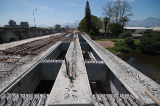
(Above): The underside of the newly constructed river bridge showing the T-beams and the permanent concrete shuttering.
(Below): Workers attach a precast concrete beam/ balustrade unit to the rail bridge.


