3 minute read
Appendix A: Group Simultaneous Pulse

from Jva Z14

Quick Start Guide
Quick Start Guide
Advertisement
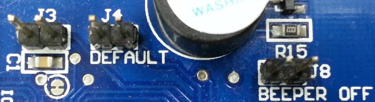
Jumpers quickly allow you to turn on and off different features, or reset the device to defaults. For more information on how to use the configuration jumpers and what each one does refer to “7.4 Jumpers” on page 38.
JUMPER FUNCTION J3 (Z14) Inhibit AC fail error. J3(Z14R) Tamper disable. J4 Factory default jumper Off to return programmable options to factory defaults on power up. J5, J6 & J7 Supplies +12V to the Common terminal of Relay 3, 4, 5.
Jumpers located on the top right hand side of the board
1.3 QUICK TEST OF CONFIGURED UNIT
Now that the Z14/R is configured to your fences requirements, it is a good idea to test the configuration before connecting the Z-Series energiser to a fence. The reason for this is that you could get spurious results if you test on the final fence and you will never be certain whether the issue lies with the fence, the Z-Series energiser, or the configuration of the unit itself. To test your unit it is best to connect your Z14/R with a test fence, this is done by connecting cables as shown in the picture below.
Power the Z14/R and then Arm it. The unit should begin pulsing and not show any alarms. Disarm the Z14/R and remove the fence cable as shown in the picture below.

Arm the Z14/R once again, after 3 pulses (unless you configured it otherwise) the unit should go into alarm as the fence will appear to be cut. Check that any sirens, strobes or relays correctly activate as you expect. If your site consists of multiple Z-series test each energiser one at a time as shown in the above photographs. Following that each energiser should be assigned a unique group ID with only one Z-Series device as the master unit (For more information see “13 Appendix A: Group Simultaneous Pulse Feature” on page 92). After that each Z-Series device can be connected together via the keypad bus and tested using group Arm and Disarm commands, they should all pulse in unison when armed.
Quick Start Guide
Quick Start Guide
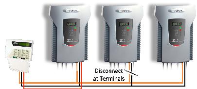
By disconnecting each Z-Series Energiser in turn from the keypad bus (shown in the above diagaram) you can check to see how each Z-Series device behaves under comms fail conditions. This way, you can test to see that the relays have been configured correctly for comms fail. Once you are satisfied that each Z-Series device is configured correctly you can begin to wire them to the real fence.
1.4 CONNECTING YOUR Z14/R TO THE FENCE
This is covered under “5.3 Examples of Fence (High Voltage) Wiring Diagrams” on page 30. In depth installation instructions begin on page 28. After the Z14/R has been wired up you can begin to protect your perimeter.
. For a full list of all keypad commands please see “10.8 Summary Of Keypad Functions” on page 68 012345 1234
Default Installer PIN Default User PIN First you need to connect the Z-Series LCD keypad to the Z-Series device, for more information refer to “10.3.1 Wiring up your Z-Series LCD Keypad” on page 61 . Once you have a keypad connected you can refer to the table below to control the Z-Series device. Key9 Key8
Key7 Key6 Key5 Key4 Key3 Key2 Key1 User PIN 0
0
1
User PIN Installer PIN User PIN
Command Arm/Disarm Silence alarm Enter Programming Mode Exit Programming Mode Arm All Zones X 0
1 2
User PIN User PIN
Arm Zone X where X is any zone number up to 15 Disarm all Zones
X
2
User PIN
Disarm Zone X, Where X is any zone number up to 15
1
Clear alarm memory


