4 minute read
Feature

from Jva Z14

Appendix A: Group Simultaneous Pulse Feature
13 APPENDIX A: GROUP SIMULTANEOUS PULSE FEATURE
Advertisement
13.1 GROUP SIMULTANEOUS PULSE FEATURE
In some Industrial Installations it may be preferable to provide the ability to link multiple Energisers into a group. When linked the individual Z-Series devices become a “Group”. Members of a group have simultaneous high voltage output pulses and act as is they are one energiser with multiple outputs. This is designed so that no possible combination of individual outputs can be dangerous. 13.2 GROUP MODE PROGRAMMING (OPTION 26)
A group MUST have only 1 master. The other Energisers in the group are slaves.
For the Z14/R Energisers, if there is no Master, a Slave will display Error 4 on the Status LED when Armed and it will not electrify the fence. This is a requirement for Australian Standards. For every other Z-series device, if there is no Master, each Slave will electrify the fence (pulses) when Armed. However, the simultaneous pulse feature will NOT be operating.
NOTE: 1. Do not interconnect the energisers via the keypad bus until after they are programmed. 2. If more than one keypad is used, they will need different addresses (see
“10.3.6 Changing the Keypad Messages and Address” on page 62. 3. If Perimeter Patrol is used any keypad in the system should not have address 2, (see “10.3.6 Changing the Keypad Messages and Address” on page 62). For all Energisers that will be part of a group, the procedure is as follows: 1. Make sure the key switch is turned off and IN1 isn’t shorted (note that the Z14R does not have a key switch). 2. Connect the battery. 3. On the keypad, enter [Installer’s code] *, 0, #. 4. Enter 2, 6 followed by the required value (e.g. 1 for master) then #.
5. Enter *, # to exit programming. 6. Connect the group using the keypad bus as the Group Mode Linking diagram. NOTE: At this time groups are limited to a master and 14 slaves (15 zones total)
Key3 0 1 2 3 4 5 6 7 8 9 10 11 12 13 14 15 Mode
No Group Master Slave 1 Slave 2 Slave 3 Slave 4 Slave 5 Slave 6 Slave 7 Slave 8 Slave 9 Slave 10 Slave 11 Slave 12 Slave 13 Slave 14
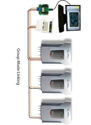
13.3 GROUP LINKING VIA THE KEYPAD “BUS”
The keypad terminals on all Energisers in the group are linked. Since only one Energiser needs to power the keypad, 3 wires are linked from one Energiser (preferably the Master) to the keypad (optional) and 2 wires to every other Energiser in the group. Do not connect the + lines between Energisers as this could result in some strange behaviour and possibly damage. NOTE the connections can be a star or daisy chain or any mixture. It is possible for a PC to be added to the group using a keypad to RS232 adaptor (PAE223).
Appendix A: Group Simultaneous Pulse Feature
Appendix A: Group Simultaneous Pulse Feature
We recommend following these steps in the right order: 1. Disarm all energisers in the group. If energisers are not disarmed
Step10 may not work correctly. 2. Program the keypad address using one of the energisers. 3. Program each energiser with its required address (Master address=1,
Slave 1 address=2...). 4. Connect any control/monitoring unit 12V, GND and Data to the Group
Master
5. Connect all the slaves Data and GND to the Group Master. 6. Connect the battery and AC power of the Group Master but do not arm.
7. Connect the battery and AC power of each slave. Note: Do not arm them until all the Energisers in the group are connected. 8. Wait 5 minutes for all the Energisers to synchronise with the Master 9. If there are more than one Z-Series keypad or control unit, make sure they have a different ID, then reset the group using keypad code: [User
PIN] *, 6, 8, # or Perimeter Patrol’s “Reset All” this will allow both keypads to be recognised by all energisers in the group. 10. If using a PTE0210 keypad, enter the key sequence *, 6, 8, # to automatically re-scan the group and check what energisers are connected. 11. Arm the group using keypad 1, 2, 3, 4, *, 1, 0, #, or by using Perimeter
Patrol. Make sure all Energisers are activated. Note:
1. Members of a group can be individually switched on and off; even the master can be turned off via input or key switch (note that the Z14R does not have a key switch). 2. A slave will generate a General alarm if the keypad bus is broken between it and the group master. 3. After programming the Keypad may be disconnected, it is not required for group operation. 4. When connected to Perimeter Patrol, the arm/disarm function of a keypad is disabled. Control of these functions is through the Perimeter
Patrol interface.
Appendix A: Group Simultaneous Pulse Feature

ZLM4 User ManUaL