
1 minute read
5 Installation

from Jva Z14

Installation
JVA recommends installation by qualified technicians. 5.1 INSTALLATION STEPS
Advertisement
1. Read the entire manual first! 2. Design and build the fence. (Beyond the scope of this manual.) Ask your distributor for help if required. 3. Decide where the JVA Z14/R is to be mounted. If on an external wall it should be housed within a waterproof equipment box and definitely not in direct sunlight. 4. Remove the JVA Z14/R PCB chassis from the housing by removing the 2 screws.
5. Mount the housing by using 4 screws through the rear of the box. 6. Replace the PCB chassis. 7. If using a keypad, remove the rear housing of the keypad and fix it to the wall.
8. Wire the low voltage cables to the PCB terminals*. 9. Wire the high voltage cable to the PCB terminals*. 10. If earth monitoring is not going to be used on the fence, connect a bridge wire from earth out to earth return. 11. Ensure that the key switch is off. 12. Fit the battery leads to the battery. The status light should blink twice repetitively to show mains fail, unless J3 is fitted. 13. Mount the 230 – 16V transformer and connect the 16V side to the
Z14/R 16V input terminals. (AC is not polarity sensitive.) 14. Do not connect a live or neutral to the earth terminal.
15. Replace the front cover. 16. Turn AC power on. 17. Arm and disarm the energiser via the keyswitch or keypad, if fitted. The status light should stop blinking. 18. Arm the unit.
19. Check to ensure that a short anywhere on the fence triggers the alarm.
Ensure that the user understands how to change the User PIN and is in possession of this Installer/User Manual and the installer’s contact details. * NOTE: Keep high voltage and low voltage cables at least 30mm apart. Do not run high and low voltage cables in the same conduit.
5.2 INTERIOR CONFIGURATION
Installation
Installation
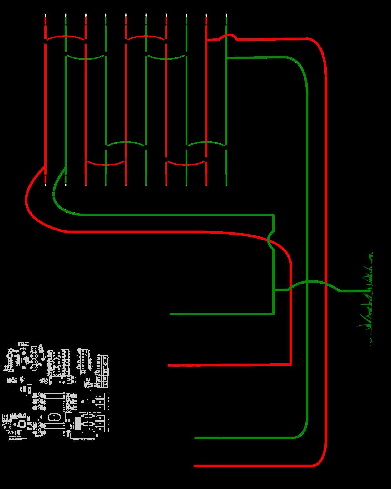
Z14/R energiser configured for conventional fence operation

Z14/R energiser configured for Bi-polar operation


