ABPL20033 - Construction Analysis
Semester 2 - 2017
Dr Alberto Pugnale – Subject coordinator

Dr Sofia Colabella – Senior Tutor Michael Collins– Tutor
Kai Lin, 825663, 17/10/2017
Inarc Architects- Bluff house, Tutorial no.6


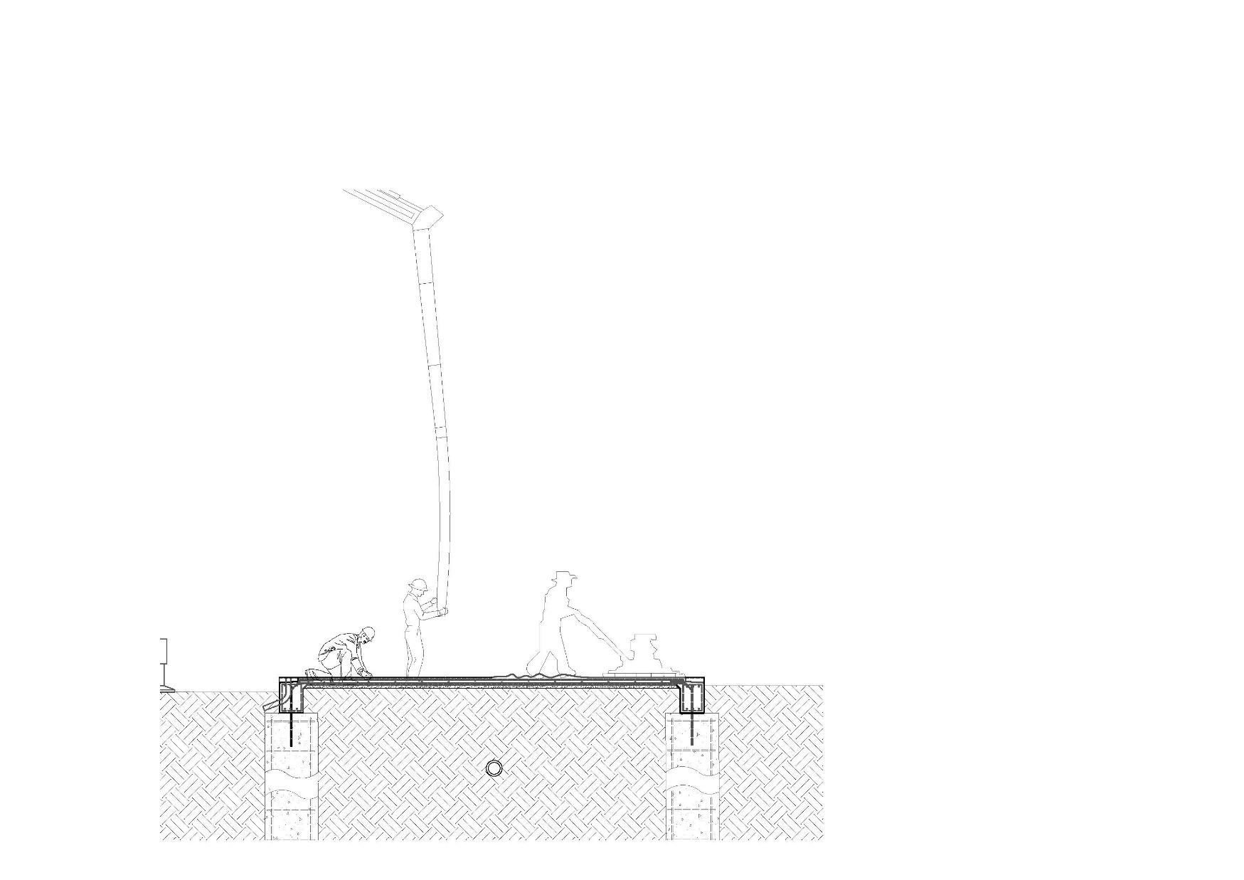

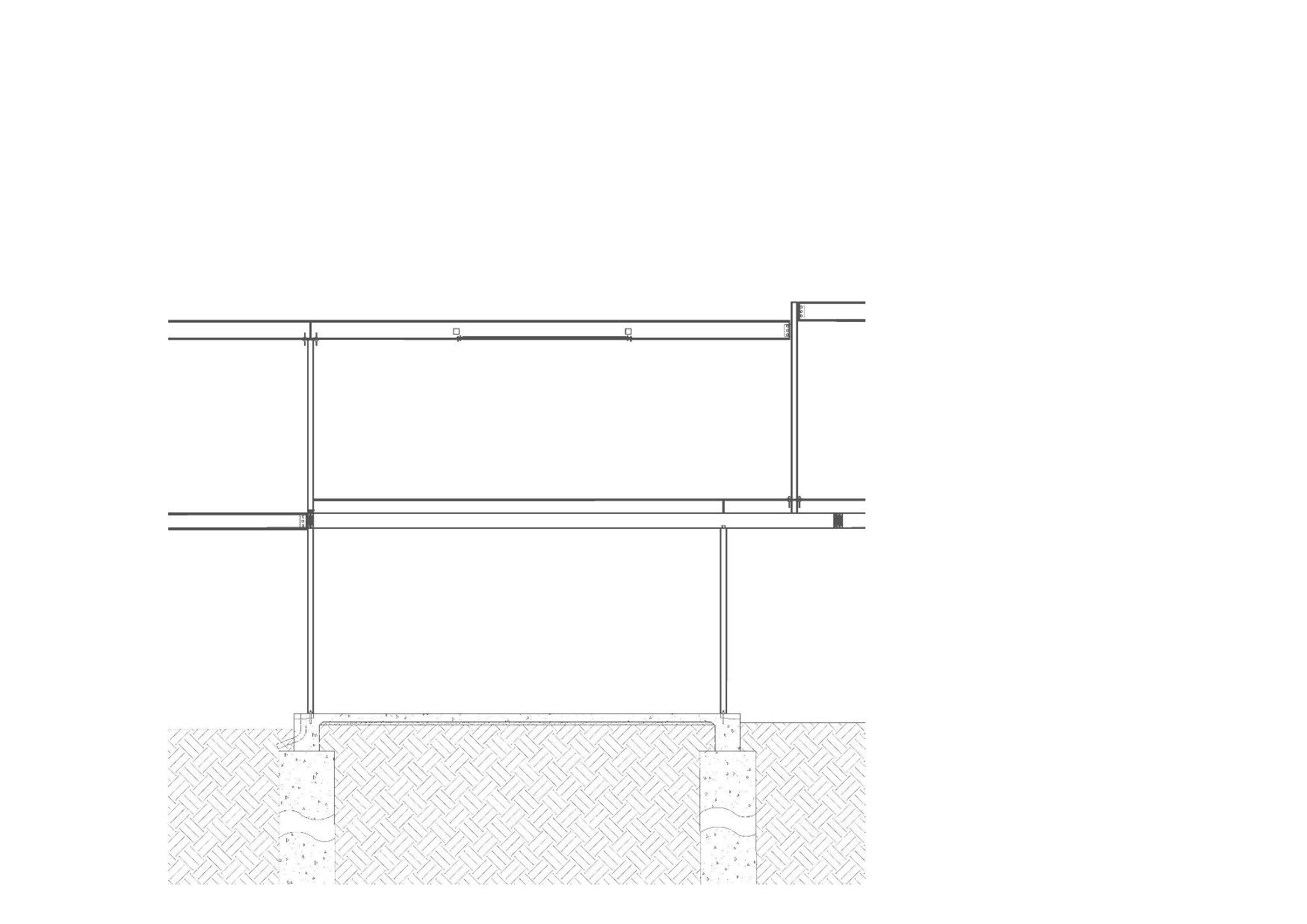
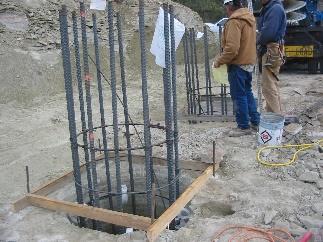
Footings have been designed for a minimum safe bearing pressure as 350kpa for bored pier 2 and bored pier one has much higher capacity of bearing pressure. The reinforcement inside the bored pier are the most important element inside bored piers. In Bp1, the code of the reinforcement is 10N20, R10-300CRS which means there are 10 20mm diameter vertical reinforce bar in the pier And they are equally spaced. The CRS between two horizontal circular ligs is 300mm. In Bp2, it has 6 16mm diameter vertical reinforce Bars and the CRS is 300mm as well. The minimum cover for the reinforcement is 75mm, because it can reduce the effect of corrosion from Moisture or deformation from land clipping.
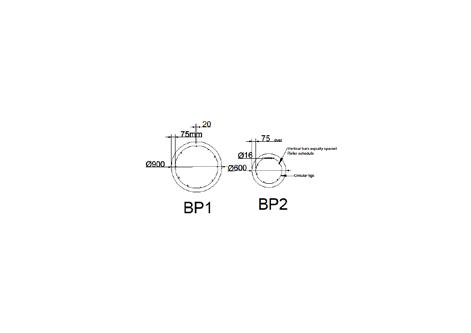
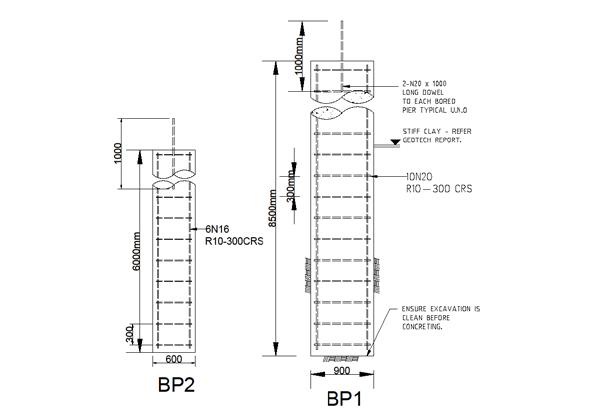
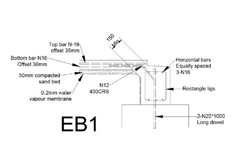
The N20*1000 long dowel sticks out the bored pier, because it is the reinforce bar for the edge beam and the bored pier.
The bored piers are not common footing system to a residential building. The bluff house took the bored piers as the footing system because the soil classification of the site is ‘Class p’. As my research shows, the site is located on a transition point between two geologies and it results in a land clip affect the site. And that is the reason for taking 8500mm long bored piers.
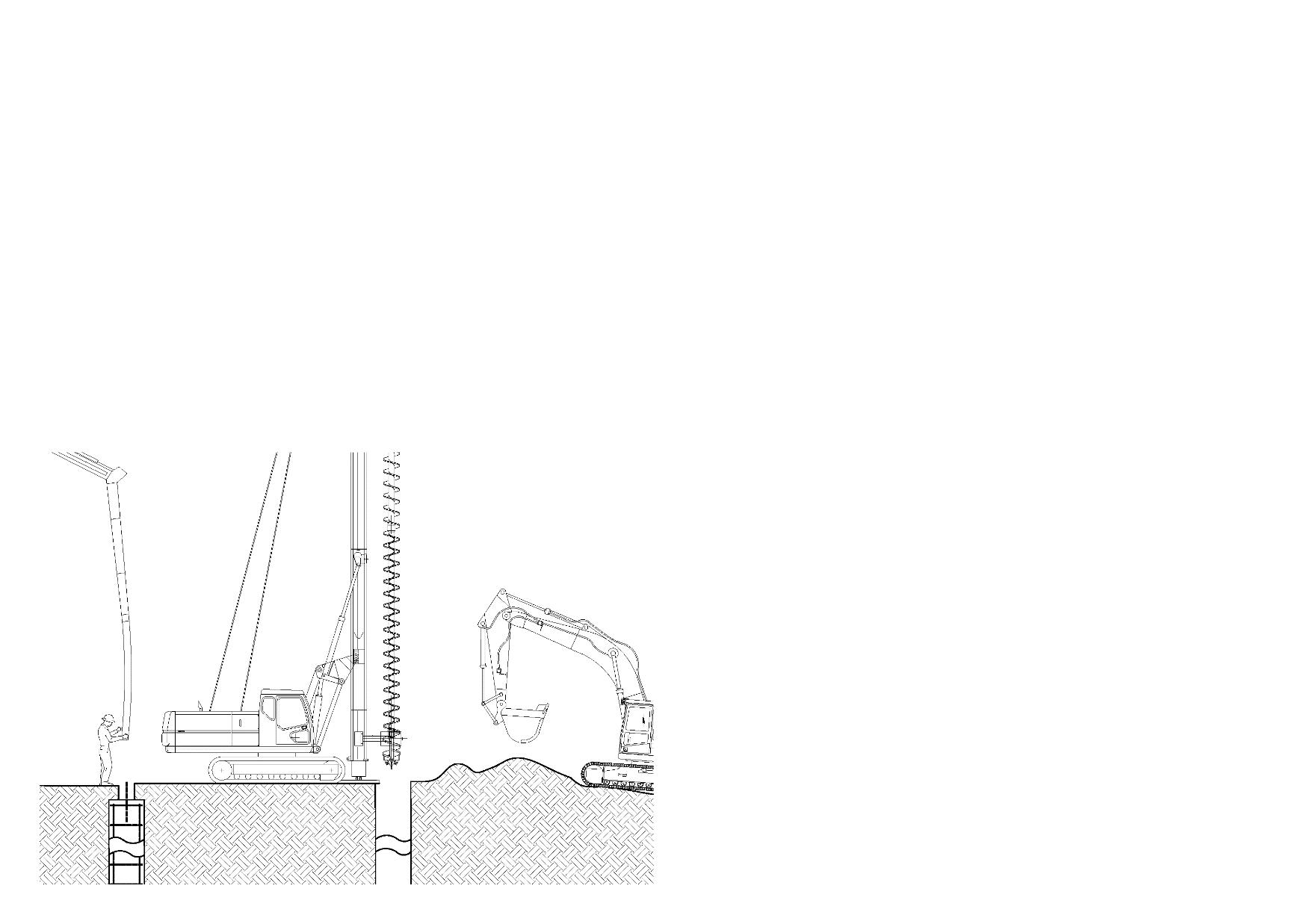
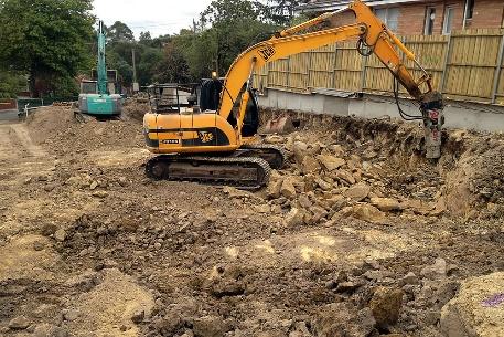
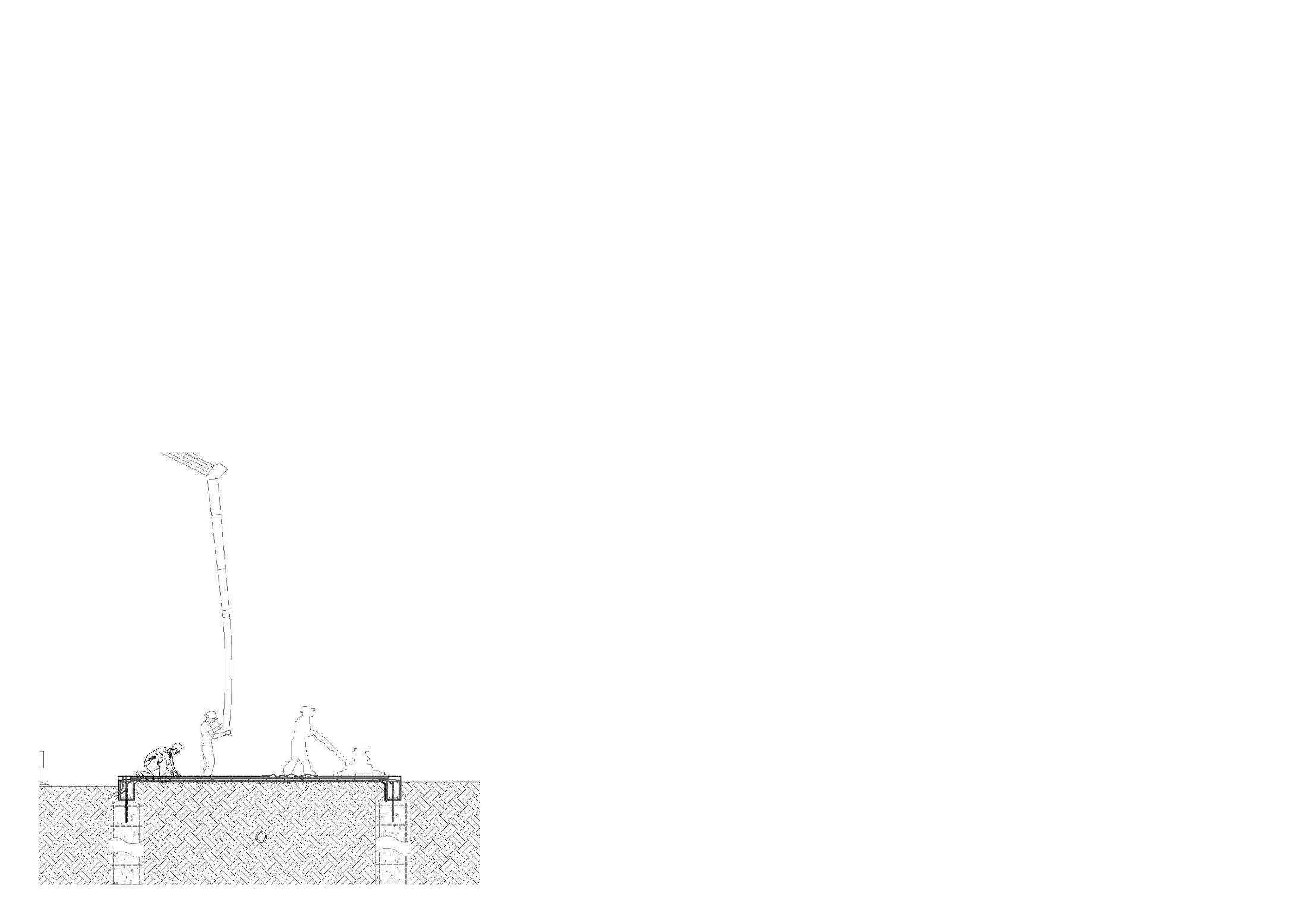
After demolition of the existing house, the excavation is the next step. Firstly, the excavator will clear up the site such as remove unusable materials from the site and remove loose clay or stones on the surface of the soil.
The pier driller will drill the hole for bored piers .
Secondly, builders will excavate the underground service channel for placing service pipes, underground power connection to the house, NBN wires, sewer pipes and so on.
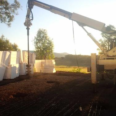
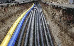
After the holes was drilled, the reinforcement will be placed into the hole. Builders have to ensure the excavation is clean before concreting. And then pour concrete into the excavated hole.
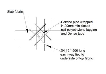
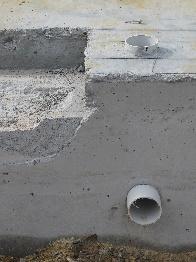
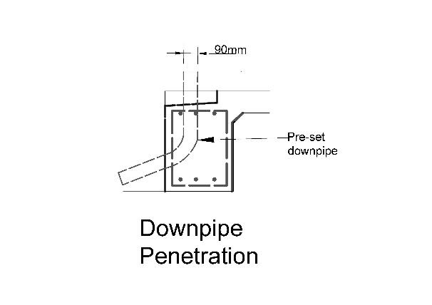
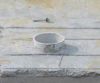
The downpipe was casted into the Concrete slab by the fasteners. So it create a kind of penetration to the concrete slab. There are more service pipes needs to penetrate the Concrete slab such as gas pipe, water pipe and sewer pipes.
All pipework cast into concrete is to be sleeved or lagged with appropriate compressible materials and external protections are needed.
The service pipe wrapped in 20mm with polyethylene lagging and tape.
2N-12*500mm long bars are preventing the service pipes from getting external damage.
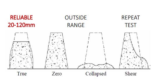
Before placing the concrete, workability has to be verified on site by means of a Slump Test. The slump is usually measured using a standard sized hollow cone that is first filled with concrete and then subsequently carefully lifted off the cone. The amount of slump of the sample from its original height inside the cone is measured and checked against the expected level of workability The more the ‘slump’ of the sample, the more the water content of the mix. The concrete sample should remain intact and symmetrical during the test. The normal range of slump is 20 –120mm。 But for the reinforced concrete slab, the workable range of slump is 50-100mm.
Plastic chairs
Sand bed (underneath)
Plastic chairs and sand bed are both lost formwork for the concrete slab. Sand bed is used to flatten the soil underneath.
Reinforcing mesh
Water Vapour membrane
Water vapour membrane have a minimum thickness of 2mm. All pipes penetrating membrane have to be wrapped with plastic and taped to membrane. It provides moisture preventing.
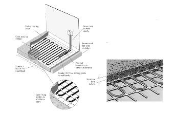
Electric slab heating system is operating in this building. The electric cables are fixed to the reinforcing meshes. And then do the concreting.
Many reinforced bars are placed into the concrete slab and the beams to enhance their cavity of pressure bearing and the durability. There is a N12 reinforcing bar connecting the edge beam and the concrete slab which has the same function as the long dowel.
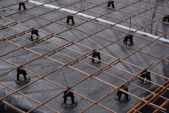
The offset distance is the corrosion protection for the steels and help the system to against fire as well.
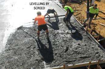
Builders need to level the concrete slab by using screed and spreading concrete by using shovel.
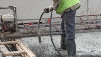
Benefits for Vibrating the concrete:
Increased strength
• Increased abrasion resistance
• Increased durability
• Decreased permeability
• Minimised shrinkage
Immersion vibrators are known also as ‘pokers’ or ‘needles’. They consist of a tubular housing with an out of balance weight that causes the cylinder to wobble and to transfer vibration to concrete • Immersion vibrators are inserted vertically in square or offset patterns by hand. With each immersion they compact concrete within up to a 600mm radius.
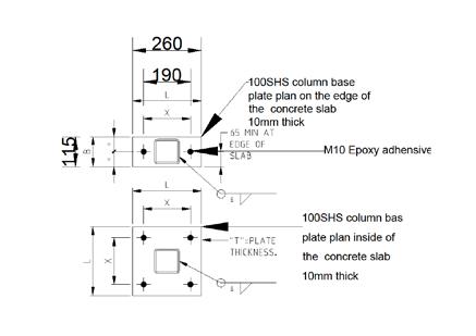
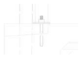
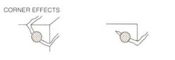
The base plate was directly fixed to the slab where appropriate with M10 epoxy adhesive anchors with 1000 max center with 65mm minimum edge distance. This is very useful when encountering the corrosion defects and crack in the corner. At least, the primary structure will not get affected by a small corner effects.
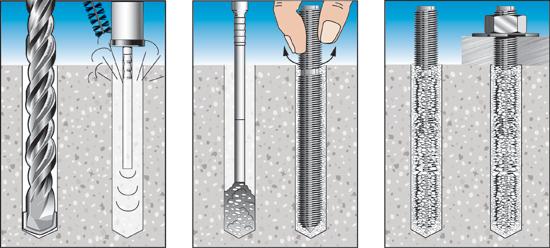
Chemical setting- M10 epoxy adhesive anchors

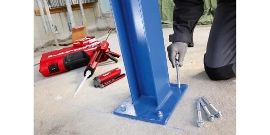
Drill hole by driller- > clean up the hole with a small brush-> insert the epoxy anchor into the hole ->it will have chemical reaction inside the hole and then fasten the anchor.
Mark the position of primary structure by using dark mark pen or marking spray. After mark down the position of each element, builders will build up the structure more accurate.
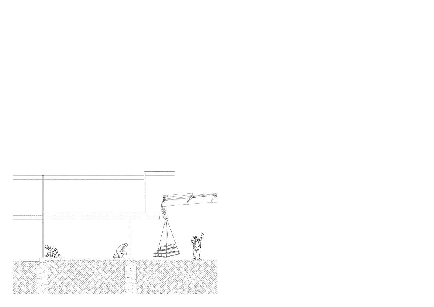
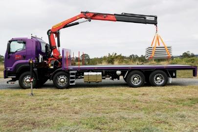
Truck deliver materials to the site and then the crane unload the materials to the site.

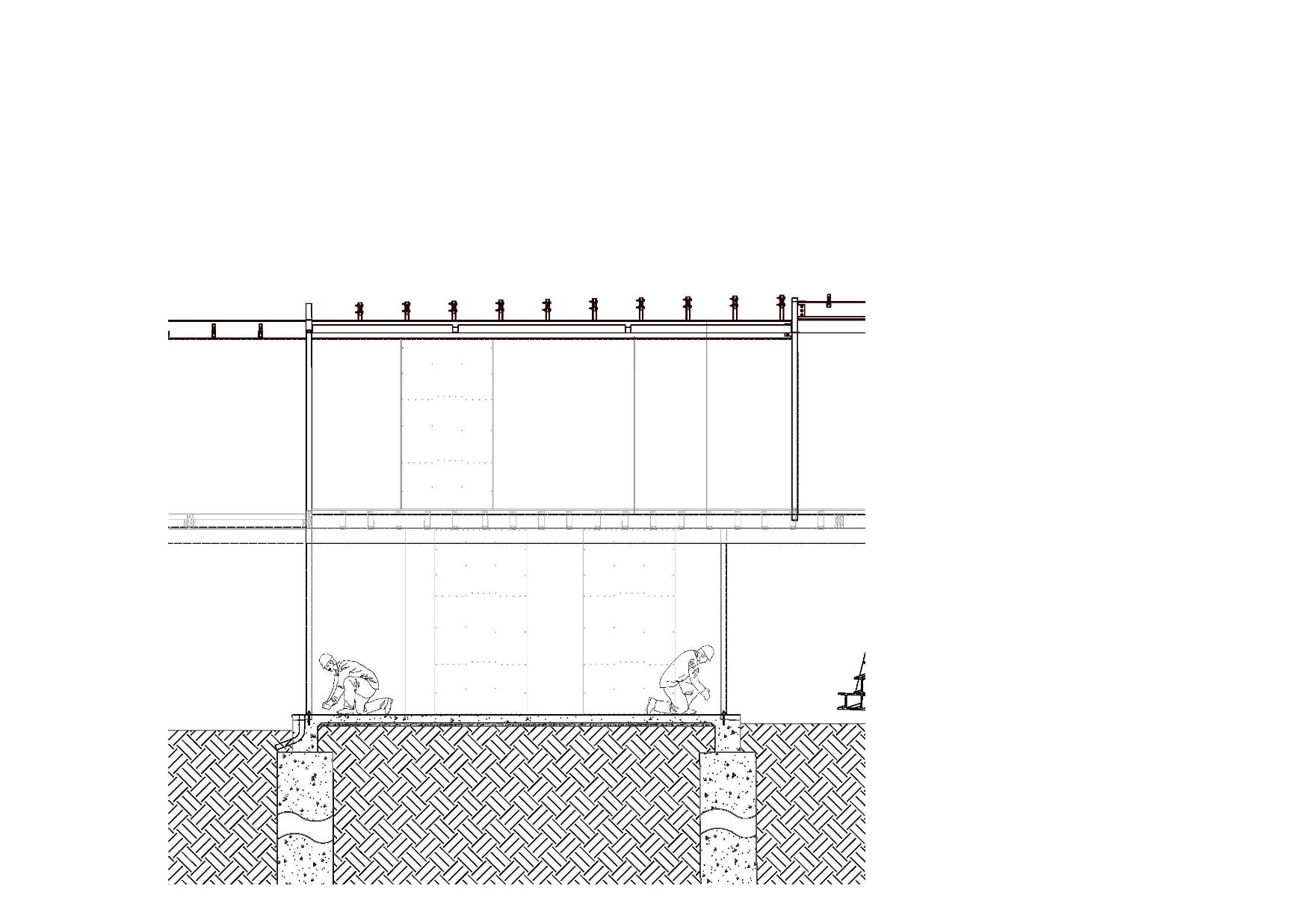
The roof bracing D1 is connecting to the S1 which is a horizontal SHS element which across the roof. When a primary structure is built up, it will against the lateral force such as wind loads, earthquake loads. The D1 bracing is built to against the lateral force.
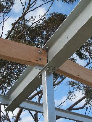
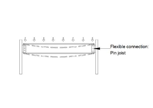
This joint is a kind of flexible joint which using a cleat plate to connect the beam and the column. And there is height difference between the RB5,2 and RB5.1.
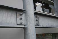

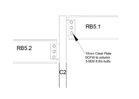
All movable things on the structure result an vertical or lateral load. Thus the primary structure has to be able to bear all loads on the structure. The flexible connection, pin joint is a good way to increase the load bearing capacity of the structure. Because when there is live load apply on the beam, it allows the beam to bend a little bit and then it will be able to bear more loads than other traditional joints.
The transverse stiffeners for shear (i.e. web stiffeners) are used to increase shear capacity in a beam web. It provides the beam more vertical load bearing capacity.



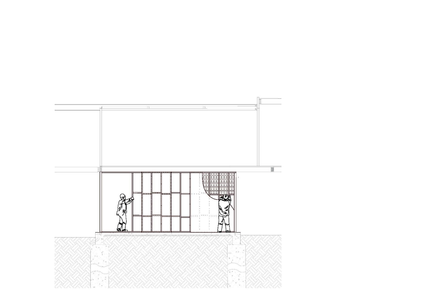
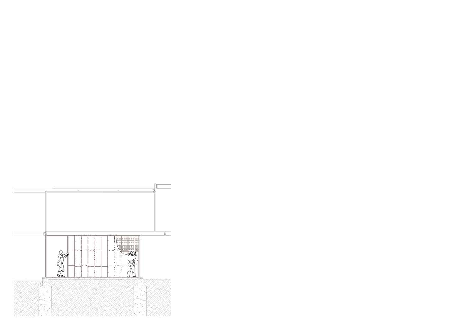
Wall type 01B: 300mm thick.
90*45 timber studs with insulation tontine ‘insuloft’ polyester batt Rvalue of 2. The wall is a cavity wall with insulation infill.

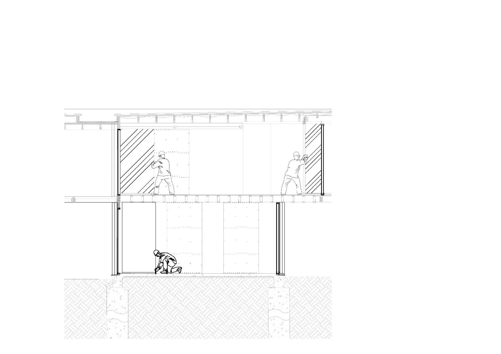
10mm thick plaster board is placed in the internal side.
The insulation is the thermal insulation. The function of the insulation behave like ‘thermal breaking’.
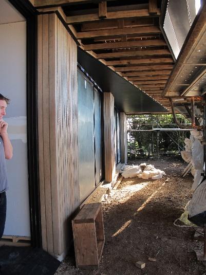
80*19mm timber vertical lining board
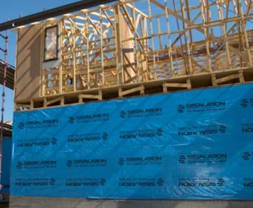
Vertical timber lining boards


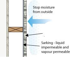
The Sarking is the vapour permeable membranes and it’s flexible sheet material as well. It is liquid impermeable and vapour permeable. Thus it is very useful on controlling moistures from outside the building. The other function of sarking is wind break, sarking can stop wind blow into the house, thus it provides comfort to house owners.
Plywood shall be nailed to the timber frame using 30LG* 2.8mm diameter Galy Flathead nails or equivalent.
Fix bottom plate to the slab with M10 chemical injection anchors at each end of bracing length.
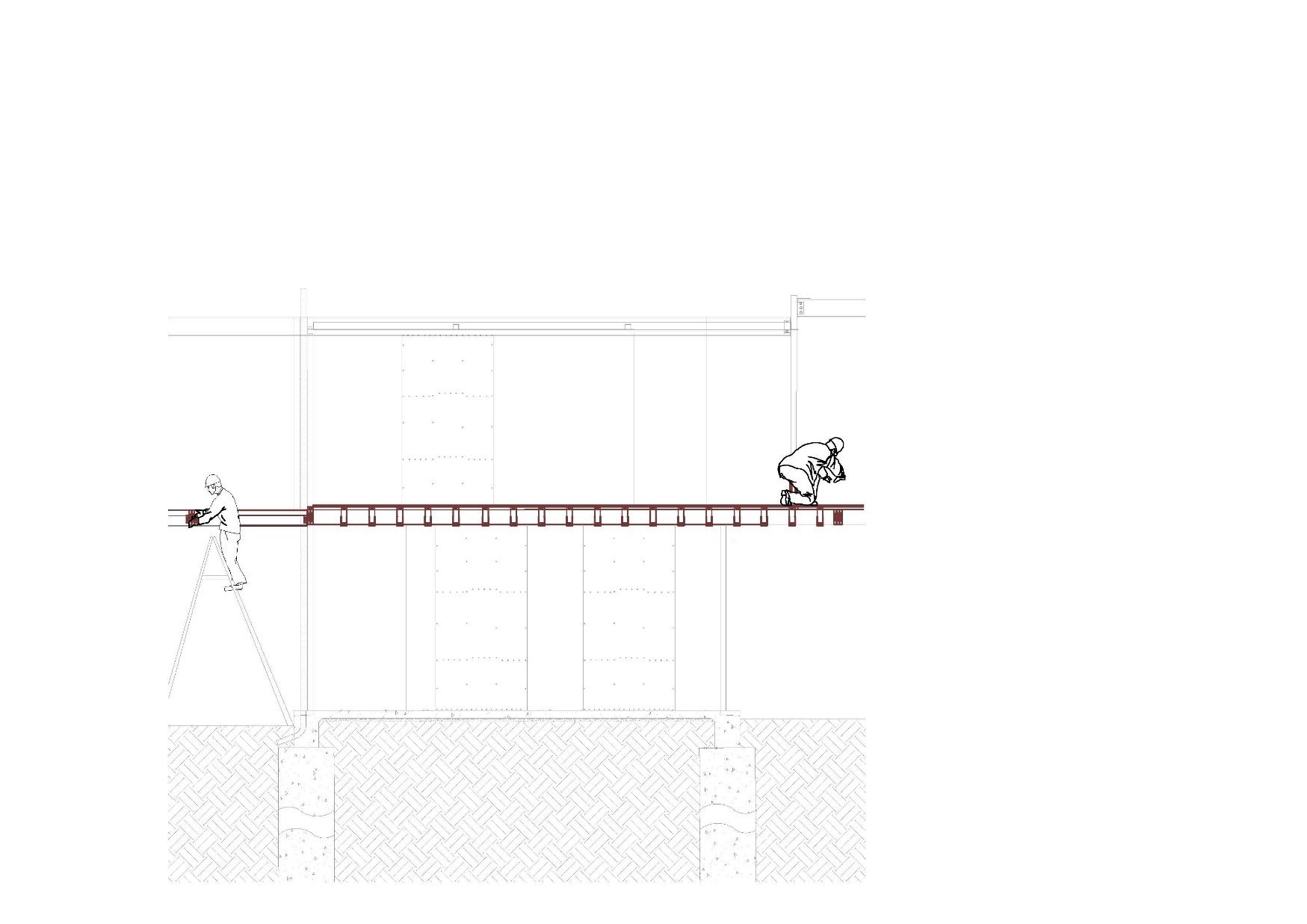
Deck joist are horizontally placed on the joist hanger which is sitting on the 120*45 timber fixing plate to fixed to the floor beam 1B13.
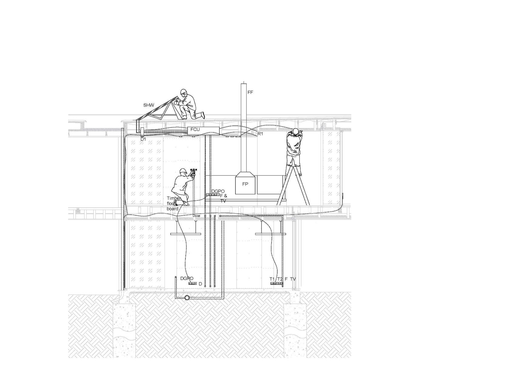
Open web trusses floor joists allows small services wires or pipes to go through the floor joist to first foor or controlling appliances on the ceiling such as downlights, exhaust fans.
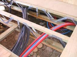
The open web trusses floor joist has the depth of 300mm and the standard grade is MGP10, The CRS is 450mm with 90*45 chords.
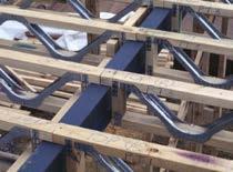
The connection between beam FB6 and the floor joist.


Firstly, the 90*45 chord lay on the top of FB6 and use 2 3.15mm diameter*75 LG skew mails through each member.

Secondly, the joist will be fastened to the joist hanger.
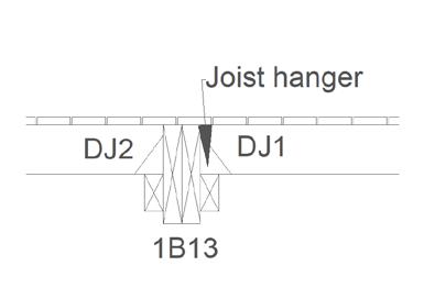
Lastly, the M16 bolt cross the joist and floor beam and then fasten the structure.
The builder is placing the 19mm particleboard on the floor joists. As we can see, some white glue are used to fasten the particleboard temporary.
After placed panels on the joist, builders will use nail gun to further fasten the panel onto the joists.
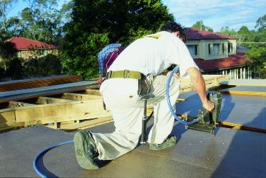
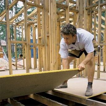
When live load is existing on the intermediate structure, the load will transfer to the floor joist from the 19 mm particleboard. And then transfer to the floor joist beam to the timber studs below the beam. And then transfer to the concrete slab and to the footing system.
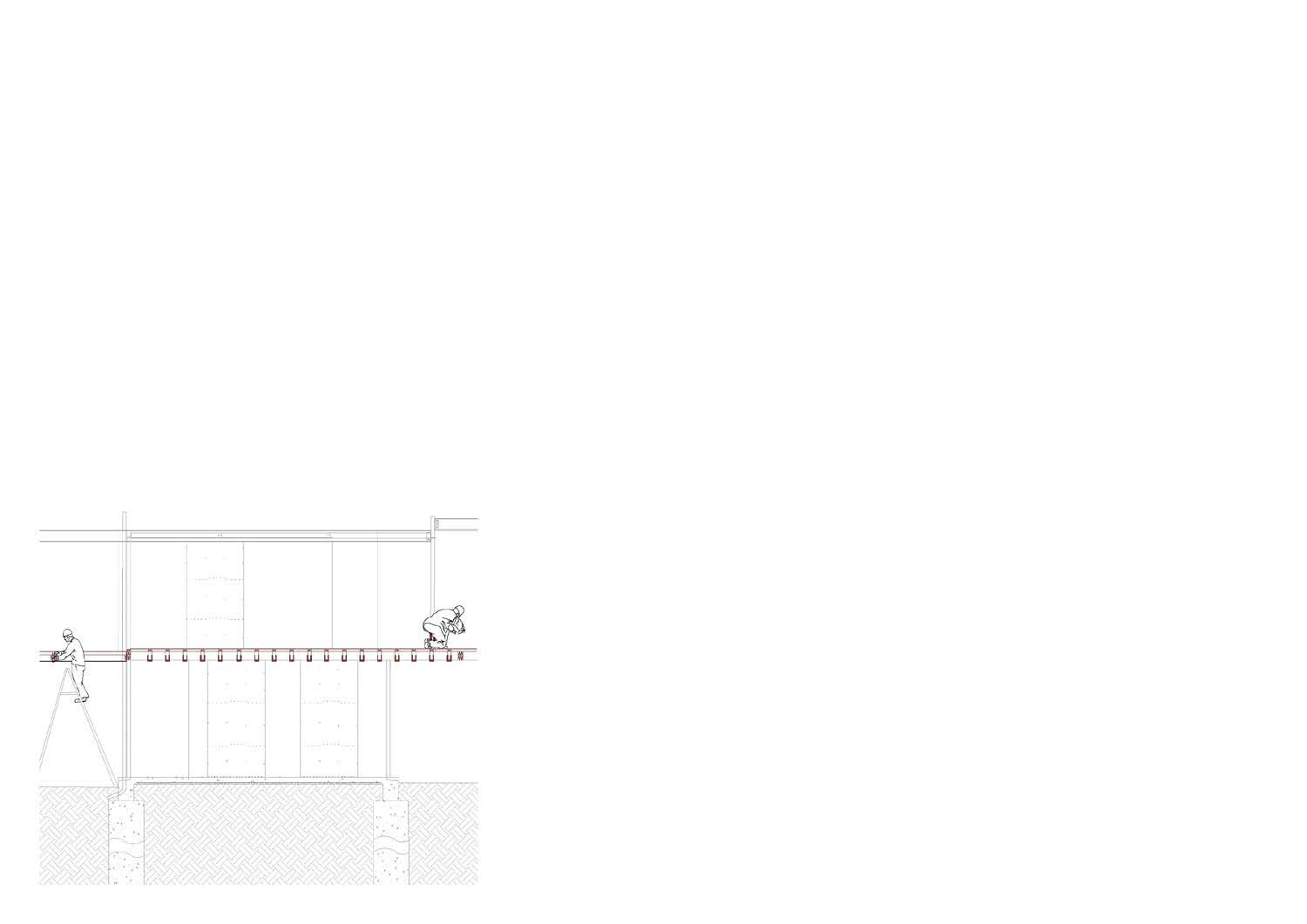
Roof beam 1-4
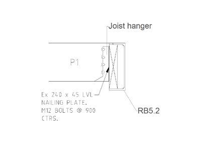

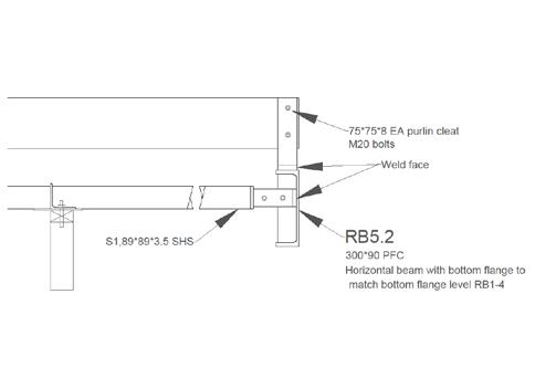
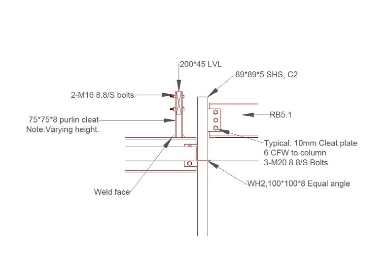
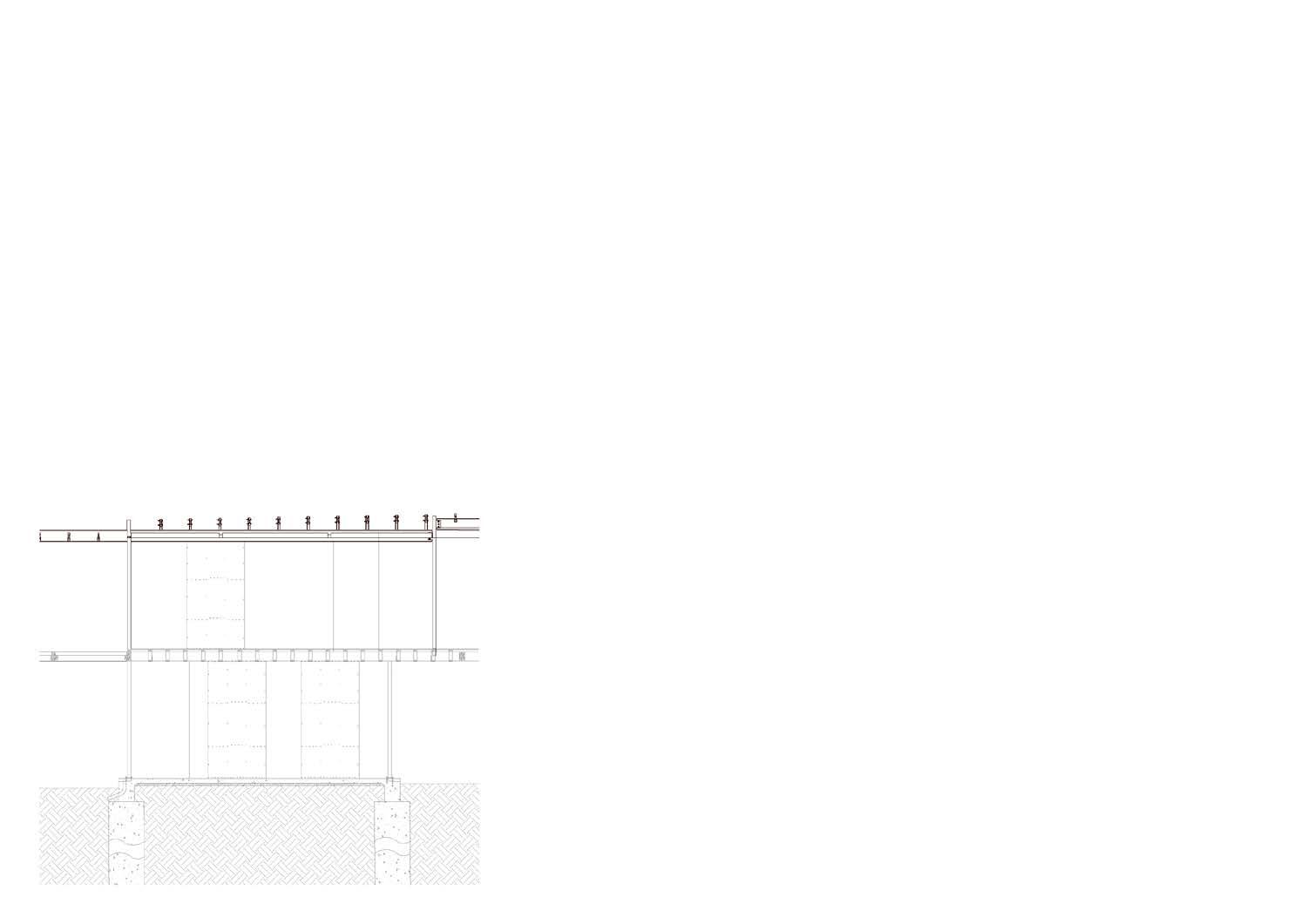
Purlin cleat WH1
Purlin S1
D1,roof bracing
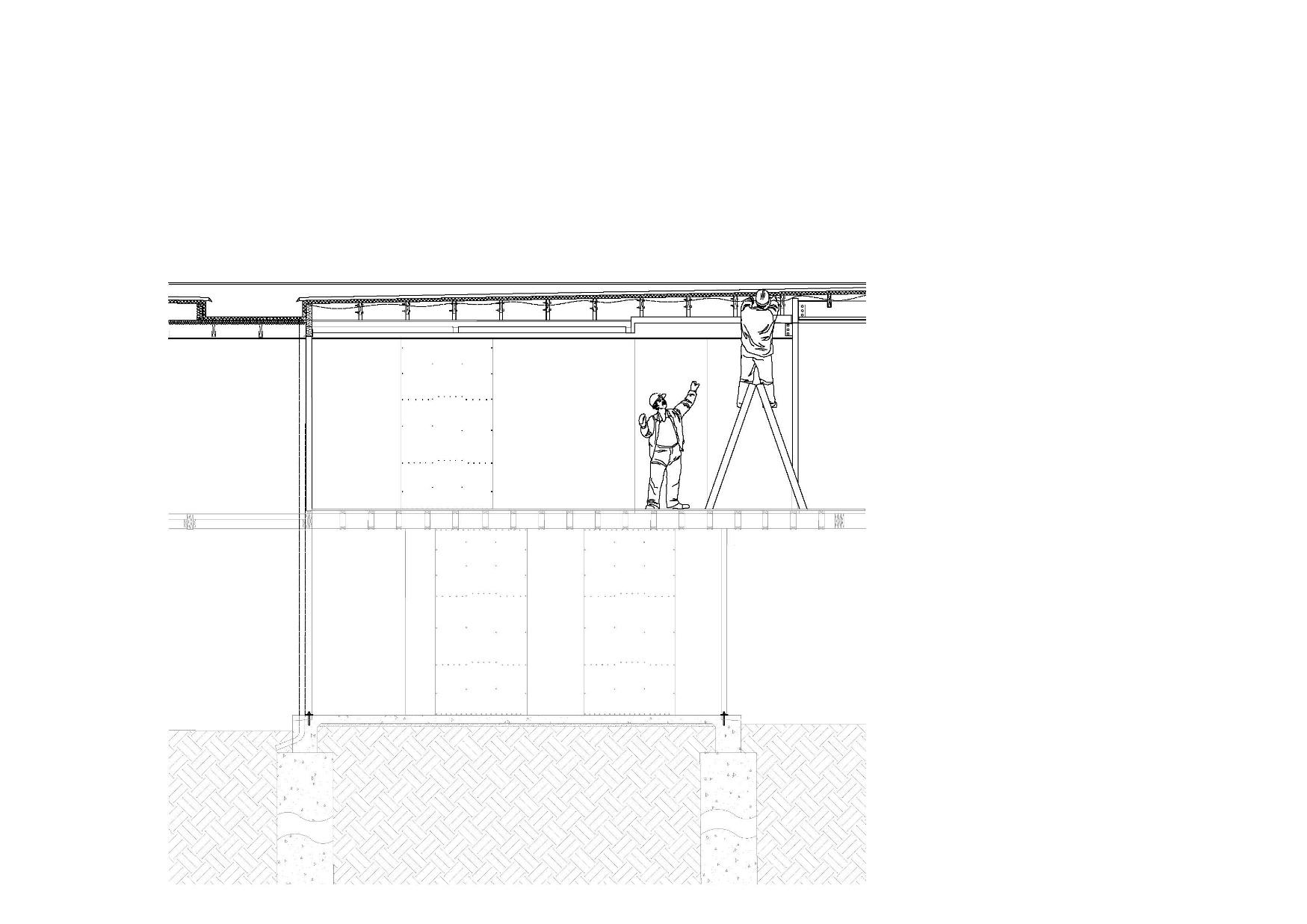
The box gutter on the roof is a kind of rainwater collection method, it collects rainwater from the roof and transfer to the reclaim water tank which is underground and next to the swimming pool.
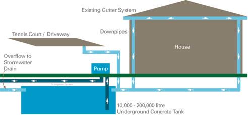
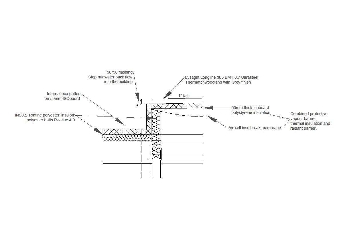
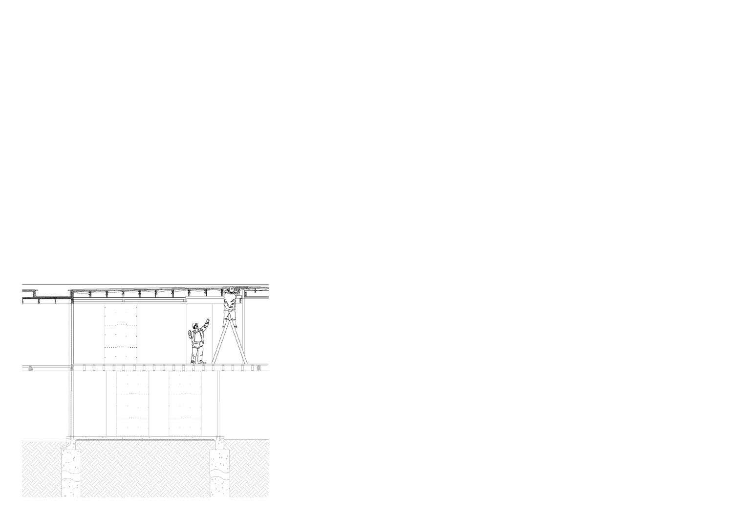
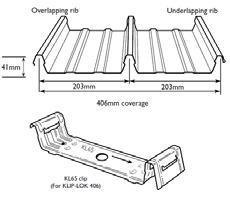
The Lysaght longline 305 BMT 0.7 is a overlap roof cover, it needs connectors to connect each metal plate to make sure they are waterproofed.

The wire net is using to stop leaves blocking the box gutter.

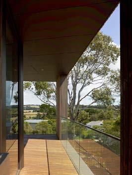
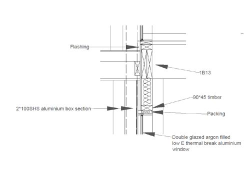
The downpipe is getting concealed by 100 SHS aluminum and the protective membrane is on glass to protect the glass from scratching.
The balustrade is using a kind of free frame design, it has aluminmum capping on the top of the balustrade and by follow the safety enquires in NCC, the balustrade has to be higher than 1000mm,

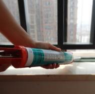
After the window frame is built, the builders will use Silicon Sealant to seal all gaps between structure elements and window frame for wind breaking. And it is a good strategy to keep thermal energy inside the building. Designed for clients comfort.

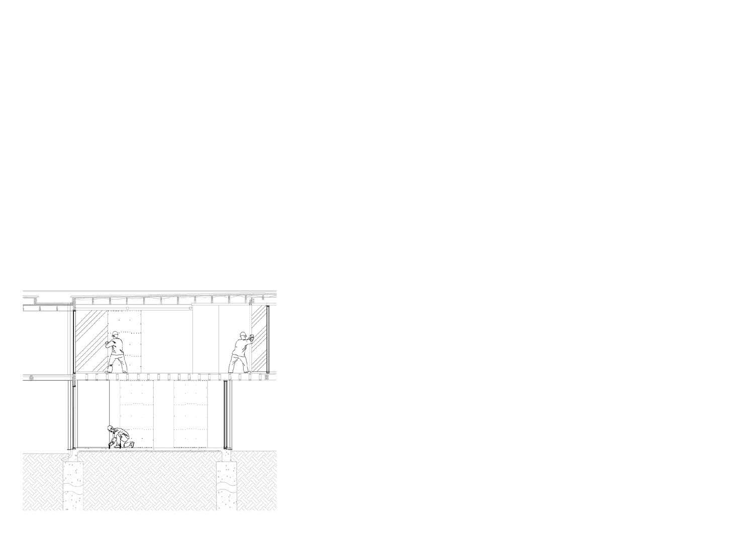
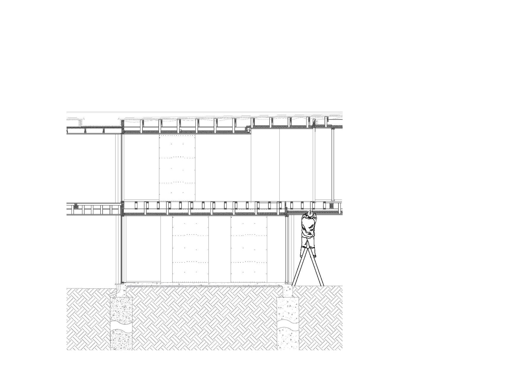
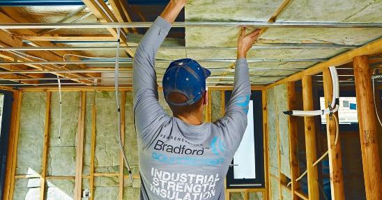
INS 01. Ceiling insulation between floors for sound absorption laid on suspended ceiling system.
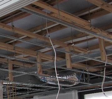
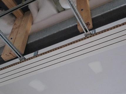
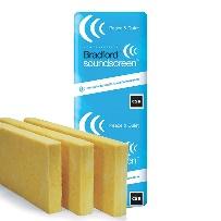
Material: CSR Bradford soundscreen plus r2.0, 75 mm thick.
The builder is placing the sound screen insulation to the suspended ceiling.
Bulkhead:
The batten is directly screwed in the timber block which bolted to the purlin or floor joists.


The insulation on the roof is more about thermal breaking rather than acoustic, and it has R –value of 4.
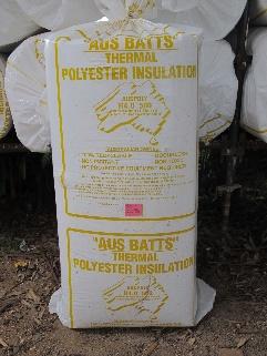
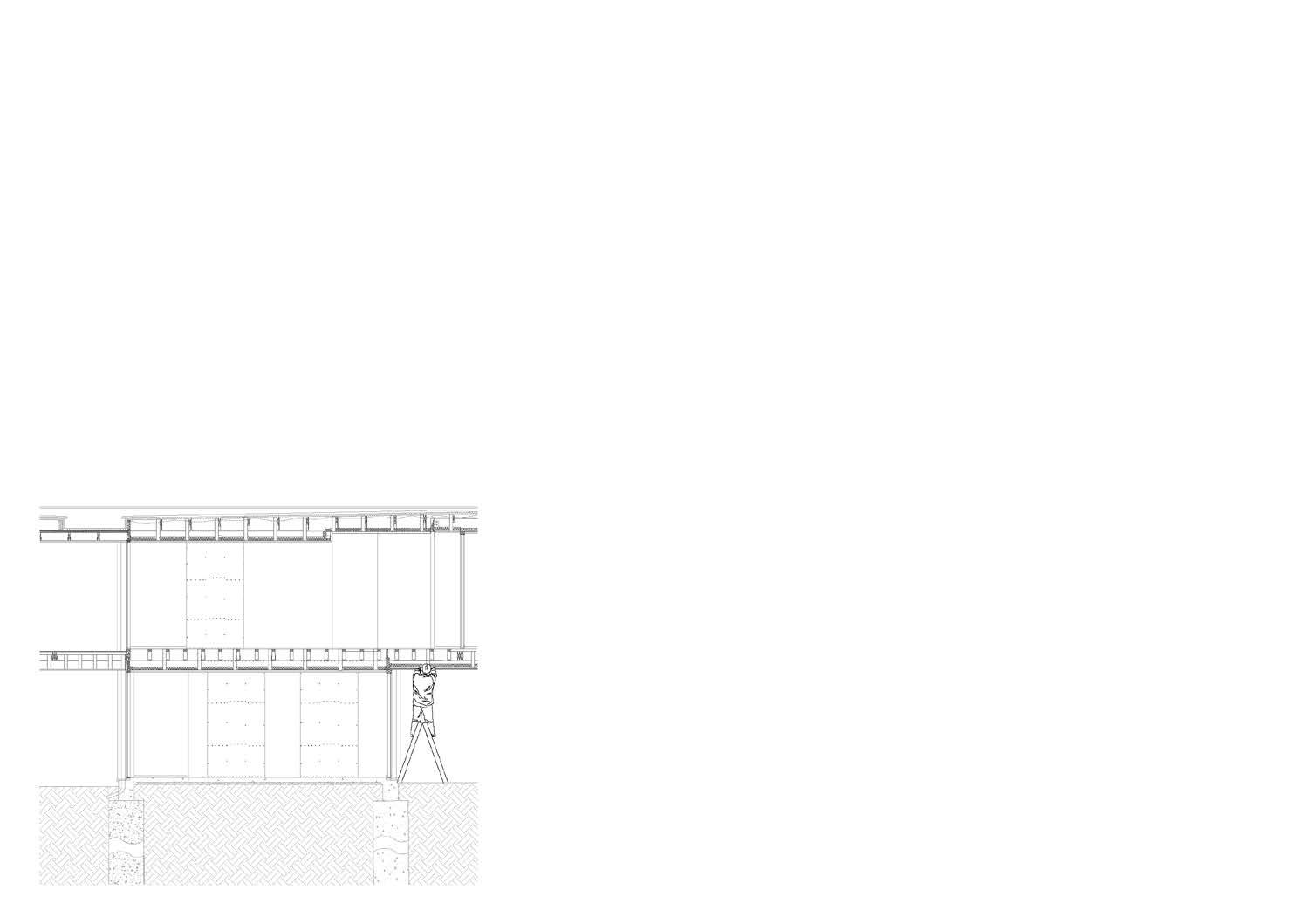
The advantage of using suspended ceiling is service pipes can free transferring in the space between floor joist and the ceiling

The heating zone provide electric slab heating to the study area and the corridor. In the slab, electric cables are fixed on the reinforcing meshes. And it will have a zoning system To control the temperature on each zoning area.
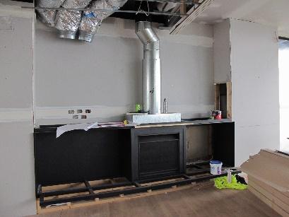
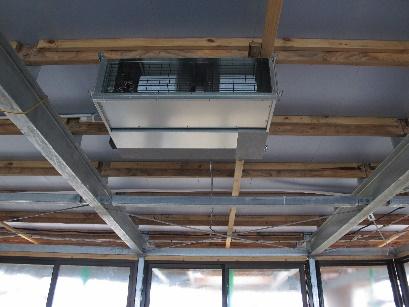
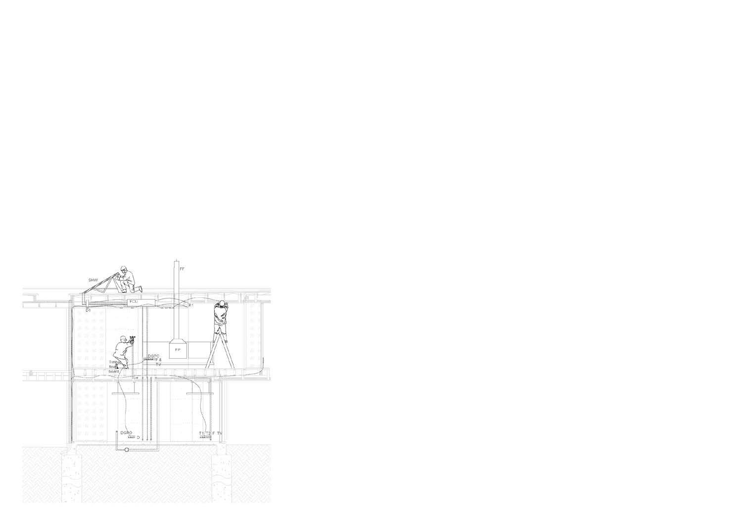
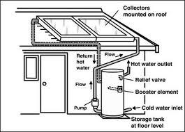
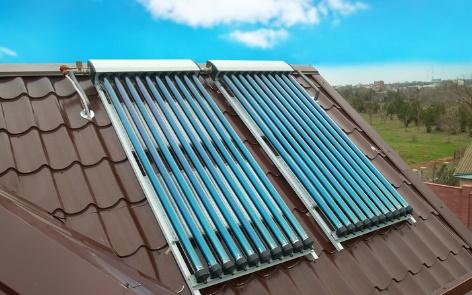
Evacuated tube type solar hot water panel. It combines with the hot water unit, when water is heated by the sun, it flows into the hot water tank.

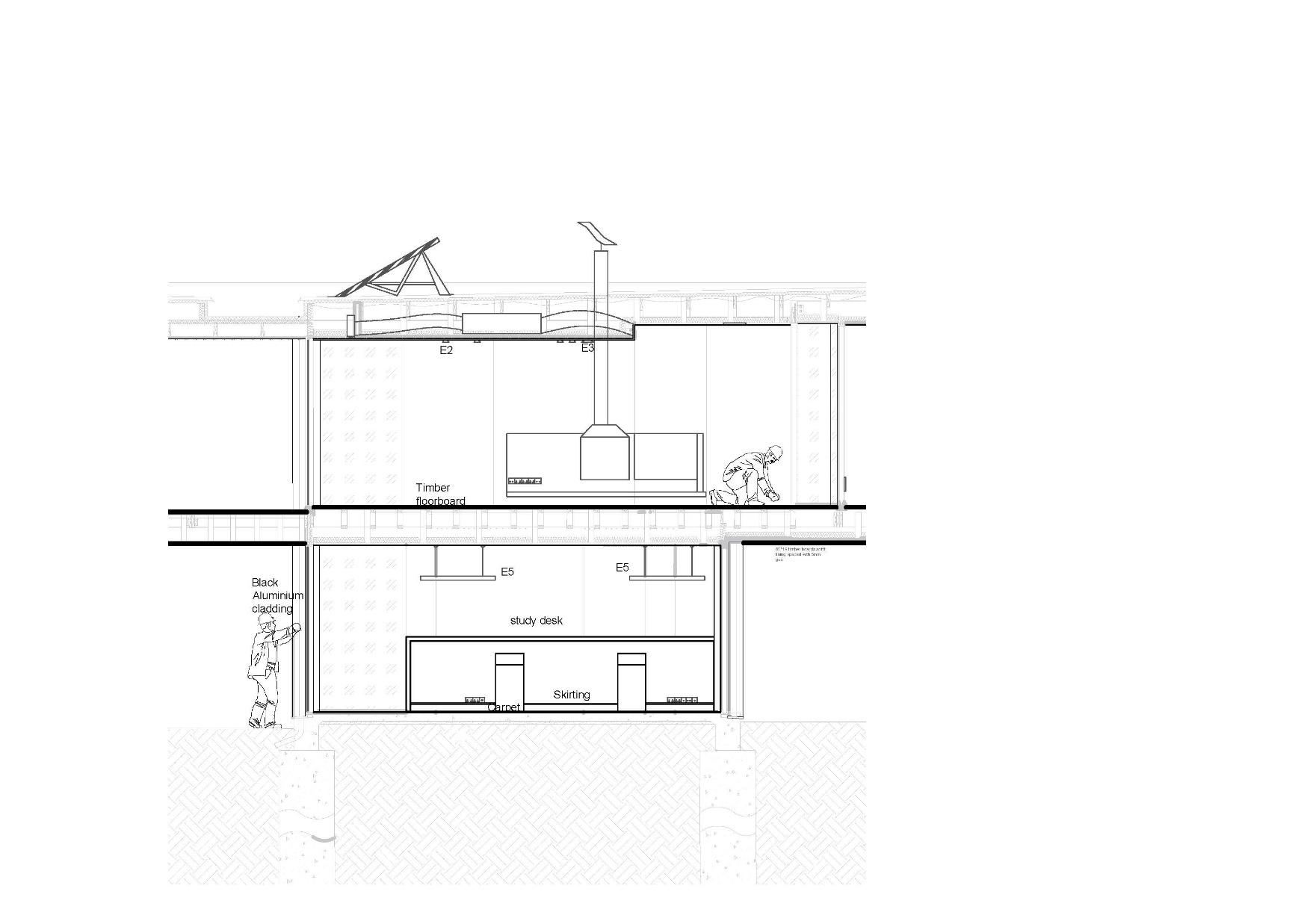
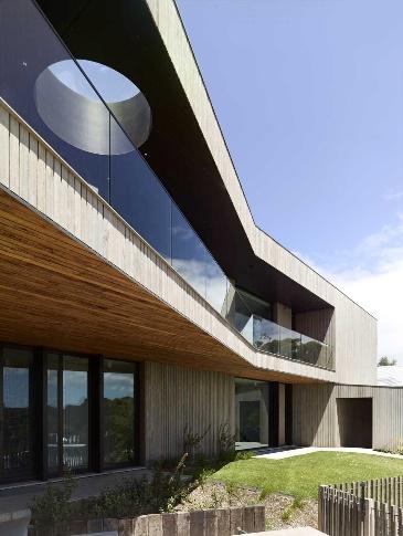
80*19 mm Vertical timber lining cladding will be fully install on The building.
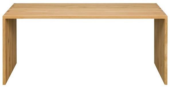

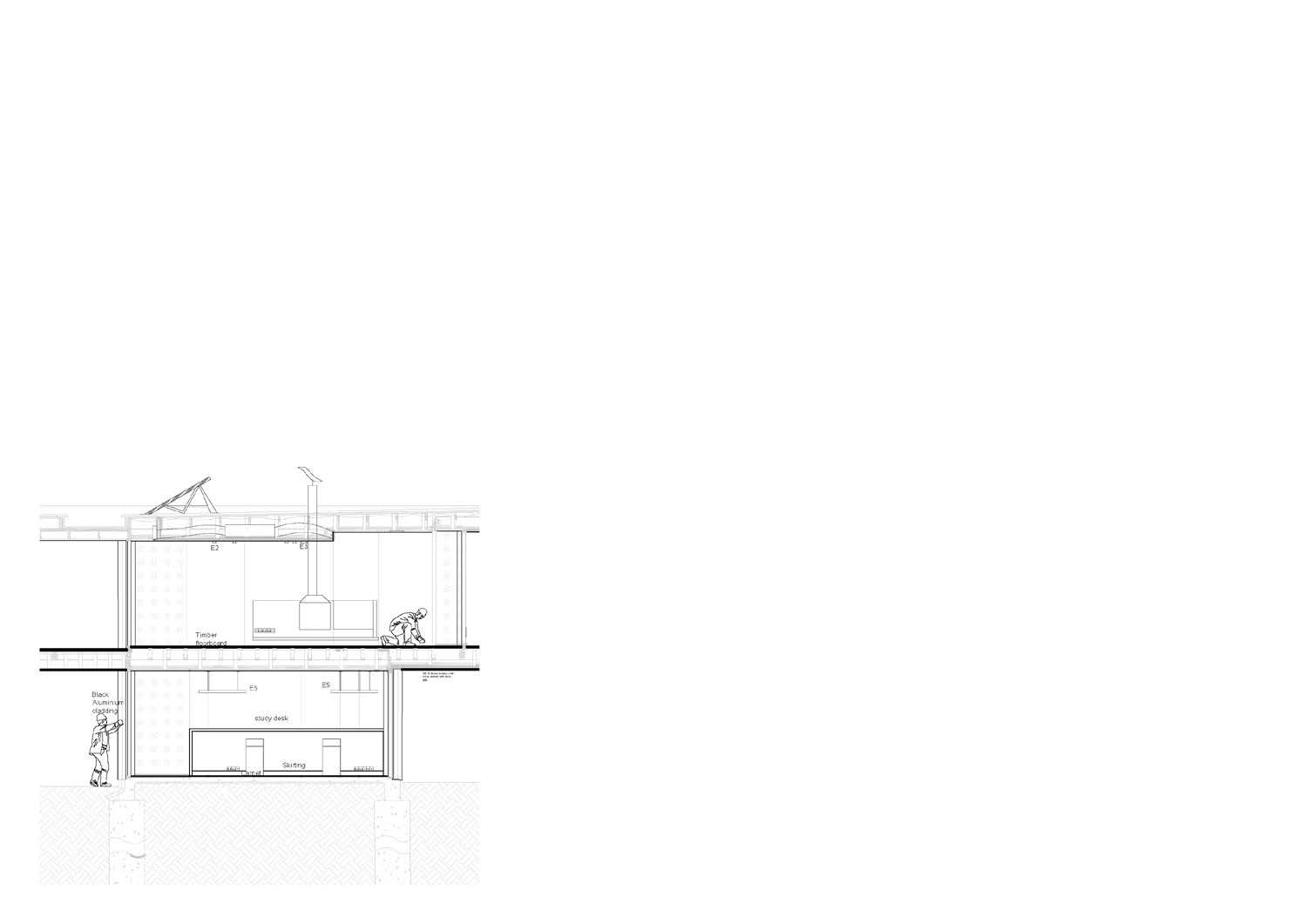
Study desk.
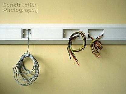
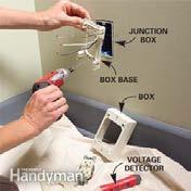 Electric power point box
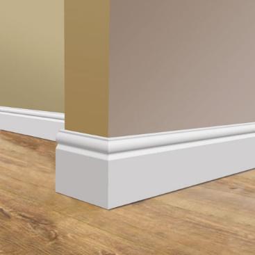
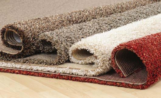
Carpet for study area and timber floorboard for first floor.

