Architectural Portfolio
Selected Professional & Academic Projects


the user releases and indemnifies Atoma from and agains t all loss so arising.
Academic|M-Arch
2028 02 9328 9844 402 New South Head Road DOUBLE BAY 2028 RIDGE 61 83 RIDGE 60 88 HT 58 69 CHIM 60 88 TG 58 43 TG 59 48 TG 58 89 TG 58 90 RIDGE 62 67 RIDGE 61 83 RIDGE 60 88 CHIM 60 88 TG 58 43 TG 58 90 TG 59 48 TG 58 89 East Elevaton GSPublisherVersion 1755.11.79.95 ATOMA DESIGN PTY LTD Level 3 101-111 William St Darlinghurst NSW 2010 0411 797 669 belinda@atomadesign.com.au ARCHITECT: CLIENT: ALISON BONANNO 11 Marmion Road, Abbotsford PROJECT NO. 11 Marmion Road, Abbotsford. Sydney NSW 2009 Australia ADDRESS PROJECT DATEREVDESCRIPTION: GENERAL NOTES: COPYRIGHT: ABN: 61 612 588 977 MARMION ROAD 24001 Do not scale off drawings. Use figured dimensions only. All dimensions are to be checked on site prio r to commencement of work. Report any discrepancies immediately to the architect prior to commencement of work. Allow for adjustments to suit discrepancie s. Comply with relevant authorities requirements. Comply with Building Code of Australia requirements Comply with relevant Australian standards for mate rials and construction practice. Comply with Basix Certificate. Atoma Design makes no warranties of fitness for any purpose. These designs, plans, specifications and the copyri ght therein are the intellectual property of Atoma Desi gn Pty Ltd, and must not be reproduced or copied wholly or in part without written permission of Atoma Design. Rights to this document are subject to payment in f ull of all Atoma Designs' fees. This document may only be used for the express purpose for which it has been created and any unauthorised u se or changes is at the user's sole risk and without limiting Atomas' right s
Belinda Pajkovic NSW Registration #9786 NOMINATED ARCHITECT: ST-3B ST-3 CH 2, 650 ST-5 ST-4 TURF GARDEN TURF GARDEN GARDEN TURF STAIR 1 KITCHEN PO WDER S T-1 LAUNDRY ENS 4 ST -2 ST-3 BBQ VERANDAH 2 + FFL 24.30 + FFL 24.33 + FFL 24.19 + FFL 23.11 NEW SANDST ENTR Y STAIR SD. SD. + FFL 21.49 NEW RAILING 15. 18. 22.23. 16. 17. 20. 1.2M POOL FENCE & GATE SUBSOIL DRAINAGE REQ'D OVER MEMBRANE + FGL 23.36 SW. ROOF OVER SANDSTONE CLADDING FINISH TO BLOCK W ALLS SW. SANDST ONE CLADDING FINISH TO BLOCK W ALLS 1.2. 1. 2. 2. 1. GAS. 740 TBC Wardrobe 8,680 COS Kitchen & scullery 1,360 COS 1,807 COS 4,190Scullery 1,900 2280 as per site WINDOW WINDOW BLOCK OFF WINDOW ST-3 SCULLERY F AMILY ST-3 ST -3 ST-4 ST-4 11 44 A 33 4PROPOSED GROUND FLOOR 2024PRESENTATION 1:100
Community within the Ruins Major Design & Research Studio Housing - Individual 2021
Academic|M-Arch Green Vein
Professional The Distillery Mixed use Graduate Architect 2023-Present Professional The Oculus Commercial Graduate Architect 2022-2023 Professional Three
Residential
Professional The
Professional Dudley
CONTENTS
Gardening as a Communal Activity Mixed Use-Individual 2019
Layers
Graduate Architect 2024-Present Professional Dichotomous House Architecture (Under Construction) Architect (Project Lead) 2018-2019
Four Units Residential Graduate of Architecture 2021-2022
House Residential Graduate of Architecture 2021-2022 Professional South View School: Institutional Interior & Architecture (Built) Architect 2017-2018 06 07 01 02 03 08
04 05 09
The Warehouse Mixed Use
Professional : Atoma Design Pty Ltd
Role: Graduate of Architecture
Year : 2023- Present
Location : Rozele, Sydney NSW 2039 Australia
Software Skills: Archicad
Responsibilities : Collaborated with multidisciplinary consultants from sketch to Development Application stages, facilitating the seamless integration of new functionalities with existing structures and services.
Project Description
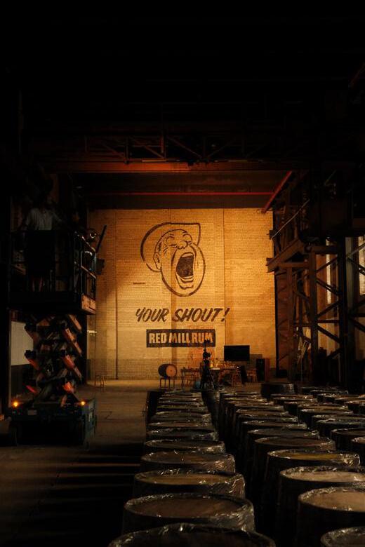
The brief of this project was to transform a heritage warehouse into a mixed-use facility, with a specific focus on integrating a brewery. It involved addressing the challenge of designing spatial layouts that seamlessly merged back-of-house operations with the front of house, enriching the customer tasting experience. The project’s main challenge was incorporating barrel storage racks within a heritage structure, which also needed to serve as a design feature enhancing customer experiences. Careful consideration was given to the flammable nature of alcohol alongside other functions within the building, including a bar with a kitchen, a distillation plant, a woodwork shop, and a lab.
Site Location
Site Image Credits: Atoma Design Pty Ltd Site boundary Robert Street RobertStreet Rober t S t reet Mullens Street MansfieldStreet Parsons S t reet Man sfield Street 169 171 171A175179177 58 60 62 64 66 68 70 2 26 7 75 73 71 67 65 63 5-13 13 55-57 55 53 28 37 White Bay Power Station Bunnings Rozelle 10 26 10-24 White Bay Beer Co. Ro s s e r L a n e Parking
1,500 1,187 FFL +6.920 RL+6.767 (Survey) RL +5.910 (Survey) RL +5.590 (Survey) RL +5.480 (Survey) RL +5.590 (Survey) RL +5.340 (Survey) RL+6.720 (Survey) RL+10.749 FFL +5.840 RL +5.840 FFL +6,920 FFL +6,920 DA-302 1 DA-031 XDP XBC XSC XBC XSC XFHR X DRAIN XBW X DRAIN ROAD SIGN X STAIR 03 (Redundant) UNDERCROFT SITE BOUNDRY XFHR XFE CUR CUR CUR XW 08 Width 4.2m Height approx 5.5m MANSFIELDSTREET CAR PARKING OFF MANSFIELD STREET AT HIGH LEVEL Window above door High LevelHigh LevelHigh LevelHigh Level NOT IN SCOPE OF WORKS (NOT SURVEYED) Exhaust hood Open plan and flexible barrel storage area. Maximum height of barrel storage 5.3m AFFL Sprinklers to be modified to suit barrel storage. Refer to fire services drawings and fire engineering report. Floor Level Change Pass Wash Prep Cleaners FWC MWC ACC WC Store Prep Kitchen New Stairs. To comply with AS1428.1 Store Final Internal configurations including floor levels to be determined at construction certificate stage pending hydraulic advice. Bathrooms population numbers to remain. FE FHR FIP FE FE FE FHR FE FE FE FHR FE FHR Kitchen Exhaust X STORAGE G.02 XCF A:200 m FFL+5.871 CELLAR DOOR RETAIL BAR G.07 XCF A:200 m FFL+5.871 XDP STAIR 04 XD 03 XD 02 XD 01 XW 09 XW 07 XW 06 XW 05 XW 04 XW 03 XW 02 XW 01 XW 10 XW 20 XW 21 XBAL X FIRE EXIT MULLENS STREET FIRE EXIT Exit sign above Door to be amended to made accessible Draft curtain to barrel storage area to underside of sof engineers report and final locations to be determined a CC Draft curtain to barrel storage area to underside of soffit. Refer to fire engineers report and final locations to be determined CC Existing Stair riser and handrail to meet requirements of the BCA AS1428.1-2009. Relocate existing fire hose reels where necessary to be clear of storage racking. New Acoustic Roller Door to replace existing Refer drawing DA-102 for part plan 1200L 1200L BatchTank 1,000 5,400 2,500 5,800 RL +3.873 RL +4.021 RL +4.417 RL +4.640 RL +4.580 RL +4.640 FFL +4.650 FFL +4.750 RL +4.820 RL +4.650 XDP XBC XSC XSC XFHR XELE X DRAIN XBC XSC XBC ROAD SIGN XSTAIR05 X FIRE STAIRCASE 06 Mesh at high level above wall. Mesh at high level above wall. X STAIRS XSC SITE BOUNDRY X UNDERCROFT BEAM OVER D 01 CUR XFE X BEAM OVER CUR Open plan and flexible barrel storage area. Maximum height of barrel storage 5.3m AFFL Sprinklers to be modified to suit barrel storage. Refer to fire services drawings and fire engineering report. Window above door NOT IN SCOPE OF WORKS Parking 01 Parking 02 Parking 03 Parking 04 Parking 05 (Accessible) (Accessible shared area) FE FE FE FE FE FHR FE Width 4.2m Height 4.2m X STORAGE G.03 XCF A:200 m FFL+4.650 X PARTIALLY ENCLOSED ROOM G.06 XCF FFL+4.650 X LOADING ZONE G.04 XCF FFL+4.650 X UNDERCROFT STORAGE G.05 XCF FFL+4.620 5000LPot Boiler 5000LFermenter 5000LBlend Tank 1200L BatchTank 1200L BatchTank X XD 08 XD 09 XW 10 XW 11 XW 12 XW 13 XW 14 XW 15 XW 16 XW 17 X FIRE EXIT MULLENS STREET X FIRE EXIT CHILLER PACK curtain soffit. Refer to fire X FIRE EXIT Refer to Distillery Drawings Management Report Refer to traffic report Existing to be upgraded. Tread riser handrail requirements and AS1428.1-2009. Existing electrical board to comply with BCA. Fire isolated passage as per BCA report Step Ramp 1:10 New perforated roller door to replace existing DISTILLERY G.08 EPX A:140 m FFL+4.700 Refer drawing DA-101 for part plan 11 RL +10.630 m (Survey) RL +13.910m (Survey) RL +18.180m (Survey) RL +22.720 m(Survey) UPPER GROUND LEVEL (+5.840) G.02 Storage G.07 Cellar Door Retail Bar 1,190 Bathrooms ROLLER DOOR XW 06 XW 02 XW 03 XW 04 XW 01 XW 07 XW 08 XW 09 XW 10 XD 01 XD 03 Site boundry X BRICK DETAIL L XD 02 Top of concrete capping as per survey. Top metal roof RL unknown. Shown indicatively only. (Not surveyed) Existing paint work to brick facade to be retained including colourbanding(yellow, orangeandblack) Underside of slab Top parapet as per survey. Underside of undercroft slab MULLENS STREET Level change in plan MANSFIELD STREET XBW TENANCY ABOVE NOT IN SCOPE OF WORKS (NOT SURVEYED) WLWLWLWLWL New Louvre Toilet Exhaust WLWL WL SN02 SN02 SN04 SN02 Fire door to be replaced to increase egress width to comply with AS1428.1 Existing frosted windows amenities area SN01. To Mansfield Street Facade Corner XW 05 SN01SN01 STREET PROPOSED SIGNAGE AND LIGHTING FOR DA 1:100 11 11 RL +13.719m (Survey) UPPER GROUND LEVEL (+5.840) 4,867 G.03 Storage G.04 Loading G.08 Distillery XSC XW 11 XW 12 XW 13 XW 14 XW 15 XW 16 XW 17 XD 04 XSC X BRICK DETAIL 01 XBW Top of wall MULLENS STREET TENANCY ABOVE NOT IN SCOPE OF WORKS (NOT SURVEYED) Proposed fire door WLWLWL WL Alternative location WL Existing window to be replaced with new chiller make up intake air louvres. Existing painted mural on brickwall Existing painted brick work with coloured banding SN01SN01 SN02 WL WL Existing paint work to brick facade to be retained New wall lights to existing brick niches, as indicated Refer drawing DA-202 for part elevation. 11 Documentation Mullens Street Elevation Services coordiantion with facade fenestrations Floor
Spatial
Plan
and services allocation
Visualisations & Detail Documentation

Perspective Barrels Spatial Allocation Section Barrels Spatial Allocation

Perspective Services coordination with exisitng sturcture & distillery equipment
Section Distillery equipment allocation GSPublisherVersion 1607.10.70.95 ACCESS CONSULTANT #Access Consultant Phone: #Access Consultant Phone Email: #Access Consultant E-mail BCA CONSULTANT #BCA Phone: #BCA Phone Number Email: #BCA E-mailEmail: PROJECT MANAGER TBD Projects, Andrew McGaw Phone: +61 407111905 Email: andrew@tpdprojects.com.au DATEREVDESCRIPTION: 29/9/2023 24/11/2023 P01 P04 Preliminary Issue Issue for Consultants Do not scale off drawings. Use figured dimensions only. All dimensions are to be checked on site prior to commencement of work. Report any discrepancies immediately to the architect prior to commencement of work. Allow for adjustments to suit discrepancies. Comply with relevant authorities requirements. Comply with Building Code of Australia requirements. Compl with relevant Australian standards for materials and construction practice. Comply with Basix Certificate. Atoma Design makes no warranties of fitness for any purpose. GENERAL NOTES: These designs, plans, specifications and the copyright therein are the intellectual property of Atoma Design Pty Ltd, and must not be reproduced or copied wholly or in part without written permission of Atoma Design. Rights to this document are subject to payment in ull of all Atoma Designs' fees. This document may only be used for the express purpose for which has been created and any unauthorised use or changes is at the user's sole risk and without limiting Atomas' ights the user releases and indemnifies Atoma from and against all loss so arising. COPYRIGHT: (+4.650) LOWER GROUND FLOOR +13.900) UNDERSIDE OF CONCRETE SOFFIT (+22.720) ROOF Top of Gantry beam RL +10.460m (Survey) RL +5.840m 8,060Check on site Underside of gantry beam 4,233 mm 4,210 Underside of gantry beam Underside of Steel beam RL+13.290m (Survey) 4,450Site measure 5,000Underside of lower soffit (+5.840) UPPER GROUND FLOOR 1,190 +10.550 XW 06 XW 19 X STAIR 03 X STORAGE G.02 XSC XBC XBC Storage for barrels X Beam to steel column Wall overhead Underside of concrete slab TENANCY ABOVE NOT IN SCOPE OF WORKS (NOT SURVEYED) X UNDERCROFT STORAGE G.01 Toilet block with accessible bathroom and storage for cleaner. Designed for capacity of 120 200 patrons. Flexible Configuration. Open plan barrel storage area. Maximum height of barrel storage to the underside gantry rail beam. Sprinklers to be modified to suit barrel storage height and area. Refer to fire services engineering drawings. (+4.650) LOWER GROUND (+13.900) UNDERSIDE OF CONCRETE (+22.720) (+5.840) UPPER GROUND Underside ofPROPOSED SHORT SECTION B 1:100 2(+4.650) LOWER GROUND FLOOR (+13.900) UNDERSIDE OF CONCRETE SOFFIT (+22.720) ROOF Top of Gantry beam RL +10.460m (Survey) RL +5.840m 8,060Check on site Underside of gantry beam 4,233 mm 4,210 Underside of gantry beam Underside of Steel beam RL+13.290m (Survey) 4,450Site measure 5,000Underside of lower soffit (+5.840) UPPER GROUND FLOOR 1,190 +10.550 XW 06 XW 19 X STAIR 03 X STORAGE G.02 XSC XBC XBC Storage for barrels X Beam to steel column Wall overhead Underside of concrete slab TENANCY ABOVE NOT IN SCOPE OF WORKS (NOT SURVEYED) X UNDERCROFT STORAGE G.01 Toilet block with accessible bathroom and storage for cleaner. Designed for a capacity of 120 200 patrons. Flexible Configuration. Open plan barrel storage area. Maximum height of barrel storage to the underside o gantry rail beam. Sprinklers to be modified to suit barrel storage height and area. Refer to fire services engineering drawings. (+4.650) LOWER GROUND FLOOR (+13.900) UNDERSIDE OF CONCRETE SOFFIT (+22.720) ROOF Top of Gantry beam RL+10.460 m (Survey) Underside of Steel Beam RL +13.290m (Survey) 8,140 Underside of Gantry beam 5,423 3,510 Underside of beam RL +8.160m (Survey) 4,100 3,520 3,422 4200 as per site measure RL+4.650m RL +4.750m (+5.840) UPPER GROUND FLOOR 1,190 XBC X brick wall slope outwards XD 08 XW 15 XD 04 X LOADING ZONE G.04 X UNDERCROFT STORAGE G.05 DISTILLERY G.08 Fu ure oca n o d sti ery an pump room sub ect o ure deve o men app ca on approva s. Re e o D sti ery Consu a de a raw ng Proposed oo eve and n sh o b de ermined Underside of concrete slab Distillery Equipment Behind Standard car – 4.91m Small Rigid Vehicle – 6.4m Medium Rigid Vehicle – 8.8m Size of trucks staff parking to be resolved with traffic consultant. X YELLOW GANTRY CRANE TENANCY ABOVE NOT IN SCOPE OF WORKS (NOT SURVEYED) Loca on size and he h o be co rmed on si e 1PROPOSED SHORT SECTION B 1:100 2PROPOSED SHORT SECTION C 1:100 NOTES -Removal -Minor cabinets -Pressure LEGEND Not in scope of works NOTES -All works -All building -All fire -All fire and emergency other fire -All existing penetrations rating, specifically. -All beams -All building by building - All plumbing -Refer -Refer -Check The following -Security -Existing -Rectification -General -Signage -Make-good -Localised -General -Provision -Power -Sprinklers -Smoke -Emergency -Lighting -Statutory -Operational -Fire extinguishers Existing Walls & Structural Columns
The Oculus Commercial
Professional : Atoma Design Role: Graduate Architect
Year : 2022-2023
Location : Surry Hills, Sydney, Australia
Area : 700 sq. m (Restaurant including staff)
Technical Skills Archicad & Twinmotion Adobe Suite
Responsibilities & Contributions : Overall design scheme, documentation, and coordination of services within a multidisciplinary team.
Project Description
This mixed-use precinct combines commercial spaces on the ground floor with hospitality and residential areas on higher levels. The design incorporates green spaces at various levels, providing a natural atmosphere despite being in Sydney’s bustling center.
The restaurant’s concept focuses on indoor and outdoor dining spaces adaptable for any time of day or year, featuring a retractable shading device informed by sun studies called the ‘Oculus’ or eye . To enhance the seasonal ambiance, trees are rotated to reflect each season, creating a dynamic outdoor dining experience that changes with the weather. Seasonal canvases were designed during the project’s conceptual stage to further embody this concept.

Garden in a Restaurant
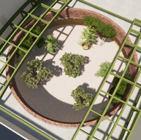
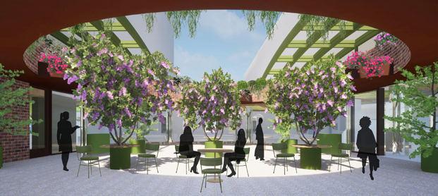
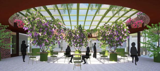
Site Plan Location of restaurant within precinct Retractable Oculus roof for weather protection and acoustic insulation shown in the closed position to enable all year round dining. Restaurant in a Garden - Oculus Roof in open position Outdoor oculus restaurant space, seating surrounded by an abundance of planting at different Retractable Oculus roof for weather protection and acoustic insulation shown in the open position Sliding doors stacked in open position, providing a large opening for indoor / outdoor dining Retractable Oculus roof for weather protection and acoustic insulation shown in the open position.
PROJECT NO : 22004 ATOMA DESIGN Level 3 101-111 William St Darlinghurst NSW 2010 ARCHITECT: Jeremy Courmadias Level 4/17-19 Brisbane St Surry Hills NSW 2010 2-38 Baptist Street, 397-399 Cleveland Street, Redfern 2016. www.atomdesign.com.au0411 797 669 belinda@atomadesign.com.au N A-0001 COVER PAGE WUNDERLICH ABN: 61 612 588 977 ISSUE 17/1/2023 Scale 1:1 @A3 GENERAL INFORMATION DRAWINGS No. A-0001 A-002 A-101 A-102 A-102 A-121 A-131 A-201 A-202 A-301 A-302 A-321 A-511 A-521 A-531 A-571 A-571 A-572 A-573 NAME COVER PAGE SITE PLAN EXISITNG FLOOR PLAN RESTAURANT FURNITURE LAYOUT RESTAURANT SETOUT PLAN BASEMENT 02 PLAN BASEMENT 03 PLAN RESTAURANT RCP RESTAURANT RCP SERVICES OCULUS GARDEN SECTIONS INTERNAL FITOUT SECTIONS THRESHOLD SECTIONS DRINKS BAR PLAN KITCHEN DINING BENCH PLAN HOTEL CORRIDOR SEATING PLAN OUTDOOR TABLE & PLANTER SCHEDULE OUTDOOR TABLE & PLANTER SCHEDULE INDOOR TABLE & PLANTER SCHEDULE CHAIR SCHEDULE SCALE 1:1 1:200 1:100 1:100 1:100 1:100 1:100 1:100 1:50 1:50 1:50 1:50 1:50 1:50 REV O cu lu s Re stau r a n t Te n a n cy Fir st Floo r , L11 4L 1 1 5 23 8 B a p tist S tre e t, 39 73 9 9 Cle ve la n d S tre e t, Red fer n PLANDRAWING LISTLOCATION Planting at different levels.
Floor Plan
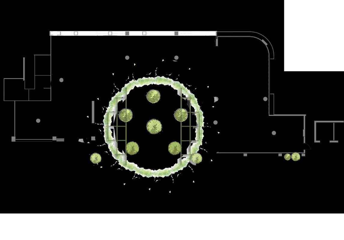
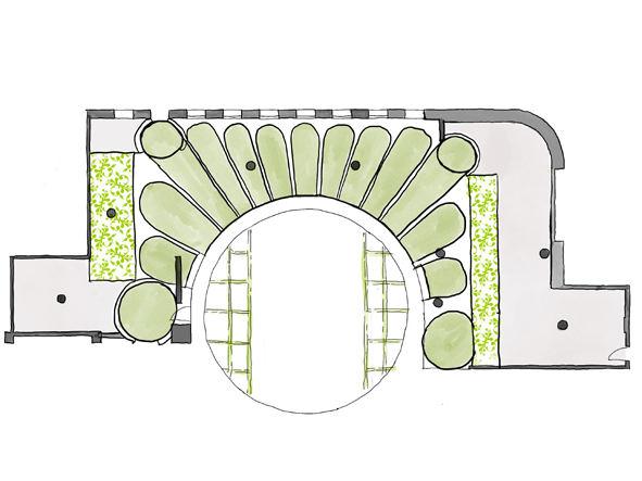
GSPublisherVersion 1456.5.33.95 1 4 6 8 7 3 2 3 11 4 5 9 10 11 12 13 14 PROJECT NO 22004 PROJECT:CLIENT:DATE:REV:ISSUE: ATOMA DESIGN Level 3 101-111 William St Darlinghurst NSW 2010 ARCHITECT: Jeremy Courmadias Level 4/17-19 Brisbane St Surry Hills NSW 2010 2-38 Baptist Street, 397-399 Cleveland Street, Redfern 2016. www.atomdesign.com.au 0411 797 669 belinda@atomadesign.com.au N Do not scale off drawings. Use figured dimensions only. All dimensions are to be checked on site. Report any discrepancies immediately to the architect. These designs, plans, speci fications and the copyright therein are the property of atoma design, and must not be reproduced or copied wholly or in part without written permission of atoma design. SK01 SITE PLAN WUNDERLICH NOTES: ABN: 61 612 588 977 ISSUE 21/6/2023 A Scale 1:200 @A3 CONCEPT DESIGN S3S4 LIFT G1 5 1. Outdoor oculus restaurant garden space, seating surrounded by planting. 2. High level planting above Oculus Space 3. Retractable Oculus roof for weather protection and acoustic insulation. 4. Sliding doors stacked in open position, providing an indoor / outdoor connection 5. Low level circular banquettes, with views out to Oculus garden space, with forms radiating from the center of the Oculus 6. Cloister seating, intimate seating framed by the arched windows of the hotel cloister 7. Semi private dining 8. Hotel entrance, access to bathrooms 9. Bar with arched ceiling 10. Cool room & Storage Area 11. Maitre’d Areas 12. Open kitchen with wood fire oven 13. Restaurant Bathrooms 14. Lifts to Basements Concept
Sketch Design to DetailingSketch Design to Detailing Planter DetailsCeiling
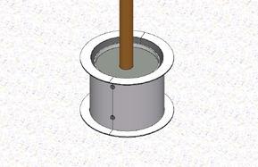
Seasonal tree
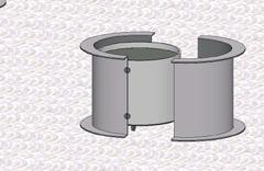
Removable table top with hole for tree trunk
Fixings to underside of shroud (top flange) for removable top
Aluminium powdercoated shroud, in two half semicircles with top and bottom flanges, packed at bottom to suit falls
Removable table top with hole for tree truck.
Fixings to underside of shroud (top flange) for removable top.
Fixings to underside of shroud (top flange) for removable top.
Pot from nursery, on wheels, with adjustable base for falls.
Latch clamp to underside of planter to close shut.
Latch clamp to underside of planter to close shut.
Aluminium powdercoated shroud, in two half semicircles with top and bottom flanges, packed at bottom to suit falls.
Aluminium powdercoated shroud, in two half semicircles with top and bottom flanges, packed at bottom to suit falls.
Fixings to bottom flange of shroud, into pavers / slab to fix in place
Pressed metal cladding directly mechanically fixed to a plywood substrate aluminium shroud.
Pressed metal cladding directly mechanically fixed to a plywood substrate aluminium shroud.
Drainage in base of pot and pavers / slab
Pot from nursery, on wheels, with adjustable base for falls.
Hinge on one side.
Pot from nursery, on wheels, with adjustable base for falls.
Hinge on one side.
Self supporting bottom flange of shroud from 6mm thick aluminium with self weight.
Base building slab, screed and pavers, with falls for drainage
Self supporting bottom flange of shroud from 6mm thick aluminium with self weight.
Provide packers for underside of bottom flange of shroud.
Provide packers for underside of bottom flange of shroud.
Base of pot plant to be lifted and replaced with pallet jack. To be developed further with landscape consultant.
Base of pot plant to be lifted and replaced with pallet jack. To be developed further with landscape consultant.
Base of pot with central drainage hole and in pavers/slab.
Base of pot with central drainage hole and in pavers/slab.
Base building slab, screed and pavers with falls for drainage.
Base building slab, screed and pavers with falls for drainage.

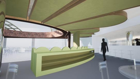
Ceiling Concept
1. Organic petal canopy, timber and fabric
2. Pressed metal curved canopy
3. Oculus outdoor retractable roof, in open position
4. Oculus outdoor ceiling
5. Back of house plasterboard ceilng
6. Open to sky, when roof is open

7. Services in between petals
PROJECT:CLIENT:DATE:REV:ISSUE: ATOMA DESIGN Level 3 101-111 William St Darlinghurst NSW 2010 ARCHITECT: Jeremy Courmadias Level 4/17-19 Brisbane St Surry Hills NSW 2010 2-38 Baptist Street, 397-399 Cleveland Street, Redfern 2016. www.atomdesign.com.au 16.03.23AOculus Planter Setout Do not scale off drawings. Use figured dimensions only. All dimensions are to be checked on site. Report any discrepancies immediately to the architect. These designs, plans, speci fications and the copyright therein are the property of atoma design, and must not be reproduced or copied A-402 PLANTER DETAIL WUNDERLICH NOTES: ABN: 61 612 588 977 100800100 1,000 PLANTER WITHOUT TABLETOP 1:10 2TYPICAL PLANTER WITH TABLETOP Base building slab, screed and pavers with falls for drainage. Base of pot with central drainage hole and in pavers/slab. Base of pot plant to be lifted and replaced with
To be developed further with landscape
PLANTER SCHEDULE A-603REFER TO PLANTER SCH EDULE A-603 PROJECT:CLIENT:DATE:REV:ISSUE: ATOMA DESIGN Level 3 101-111 William St Darlinghurst NSW 2010 ARCHITECT: Jeremy Courmadias Level 4/17-19 Brisbane St Surry Hills NSW 2010 2-38 Baptist Street, 397-399 Cleveland Street, Redfern 2016. www.atomdesign.com.au 16.03.23AOculus Planter Setout drawings. Use figured dimensions are to be Report any discrepancies architect. These designs, and the copyright property of atoma design, reproduced or copied A-402 PLANTER DETAIL WUNDERLICH ABN: 61 612 588 977 PRELIMINARY ISSUE 16/5/2023 100800100 1,000 1:10 2TYPICAL PLANTER WITH TABLETOP Seasonal Tree
pallet jack.
consultant.
A-603REFER TO PLANTER SCH EDULE A-603 ATOMA DESIGN Level 3 101-111 William St Darlinghurst NSW 2010 ARCHITECT: Jeremy Courmadias Level 4/17-19 Brisbane St Surry Hills NSW 2010 2-38 Baptist Street, 397-399 Cleveland Street, Redfern 2016. www.atomdesign.com.au 16.03.23AOculus Planter Setout A-402 PLANTER DETAIL WUNDERLICH ABN: 61 612 588 977 PRELIMINARY ISSUE 16/5/2023 100800100 1:10 2TYPICAL PLANTER WITH TABLETOP
Seasonal Tree
Removable table top with hole for tree truck.
A-603REFER TO PLANTER SCH EDULE A-603 Ceiling Concept 1. Organic petal canopy, timber and fabric 2. Pressed metal curved canopy 1 2 33 4 5 6 7
Planter Detail incorporated with furniture Plants to be swapped out seasonally. Organic Petal ceiling
Design
Three Layers Residential
Professional : Atoma Design
Role: Graduate of Architecture
Year : 2024-Current
Location : Abbotsford, Sydney, NSW
Software Skills: Archicad
Responsibilities :
Engaged in concept design, design development, and conducted regular site visits as part of the project team.
Project Description
The project’s aim was to redesign the house’s spatial layout to accommodate the changing needs of an aging couple and a growing family. The existing layout was outdated and no longer met the family’s requirements.
The team addressed this challenge by maximizing space utilization, including adding a lower ground level under the house to create more room. They also extended the rear footprint to create a spacious kitchen, dining, and living area for family gatherings. Additionally, upper-level bedrooms were enhanced with walk-in closets and en-suites. Crucially, the house was future-proofed by ensuring wheelchair accessibility, incorporating AS1428.1 standards, and installing a lift for easy access to multiple levels in the future.
Short Section
East Elevation
GSPublisherVersion 1717.12.84.95 DRAWING SCALE ATOMA DESIGN PTY LTD Level 3 101-111 William St Darlinghurst NSW 2010 0411 797 669 belinda@atomadesign.com.au ARCHITECT: CLIENT: ALISON BONANNO 11 Marmion Road, Abbotsford PROJECT NO. 11 Marmion Road, Abbotsford. Sydney NSW 2009 Australia ADDRESS PROJECT PRELIMINARY STATUS Wor k i n Pr o g r ess DATEREVDESCRIPTION: Work in Progress 01 WIP Preliminary Issue SECTIONS GENERAL NOTES: COPYRIGHT: A-202 ABN: 61 612 588 977 MARMION ROAD 24001 Do not scale off drawings. Use figured dimensions only. All dimensions are to be checked on site prio to commencement of work. Report any discrepancies immediately to the architect prior to commencement of work. Allow for adjustments to suit discrepancies. Comply with relevant authorities requirements. Comply with Building Code of Australia requirements Comply with relevant Australian standards for materials and construction practice. Comply with Basix Certificate. Atoma Design makes no warranties of fitness for any purpose. These designs, plans, specifications and the copyright therein are the intellectual property of Atoma Design Pty Ltd, and must not be reproduced or copied wholly or in part without written permission of Atoma Design. Rights to this document are subject to payment in ull of all Atoma Designs' fees. This document may only be used for the express purpose for which it has been created and any unauthorised se or changes is at the user's sole risk and without limiting Atomas' right the user releases and indemnifies Atoma from and agains all loss so arising. Belinda Pajkovic NSW Registration #9786 NOMINATED ARCHITECT: Scale 1:50 BDY. BDY. 1SECTION BB 1:50 NOTE This drawing has not been updated. They are meant for reference only. W 01 W 02
TURF GARDEN TURF GARDEN PAVED PAVED SPA TURF GARDEN PUMP STAIR 1 GARDEN PATH MARMION ROAD TOP CHIMNEY RL 29.86 RIDGE 28.84 R D G E 28.54 G UT T ER 28.13 RIDGE 29.10 RIDGE 32.30 G 30.32 WINDOW H 26.24 S 25.25 WINDOW H 26.75 S 25.53 GUTTER 26.93 GUTTER 30.20 WINDOW H 26.75 S 25.53 WINDOW H 30.06 S 27.27 RIDGE 31.77 RIDGE 27.89 WINDOW H 26.69 S 25.03 GUTTER 27.55 RIDGE 29.27 RIDGE 32.30 VERANDAH 24.07 GUTTER 26.88 LAYBACK TOP KERB TOP CHIMNEY RL 30.39 RIDGE 29.11 GUTTER 26.52 COG 27.61 RIDGE 26.16 RIDGE 27.60 WINDOW H 26.72 GUTTER 26.86 RIDGE 27.75 WINDOW H 26.83 S 25.22 WINDOW H 26.83 S 25.22 GG 27.19 WINDOW H 26.83 S 25.39 TOP CHIMNEY RL 30.40 RIDGE 30.45 PALM 0.15D 5H 4S T OP K E RB POOL BRICK GARAGE No 9 ONE & TWO STOREY BRICK COTTAGE SLATE & METAL ROOF BRICK GARAGE VERANDAH No 13 BRICK COTTAGE TILE & METAL ROOF AWNING CONCRETE PATH 3° 18' 20" 45.72 183° 18 20" 45.72 273° 18' 20" 15.24 93 18' 20" 15.24 BOARD SHED METAL ROOF BT 25.25 25.20 25.21 25.24 25.28 25.29 25.22 25.16 25.24 25.25 25.08 22.35 21.69 21.68 20.33 21.53 21.38 22.73 22.74 22.95 21.95 21.73 21.63 22.01 22.41 24.22 24.19 24.18 22.34 22.55 22.19 22.14 21.65 19.94 ATC 19.94 20.03 22.68 22.65 21.55 21.56 21.39 20.51 21.47 21.55 20.52 20.38 A TC 20.38 20.28 20.16 20.18 20.10 23.36 23.08 22.97 23.52 23.93 24.25 24.26 24.27 24.30 24.40 24.46 24.22 24.24 24.23 24.29 24.29 24.32 24.29 24.42 24.47 24.58 24.59 24.63 24.61 24.22 22.83 23.30 23.36 23.43 23.62 23.85 24.58 24.63 24.58 24.63 24.67 20.01 21.63 24.67 24.71 24.75 24.81 24.95 24.97 25.04 24.00 24.71 24.76 24.82 24.80 24.82 24.95 24.95 24.96 24.83 24.81 24.82 24.96 24.98 24.98 24.96 25.08 25.08 25.08 25.08 25.08 25.04 25.09 25.08 25.09 25.04 25.25 25.25 25.24 25.24 25.25 25.25 25.24 25.24 1 1 25.1 1 20.12 19.98 20.01 20.36 20.28 20.31 ELP 20.14 20.12 20.29 19.80 19.78 19.86 19.73 19.82 19.83 RL2006(A.H.D.) 20.31 MANHOLE BMNAILINKERB + FGL 23.36? + FFL 25.04 +TOW 23.41 + FFL 20.18 + FFL 23.11 FFL 21.49 B B C C D D 11 33 44 A A 22 Documentation Site Plan
Documentation DRAWING SCALE ATOMA DESIGN PTY LTD Level 3 101-111 William St Darlinghurst NSW 2010 ARCHITECT: CLIENT: ALISON BONANNO 11 Marmion Road, Abbotsford PROJECT NO. PROJECT DRAWN BYCHECKED DATEREVDESCRIPTION: Ground Floor GENERAL NOTES: COPYRIGHT: SK02 ABN: 61 612 588 977 MARMION ROAD LEVEL 1 PLAN ISSUE 19/4/2024 Do not scale off drawings. Use figured dimensions only. All dimensions are to be checked on site prior to commencement of work. Report any discrepancies immediately to the architect prior to commencement of work. Allow for adjustments to suit discrepancies. These designs, plans, specifications and the copyright therein are the intellectual property of Atoma Design Pty Ltd, and must not be reproduced or copied wholly or in part without written permission of Atoma Design. Rights to this document are subject to payment in ull of ST-3B ST-3 CPT-1 CH 2,650 ST-5 ST-4 CH 3300 + FFL 24.33 TURF GARDEN TURF GARDEN GARDEN TURF STAIR 1 GARDEN + FFL 24.30 KITCHEN POWDER ST-1 LAUNDRY ENS 4 ST-2 HOUSEKEEPER TF-1 HALL 1 ENTRY ST-3 BBQ VERANDAH 2 + FFL 24.30 10. EXIST. STAIR STAIR 2 + FFL 24.33 ST-1 + FFL 20.18 + FFL 24.19 + FFL 23.11 MARMION ROAD 21.55 21.56 NEW SANDSTONE ENTRY STAIR + FFL 24.19 SD. SD. SD. 15. VERANDAH +TOW 23.41 + FFL 21.49 + FGL 23.26 NEW METAL RAILING 15. 18.22. 23. 16. 17. 20. 1.2M POOL FENCE & GATE ST-1 SUBSOIL DRAINAGE REQ'D OVER MEMBRANE + FGL 23.36 SW. SW ROOF OVER SANDSTONE CLADDING FINISH TO BLOCK WALLS SW. EXIST. TILE EXIST. TILE SANDSTONE CLADDING FINISH TO BLOCK WALLS 1.2. 1. 2. 2. 1. GAS. 740 TBC Wardrobe 8,680 COS Kitchen & scullery 1,360 COS 1,807 COS 2,230 2200 As per site 4,215 Laundry 4,190 Scullery 1,800 1780 as per site Housekeepers' Ensite 9,220 9215 as per site measure 1,900 2280 as per site 4,200 Housekeeper 4,910 Living Bel to review door. WINDOW BLOCK OFF WINDOW BLOCK OFF WINDOW ST-3 FORMAL DINING TF-1 SCULLERY FAMILY TF-1 LIVING ST-3 ST-3 ST-4 ST-4 CH 3300 CH 3300 + FFL 24.33 + FFL 24.33 Queen Bed 11 44 D D B B C C A A 33 4PROPOSED GROUND FLOOR 2024 - PRESENTATION 1:100 Ground Floor Plan
The Four Units
Residential Renovation Dukes Workshop
Professional Role: Graduate of Architecture
Year : 2021-2022
Location : Cox Avenue, Bondi, NSW
Software Skills: Archicad
Responsibilities : Design schemes involving digital massing, sun study and visualization, understanding of council codes and restrictions.
Other Contributions : All documentation from DD to DA stage.
Project Description
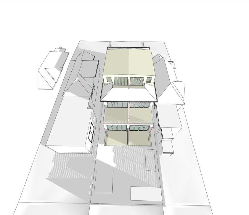
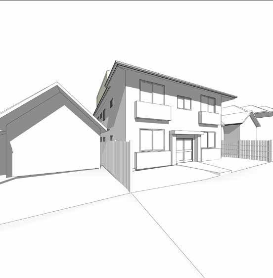
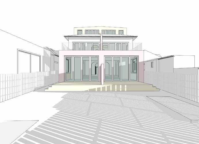
This project comprised of 4 apartments (units) owned by three different clients, each wanting to maximize their internal usable space to achieve the most from the prime location of their property. The challenge involved visualizing the maximum achievable additional space that can be equitably added to each unit without overshadowing the neighbors and maintain the council height restrictions.
The solution involved the bottom units to partially extend into the backyard in the form of an external deck and a light weight sun room to maximize the sun from the south. This resulted in adding an extra bedroom and a now larger & usable living space within the units. The upper units
12 Cox Avenue BONDI 402 New South Head Road DOUBLE BAY 2028 Ph 02 9328 9944 Fax 02 9328 9844 Sketch Perspective View from Cox Avenue View from Backyard- South East Proposed GSPublisherVersion 0.98.100.100
View from Backyard

Site
Site Analysis Plan Date: 5/06/2022 Scale: 12 Cox Avenue, BONDI 402 New South Head Road, DOUBLE BAY 2028 Ph: 02 9328 9944 Fax: 02 9328 9844 Option 1 Site Analysis 10 cox avenue 12 32 39 RR 3 PAVED TIMBER SHED 1 2 .1 9 1 2 .1 88 36 .57 5 29 56 TG 27 32 TG 29 56 RR 28 79 RR 30 65 TG two storey brick residence 14 single storey brick residence two storey brick residence site area 445 8 m2 36 .57 5 8 16 SP 17191 R.L 23 51 R.L 23 16 R.L 22 06 PAVED 29.38 TG 28 97 RR garden terrace first floor balcony ground floor terrace 29.38 TG 29 56 TG garbage bins Site Analysis Plan
Documentation
Analysis
12 Cox Avenue, BONDI 402 New South Head Road, DOUBLE BAY 2028 Ph: 02 9328 9944 Fax: 02 9328 9844 Option 1 Elevations 1,010 8,500 3,150 5,660 Boundary RL 29 56 TOG RL 29 38 TOG RL 26 73 first floor RL 23 58 ground floor RL 32 289 proposed roof RL 29 38 attic RL 32 39 existing roof M HEIGHT LIMIT 14 3,150 5,660 Boundary Boundary RL 32 39 R.H. RL 29 56 TOG RL 25 73 TOG RL 28 79 RH RL 26 02 TOG RL 24 50 TOG RL 27 23 RH RL 29 56 RH RL 28 90 RH 14 10 RL 26 73 first floor RL 23 58 ground floor RL 32 289 proposed roof RL 29 38 attic RL 32 39 existing roof NON COMPIANCE 8.5 M HEIGHT LIMIT North
East Elevation GSPublisherVersion 0.95.100.48 Page size A3 Revision Project No.Drawing No. Checked By Status Date: 5/06/2022 Scale: 2012 12 Cox Avenue, BONDI 402 New South Head Road, DOUBLE BAY 2028 Ph: 02 9328 9944 Fax: 02 9328 9844 04 Option 1 AD A Attic 01 SK 150 4,671 230 4,671 150 2,670 3,8554,360 7,554 6,5251504,210150 1,1505,475 912 9,872 1,405 s torag e s torag e b ed ro o m b ed ro o m g ard en terrac e g ard en terrac e D A A C C DB B Attic Plan Page size A3 Revision Project No.Drawing No. Checked By Status Date: 5/06/2022 Scale: 2012 12 Cox Avenue, BONDI 402 New South Head Road, DOUBLE BAY 2028 Ph: 02 9328 9944 Fax: 02 9328 9844 03 Option 1 AD A First Foor 01 SK 900 3,911 250 3,911 9,872 5,475 150 1,000 1,730 140 1,790 140 700 5,835 300 3,081 700 20,169 3,781 900 existing bed room l ving sun room existing bed room l ving sun room bathroom A C UPUP study k tchen study bathroom k tchen terrace terrace D F P store store B F P 3 4 First
Attic
East Elevation Attic Isometric
Elevation
Floor Plan Documentation Attic Addition
Floor Plan
Dudley House
Residential Renovation Dukes Workshop
Professional Role: Graduate of Architecture
Year : 2021-2022
Location : Dudley Road, Rosebay, NSW
Software Skills: Archicad
Responsibilities : Measuring and documenting existing building, design schemes involving digital massing, creating various project schedules.
Other Contributions : All documentation from DD to DA stage.
Project Description
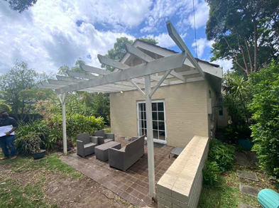
Interior renovation and kitchen extension from design concept to development application stage. This project involved extensive measurements on site to develop an accurate BIM existing model which was further used to produced proposed design concepts. The kitchen extension required accurate location of adjacent trees and existing structural systems to integrate the proposed structural amendments.

Exisitng West Elevation 2D Project No Drawing No Checked By Status Date 15 10 2021 Scale 1:100 15, Dudley Road Rose Bay, NSW 402 New South Head Road DOUBLE BAY 2028 Ph: 02 9328 9944 Fax: 02 9328 9844 Exisitng 00 EXISITNG AD North & East Elevation 1,5001,2203,180 RIDGE 62 67 RIDGE 61 83 RIDGE 60 88 CHIM 60 88 TG 59 48 TG 58 RIDGE 62 67 RIDGE 61 83 RIDGE 60 88 CHIM 60 88 TG 58 43 TG 58 90 TG 59 48 TG 58 89 55 90 L 54.40 West Elevation
54 Exisitng West Elevation Site Picture 55
East Elevaton

Site Analysis Plan 15, Dudley Road Rose Bay, NSW 402 New South Head Road DOUBLE BAY 2028 Ph 02 9328 9944 Fax: 02 9328 9844 Proposed Site Analysis Plan REVISION NOTES Revisions are shown in orange RFI's are shown in green All dimensions checked on site NOT FOR CONSTRUCTION: DESIGN DEVELOPMENT ONLY ABBREVIATIONS CTR - centre line MATERIALS KEY exisitng new brickwork timber glass stee balustrade timber decking bathroom tiles pervious paving new tile on exisitng slab level grass brickwork to be demolished concrete to be demolished new timber timber to be demolished concrete or stone timber joinery COMMENTS site analysis plan 1 2 3 4 5 6 7 R L 54 86 R L 57 30 R L 55 95 R L 56 01 R L 55 92 1 2 3 4 5 6 7 boundary boundary 1,282 4,690 17 dudley road 15 45. 72 DP 6298 SEC E 11 62 67 R R 13 front garden 45. 72 15 24 e xi stin g d ri ve w a y 61 83 R R 60 88 R R 58 89 T G 59 48 T G p o o 1-2 STOREY BRICK HOUSE SITE AREA 696 7 m 2 e xi stin g sl a b b e l o w 15 24 COURTENAY ROAD 12 18 58 90 T G 58 43 T G R L 56 30 R L 5 3 18 R L 5 3 08 R L 5 5 31 R L 57 18 16 1-2 STOREY BRICK HOUSE 1-2 STOREY BRICK HOUSE rear garden terrace northern side garden rear deck pool area southern side garden existing pergola f a l stri p d ra n n e w a n d n g R L 5 5 .46 58 43 T G 56 s DEVELOPMENT slab demolished 57
Documentation Site Analysis
Documentation
ALLOWANCES:
GSPublisherVersion 0.90.100.52 15, Dudley Road Rose Bay, NSW Page size A3 Revision Project No Drawing No Checked By: Status: Date 15 10/2021 Scale 2012 402 New South Head Road DOUBLE BAY 2028 Ph 02 9328 9944 Fax: 02 9328 9844 PR 05 Proposed AD E South & West Elevations Revisions are shown in orange RFI's are shown in green All dimensions checked on site NOT FOR CONSTRUCTION: DESIGN DEVELOPMENT ONLY ABBREVIATIONS CTR - centre line MATERIALS KEY exisitng new brickwork timber glass stee balustrade timber decking bathroom tiles pervious paving new tile on exisitng slab level grass PRICING brickwork to be demolished concrete to be demolished new timber timber to be demolished concrete or stone timber joinery COMMENTS NEW OPENING FOR MASTER ENSUITE ALLOWANCE FOR JULIETTE BALCONY RELOCATE RENNAI HW UNIT PROPOSED POSITION FOR NEW AIRCON W08 RIDGE 62 67 RIDGE 61 83 RIDGE 60 88 HT 58 69 rear deck new skylight new skylight TG 58 89 UGF R.L 57 06 GF R.L 55 90 LGF R.L 54.40 pool TG 59 48 W09 D07 D08 W06 D05 D06 RIDGE 62 67 TG 59 48 TG 58 89 Boundary Boundary UGF R.L 57 06 GF R.L 55 90 LGF R.L 54.40 1:100 south elevation west elevation NOTES
ELEVATION
EXISTING PLUMBING
RENNAI INSTANTANIOUS NEW AC VRV 2 BEDROOMS 2 NEW SKYLIGHTS 2 JULIETTE BALCONIES HANDRAILS NEW TIMBER DECK HARD LANDSCAPING STORMWATER LIGHTING REVISION NOTES Revisions are shown in orange RFI's are shown in green All dimensions checked on site NOT FOR CONSTRUCTION DESIGN DEVELOPMENT ONLY ABBREVIATIONS CTR - centre line MATERIALS KEY exisitng new brickwork timber glass stee balustrade timber decking bathroom tiles pervious paving new tile on exisitng slab level grass brickwork to be demolished concrete to be demolished new timber timber to be demolished concrete or stone timber joinery COMMENTS RIDGE 62 67 RIDGE 61 83 RIDGE 60 88 new skylight new skylight TG 59 48 W09 D07 D08 W06 D05 D06 RIDGE 62 67 TG 59 48 TG 58 89 Boundary Boundary UGF R.L 57 06 GF R.L 55 90 LGF R.L 54.40 south elevation
ALLOWANCES: SOUTH
TERMINATE
RELOCATE
NOTES
SOUTH ELEVATION TERMINATE EXISTING PLUMBING RELOCATE RENNAI INSTANTANIOUS NEW AC VRV 2 BEDROOMS 2 NEW SKYLIGHTS 2 JULIETTE BALCONIES HANDRAILS NEW TIMBER DECK HARD LANDSCAPING STORMWATER LIGHTING Short Section Proposed 1,1901,160 4,150 2,660 1,5001,160 1,800 hallway kitchen study RIDGE 62 67 Boundary Boundary first floor hallway drawing room ground floor hallway existing pargola entry library RIDGE 60. 88 RIDGE 61. 83 RIDGE 62. 67 D05D01 2,490 section B-B section A-A 59 15, Dudley Road Rose Bay, NSW Checked By Status Date: 15/10 2021 Scale: 402 New South Head Road, DOUBLE BAY 2028 Ph 02 9328 9944 Fax 02 9328 9844 Proposed AD South & West Elevations REVISION NOTES Revisions are shown in orange RFI's are shown in green All dimensions checked on site NOT FOR CONSTRUCTION: DESIGN DEVELOPMENT ONLY ABBREVIATIONS CTR - centre line MATERIALS KEY exisitng new brickwork timber glass steel balustrade timber decking bathroom tiles pervious paving new tile on exisitng slab level grass PRICING brickwork to be demolished concrete to be demolished new timber timber to be demolished concrete or stone timber joinery COMMENTS NEW OPENING FOR MASTER ENSUITE ALLOWANCE FOR JULIETTE BALCONY RELOCATE RENNAI HW UNIT PROPOSED POSITION FOR NEW AIRCON W08 RIDGE 62 67 RIDGE 61 83 RIDGE 60 88 HT 58 69 rear deck new skylight new skylight TG 58 89 UGF R.L 57 06 GF R.L 55 90 LGF R.L 54.40 pool TG 59 48 W09 D07 D08 W06 D05 D06 RIDGE 62 67 TG 59 48 TG 58 89 Boundary Boundary UGF R.L 57 06 GF R.L 55 90 LGF R.L 54.40 1:100 south elevation west elevation NOTES
SOUTH ELEVATION
EXISTING PLUMBING
RENNAI
NEW AC VRV 2 BEDROOMS 2 NEW SKYLIGHTS 2 JULIETTE BALCONIES
TIMBER DECK HARD LANDSCAPING STORMWATER LIGHTING CONSTRUCTION e 58 L 1:1 South Elevation Proposed West Elevation Proposed
ALLOWANCES:
TERMINATE
RELOCATE
INSTANTANIOUS
HANDRAILS NEW
Elevation &
58
Section
Dichotomous House
High-end Residential
Professional (Under Construction) r+d studio
Role:Architect (Project Lead)|Group (2-3)|Architecture
Year : 2018-2019
Location : Vasant Kinj, New Delhi, India
Site Area : 2 Ha, Built Up: 1400 sq. m
Technical Skills
Design Resolution: Archicad & Rhino
Drawing Production: Archicad & Autocad
Presenation & Rendering: Adobe Suite
Responsibilities : Overseeing the project from Concept to Tender and construction on site.
Other Contributions : Coordination with various stakeholders and attending regular meeting with clients.
Project Description
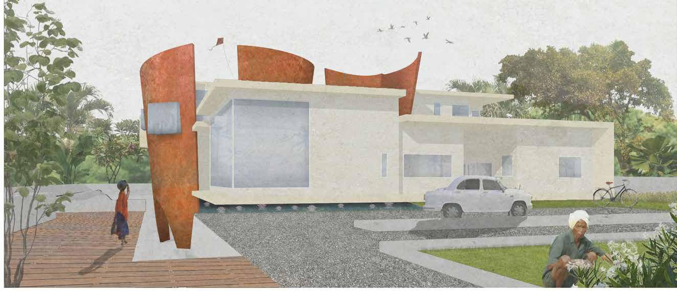
Designed for a family of two couples- elderly and young, this residence is a binary of their spirits. It is a coalesce of two contrasting elements in form, materiality and spaces. The form is a composition of straight clean lines interrupted by quirky curves which evoke a sense of eccentricity in a stable geometry. The ground floor caters to the social spaces while the upper floor the private. A basement with sunken garden creates room for recreational spaces. The juxtaposition flows in materials also with corten steel having a rustic appearance sitting with white stucco finish. The architecture exudes emotions from two ends of the spectrum for its users from sombre to exciting as they move between the son’s wing and father’s wing or from the basement to the first floor.
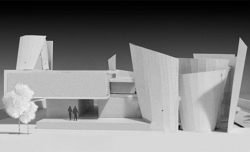
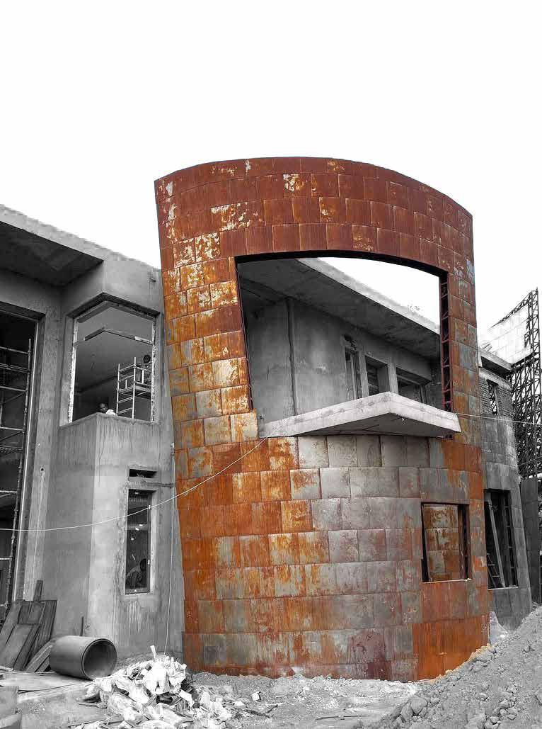
Physical Model of Funicular Arches Facade Development- South Elevation Picture Credits : r plus d Studio

Option 04 Rounded Offset Arches (Selected) Shape Development
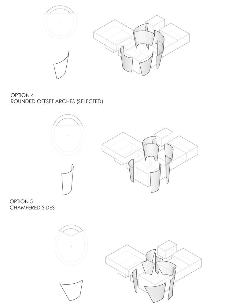
Option 01 Straight Extrusion
Option 05 Chamfered Sides
Option 02 Intersecting Arches
Design Exploration Funicular Arches Stage 01 Option 03 Offset Arches
Stage 02-Position Exploration
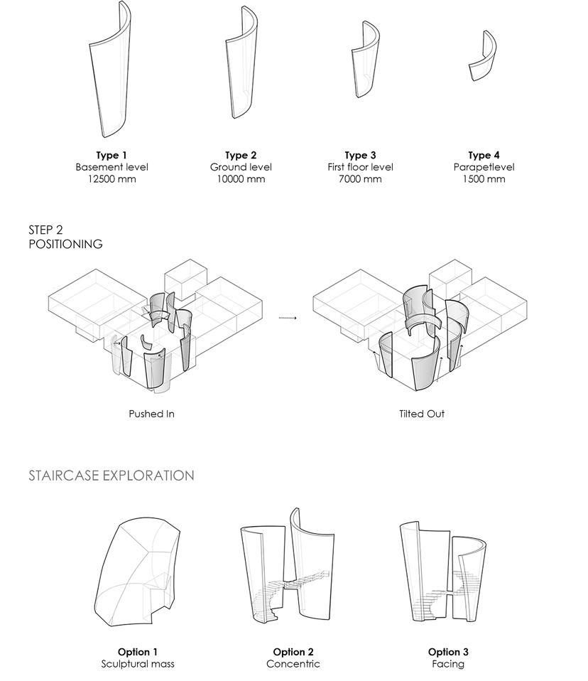

Step 01 Types of Fins Step 02 Positioning Staircase Exploration
Design Exploration Funicular Arches
Wall Section with Funicular Arch


Elevation
Documentation
Exploration
Material Exploration
Silver Fins with White Finish (Walls)
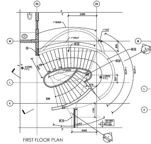
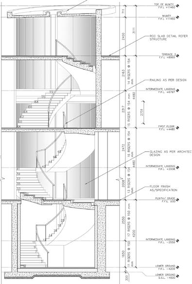

Site Image Courtesy r+d studio Documentation Staircase
Staircase Section
First Floor Plan
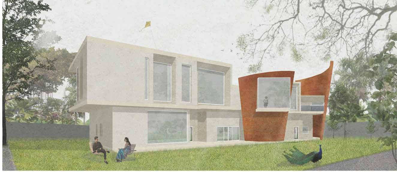
South Elevation
Entrance
South View School
Institutional Project
Professional (Built) r+d studio
Role:Architect|Group (2-3)|Interior
Year : 2017-2018
Location : Remraam, Dubai
Built Up: 5830 sq.m
Technical skills: Autocad, Adobe Photoshop, Hand Sketching
Responsibilities : Designing reflected ceiling plans and coordinating the design with MEP. Other Contributions : Designing interior elevation, furniture and flooring patterns of selected spaces, coordinating the visualization of renders.
Project Description
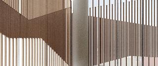
The interior concept is based on the arid and sandy landscape of Dubai by representing Sand Dunes The free form and granulated texture can be seen as a constant theme throughout the spaces within the school. For instance the undulating wooden baffled ceiling of the Junior Library, the use of wavy forms in the fin designed walls of the Reception
Thematic colors highlight the use of large public spaces and introduce a unique twist of energy to the otherwise mellow Dubai landscape. For instance lime green in the acoustic paneling of the Junior Multipurpose Hall, a combination of green and blue to the triangulated baffle ceiling of the Canteen

K-12
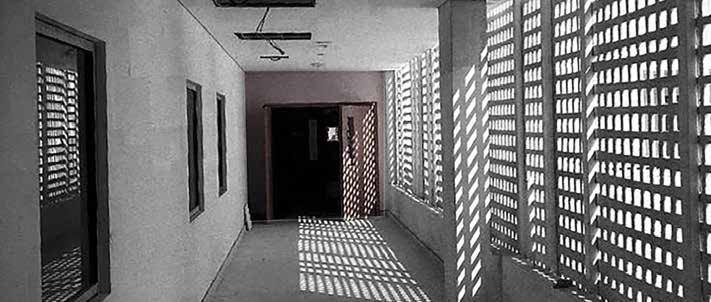
Site Image: Interior Walkway
Picture
Credits: r+d studio Built: Junior Library Picture Credits: South View School, Dubai & r + d studio, India
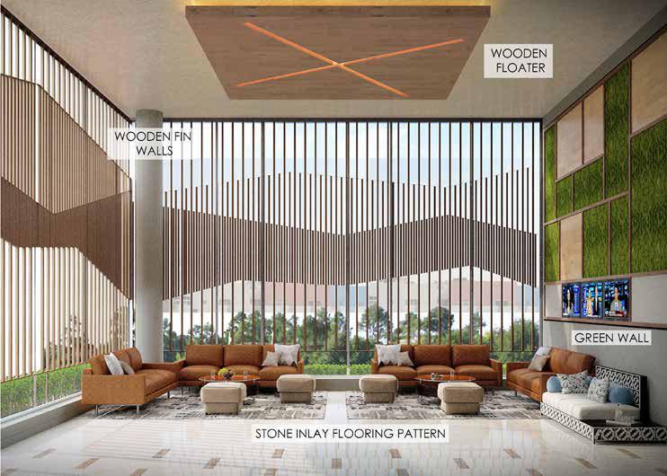

Admin Reception
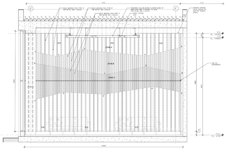
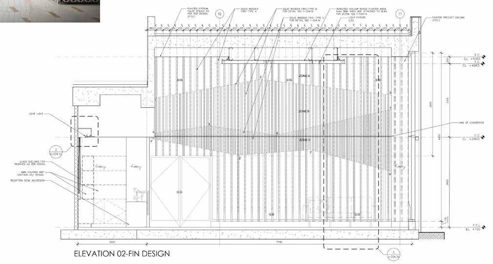
Documentation & Construction
Photo Wooden Fin Wall
02 Fin Design
Rendered Visualization Site
Elevation
Elevation 01 Fin Design


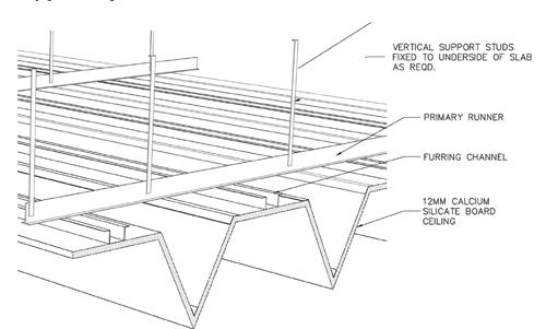
Construction Cafeteria
Documentation &
Site Image
Rendered Visualization
Colored Baffle Ceiling
Isometric Detail
Colored Baffle Ceiling
Reflected Ceiling Plan
Colored Baffle Ceiling
Community within the Ruins
‘From the room to the city’
Graduation Studio|Postgraduate|Individual | Housing
Year: 2021
Location: Macarthur Street, Ultimo, Sydney
Softwares: Rhino, ArchiCAD, Adobe Creative Suite, Physical Modeling
Project Description
The study of the migration pattern of Sydney established the issue of the housing market which is lack of inclusivity in terms of demography, amenities and cost. This drove the research question for this project which investigates the ownership of spaces and its effect on inclusivity.
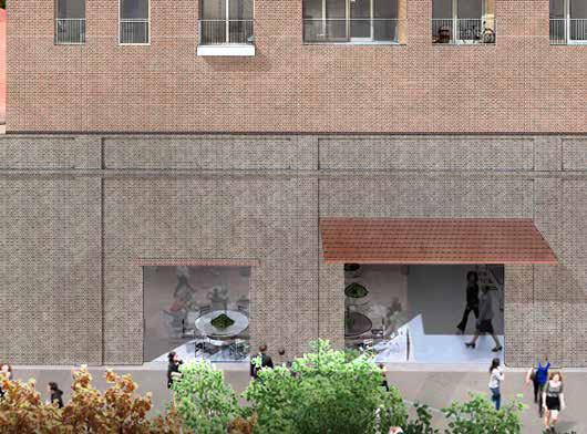
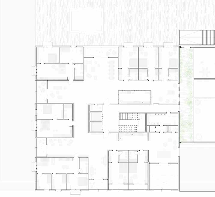
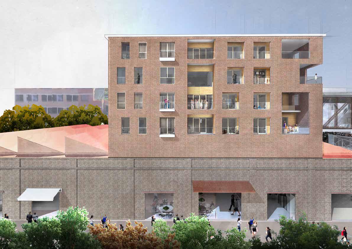
Different levels of sharing form the core experience with the slow progression of spaces as one moves from the public ground plane to their private units. The concept of cluster flats is used to break the confines of a traditional apartment and instead form a multi generational living typology where social interactions are experienced with the insertion of public thresholds through communal spaces in each cluster.
The idea of a ruin is achieved by inserting a new structure within the existing warehouse and exposing the trusses and brick facade; thus creating green pockets that set diverse environments driving interactions at various levels; therefore creating a community within its ruins.
The project aim to investigate the OWNERSHIP of spaces and its effect on INCLUSIVITY in a housing model.
Collective v/s Individual Public v/s Private
Does challenging the ownership of spaces create an inclusive housing model that caters to a diverse socio-economic group?
Size Cost Diversity in People
The Research Question
The Built Form
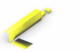

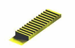
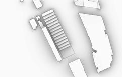
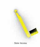


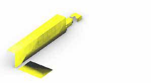
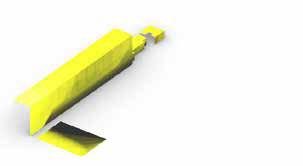


W=103m D= 20m H =30m Overshadowing from High Rise Exisitng Context Constraints Constraints Finalised Rough Mass The built form was refined by looking at the context and existing building. Height of Neighboring Residential 24m
Solar Analysis GSPublisherVersion 0.22.100.100 Define EdgesDemolish Define the Ruin Response to Context & Exsiting Building GSPublisherVersion 0.22.100.100 Define EdgesDemolish & Define Define the Ruin Response to Context & Exsiting Building GSPublisherVersion 0.22.100.100 Define EdgesDemolish Response GSPublisherVersion 0.22.100.100 Define EdgesDemolish & Define Define the Ruin Response to Context & Exsiting Building Response to Context & Exsiting Building The Built Form Define Edges Demolish & Define Define the Ruin Structural Insert Connect Green Interactions
Functional Program
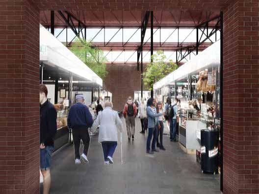
Open Market

OPEN MARKET FOOD HUB BOHASSISTED CAREDIGITAL LIBRARYWOOD WORKSHOPMETAL WORKSHOPCYCLE CENTRE OPEN GYMWORKSPACE SUSHI RESTAURANT BAKERY PAINTER’S GARDEN PAINTER’S GARDEN SUMMER GARDEN RUIN GARDEN GOODS LINE
The Ruin Garden
The
The Ground Plane
Community Level
Functional Program The Community Level
Functional Program
The Community Level
Functional Program
The Community Level


Functional Program
The Cluster Level Functional Program

Unit Level


GAME ZONE KITCHEN KITCHEN LAUNDRY GARBAGE DINE AT THE BIG TABLE EVENING CONVERSATIONS GROUP STUDY OR EAT TOGETHER RUMMAGE THROUGH SHARED STUFF SIT BACK & PLAY WATCH THE HUSTLE & BUSTLE WINE TIME WITH A BOOK LETS READ TWO BEDROOM 2-3 PERSON SMALL FAMILY 60 sq m BEDROOM FAMILY STUDIO 1 PERSON 25 sq m STUDIO 1 PERSON LONE PERSON DR W DW W W W DR DR DW F ONE BEDROOM 2-3 PERSON, COUPLE 50 sq m THREE BEDROOM 3-4 PERSON, LARGE FAMILY 75 sq m
GSPublisherVersion 0.5.100.100 THE SKY TERRACE Key Communal Space Detail Section Cluster Level SKY TERRACE SKY TERRACE BELOW ROOF TERRACE Key Typical Cluster Plan Two Bedroom Unit with Communal Spaces DINE AT THE BIG TABLE EVENING CONVERSATIONS WINE TIME WITH A BOOK Key
The
Communal Space- Detail Section
Front Facade
Green Vein
Gardening as a Communal Activity
Housing : Mixed Use
Academic|Postgraduate|Individual
Year: 2019
Location: ‘Hellhole’ Sandstone Quarry,14 Wattle Street Pyrmont/Ultimo
Site Area: 1.2 Ha
Technical Skills : Archicad, Adobe InDesign, Adobe Photoshop, Adobe Illustrator, Physical Model (Laser Cutting)
Project Description
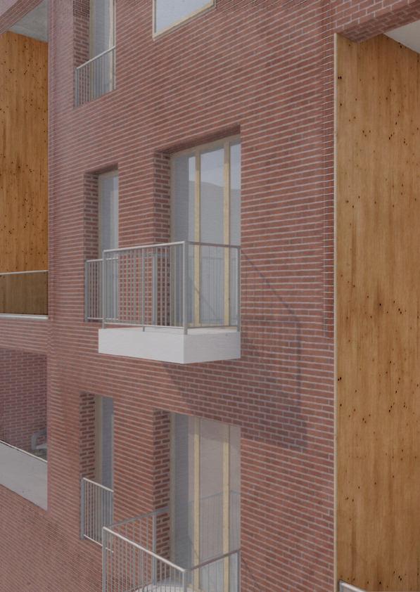
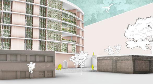
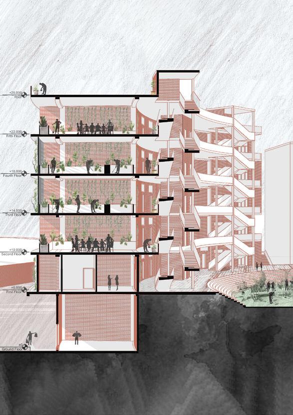
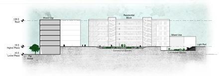
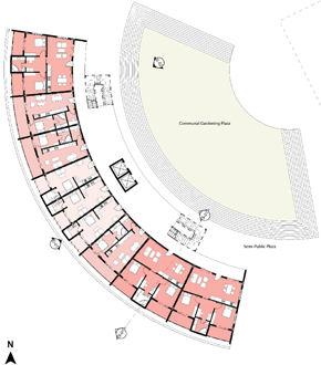
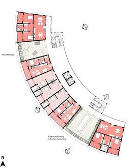
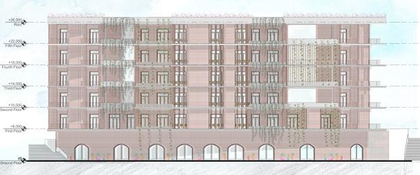
The project addresses the problem of social isolation occurring in apartments of cities by using gardening as a means of interaction and gathering. A Green Vein is introduced vertically along the façade through vines and horizontally through gardening spaces that act as zone for social interaction by intermingling spaces for dining and playing. A mixed-use development is proposed in response to the historical and public nature of the site. A range of apartment types are integrated to allow greater flexibility to choose from, welcoming a range of residents be it a family, student, or young professionals.
Building Section through Communal Spaces
Entrance to Site with Heritage Boundary Wall
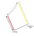

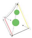


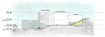



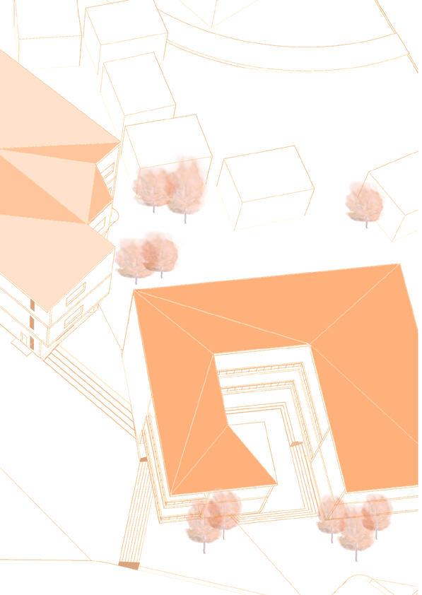
The Site Principle Diagrams Site Plan
Exisitng Movement Form Insertion of Circulation Elements Staircase & Lift
First
Section 01 through Sandstone Wall
Typical
Floor Plan Communal Spaces
Floor, Lvl 6000mm Entrance
Floor
Shape The Curve Green Vein Comunal and circulation spaces intersect vertically ( Facade) and horizonatally (Spatially) as zones of interaction. Proposed Movement DatumCommunal spaces Scale RedefiningCentral mass Moulding Datums as /function Section 02 through Communal Garden The
Elevation 01 with Vines
Plans Redefining
Building Principle Diagrams
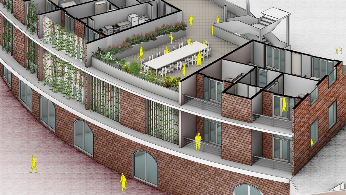
Green Vein Communal Space-Dining Area
Indoor Gardening
with


