THE SHAPE OF BORDEAUX S
t
u
d
i
o
2
0
S
e
m
s
t
e
r
2
2
0
2
0
MASTER OF ARCHITECTURE STUDIO E Design Journal
To n g S u ( 8 4 6 11 2 )
1
Table of Contents 3
Introduction
4 5 6 7-11
1.1 Timber Gridshells Timber gridshell background introduction Individual Form Finding Exercise- Passage design Group Variation - Passage design
12 13 14 15-20
1.2 RC Shells RC shells background introduction Individual Form Finding Exercise- Stage design Group Variation- Stage Design
21 22
1.3 Reinterpretation of a case study and prototyping Smithsonian Institution Courtyard Introduction - Geometry Generation - Grasshopper Definition - Tectonics process and documentation
28
switchwith Savill Garden Gridshell (Glen Howells Architects, 2006) - Variations - Generation - Grasshopper Definition - Final outcome
31 32 33
2.1 The Shape of Wine: design brief & site analysis Site Analysis & Site Selection Concept Development
34
Building Version 1 - improvements (Suites Locations) - Improvements (Gridshell Design
36
Building Version 2
37 38
2.2 Initial Design Response Mid Semester Review - Form Development Diagram & Site plan - Sections & Plans & Isometric Exploede Diagram - Renders
42 43
3 Span and Space Architectural Drawings Development - buildings and gridshell arrangement (3D view) - buildings and gridshell arrangement 1 (plan & section) - buildings and gridshell arrangement 2 (plan & section) - buildings and gridshell arrangement 3 (plan & section) - buildings and gridshell arrangement 4 (plan & section) - buildings and gridshell arrangement 5 (plan & section)
49
Detailing of gridshell - active-bending timber node joint - active-bending timber boundary connection (fixed joint) - active-bending timber boundary connection (pinned joint) - Preformed timber connection
54
Computational Workflow Development - Active Bending Grasshopper Script workflow - Active Bending Grasshopper Script workflow - Computational Workflow - Computational Workflow
59
4 Final Design Proposal
82
Appendix
2
Introduction
How Virtual Becomes Real The computational design is commonly used in nowadays architectural industry, which allows a more convenient and flexible way for the architects. A virous of software enables designers to explore different structures and thoughts using parametric method. This studio is focus on how to design a shell structure, which is the structure with simple materials but with long span without the need of supports in the middle, using grasshopper plug-in such as Kangaroo and Karamba. However more importantly, is to learn how to build the structure which designed using computational tools in the real world.
3
1.1 Active Bending Gridshell Group member: Cecile, Dan, Tong, Callan
4
Timber Gridshell Reverse Hanging Method
Precedent Study - Weald & Downland Open Air Museum
Reverse hanging experiment is an effective method of generating gridshell of shell forms. The method is to invert the hanging chains, or the web network based on the principle of mechanical equilibrium. This method was wildly used by innovative architect when designing and form finding the shell structures such as the roof of Multihalle in Mannheim (Figure 1) and Lath Dome at the German Building Exhibition (Figure 2) by Frei Otto. (Li, Wu, & Borgart, 2015)
The Downland Gridshell Building was a n a c t i ve b e n d i n g t i m b e r g r i d s h e l l structure which is the first timber gridshell constructed in UK using slender oak laths. (Downland gridshell, n.d.) The construction of the gridshell was firstly assemble the gridshell as flat surface at the top part, using the scaffolding to support. Then the edge of the gridshell was lowered gradually to its final position. (Figure 3) The structure is interesting as its edges are straight when the grid is flat (Figure 4), but the final form have curved edge beam to provide better structural stability. (Figure 5)
Figure 1. Final Hanging chain model for Mannheim.
Figure 2. Lath Dome at the German Building Exhibition.
Note. From Case Studies in Structural Engineering, Frei Otto and the development of gridshells, Vol.4, p.41, by I.Liddell, 2015, Copyright 2015 by I.Liddell.
Note. From Form-finding of gridshells generated from hangingchain models by using the Dynamic Relaxation method and the NURBS technique, Proceedings of IASS Annual Symposia, Vol.17, p. 2, by Q. Li, Y.Wu. & A.Borgart, 2015, Copyright 2015 by IASS.
Figure 3. The Gridshell from the North. Note. From Downland gridshell by The Gridshell from the North, n.d., Wealddown. (https://www.wealddown.co.uk/explore/ buildings/further-reading/assembling-grid/?building=301). Copyright by Wealddown.
Gridshell Structure ‘The grid shell is a spatially curved framework of rods and rigid joints. The rod elements form a planar grid with rectangular meshes and constant spacing between the knots [nodes]. The form of a grid shell is determined by inverting the form of a flexible hanging net. To invert the catenary so that it becomes the thrust line of an arch free of moments is an idealisation. Analogously, inverting the form of a hanging net yields the support surface of a grid shell free of moments.’ (Hennicke & Schaur, 1974)
Figure 4. Downland Gridshell lath arrangement.
Figure 5. Downland Gridshell final form.
Note. From Downland gridshell by Downland Gridshell lath arrangement, n.d., Wealddown. (https://www.wealddown. co.uk/explore/buildings/further-reading/assemblinggrid/?building=301). Copyright by Wealddown.
Note. From Downland gridshell by Downland Gridshell final form, n.d., Wealddown. (https://www.wealddown.co.uk/explore/ buildings/further-reading/assembling-grid/?building=301). Copyright by Wealddown.
5
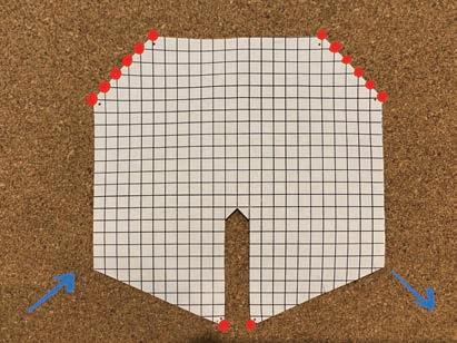
Individual Form Finding Exercise- Passage design with entrance and exit Methodology - Metal Mesh with 5mm grid Structure 1
Structure 2
To test my first idea of active bending gridshell, I was Starting with 1m x 1m square grid to generate the symmetrical form, with same opening shape for entrance and exit. At the same time to create another entrance for passenger. The form was generated by pushing the anchor points inward to see the outcome of the overall form.
My second idea on active bending gridshell is to create different openings by changing the flat shape. Therefore, I rotate the base grid to 45 degree angle and design the openings at diagonal direction. I also want to create different opening for entrance and exit and small opening entrance for passengers as well.
Some further thoughts: A f te r t h e fe e d b a c k from tutors, the gridshell can not have 'flex point' where the bending moment is changed. This will results in the potential structural weak point. 6
Group Variation - Passage design with entrance and exit After the individual variations of the active-bending grid shells, our group decided to keep the feature of rolling passage. To correspond with our design, the site location was selected at the Rolling Hills which situated within the Yarra Valley and the wine region is located just 45km eat of Melbourne's CBD.
Based on our design concept of rolling, several design sketches were generated to test how the opening of the passage grid shell would be to correspond with the topography. Finally, we decided to make the gridshell have serval landing at different height and keep the form as rolling expression. Phsical paper models exploraing the location of landings and openings
7
Group Variation - Grasshopper Definition
1. Set the base grid for active-bending gridshell 2. Set the points on the desire mesh 4. Final result of max displacement.
3. Analysis the structure displacement with two beam sizes.
By using this grasshopper script, we found out that the topography made our exploration really complicated. During this from-found process, a rolling gridshell structure which consist a strip shape to touching the grass land was designed. The feature of this structure was the strip shape, but it also brings lots of problems to the stability of the structure. When looking back to this grasshopper difination, the active bending gridshell can not be simulated using 'points on mesh' component because it did not have the force pushing at connection points. It should be used when generating preformed gridshell.
8
Group Variation - Final Outcome
9
Group Variation - Final Outcome Further thoughts: the elevation shows the overall shape of the gridshell, but there is no edge beams, the connection is not entirely correct because it need to connected with the ground.
10
Group Variation - Final Outcome
11
1.2 RC Shells George, Weishang, Cecile, Tong
12
RC Shells 'Bubble' Shell by Heinz Isler
Precedent Study - Deitingen gas station
The inflated concrete shell was light, can span a long distance without column in between compared with concrete structure in the past. The origin of ‘bubble’ shells was firstly discovered by Heinz Isler with the observation of his pillow shape. (Figure 6) His thought about how to achieve the shell artificially was start from the framework. (Chilton & Isler, 2000) The wooden frame was used to anchor the boundary of the shell which fixed at a timber board, then he drilled a hole at the middle and sealed the connection to allow the air pumped in. (Figure 7) He also marked the mesh grid on the surface so that the inflation effect is easy to observe. However, the structure that he achieved for now have the negative curvature at the corner which will result in the reversal line of thrust. (Chilton & Isler, 2000) What Isler did was to round off the corner which allows the curved boundary at plan view and solved this problem.
Figure 10. Service station in Deitingen ́68, Switzerland by Heinz Isler – Form passive and compressive only structure. Figure 6. Plumped up pillow - the inspiration for Isler's Bubble shells
Figure 7. The original rectangular wooden frame inflated membrance model used by Isler to investigate his bubble shells.
Note. From Heinz Isler: The Engineer's Contribution to Contemporary Architecture.(p. 34), by J. C. Chilton and H. Isler. 2000, Telford. Copyright 2000 by Thomas Telford.
Note. From Heinz Isler: The Engineer's Contribution to Contemporary Architecture.(p. 35), by J. C. Chilton and H. Isler. 2000, Telford. Copyright 2000 by Thomas Telford.
Note. From Structural Implementation of Slender Concrete Shells with Prefabricated Elements, Journal of the International Association for Shell and Spatial Structures, 51-64. by P. Eisenbach and M. Grohmann 2017, Telford. Copyright 2017 by Philipp Eisenbach and Manfred Grohmann.
The cover of service station in Deitingen by Heinz Isler is an concrete shell structure designed by hanging membrane reversed. The structure is pure compressive structure and has a long span covering above the building, which is really effective in relation to the shell thickness. (Eisenbach & Grohmann, 2017) The minimal connection between the shell and the landscape makes the structure ‘floating’ above the ground, and become a part of the nature.
Figure 8. Square demostration inflated membrance model, with a square grid marked on the surface so that the effect of inflation is easily discernible. Note. From Heinz Isler: The Engineer's Contribution to Contemporary Architecture.(p. 35), by J. C. Chilton and H. Isler. 2000, Telford. Copyright 2000 by Thomas Telford.
Figure 9. Acquiring the form by inflation of the membrance just as the plaster mixture is setting. Note. From Heinz Isler: The Engineer's Contribution to Contemporary Architecture.(p. 36), by J. C. Chilton and H. Isler. 2000, Telford. Copyright 2000 by Thomas Telford.
13
Individual Form Finding Exercise- Stage design During this week, we were asked to produce a 2D catenaries form first and then transfer this form into the Karamba to analysis the structure.
The test of how different anchor points and strength will influence the form was produced.
Then the 2d catenaries was transformed into 3 dimensions to generate mainly symmitrical forms.
Strength Ourcom Testing
2000
1000
500
300
Final Form Outcome STRETCH 9.55%, (15,0,0)
3 END POINTS
4 END POINTS
4 END POINTS 6 END POINTS
4 END POINTS
Concept Form Finding
STRETCH 6.04%, (10,0,0)
Curve boundary
Delete Catenaries M a k e s t a g e at the boundary boundary stright
Final form
STRETCH 14.03%, (5,0,0)
The form gives the sense of stage and also have unique tile which cover across the audience as well. Feedback: the segments needs to be connected which can be achieved simply by seprate the lines when drawing in the top view. 14
Group Variation - Final Outcome
15
Group Variation - Structaure analysis variations
16
Group Variation - Structaure analysis variations
The variations were made mainly according to the individual design, which testing the angle formed by catenaries. Then we found that the long space tile which only got one support point at the end will increase the displacement of the whole structure. Therefore, we did change the design of two supporting points at the end to stabilize the structure and decrease the displacement.
17
Group Variation - Final Ourcome Feedback: Need to keep the drawings consistancy, the rib shows at the plan need to shows at the section as well.
18
Group Variation - Grasshopper Definition
2. Patch the surface in rhino and then inport to Karamba. 4. Max displacement is 0.67 cm.
1. Using Kangaroo to ge n e rate t h e fo r m then bake. 3. List the support points for the mesh.
Further Thoughts: The method that generate the form firstly in kangaroo then put it in Karamba will not allowing the further optimisations or changes of the design.
19
Group Variation - Final Ourcome Further Thoughts: The connection point between the 'tile' and the cover forms an structural weak area, needs to be fixed at the future design.
20
1.3 Reinterpretation of a case study and prototyping Smithsonian Institution Courtyard (Foster+Partners, 2007)
Group member: Tan, Tong
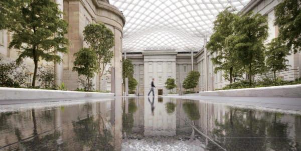
Figure 11. Smithsonian Institution Courtyard Note. From 2007-Washington DC, USA Smithsonian Institution Courtyard by Forster and Partners, 2007, Forster and Partners (https://www.fosterandpartners.com/projects/smithsonian-institution-courtyard/). Copyright 2020 Foster + Partners.
21
Smithsonian Institution Courtyard (Foster+Partners, 2007) Introduction
Figure 13. Smithsonian Institution Courtyard sketch Note. From 2007-Washington DC, USA Smithsonian Institution Courtyard by Forster and Partners, 2007, Forster and Partners (https://www.fosterandpartners. com/projects/smithsonian-institution-courtyard/). Copyright 2020 Foster + Partners.
The sketch produced by Norman foster illustrates the diagonal grid surface with three domes flowing along the forms roof of the existing building. (Figure 13) The key design thought is that the shape of the sound.
Figure 12. Smithsonian Institution Courtyard Note. From 2007-Washington DC, USA Smithsonian Institution Courtyard by Forster and Partners, 2007, Forster and Partners (https://www. fosterandpartners.com/projects/smithsonian-institution-courtyard/). Copyright 2020 Foster + Partners.
The roof is also design due to the space was exposed to the environments which will be influenced by the weather before. There are also lots of constraints and challenges when designing the structure like the edge beam location, dome height, drainage, prefabrication & assemble on site.
The Smithsonian Institution consisted with the former United States Patent Building, and now has transferred to use as the National Portrait Gallery and the Smithsonian American Art Museum by President Eisenhower. (Foster+Partners, 2007) As its purpose is the Gallery, the courtyard connected with different exhibitions and was asked to be designed to host a range of social events. The fully glazed roof allows sunlights went through and consisted with three interconnected vaults with curved valleys. The double-glazing panel is chosen consisted with acoustic material cladding to form the gridshell, and supported by eight columns at the lowest point. (Foster+Partners, 2007) Figure 14. Smithsonian Institution Courtyard roof cladding Note. From 2007-Washington DC, USA Smithsonian Institution Courtyard by Forster and Partners, 2007, Forster and Partners (https://www.fosterandpartners. com/projects/smithsonian-institution-courtyard/). Copyright 2020 Foster + Partners.
22
Smithsonian Institution Courtyard (Foster+Partners, 2007) Geometry Generation After having a basic sense of the structure, we did two attampts to achieve the final form. The first one is to drag the points in rhino to form the surface, another one is using Kangaroo to set out the diagrid and using lines to restrain the form.
Method 1 : Rhino
1. Analysis proportion, and create flat surface
2. Pull points and Rebuild surface : U:11, V:7
3. Adjust surface
4. Create diagonal grid with Grasshopper
Method 2: Kangaroo
1. Analyze support proportions, and create flat surface
2. Set the diagonal grid 2m x 2m
3. Set the supporting columns and load facing up
4. Restrain the boundary points and m ake it only moves vertically
5. Set boundary points fixed
6. Allocating 6 lines to restrain the surface
23
Smithsonian Institution Courtyard (Foster+Partners, 2007) Grasshopper Definition
Method 1 : Rhino Max displacement 4.2 cm
Create the surface and attach with diagonal mesh 2m x 2m
The method one attempted have a quite simple workflow, but if the structure is not satisfied, the surface need to be redo in rhino and reference in grasshopper again, which provides less control on the overall form.
Rhino surface
Karamba Structural AnalysisModel
24
Smithsonian Institution Courtyard (Foster+Partners, 2007) Grasshopper Definition Max displacement 3.73cm
Method 2. Grasshopper
1. Diagonal Mesh
2. Support points + restrain boundary
4. Set 6 Restrain lines
3. Set Fix boundary points 5. Make the surface more soft and smooth
In this case, grasshopper gives more control on the form and can be easily changed of the karamba analysis result is not satisfied. But in the end, the kangaroo can no generated the same form with Smithsonian Institution Courtyard, we agreed on that the form is not generated by grasshopper. However, the method is worth to try if we are trying to create the form.
Rhino surface
Karamba Structural AnalysisModel
25
Smithsonian Institution Courtyard (Foster+Partners, 2007) Tectonics Studies
1. Since the enclouse has a log span, modeulare assemblt is needed
4. After Frabrication the grids are spot welded, with the support of a scaffording
2. the grid componenet a broken down segment, prefabricated before assemble
5 . Frame are sand blast, coat, and cladded by acoustic panels
3. Coumn top are casted, and connected to grid element
6. Finally Glass Panel is installed
26
Smithsonian Institution Courtyard (Foster+Partners, 2007) Tectonics Documentation
Detailed connection betwwen beams and the box girder
Thicker beam and column connection 27
Smithsonian Institution Courtyard (Foster+Partners, 2007) & Savill Garden Gridshell (Glen Howells Architects, 2006) Variations Variation 1
1 . U s i n g s a m e m e t h o d fo r g e o m e t r y generation, surfaces are controlled by points
2. By swapping site, the context change, from 3. Frames and Panels are added with GH + 4. Transparency are created from all sides to a tall enclouse to a long narrow strip that flow Lunch Box Panel and frame component then emphasize to the lansacape. extruded the frames along the landscape
Variation 2
1. According to our case study design brief, the shape of the roof designed to be symmetrical
2. Set out the grid of 2m x 2m and trimmed according to the shape boundary
3. Using "points on mesh" to stimulate the shape of our case study
4. Convert the grid shell into Karamba to analysis the structure
28
Smithsonian Institution Courtyard (Foster+Partners, 2007) & Savill Garden Gridshell (Glen Howells Architects, 2006) Grasshopper Definition
1. Set out the grid of 2m x 2m and trimmed according to the shape boundary
2. Using "points on mesh" to stimulate the shape of our case study 3. Convert the grid shell into
Karamba to analysis the structure
29
Smithsonian Institution Courtyard (Foster+Partners, 2007) & Savill Garden Gridshell (Glen Howells Architects, 2006) Variation final outcome
Aerial View
Hero Shot
Some further thoughts:
Section View
Plan view
The support needs to be offset a little bit which will enhance the structural stability. The edge of the structure seems curved too much, so the vaults can be smaller.
30
2.1 The Shape of Wine design brief & site analysis
Overal building arrangement sketch
31
SITE ANALISIS
SITE SELECTION
Our site is located at the Yarra Valley which close to the Yarra Glen suburb and connected with Old Healesville road. It consisted with two lakes and also the Denton House with large area of vineyard. According to the brief, our client Denton Wine are planning to have a winery to host a variety of activities, from wine production to wine tasting, accommodation, etc.
SITE
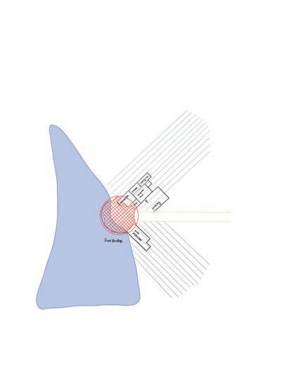
According to the site analysis, we picked the lowest point of the whole site which will not block the rainwater flow but also having more nature atmosphere close to the lake. The site also have the good accessibility which closed to the road. TOPOGRAPHY SITE PLAN
RAINWATER FLOW SITE PLAN
SITE SELECTION MAP
SITE
YARRA GLEN
SITE LOCALITY PLAN 3 32
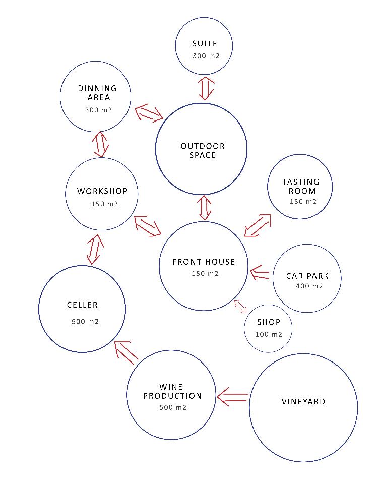
CONCEPT BRIEF DEVELOPMENT PRECEDENT STUDY: Pt. Leo Estate According to the client brief and our discussion we mainly divided the functions below: - VINEYARD - VINE PRODUCTION (500 m2) harvested, sorting, destem, pressing, fermentation, filtration, bottling, aging - VINE CELLAR (900 m2) - WINE TASTING ROOM (80 -100 m2) - FRONT HOUSE(150 m2) - RESTAURANT (300 m2) - OUTDOOR (WEDDING, CONCERT, WINE TOUR Harvest, Grape Stomping, TEAM BUILDING ) - SUITE (5: 60 m2 each) - SHOP (100 m2) - PARKING (400 m2)
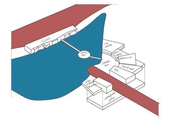
The initial form of the winery was developed from the function bubble diagram which has couryard at the middle and the functions were allocated arround. The gridshell was designed to cover the outdoor area. The main entrance of the site is located at the right side which closed to the main road. As shown in the section sketch, the entrance is at the level 1 and the cellar is located at the underground level.
Figure 15. Pt. Leo Estate Detailed Plan
Figure 16. Pt. Leo Estate Detailed Plan
Note. From Pt. Leo Estate / Jolson Architecture and Interiors by Jolson Architecture and Interiors, 2018, Archdaily (https://www.archdaily.com/897555/ pt-leo-estate-jolson-architecture-and-interiors). Copyright 2018 by Jolson Architecture and Interiors.
Note. From Pt. Leo Estate / Jolson Architecture and Interiors by Lucas Allen, 2018, Archdaily (https:// www.archdaily.com/897555/pt-leo-estate-jolsonarchitecture-and-interiors). Copyright 2018 by Lucas Allen.
- Curvaceous form - The programs are happening around the entrance courtyard. The lowest point of whole architecture is at the courtyard - Have a seprated staff entrance - Access to sculpture exhibition - Door to underground cellar - Commercial store, outdoor dining
INITIAL SITE PLAN SKETCH
INITIAL HERO SHOT SKETCH
INITIAL SECTION SKETCH
4 33
DESIGN DEVELOPMENT
IMPROVEMENT - SUITES LOCATIONS Several suites locations was explorated to test whether it is suitable for the whole winery. The advantages and disadvantages were listed for each option, then we decided to located the suites above the lake which will keep the consistency but also having the privacy looking the opposite direction of the winery.
VERSION 1
DESIGN VERSION 1 PERSPECTIVE
DESIGN VERSION 1 GROUDN FLOOR PLAN
- Lack of privacy - View blocked by winery - Form : not consistent with winery design
- Noise (close to wine factory ) - Form : not consistent with winery design
- Noise (close to commercial area ) - Area of suites is relatively smaller compare to other scheme
- View not blocked - Privacy is preserved - Form - consistent - Good accessibility - Special living experience
- Form : not consistent with winery design - Not accessible from winery
Final suites location
DESIGN VERSION 1 LEVEL 1 PLAN
DESIGN VERSION 1 UNGROUND FLOOR PLAN
FEEDBACK - Introduce the grid shell into the design - Maybe better if we can keep the whole architecture consistent, for example to keep the suites into the circular form as well - Get rid of the bridge as it is not consistent with the whole architecture - Could be further developed by considering the landscape into the design - The suites were looking to the winery which the privacy cannot be guaranteed, therfore looking for another location such as the other side of the lake
5 34
DESIGN DEVELOPMENT IMPROVEMENT - GRIDSHELL DESIGN OPTION 1 GRIDSHELL FOR WINERY AND SUITES
OPTION 4 GRID SHELL FOR WINERY AND TENSILE SHELL FOR SUITES
In this design, the shelled is coving most of the open space and also the suites. the opening of winery gridshell give the area to locate the stage.
The form is inspired of the precedent Morongo Casino & Resort. The grid shell start from the middle of the outdoor area and ends at the roof edges. The shells are also design above the suites to keep the consistency of the whole structure.
OPTION 5 GRID SHELL FOR WINERY AND TENSILE SHELL FOR SUITES
OPTION 2 GRIDSHELL FOR WINERY AND SUITES
The form is inspired of the precedent Morongo Casino & Resort and having the connected part which close to the ground connection.
OPTION 3 TENSILE SHELL FOR WINERY AND SUITES
The form is inspired from the study of catenary in week 2. The anchor points are located at each rood edge of buildings which shows the contrast with the regular buildings.
In this case the grid shell for the suites are covering the building separately.
Figure 17. Morongo Casino Gridshell
Figure 18. Pt. Cabot Circus Gridshell
Note. From Morongo Casino & Resort Cabazon, California by Mike Hughes Architects, n.d., Mike Hughes Architects(https://mikehughesarchitects. com/morongo-casino-resort/). Copyright by MIKE HUGHES ARCHITECTS.
Note. From Cabot Circus by Jon Cook, 2015, Timeout (https://www.timeout.com/bristol/attractions/cabotcircus). Copyright 2015 by Jon Cook.
Figure 19. Didier Boy de la Tour. Swatch and Omega Campus. Note. From Swatch and Omega Campus / Shigeru Ban Architects by Didier Boy de la Tour, 2019, Archdaily (https:// www.archdaily.com/926166/swatchand-omega-campus-shigeru-banarchitects?ad_medium=gallery). Copyright 2015 by Didier Boy de la Tour.
The precedent study of grid shell was mainly looked at the shells touches the buildings. After we received the feedbacks from the grid shell design, we mainly focus on the Cabot Circus which having the free form shell floating above different buildings and forms the contrast. 6 35
DESIGN DEVELOPMENT VERSION 2
DESIGN VERSION 2 GROUND FLOOR PLAN
DESIGN VERSION 2 LEVEL 1 PLAN
DESIGN VERSION 2 PERSPECTIVE
In this version, the grid shell is separated into two parts which covering the outdoor space and suites as well. The main sense it wants create was to generate a free form structure floating above the buildings to give the contrast with the architecture. Then the basic building plan layout was designed into details to show how the functions were worked.
FEEDBACK The feedbacks for this version was mainly to design the grid shell further as it seems different and wired in some angles. The grid shell need to be simple and strong itself stand with clear form and structure resistance. The heroshot need to be labeled the functions as well to show how the architecture works clearly.
7 36
2.2 Initial Design Response - Mid Semester Review 37
MID SEMESTER REVIEW
1. Basic form with courtyard
2. Select the potential site location close to the lake
3. Split the builing form according to the road and the lake to have commercial area, wine production and suites
FORM DEVELOPMENT DIAGRAM: The overall form was generated from the initial idea of allocating all the functions around the outdoor area, then was interrupted by the site features and the road to separate the commercial, suites and wine production areas. Then the grid shell was introduced into the site to cover the courtyard. The gridshell has large span at ground level which allow different activities happening such as concert or wedding.
7. Finalized the grishell design which span between different buildings to create the contrast between the free form gridshell and building blocks
6. Introduce the shell to cover the ourdoor space and provide shading for outdoor activities
4. Refine the building forms to achieve the consistency
5. Divide massings into different functions and having pitched roofs to corrspond with the topography
8 38
MID SEMESTER REVIEW The main entrance is located at level 1 which designed correspond with the landscape, which closed to the carpark space. Then the private tasting room was along located with a semi private outdoor chill out space.
Another entrance for the visitors was designed at the ground floor facing to the commercial shop. The area nearby is the wine workshop area which allows people looking down to barrels. Then the dining area and kitchen was aligned to provide resting space or activities for visitors.
The exploded diagram shows the structure and the columns at each level. The wine production hall and the reception hall are designed to be double height which allows more sunlights. The roof of each function are designed to be pitched which aimed to correspond with the landscape and the lake.
The underground level consisted with the barrels and also storage shelfs used by the winery.
The section shows connection between the grid shell, suites and the buildings. The underground barrels are allow to look at from ground floor. 9 39
MID SEMESTER REVIEW
GRIDSHELL HERO SHOT Feedbacks: - connection between gridshell and ground / buildings need to resolve; what's the design intent? - site (high point vs low point); consider how water interacts with the building - suites on water - elevate more the visual - can use the grid shell to design space more deliberately - be mindful of orientation for buildings for volumes - tie the programs together with form-generation
HERO SHOT FROM LAKESIDE
10 40
MID SEMESTER REVIEW IMPROVEMENT GRIDSHELL VERSION 1
Figure 20. Trinity Leeds Gridshell Roof Structures.
Figure 21. Trinity Leeds Gridshell Roof Structures.
Note. From Trinity Leeds Gridshell Roof Structures by Landsec, 2013, Structural Awards 2020 (https:// www.istructe.org /structuralawards/winners/ retail-structures/2013/trinity-leeds-gridshell-roofstructures). Copyright 2013 by Landsec.
Note. From Trinity Leeds Gridshell Roof Structures by Landsec, 2013, Structural Awards 2020 (https:// www.istructe.org /structuralawards/winners/ retail-structures/2013/trinity-leeds-gridshell-roofstructures). Copyright 2013 by Landsec.
GRIDSHELL VERSION 2
According to the feedback from the mid term review, the design intent of the gridshell is not strong enough. Therefore, we discussed about the atmosphere that our gridshell want to generate. The gridshell we want to create is a coverage of the ou door space but also give the sense of extending indoor area to the outer space which forms a semi private courtyard and allows people to relax. As a result, we changed the gridshell to make it entirely closed with the buildings but having large span close to the lake. Then the idea is using the cladding to cover the grids and gradually become transparent from buildings to the lake.
After we finished the version 1, we found out that the form is not persuasive enough. The shape of the gridshell seems seprated with the whole structure. Therefore, we tried to extend the boundary of the gridshell to cover the building roofs and also the suites. This makes the transformation from buildings to the courtyard more obvious. The cladding will also change from solid to transparent from the boundary to the middle. The gridshell brings all the buildings together and keep the consistency of the whole structure.
11 41
3 Span and Space - Architectural Drawings Development 42
DESIGN EXPLORATION - buildings and gridshell arrangement (3D view) PRECEDENT STUDY
OPTION 1
PRECEDENT STUDY
Deubau Gridshell
circular gridshell and buidlings alined with wineyard
Chastone Shopping Centre gridshell with connection at Roof Gridshell the centre and buidlings alined with wineyard
The gridshell designed by FREI OTTO HAD in 1962 which have the span of 15m x 15m at the German Building Exhibition. The access into the gridshell was designed by cutting the opening into the grid and creating the reinforced edge beam. The option 1 shows a simplified plan form and also the gridshell. The flat configuration of the grid is square, which the circular form coving all the footbridge. The buildings are designed aligned with the vineyard which aiming to not interrupt the existing environments.
The new Chadstone shopping centre roof was designed by Callison RTKL and Atelier One, which aiming to covering the 7,000sqm of the shopping centre. The gridshell was designed in curve shape at the connection edges, which forms a really nice view at the perspective as shown in Figure 3. The options 2 was inspired by this design and we trying to create the different connection area at the middle of the circle. The area created at the middle which will formed other functions and contribute to the wine yard.
OPTION 2
PRECEDENT STUDY
OPTION 3
King's Cross Station in London
Semicircle gridshell with connection at the centre and buidlings with previous form
The gridshell was design by John McAslan and Partners which aiming to cover the extended area of the King’s Cross station. It have the close connection with the building and creates the beautiful shadings generated by the cladding. The options 3 was inspired by the form of this gridshell of its connection with the building and also the ground.
Figure 24. King’s Cross Station Figure 22. Lath Dome at the German Building Exhibition. Note. From Form-finding of gridshells generated from hanging-chain models by using the Dynamic Relaxation method and the NURBS technique, Proceedings of IASS Annual Symposia, Vol.17, p. 2, by Q. Li, Y.Wu. & A.Borgart, 2015, Copyright 2015 by IASS.
Figure 23. Gridshell roof installed at Chadstone shopping centre Note. From WATCH: First-of-its-kind gridshell roof installed at Chadstone shopping centre by Nathan Johnson, 2016, Architectureanddesign (https:// www.architectureanddesign.com.au/ news/watch-first-of-its-kind-gridshellroof-installed). Copyright 2016 by Nathan Johnson.
Note. From King’s Cross Station / John McAslan + Partners by Hufton + Crow, 2012, Archdaily (https://www. archdaily.com/219082/kings-crossstation-john-mcaslan-partners). Copyright 2012 by Hufton + Crow.
43
DESIGN EXPLORATION - buildings and gridshell arrangement (plan & section) PRECEDENT STUDY - Mont-Ras Winery in Girona
EXPLORATION 1
Figure 24. Winery in Mont-Ras Facade. Note. From Winery in Mont-Ras / Jorge Vidal + Víctor Rahola by José Hevia, n.d., Archdaily (––-). Copyright by José Hevia.
Figure 25. Winery in Mont-Ras Tasting Room. Note. From Winery in Mont-Ras / Jorge Vidal + Víctor Rahola by José Hevia, n.d., Archdaily (https://www.archdaily.com/805958/winery-inmont-ras-jorge-vidal-plus-victor-rahola). Copyright by José Hevia.
Figure 26. Winery in Mont-Ras Fermentation hall. Note. From Winery in Mont-Ras / Jorge Vidal + Víctor Rahola by José Hevia, n.d., Archdaily (https://www.archdaily.com/805958/winery-inmont-ras-jorge-vidal-plus-victor-rahola). Copyright by José Hevia.
The precedent we studied this case is the Mont-Ras Winery in Girona designed by Spanish architect Jorge Vidal and Victor Rahola. The building designed with flat roof and the tunnel like space inside the building which connected with the owner’s house. The feature that attract us was the atmosphere of the tasting room as shown in Figure 8, with a large window leading the view to the vineyard. It also connected with several tunnels and each of them leading to a different function of the winery. As inspired of the Catalan Vineyard, we arranged the building plan as liner which aligned with the vineyard. The functions of the winery were mainly divided into two parts: commercial and suites. The commercial part of the winery was design to have a large atrium in the middle, with wine production function happening at the ground floor. Due to the sloping landscape of the site, the main entrance was designed at the first floor, and the restaurant and tasting room was closed to the main entrance. The tasting room was inspired by the precedent Mont-Ras Winery in Girona, with the extended view to the vineyard which creates the unique experience when tasting the wine.
44
DESIGN EXPLORATION - buildings and gridshell arrangement (plan & section) PRECEDENT STUDY - Antinori Winery
EXPLORATION 2
Figure 27. Antinori Winery Entrance. Note. From Antinori Winery by Archea Associati by Pietro Savorelli, 2013, Dezeen (https://www.dezeen.com/2013/05/04/antinori-winery-byarchea-associati/). Copyright by Pietro Savorelli.
Figure 28. Antinori Winery Tasting room. Note. From Antinori Winery by Archea Associati by Pietro Savorelli, 2013, Dezeen (https://www.dezeen.com/2013/05/04/antinori-winery-byarchea-associati/). Copyright by Pietro Savorelli.
The precedent study based on the Antinori Winery designed by Archea Associati in 2012. The architecture levels are not strictly following the traditional floor level, but extended with the natural landscape, and at the same time exploring different internal space generated natural element. For example, according to the figure 11, the tasting room was extruded into the cellar area, and the sharp edges was contrasted with the cave like cellar area. It provides the interactions between the cellar and the people tasting wine in the tasting space. Moreover, the spaces are connected using a huge stair and keep the areas as a whole. When we are exploring the plan and sections, we were trying to arrange the functions freely with the building volume. It can be shown in the sections that each function is not aligned into one single level, instead the functions was designed according a big stair from bottom to the top. Then the functions are all connected with the stair which creates a journal for the users from wine production to suites.
Figure 29. Antinori Winery Facade. Note. From Antinori Winery by Archea Associati by Pietro Savorelli, 2013, Dezeen (https://www.dezeen.com/2013/05/04/antinori-winery-byarchea-associati/). Copyright by Pietro Savorelli.
45
DESIGN EXPLORATION - buildings and gridshell arrangement (plan & section) PRECEDENT STUDY - Medhurst Cellar Door and Winery
EXPLORATION 3
Figure 30. Medhurst Cellar Door and Winery External. Note. From Medhurst Cellar Door and Winery / Folk Architects by Peter Bennetts, 2019, Archdaily (https://www.archdaily.com/929952/ medhurst-cellar-door-and-winery-folk-architects). Copyright by Peter Bennetts.
Figure 31. Medhurst Cellar Door and Winery Fermentation Hall. Note. From Medhurst Cellar Door and Winery / Folk Architects by Peter Bennetts, 2019, Archdaily (https://www.archdaily.com/929952/ medhurst-cellar-door-and-winery-folk-architects). Copyright by Peter Bennetts.
The Medhurst Cellar Door and Winery project by Folk Architect is a great precedent on the simplification of form and function. The project only involves the wine production, cellar and the office, but it still creates a great consistency on the function arrangements and also the interactions between the functions. It has the cellar space and fermentation hall located the ground floor and the main entrance at the first floor. The overall form and functions are simple and clear but involves a good and reasonable circulation inside the building. The architecture also has an offset entrance for visitors’ access to the building easily. The exploration 3 of plans and sections was put the user’s circulation at the priority, which involves the offset of the entrance at both ground floor and section floor. At the first floor, the tasting room and the restaurant are designed with a look out area which allows the visitors to have the view of fermentation hall and the cellar. The suites are designed with the intersections of internal courtyard. The layout is simple and easy to access.
Figure 32. Medhurst Cellar Door and Winery Architectural Plan. Note. From Medhurst Cellar Door and Winery / Folk Architects by Folk Architect, 2019, Archdaily (https://www.archdaily.com/929952/ medhurst-cellar-door-and-winery-folk-architects). Copyright by Folk Architect.
46
DESIGN EXPLORATION - buildings and gridshell arrangement (plan & section) PRECEDENT STUDY - Lahofer Winery
EXPLORATION 4
Figure 33. Lahofer Winery External View. Note. From Lahofer Winery / CHYBIK + KRISTOF by Alex shoots buildings, 2019, Archdaily (https://www.archdaily.com/945154/lahofer-winerychybik-plus-kristof). Copyright by Alex shoots buildings.
Figure 34. Lahofer Winery External View. Note. From Lahofer Winery / CHYBIK + KRISTOF by Alex shoots buildings, 2019, Archdaily (https://www.archdaily.com/945154/lahofer-winerychybik-plus-kristof). Copyright by Alex shoots buildings.
According to the precedent study, it connects the landscape and the building as a whole by introducing a big ramp into the architecture and also maximizing the views at the same time. The opening at the main entrance and also at the side and back facing to the vineyard connect the surrounding and the building together. The wine production related functions are designed away from the commercial part which allows the privacy of the winery. In this case, the exploration divided the functions into two main parts: wine production and commercial part. To be simplified the functions of our winery, the suites are canceled due to the service and maintenance issues. The commercial part will facing to the public which consist with restaurant and also the open exhibition of wine-related knowledge. According to the section, the view of the restaurant and tasting room was introduced by apply the sloping roof.
Figure 35. Lahofer Winery Architectural Plan. Note. From Lahofer Winery / CHYBIK + KRISTOF by CHYBIK + KRISTOF, 2019, Archdaily (https://www.archdaily.com/945154/lahofer-winerychybik-plus-kristof). Copyright by CHYBIK + KRISTOF.
47
DESIGN EXPLORATION - buildings and gridshell arrangement (plan & section) PRECEDENT STUDY - Austria's Clemens Strobl winery
EXPLORATION 5
Figure 36. Austria's Clemens Strobl winery Tasting Room. Note. From Grey shades permeate interiors of Austria's Clemens Strobl winery by Natasha Levy, 2020, Dezeen (https://www.dezeen. com/2020/09/22/clemens-strobl-winery-interiors-austria/). Copyright by Natasha Levy.
Figure 37. Austria's Clemens Strobl winery restaurant. Note. From Grey shades permeate interiors of Austria's Clemens Strobl winery by Natasha Levy, 2020, Dezeen (https://www.dezeen. com/2020/09/22/clemens-strobl-winery-interiors-austria/). Copyright by Natasha Levy.
Figure 38. Austria's Clemens Strobl winery Architectural Plan.
The precedent for the exploration 5 was the Austria’s Clemens Strobl Winery which designed by Destilat. The winery consists of wine production, restaurant, tasting and cellar area. The wine production and the commercial area was connected using the tasting room which shown as Figure 19. This precedent combined all elements into one linear building but without obvious level divisions. The double height of the space maximum the lights went into the building. As inspired by the precedent, our winery divided the functions into restaurant and winery, as the restaurant have the most separated function with the winery, and also it will be interesting to put the wine production and the tasting room to create the atmosphere shown in the precedent. The gridshell covers the foot bridge which have 4 connection areas to the building and the ground, aiming to leave the views towards the Denton House and the view of the lake. The landing of the gridshell attached with the building gives the opportunities for visitors to interact with the gridshell. The atmosphere we want to create is the rural buildings using concrete, stone or other local materials with a timber gridshell floating above the lake and only leave the views that we want visitors to look at deliberately.
Note. From Grey shades permeate interiors of Austria's Clemens Strobl winery by Destilat, 2020, Dezeen (https://www.dezeen.com/2020/09/22/ clemens-strobl-winery-interiors-austria/). Copyright by Destilat.
48
3 Span and Space - Detailing of the Gridshell Design The method we used to design our form-resistant structure is form-finding process. We tried to generate our gridshell using active bending and preformed timber gridshell stimulation through Kangaroo. The connection method we are researching are the timber laths connection and also the connection between the shell and the buildings/ground.
Figure 39. Trio Gridshell Conenctions. Note. From Gridshell’s Parametrically-Designed Canopy Shades Masseria Ospitale Restaurant in Lecce, Italy by Inhabitat, 2013, Inhabitat (https:// inhabitat.com/gridshell-creates-a-parametrically-designed-shadestructure-for-masseria-ospitale-restaurant-in-lecce-italy/gridshellitaly-6/). Copyright by Inhabitat.
49
DETAILING EXPLORATION - active-bending timber node joint
Figure 40. Timber gridshells node details. Note. From TECTONIC DESIGN OF ELASTIC TIMBER GRIDSHELLS, p. 9, by Jorge G. F. and Poul H. K. and Jorge M. B., 2016, Copyright by Jorge Fernandes.
Figure 41. (a)Typical node as realised in the gridshell (b)Typical node joint of the Multihalle, Mannheim Note. From TIMBER GRIDSHELLS A R C H I T E C T U R E , S T R U C T U R E AND CRAFT, by J. Chilton and G. Tang, 2017, Routledge. Copyright 2017 by John Chilton and Gabriel Tang.
SECTION OF ACTIVE BENDING TIMBER NODE JOINT
DIAGRAM OF CLAMPING JOINT DETAIL
Figure 42. Typical node joint of the Jerwood Gridshell.
Figure 43. Clamping detail as built.
Note. From TIMBER GRIDSHELLS A R C H I T E C T U R E , S T R U C T U R E AND CRAFT, by J. Chilton and G. Tang, 2017, Routledge. Copyright 2017 by John Chilton and Gabriel Tang.
Note. From TIMBER GRIDSHELLS A R C H I T E C T U R E , S T R U C T U R E AND CRAFT, by J. Chilton and G. Tang, 2017, Routledge. Copyright 2017 by John Chilton and Gabriel Tang.
After researched the node connection of the timber gridshell, the most commonly used method is using bolts and clumping joint. However, due to our gridshell was spaned around 50m which is a relatively large gridshell, the clumping joint seems too expansive compared with the bolts joint. We modeled and draw the section and 3D model of the two methods as explorations, and we decided on to use the bolted joint for construction.
ISOMETRIC DIAGRAM OF CLAMPING JOINT CONNECTION
50
DETAILING EXPLORATION - active-bending timber boundary connection (fixed joint)
FIXED JOINT AT THE BOUNDARY CONNECTION
Figure 44. Detail of Boundary connection.
Figure 45. Multihalle Gridshell Boundary connection.
Note. From Case Studies in Structural Engineering, Frei Otto and the development of gridshells, Vol.4, p.41, by I.Liddell, 2015, Copyright 2015 by I.Liddell.
Note. From MULTIHALLE MANNHEIM by Wooddays, n.d., Wooddays (https://www.wooddays.eu/en/ architecture/best-practice-architecture/detail/multihalle-mannheim/index.html). Copyright by proHolz Austria.
FIXED JOINT AT THE BOUNDARY CONNECTION ISOMETRIC DIAGRAM
According to our research, The connection between the gridshell and the building/ground mainly using two method: pinned and fixed joint. It depends on how we gonna construct the gridshell on site. The fixed joint can be shown at the section at the upper right corner. This method is what we used for the ground connection, which consist the edge beam and the steel plate to connect the gridsehll and the concrete column. This method was used when the gridshell was fixed at the beginning and banded at the other end.
FIXED JOINT AT THE BOUNDARY CONNECTION ISOMETRIC DIAGRAM
51
DETAILING EXPLORATION - active-bending timber boundary connection (pinned joint)
Figure 46. AIRSHELL - Bending timber with air. Note. From AIRSHELL - Bending timber with air by Melbourne School of Deisgn, 2017, Youtube (https://www. youtube.com/watch?v=6flPMmNxUVA&ab_channel=%E9%82%A3%E4%BA%9B%E5%A5%BD%E5%90%AC%E7% 9A%84%E6%AD%8C). Copyright by Melbourne of Design.
PINNED JOINT AT THE BOUNDARY CONNECTION ISOMETRIC DIAGRAM
Figure 47. GILMAN HALL Section.
Figure 48. GILMAN HALL.
Note. From GILMAN HALL by Carolynouwehand, 2010, Carolynouwehand (https://www.carolynouwehand.co.uk/gilmanhall). Copyright by Carolynouwehand.
Note. From GILMAN HALL by Carolynouwehand, 2010, Carolynouwehand (https://www.carolynouwehand.co.uk/gilmanhall). Copyright by Carolynouwehand.
PINNED JOINT AT THE BOUNDARY CONNECTION ISOMETRIC DIAGRAM
Another connection method was the pinned joint, it usually used at the bending end of the gridshell. In our case, we decided to use this kind of connection at the building connections. The pinned joint connected with the steel beam of the building, and then transfer the load to the ground with column and also a tilted column aligned with the direction of the gridshell. 52
DETAILING EXPLORATION - Preformed timber connection
Figure 49. Beatfuse! Gridshell
Figure 49. Beatfuse! Gridshell Preformed Timber Lath.
Figure 50. Beatfuse! Gridshell Preformed Timber Lath.
Note. From TIMBER GRIDSHELLS A R C H I T E C T U R E , S T R U C T U R E AND CRAFT, by J. Chilton and G. Tang, 2017, Routledge. Copyright 2017 by John Chilton and Gabriel Tang.
Note. From TIMBER GRIDSHELLS A R C H I T E C T U R E , S T R U C T U R E AND CRAFT, by J. Chilton and G. Tang, 2017, Routledge. Copyright 2017 by John Chilton and Gabriel Tang.
Note. From TIMBER GRIDSHELLS A R C H I T E C T U R E , S T R U C T U R E AND CRAFT, by J. Chilton and G. Tang, 2017, Routledge. Copyright 2017 by John Chilton and Gabriel Tang.
Figure 52. Construction of Centre Pompidou-Metz timber gridshell. Note. From TIMBER GRIDSHELLS A R C H I T E C T U R E , S T R U C T U R E AND CRAFT, by J. Chilton and G. Tang, 2017, Routledge. Copyright 2017 by John Chilton and Gabriel Tang.
Figure 51. Centre Pompidou-Metz timber gridshell.
The connection details of the preformed gridshell are more various and flexible. The timber gridshell can connected with the timber edge beam and steel edge beam, the laths are manufactured in factory and installed on site. The laths are connected usually using bolts and stell plates which considered more simple compared with active bending gridshell.
Figure 53. Connection with buildings of Centre Pompidou-Metz timber gridshell. Note. From TIMBER GRIDSHELLS A R C H I T E C T U R E , S T R U C T U R E AND CRAFT, by J. Chilton and G. Tang, 2017, Routledge. Copyright 2017 by John Chilton and Gabriel Tang.
Note. From TIMBER GRIDSHELLS A R C H I T E C T U R E , S T R U C T U R E AND CRAFT, by J. Chilton and G. Tang, 2017, Routledge. Copyright 2017 by John Chilton and Gabriel Tang.
53
This week we are dedicated to produce the computational workflow which shows the whole exploration process that we make until now into one single workflow, shows the process and the result of our study progress. After we finished the grasshopper script of both preformed and post form timber gridshell, we mostly prefer the preformed timber gridshell, because it will allow us to have a more flexible outcome compared with the active bending method. Also we introduce the optimisation process during the form finding process aiming to find the most stable structure. The optimisation process is also suitable to the FEA analysis to find the best thickness and size of the structure.
3 Span and Space - Computational Workflow 54
COMPUTATIONAL WORKFLOW - Active Bending Grasshopper Script workflow
Stage 3 Edge beam
Stage 1 setting up the grid (2m square grid with 2 diagonal bracing)
Stage 2 Trim the grid with flat boundary
Stage 4 Push the supporting points at the correct location
55
COMPUTATIONAL WORKFLOW - Active Bending Grasshopper Script workflow
Stage 5 Karamba Analysis
Stage 1 setting up the grid (2m trangle grid)
Stage 3 Edge beam
Stage 2 Trim the grid with flat boundary
Stage 4 set anchor points
56
COMPUTATIONAL WORKFLOW
57
58
4 Final Design Proposal 59
60
61
62
63
64
65
This section AA showing the space transition between the exhibition hall and the tasting room. The tasting room was connected with the cellar area at basement as well to give the unique experience to the visitors seeing the cellar while tasting the wine.
66
67
The Section CC is cutting the fermentation hall and the cellar area with commercial shop. The cellar storage area was connected with bottle hall and fermentation hall to create effective transportation for wine production. The outdoor stair is located along the building facade which aiming to provide opportunities for visitors to get interactions with the timber gridshell.
68
1st Form-Finding
2nd Form-Finding
Cladding Design
inverse gravity -1m
-1m
8m
4m
2..Find a desirable form by relaxing mesh surface with inverse gravity and anchor points
9. Selecting the area for shading
5. Unroll the bent regular grid to find its flat configuration
drape with basic mesh
inverse gravity
Fabrication & Construction
1.Building Composition
3..Drape the base form with a 1m X 1m grid
6. Simulate active bending timber gridshell to generate the form again
7. Re-create the bracing on the bent mesh
8. FEA Analysis
10. Solar Radiation analysis for selected shading area
BRACING DESIGN
4. Trim the regular grid to get desire form
Map the connectivity of each diagonal on the flat mesh
11. Designing the shading according to the Solar Radiation analysis result
Computational Workflow 69
Support points
Edge beam
Rotate lath to be along with the surface
Timber lath Diagonal bracing Map the connectivity of each diagonal on the flat mesh
Material Self load + dead load Edge beam
Set anchor points
Cladding Design
Final Grasshopper Definition 70
The fabrication of the gridshell was happened firstly in the factory which consist of Raw Timber Cutting and CNC Drilling & Slotting. The timber lath length is restricted at 3 meter as it will be easier to transport. The flat gridshell parts will firstly assembled on the ground without the bracing and the shear blocks. However, the timber stud for connecting the timber lath was bolted to the lath already for further construction.
Fabrication Method Raw Timber Cutting, CNC Drilling & Slotting Fabrication Profile 50 x 30mm 3m Timber Lath 50 x 30mm 900mm Timber Bracing 50 x 30mm 400mm Connection Timber 50 x 30mm 400mm Timber Shear Block 155 x 500mm 3m Timber Edge Beam
Tectonics - Gridshell Connections 71
This diagram shows how the connections will be looks like after the construction process was finished. The timber bracing and shear blocks are installed to stabilise the structure. The gridshell will be curved after the bending process.
Fabrication Method Raw Timber Cutting, CNC Drilling & Slotting Fabrication Profile 50 x 30mm 3m Timber Lath 50 x 30mm 900mm Timber Bracing 50 x 30mm 400mm Connection Timber 50 x 30mm 400mm Timber Shear Block 155 x 500mm 3m Timber Edge Beam
Tectonics - Gridshell Connections 72
This isometric diagram shows how the edge beam was connected with the building beam. There is an steel plate inside of the edge beam and connected with timber lath for the purpose to seal the edge and also enhance the strength.Then the edge beam was connectied with the buidling beam using the steel bracket and pinned connection.
Gridshell and Building Connection
73
This isometric diagram shows the cladding with the gridshell. After the gridshell was constructed, and the bracing and shear blocks are installed, then the cladding divices are readlly to installed. They will installed with the gridshell using steell plates and connected with each other using finger joint.
Gridshell Cladding Connection
74
This section shows the connection between gridshell and the building beam. The barrel vault of the building was designed as two layers of concrete and each with two layers of reforincement steel mesh. The beam was concealed with the air gap inbetween, and connected with an tilted steel column to resist the bending moment and support the timber gridshell.
Construction Detail
75
The connection between the gridshell and bridge are using pinned joint as well with a flange inwards to the gridshell centre to resist bending moment. The steel bracket was bolted with the concrete structure.
Construction Detail
76
77
View from main road
78
View of the restaurant facade from lake side
79
View of the Winery from back entrance
80
Internal view from concrete vault to gridshell and the footbridge
81
Appendix Allen, L. (2018). Pt. Leo Estate / Jolson Architecture and Interiors. Retrieved from Archdaily: https://www.archdaily.com/897555/pt-leo-estate-jolson-architecture-and-interiors Alex Shoots Buildings. (2019). Lahofer Winery / CHYBIK + KRISTOF. Retrieved from Archdaily: https://www.archdaily.com/945154/lahofer-winery-chybik-plus-kristof Bennetts, P. (2019). Medhurst Cellar Door and Winery / Folk Architects. Retrieved from Archdaily: https://www.archdaily.com/929952/medhurst-cellar-door-and-winery-folk-architects Chilton, J. C., & Isler, H. (2000). Heinz Isler: The Engineer's Contribution to Contemporary Architecture. Telford. Chilton, J., & Tang, G. (2017). TImber Gridshells Architecture, Structure and craft. New York: Routledge. Cook, J. (2015). Cabot Circus. Retrieved from Timeout: https://www.timeout.com/bristol/attractions/cabot-circus Crow, H. +. (2012). King’s Cross Station / John McAslan + Partners. Retrieved from Archdaily: https://www.archdaily.com/219082/kings-cross-station-john-mcaslan-partners Downland gridshell. (n.d.). Retrieved from Wealddown: https://www.wealddown.co.uk/buildings/downland-gridshell/ Eisenbach, P., & Grohmann, M. (2017). Structural Implementation of Slender Concrete Shells with Prefabricated Elements. Journal of the International Association for Shell and Spatial Structures, 51-64. doi:10.20898/ j.iass.2017.191.842 Fernandes, J., Kirkegaard, P., & Branco, J. (2016). TECTONIC DESIGN OF ELASTIC TIMBER GRIDSHELLS. World Conference on Timber Engineering, (p. 9). Vienna. Foster+Partners. (2007). 2007-Washington DC, USA Smithsonian Institution Courtyard. Retrieved from Fosterandpartners: https://www.fosterandpartners.com/projects/smithsonian-institution-courtyard/ GILMAN HALL. (2010). Retrieved from carolynouwehand: https://www.carolynouwehand.co.uk/gilman-hall Hennicke, J., & Schaur, E. (1974). IL10: Gitterschalen – Grids. Stuttgart: Institute for Lightweight Structures. Hevia, J. (n.d.). Winery in Mont-Ras / Jorge Vidal + Víctor Rahola. Retrieved from Archdaily: https://www.archdaily.com/805958/winery-in-mont-ras-jorge-vidal-plus-victor-rahola HUGHES, M. (n.d.). MHA | Morongo Casino Resort. Retrieved from Mikehughesarchitects.com: https://mikehughesarchitects.com/morongo-casino-resort/ Inhabitat. (2013). Gridshell’s Parametrically-Designed Canopy Shades Masseria Ospitale Restaurant in Lecce, Italy. Retrieved from Inhabitat: https://inhabitat.com/gridshell-creates-a-parametrically-designed-shade-structure-formasseria-ospitale-restaurant-in-lecce-italy/gridshell-italy-6/ Johnson, N. (2016). WATCH: First-of-its-kind gridshell roof installed at Chadstone shopping centre. Retrieved from architectureanddesign: https://www.architectureanddesign.com.au/news/watch-first-of-its-kind-gridshell-roofinstalled Landsec. (2013). Trinity Leeds Gridshell Roof Structures. Retrieved from Structural Awards 2020: https://www.istructe.org/structuralawards/winners/retail-structures/2013/trinity-leeds-gridshell-roof-structures Levy, N. (2020). Grey shades permeate interiors of Austria's Clemens Strobl winery. Retrieved from Dezeen: https://www.dezeen.com/2020/09/22/clemens-strobl-winery-interiors-austria/ Li, Q., Wu, Y., & Borgart, A. (2015). Form-finding of gridshells generated from hanging-chain models by using the Dynamic Relaxation method and the NURBS technique. Proceedings of IASS Annual Symposia. 17, pp. 1-14. International Association for Shell and Spatial Structures (IASS). Liddell, I. (2015). Frei Otto and the development of gridshells. Case Studies in Structural Engineering, 4, 39-49. doi:https://doi.org/10.1016/j.csse.2015.08.001 MULTIHALLE MANNHEIM. (n.d.). Retrieved from Wooddays: https://www.wooddays.eu/en/architecture/best-practice-architecture/detail/multihalle-mannheim/index.html Melbourne School of Design. (2017). AIRSHELL - Bending timber with air. Retrieved from Youtube: https://www.youtube.com/watch?v=6flPMmNxUVA&ab_channel=MelbourneSchoolofDesign Savorelli, P. (2013). Antinori Winery by Archea Associati. Retrieved from Dezeen: https://www.dezeen.com/2013/05/04/antinori-winery-by-archea-associati/ Tour, D. B. (n.d.). Swatch and Omega Campus / Shigeru Ban Architects. Retrieved from ArchDaily: https://www.archdaily.com/926166/swatch-and-omega-campus-shigeru-ban-architects 82