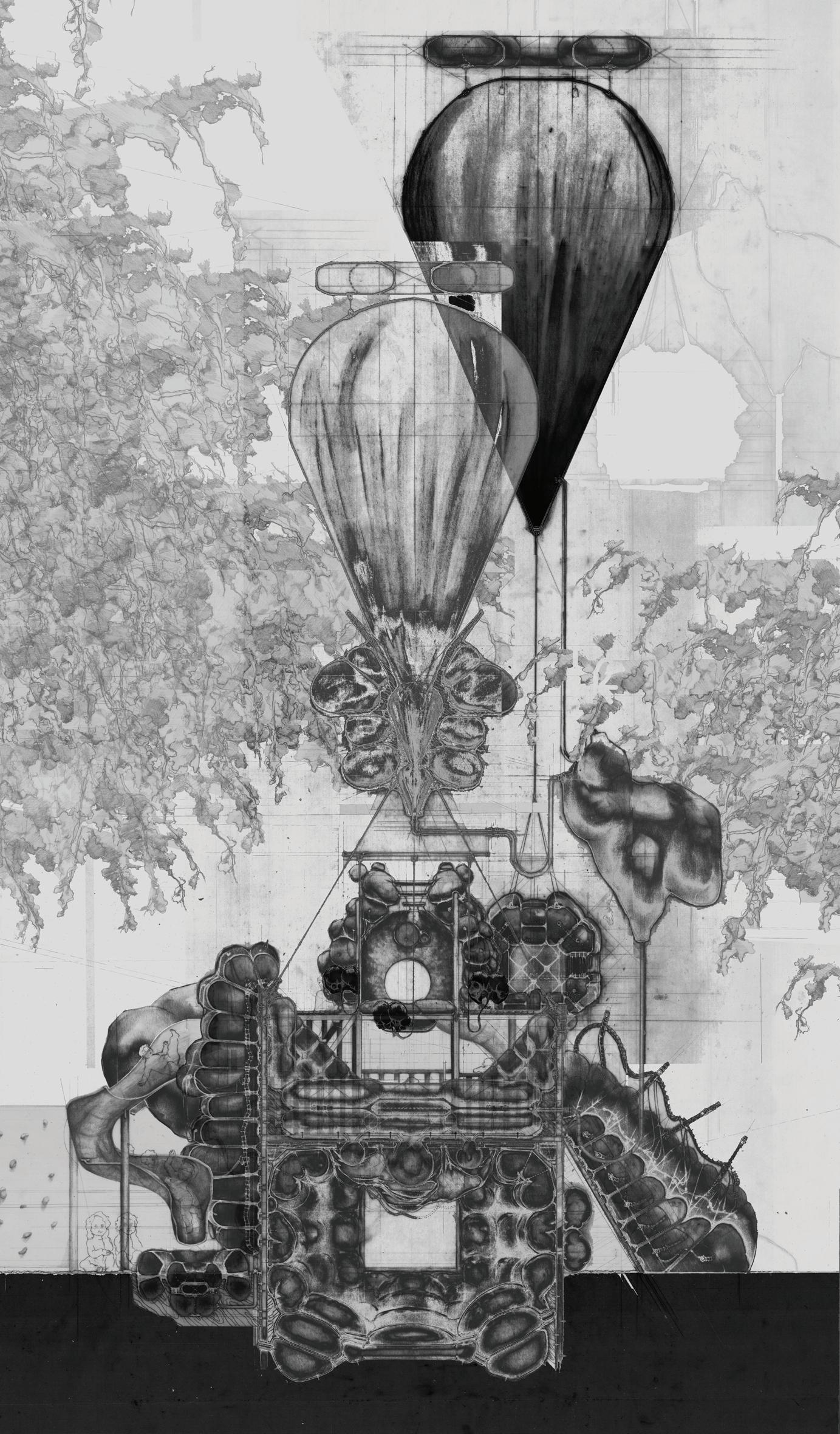



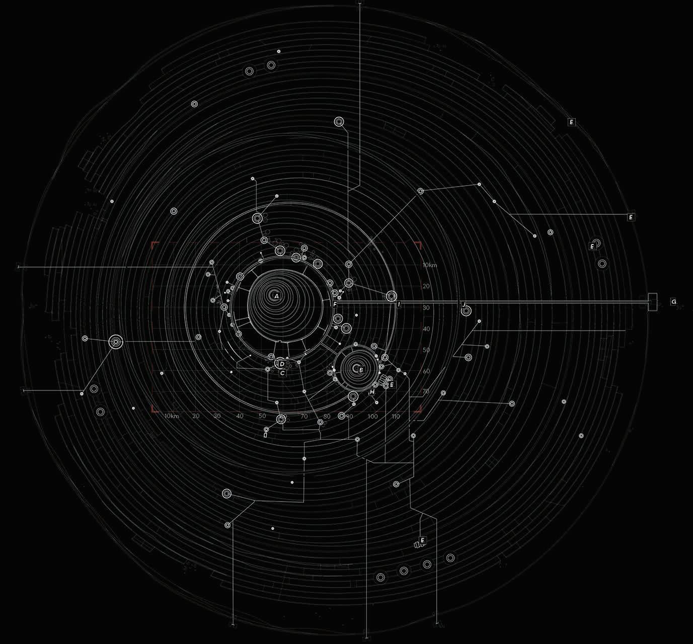
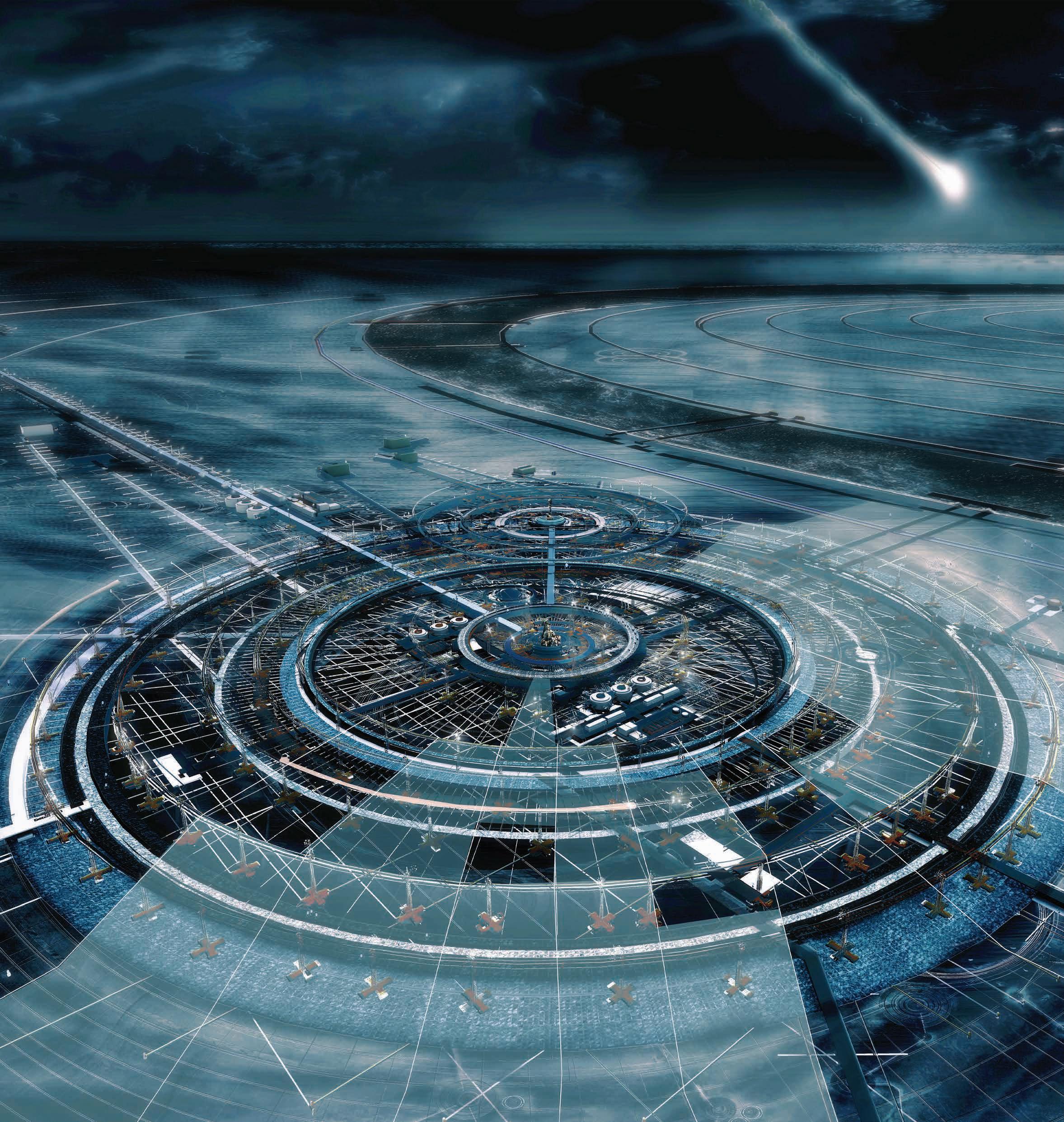
This project responds to the impact of the modern space race by proposing an architecture that retrieves and recycles the excessive debris we have put out into the Earth’s orbit. The Nemo Space Archive is located in the central region of the South Pacific Ocean that is marked as Point Nemo. This “point” represents a series of coordinates that sign-posts the most remote location on Earth; also known as the Oceanic Pole of Inaccessibility that is more than 3,000 km away from the nearest land.


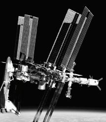
Due to this fact, Point Nemo has been used by many space organizations as the designated disposal site for decommissioned satellites. With a surface area of 1 million km², the Nemo Archive looks to monopolize the opportunity that exists in Point Nemo by capturing satellites, meteorites and other space objects that are directed here. Informed by modern graphene technology, the Archive is able to bullet-proof itself from impacting objects much like a Kevlar vest. Underneath its membrane lies the collection of space fragments that range from small commercial satellites to large space stations such as Mir. It looks to capture the International Space Station in year 2024.
Date. 21-03-2001
Ground point. 42.12° North. 12.52° East. Orbital speed. 4.760 km/s. 17137 km/h. Altitude. 400 km
DECOMMISSIONED SATELLITE

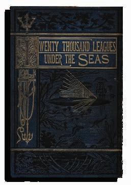
Twenty Thousand Leagues Under the Seas Amazon [1998]
Based on the same region of the pacific, Jules Verne’s Twenty Thousand Leagues Under the Seas follow the voyage of Captain Nemo, who is named after the location itself. The project takes after the captain’s ambition to invent new technologies based on observations made above and below the water of this region - incoming and sunken satellites.
143°23.6′W

17°52.6′S
Total Count: 254
Point Nemo’s ocean bed is located 4,000 m below the surface.
The site
highlights
and depths of the South Pacific region.

THERMOSPHERE
Altitude: (85 - 690 km)
MESOSPHERE
Altitude: (50 - 85 km)
STRATOSPHERE
Altitude: (20 - 50 km)
TROPOSPHERE
Altitude: (0 - 20 km)

TROPOSPHEREAltitude: (020 km)

B. GRAVEYARD ORBIT
Altitude: (39,000 - 40,000 km)
[1] - SATELLITE DE-ORBIT
Altitude: (800 - 1,000 km)
Velocity: 4.2 km/s
Temp: 600 °C
DEBRIS STATS
VO70-291353-033-008283
Date. 21-03-2001
Ground point. 42.12° North. 12.52° East. Orbital speed. 4.760 km/s. 17137 km/h. Altitude. 36,000 km

Time. 05:23:14 UTC.
REENTRY STUDY

VO70-291353-033-008283
Date. 21-03-2001
Just a few weeks ago, China’s Tianhe shuttle fell from space and produced a large amount of debris that crashed into inhabited areas.

A. - POINT NEMO (South Pacific Ocean)
[4] - LANDING
Altitude: (<10 km)
Velocity: 11.7 km/s
Temp: 880 °C
[3] - BOOST GLIDE
Altitude: (15 -20 km)
Velocity: 7.8 km/s
Temp: 1,200 °C
[2] - VAPORIZATION POINT
Altitude: (60 - 70 km)
Velocity: 11 km/s
Temp: 1,480 °C
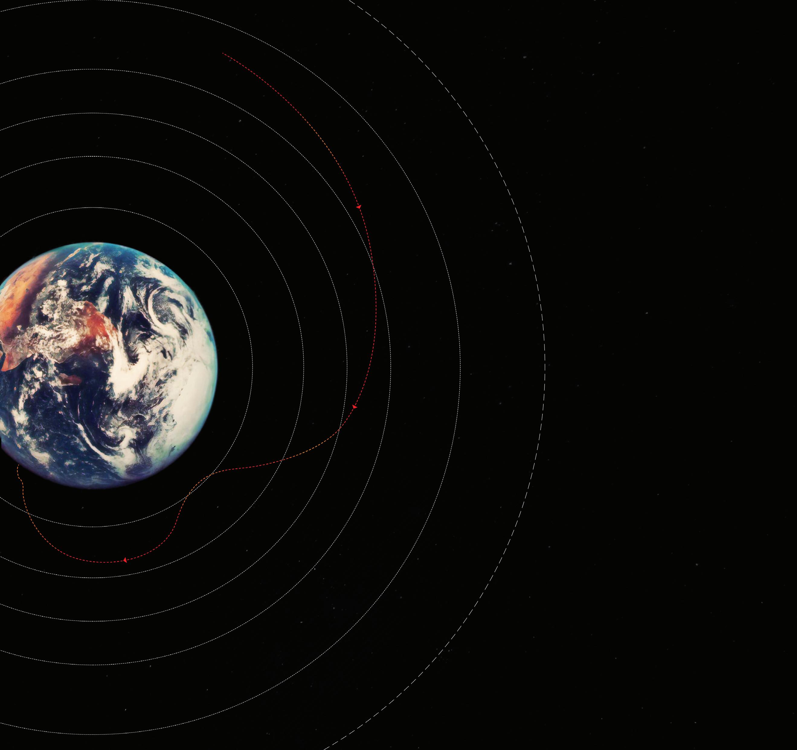
UNCONTROLLED LANDING ROUTE
CONTROLLED LANDING SEQUENCE & ROUTE
PAST SATELLITE & SPACE OBJECT REENTRY DATA

[1] - SOYUZ 1

Ground point. 42.12° North. 12.52° East. Orbital speed. 4.760 km/s. 17137 km/h.
Altitude. 36,000 km
Altitude: (170 - 200 km)
Time. 05:23:14 UTC.
Velocity: 9 km/s
Landing Mass: 2800 kg
[2] - COLUMBIA
Altitude: (60 - 65 km)
Velocity: 18 km/s
Landing Mass: 80,700 kg
[3] - CHALLENGER
Altitude: (30 - 40 km)
Velocity: 16 km/s
Landing Mass: 62,500 kg
[4] - SPACE DEBRIS

Altitude: (50 - 70 km)
Velocity: 11 km/s
Landing Mass: Varying
[5] - ASTEROID
Altitude: (10 - 20 km)
Velocity: 21 km/s
Landing Mass: Varying
My Calculations
An approximated impact force is calculated based on the ISS’s mass. The result is used in the following experiment as Impact 2.


The first experiment focuses on the dispersion of force. Three impact weights are dropped in the center of the model to depict the landing of space objects. Three classes of stationary weights on three different radius record the effects of the impact.
The three sequences describe the use of water as a medium to capture the satellite. However, the water’s surface tension must be avoided due to the high speed of impact. The fabric must break the surface tension in preservation of the space objects.
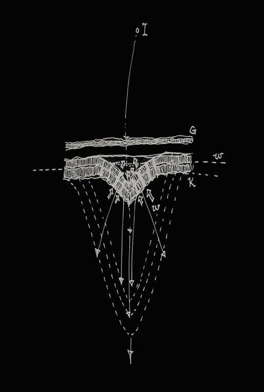
Findings show that heavy stationary masses are advantageous to have close to the center for small and medium impacts but must be moved to the perimeter when receiving large objects. Overall, distance is still the most effective variable to dampen oscillation.
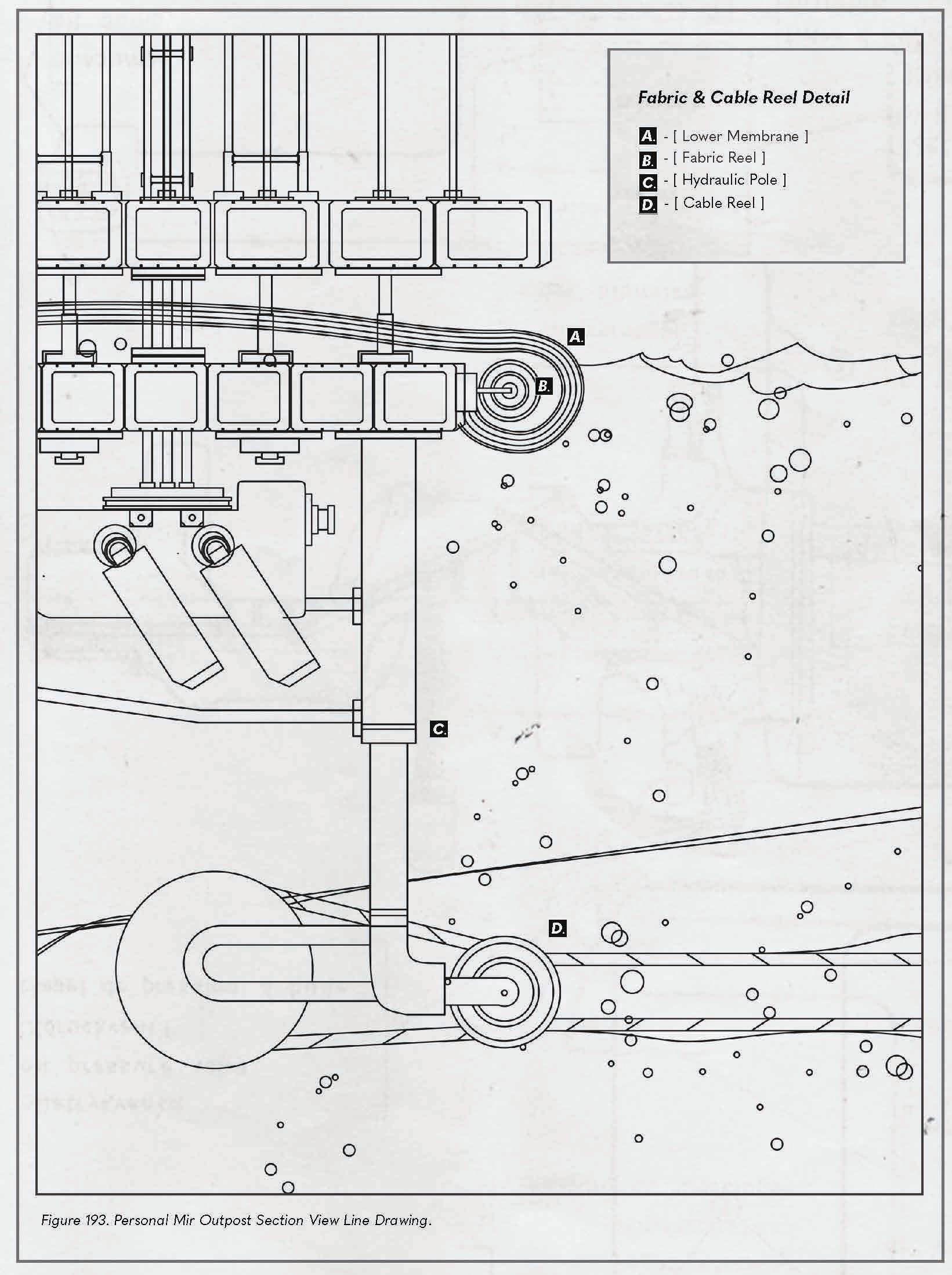
A ballast tank is used to drag the perforated fabric below the water surface. While the water is aerated, the debris will travel into the pocket of water that has little surface tension.


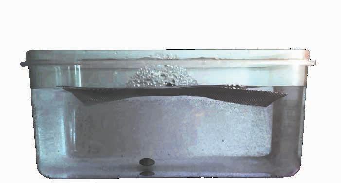

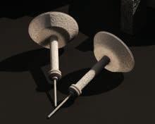
The density of water will then decrease the object’s kinetic energy. If the object does have remaining velocity and collides with the graphene, the sea anchors are responsible for providing resistance.
The pressure generated by the impact will form a high density layer of water between the object and the water surface, trapping the object and preventing fragments from escaping.


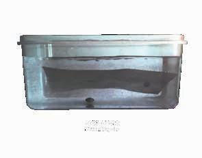
Three different materials were tested on water to deduce the most buoyant, malleable, and resistant material. The circular shape favors the dispersion of force. As the result, a combination of Kevlar (represented by mesh) and Graphene (represented by polypropylene fabric) will be used for the building’s space-object-proof skin.


 Fabric Force Diagram
Fabric Test 1 - Steel Mesh
1.
3.
2.
4.
A.
Fabric test 2 - Polypropylene
1.
3.
2
4.
B.
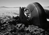
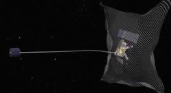
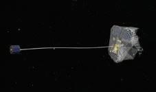
The RemoveDEBRIS satellite launched in 2018 by NASA and SpaceX is designed to return satellites and space objects back


[
]


RemoveDEBRIS satellite carries out the controlled re-entries while the Nemo Space Archive looks to capture two other types of re-entries listed below.
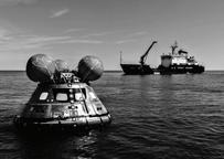
1. CONTROLLED RE-ENTRY


Reentry over a pre-determined area, region, within which the debris is to fall.
2. SEMI-CONTROLLED RE-ENTRY
Less control of the debris’ trajectory. In most cases, the general landing area can be calculated but not altered.
3. UNCONTROLLED RE-ENTRY
Undetectable objects entering the Earth’s atmosphere, they may be small remains of meteors or satellites.


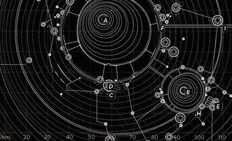


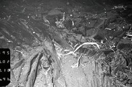


The diagram demonstrates the placement of the OTECs in relation to the thermal vents. The OTECs generate energy through the difference in water temperature between the ocean surface and the thermal vents. This is the main energy source for the building.


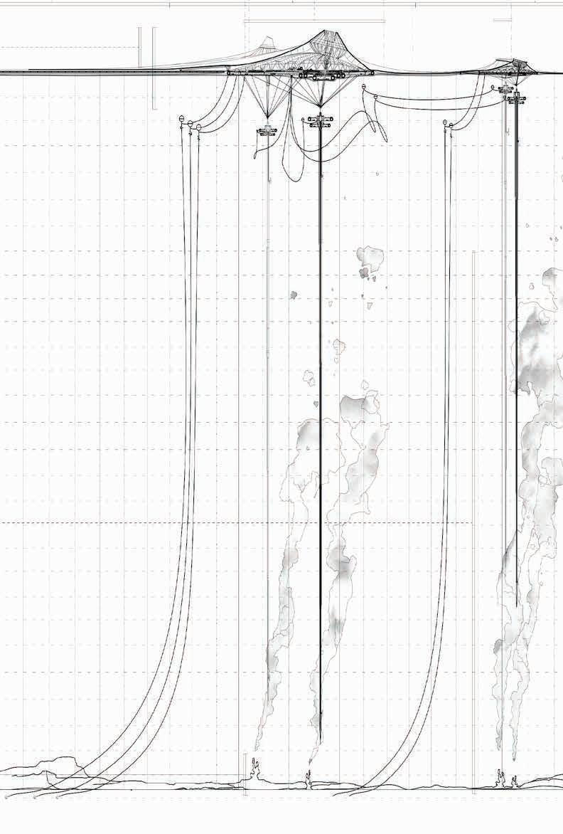







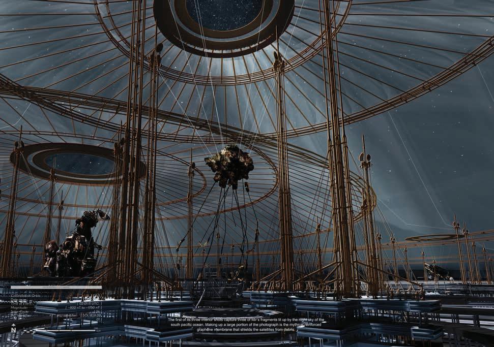

 Interior View - Graphene Fabric
Interior View - Fragment 1
Interior View - Mir
Exterior View - Capture of ISS
Columbarium Focused on Modular Construction

Site: Riga, Latvia
Design Competition Host: BeeBreeders
Team: Harry Jia, Peter Song, Lyric Barnik
July 2021
Group Work
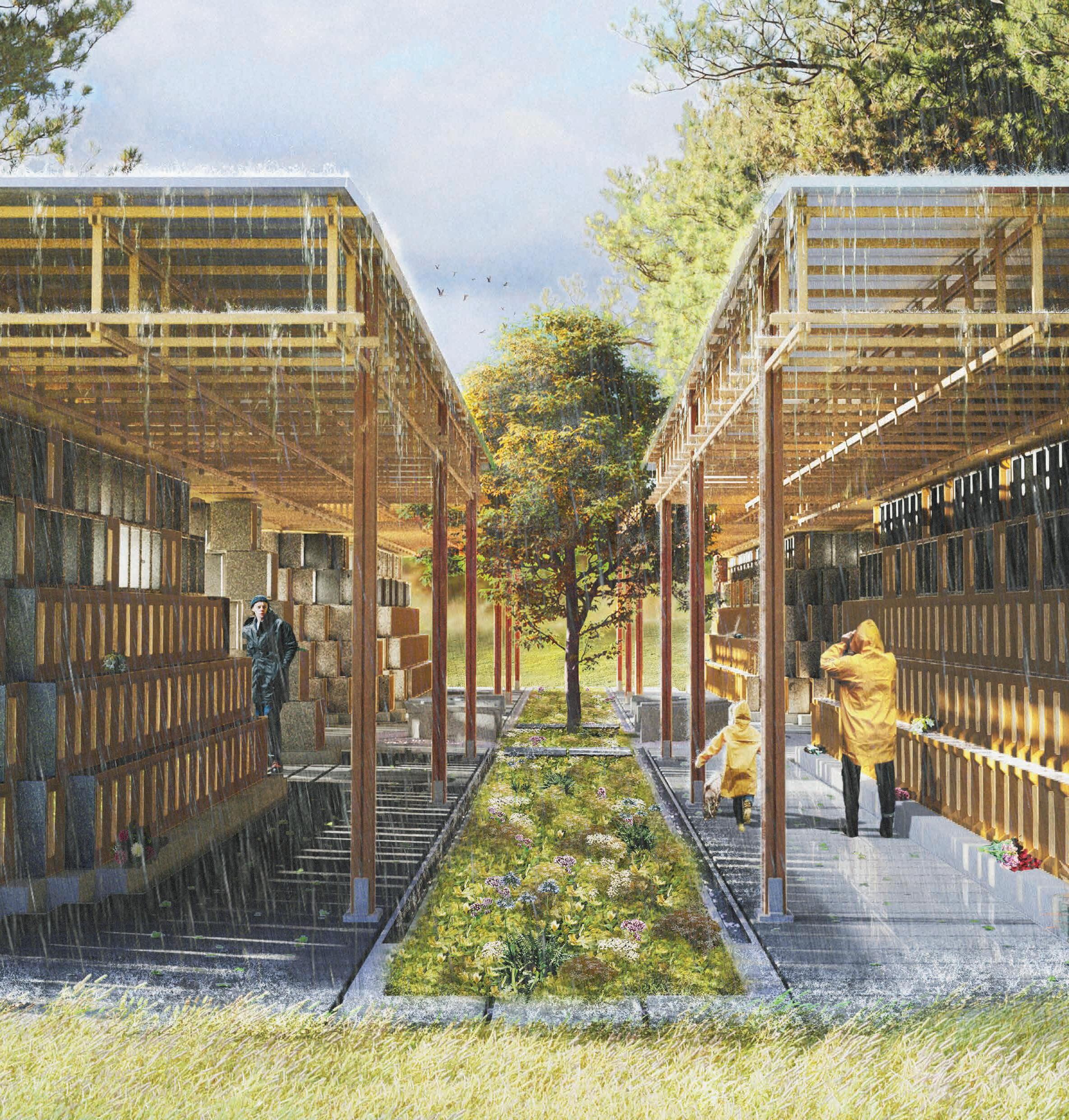
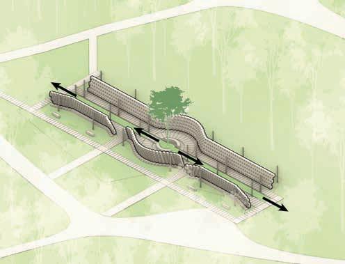
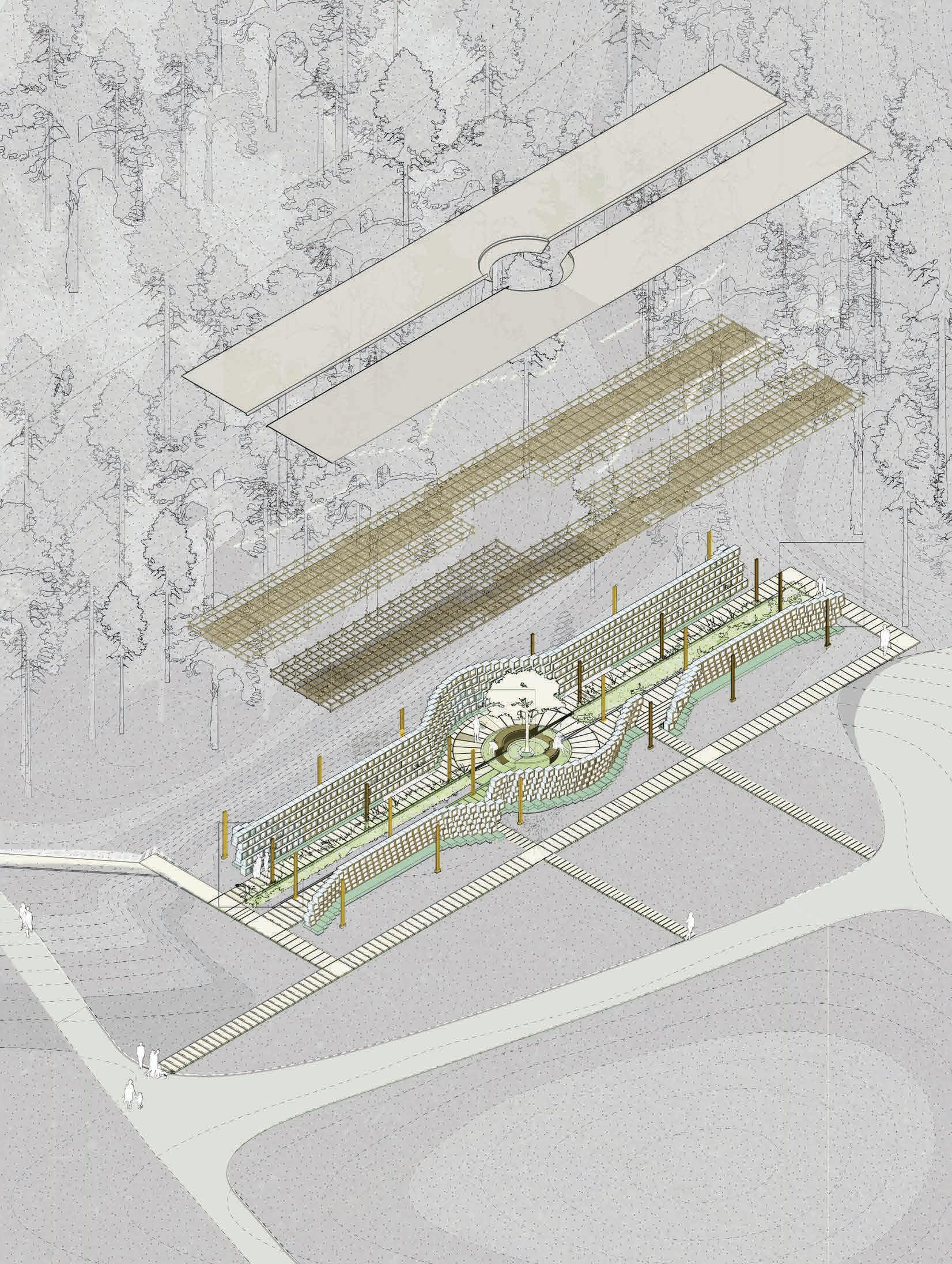
Caur Gaismu speculates on the notion of death in the light of Latvian pagan values; death is not a departure, but a return to nature. A connection to nature is paramount to offering solace in such a way. Gaismu’s design is centralized around site preservation and existing weather conditions. Dappled sunlight travel through the perforated walls into a strip of commemorative landscape which extends from the central courtyard, where niches are sculpted outwards to create a circular space of gathering around the tree that represents light and life itself. This Latvian Kaive Oak, similar to the urns, their associated visitors, and the columbarium, will be subjected to the passage of time. It is through understanding time, noticing the changing scenery that time brings, that grieving visitors may find comfort in realizing that their loved ones continue to live on within nature.
Final Render [5]
Participation Scale [1 to 5]
Due to the collaborative nature of work, a Participation Scale is used to indicate my personal involvement in each shown piece, 5 being the highest level of involvement.
Final Render [5]
Inspired by Bunker 599, Gaismu’s design coexists with the site. At the center of the journey is a courtyard, a symmetrical node inspired by the Garden Arts principle design that the forest cemetery was founded upon. All paths lead to and from this central area, a place of communal grieving and spirituality that is epitomized by an axis of vegetation and an oak tree at its core.



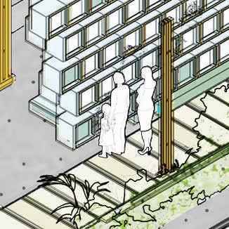
The natural phenomena of the site permeate into the columbarium: light, vegetation, and rainfall to create a respectful connection between life, death, nature and time. All three elements are reflected through the transparency of each individual niches and are physically present along the entire passage.


Modular niches are prefabricated and assembled in flexible arrangements. The niches are cast with concrete and are enclosed with wood framed glass caps. The niches themselves form the barrier between the inside and outside, symbolic of Latvian ancient pagan beliefs of death as a reunion with nature.

Through taking advantage of the site’s flat topography, the columbarium is designed to be entirely barrier-free. All niches of the bottom three rows are accessible by wheelchair.


The columbarium accommodates a total of 860 single-urn niches, 430 on each side and 86 in each row. Having five rows of niches provide an extended capacity that allows the space for expansion, as urns without regular visitation can be moved into the higher rows upon agreement with their owners as they can be more difficult to access.
Claddings
Major design decisions were made on the premise of efficient and low-carbon construction.


Slab on grade makes excavation work minimal
Security of the columbarium is maintained through surveillance cameras strategically fixed into the light-frame timber roof structure. These are out of sight for the visitors.
Bolts’ cover Niche fixings
Niches are pre-casted off site and employ modularized connections for fast and easy assembly
Composed of standard dimension lumber, the light frame timber roof is economic, light, and efficient to construct
We acknowledge this site as a place of respect, and thus, prioritized construction methods that will create minimal disturbance to its surroundings.
As the niche covers are designed to be low maintenance, intervention by columbarium staff is only required when urns need to be moved. The types of plantings on site are selfsustaining with minimal human care.
The modularized concrete niches are resilient, with an expected lifespan of 50+ years. All timber members are finished with saturating wood oil for protection against moisture and UV.
Structural
Illustrated Section [5]

ROOF CAP
TIMBER FRAME ROOF
The roof becomes a light and transparent structural apparatus, enabling natural cross ventilation.

1.Express things unsaid 2.Commemorate loved ones 3.Exit to memorial landscape

A Columbarium and


August 2022
Individual Work

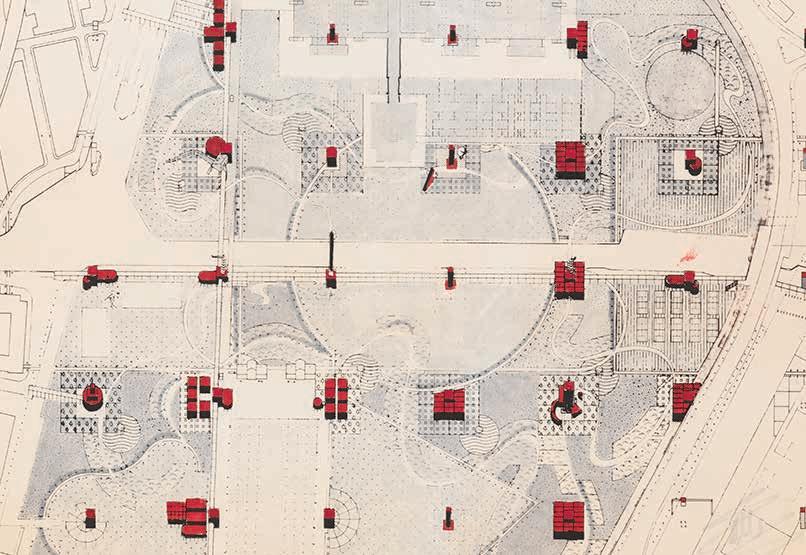
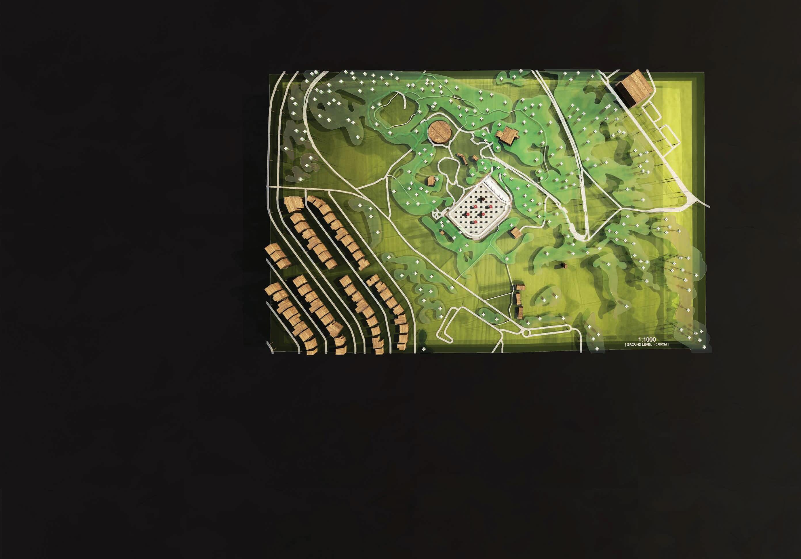
Located in the now demolished parking space in Queen Elizabeth Park, Vancouver, this project aims to address the lack of cemetery space in central Vancouver by experimenting with the integration of spaces for the dead with spaces for the living. This project began with an interest in Jacques Derrida’s theory of deconstruction and Bernard Tschumi’s Parc de la Villette. I wanted to reprogram spaces traditionally viewed as polar opposites by reassigning meaning while interweaving them through a new usage that benefits both.
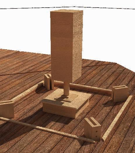
The columbarium is consisted of follies, niches, and sandpits. Each niche is accommodated by a sandpit, while every group of sandpit surrounds its folly. The follies are devices for catching rainwater. The water brings life to the children’s sand figures as their creation and joy ultimately breathes life to the site and to the niches.
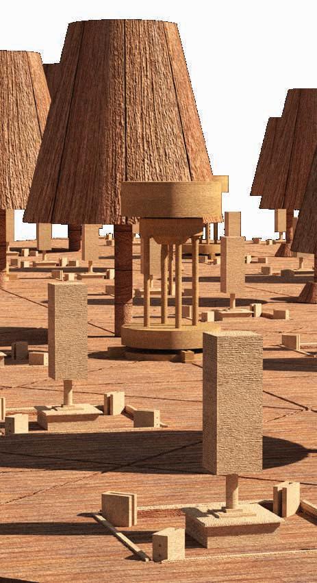
REF 1: Parc de la Villette, Paris By Bernard Tschumi [1979] Site: Queen Elizabeth Park, Vancouver Personal Interest Project Playground That Lives as One 1:200 Model - Timber, 3D Print, & Concrete



Final Plan with Highlighted niches and Follies 1:100




CHILDREN CIRCULATION




COLUMBARIUM VISITOR CIRCULATION PARK GO-ER CIRCULATION


Levitating PTSD Daycare for Refugees Children
Site: Vienna, Austria
BARC0135 - Tutors: Dan Wilkinson, Ifi Liangi
December 2019
Individual Work


Austria accepted a record of 24,000 refugees in 2016. Over half of the refugees who enter Austria are under the age of eighteen. A 14 day procedure is required prior to the acceptance and relocation of each refugee who enters Austria. In order to ease the pressure on the Austrian government, the building provides shelter over duration of the displacement period.
The Flakurm der Freude, which translates to the Flak Tower of Joy is a PTSD treatment and care center situated in the city center of Vienna for children fleeing from warzones.
The facility transmutes the city’s architectural legacy of conflict informed by Nazi and Hasburg fortifications into a space of comfort and healing through the use of pneumatics informed by The Inflatable Moment. Over the period of 14 days, the building grows and inflates and crevices at the joy of the children to reveal new spaces of therapy.
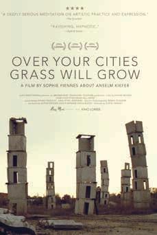
Informed by Anselm Kiefer’s war structures and The Montessori Method that assists children in communication through play, the building encourages children to play and learn in a peaceful environment adapted from war architecture.
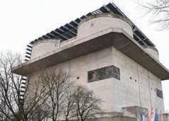
Flak Towers in Vienna [War-documentary.info] Re-purposed Flak Towers [Shutterstock]

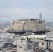

In recent years, a few of the city’s Flak Towers have been re-purposed, leading to this proposal for the remaining towers.


KEY STAGES
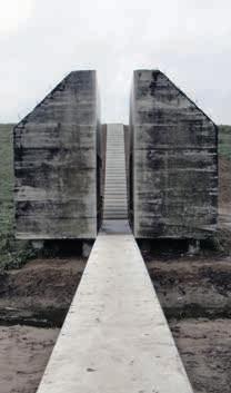
Bunker 599 [ArchDaily]
Inspired by Bunker 599, the heavy concrete structures of war are split apart to be prescribed with a new program. The use of pneumatics looks to provide a comfortable and playful environment for the children.
Diagrams based on physical models illustrate a change between states in effort to reflect the unstable landscape of war zones. Instead of modern playgrounds, they played in ruins. To ease them into the city, the building introduces them to a familiar context, but one of peace and comfort, and transformations that inspire joy and play.

Modern Air Wedge [Ergonomic Partners]

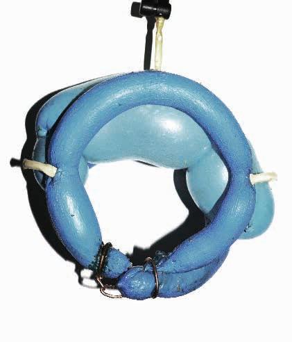
Physical Model: Heavy Duty Air Wedge - Metal, Reinforced Latex, Foam Mesh


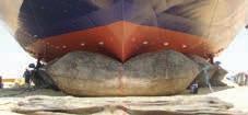
Informed by modern pneumatic lifting technologies, the model studies the combination of soft and rigid materials, catering to both the children and the Flaks.


As the children engages in activities around the building, their movements feed into the inflation of the building, generating new play-spaces.
Scale - 1:1000

HELIUM CIRCULATION
CHILDREN CIRCULATION STAFF CIRCULATION
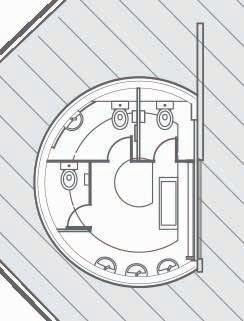
Level 01 acts as the entrance for children, teachers, and helium. Three differently colored routes show the three circulations.
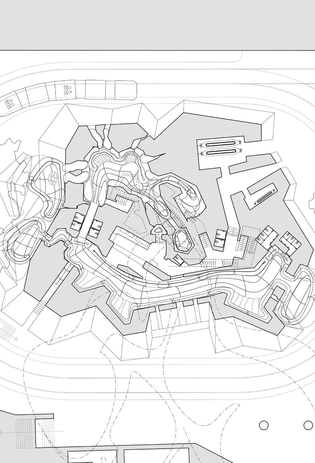

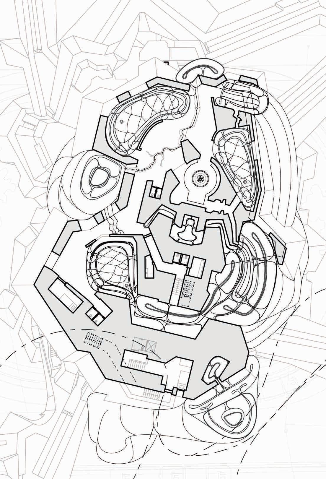
Level 05 focuses on EMDR therapy. Children are invited to participate in small groups at a time while others enjoy physical activity in the Activity Room or explore views of the city through the Outdoor View-ports informed by demolished Hasburg Bastions.
Level 10 is outdoor-focused and introduces the children to a camping experience. They sleep in semi-outdoor chambers either with other children or with the staffs in the Share Sleeping Chamber.
Pneumatic Fitted Playground for Heightened Spirit
Site: Coram’s Fields, London, UK BARC0097 - Tutors: Dan Wilkinson, Ifi Liangi
September 2019
Individual Work


In The Bible, it is said that the moment that the forbidden fruit had left its stem, Adam and Eve would forever descend into human flesh. I was inspired by Peter Paul Rubens’ The Fall of Man to take interest in our desire to return to a state of spirituality.


In effort to undo the action of Adam and Eve, I injected helium into inflatables to return the Forbidden Fruit back onto its branch. With time reversed, the Garden of Eden returns to its original form.


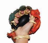


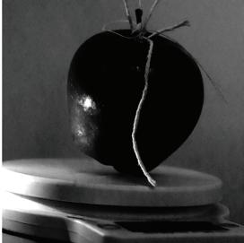

As the bible describes, Eden has no substance and Adam and Eve are spiritual beings without physical presence. This inspired the objective to bring about spirituality through the reduction of physical weight.
The Inflatable Moment’s lightweight structures inform the reduction of physical effort through the use of pneumatics.

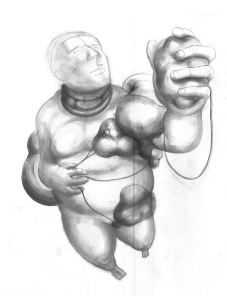


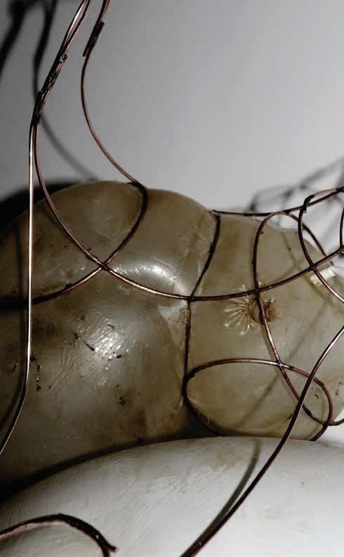
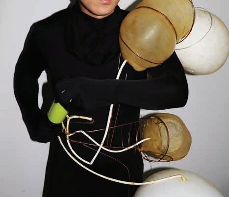
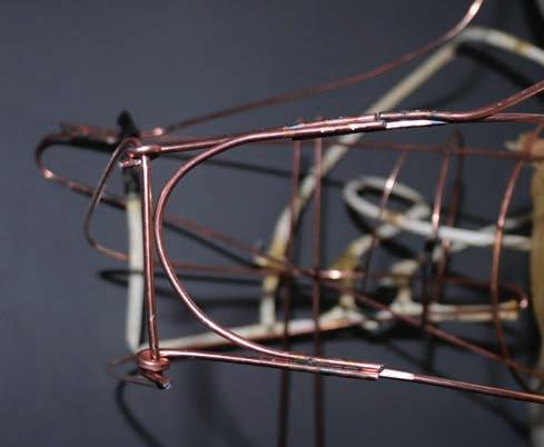

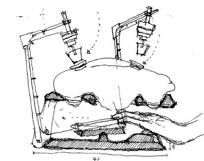
A machine that would reduce the effort of pumping through the use of a trigger mechanism. Through lessening physical effort, we can focus more on our spirit.

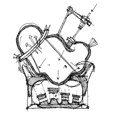

Informed by the Bible, the rib is the beginning of our physical form. It allows you to control the amount of airflow to pneumatics attached to each body-part. This gives you control of how much weight to reduce depending on your weight and activity.
Coram’s Field is a playground for children under the age of nine. You must be accompanied by a child in order to enter.

the injector by pushing up the locking mechanism. Once unlocked, the passage way is opened to allow helium to be dispersed into air channels.


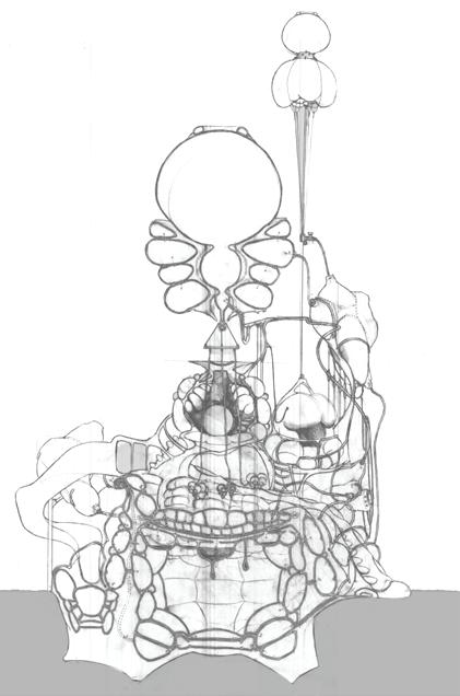

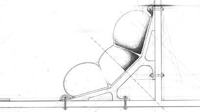


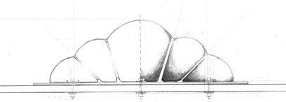

The diagram works with the battery powered centrifugal pump that takes in water and discharges it with high pressure.

They become the children of Eden as their bodies are lightened by the pneumatics and spirits heightened through play.
DETAIL 3

