HOME PROJECT
 KLaudija Lukosiunaite
Portfolio Semester 2
F127452
KLaudija Lukosiunaite
Portfolio Semester 2
F127452
Potential Client 2: Photographer
Potential Client 3: Photogrammetrist
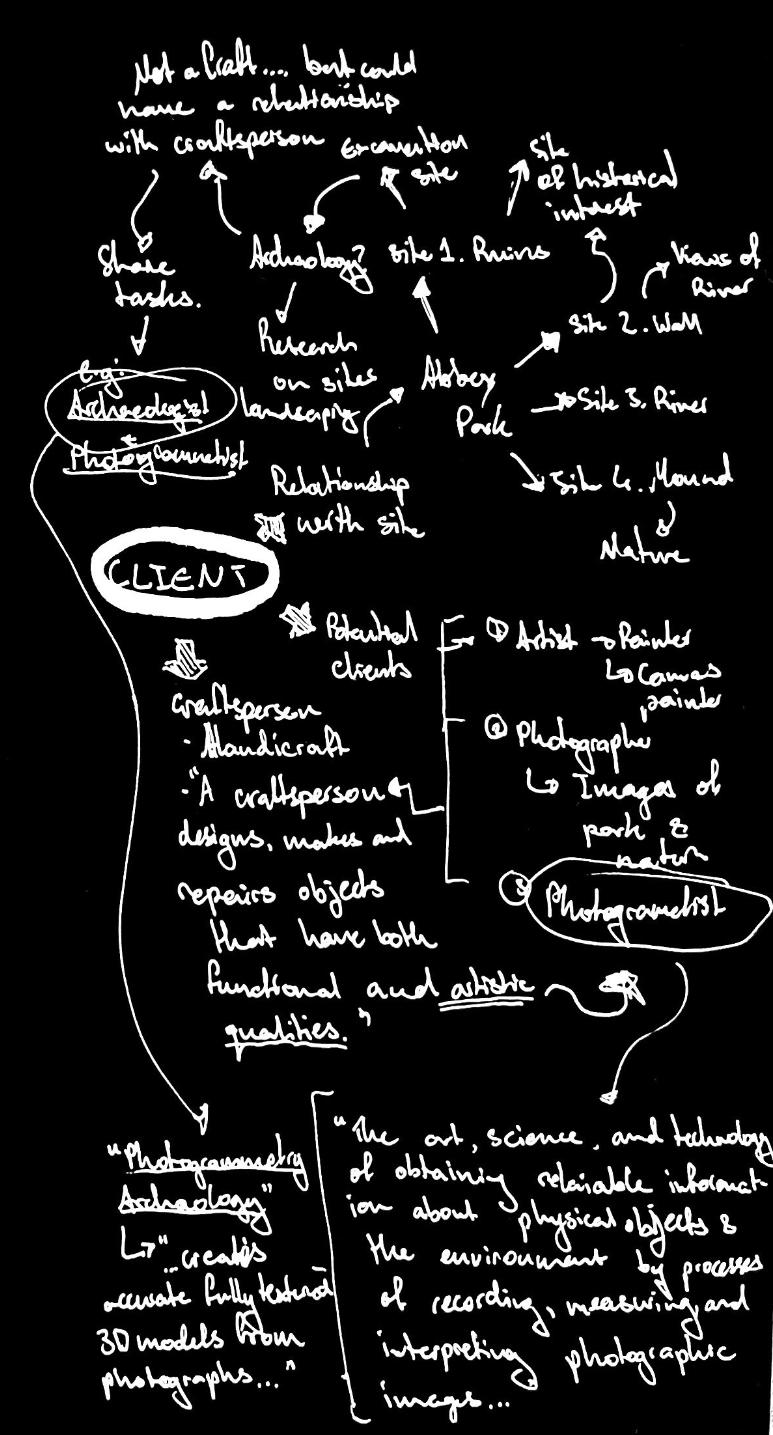

Client: Photogrammetrist “Photogrammetry is the art, science, and technology of obtaining reliable information about physical objects and the environment through processes of recording, measuring, and interpreting photographic images and patterns of recorded radiant electromagnetic energy and other phenomena.” (Wolf and Dewitt, 2000; McGlone, 2004)
Photogrammetry is most often used for surveying and mapping, but has also found its uses within art, such as digital pieces and even 3D printed replicas of objects & places.
CONTENT
CLIENT
INITIALBRAINSTORM
01 02 03 EXPLORATION DEVELOPMENT FINAL DESIGN 04 PAVILION
Potential Client 1: Landscape Artist
01 CLIENT OVERVIEW CLIENT CASE STUDIES CLIENT ANALYSIS SITE ANALYSIS PRECEDENT STUDIES CONCEPT CONCEPT MODEL CORE DESIGN REVIEW PLANS ELEVATIONS SECTIONS ISONOMETRIC PERSPECTIVES PHYSICAL MODEL 01 02-03 04-05 06-09 10-13 14-15 16-17 18-19 20-21 22-23 24-25 26-27 28 29 30 31
EXPLORATION
PHOTOGRAMMETRY CASE STUDIES
Interview with Digital Artist:
What sort of work do you do with photogrammetry (in terms of mapping out places, site planning, any form of art production etc.)?
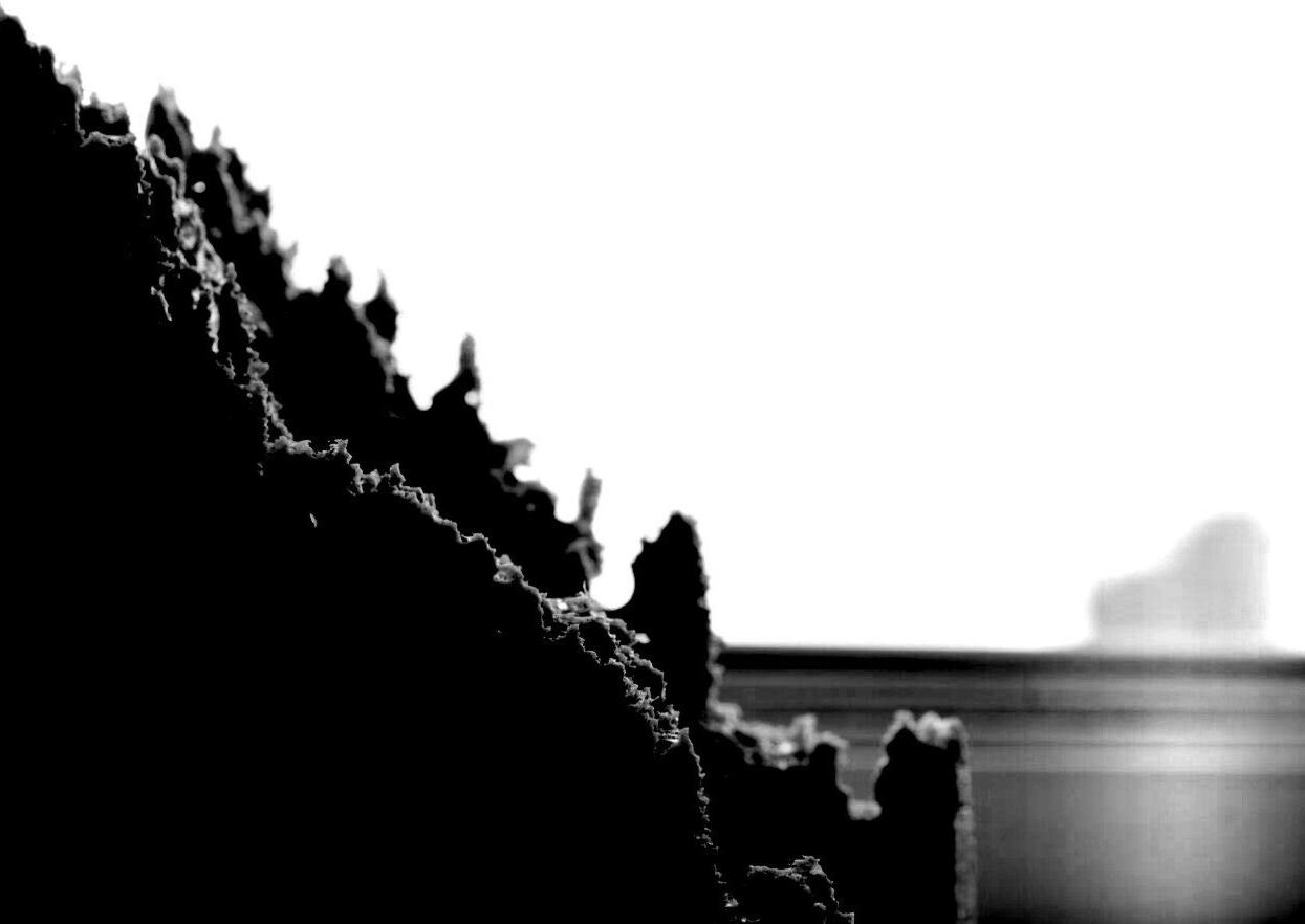
- “Well, actually I am more interested in the potential of photogrammetry and LIDAR technologies in terms of artistic and educational purposes than in their capacities of perfect documentation. So, love to have a digital and distorted collection of the places and pieces of places which move me in some way.”
In terms of the work you do in photogrammetry, do you have a certain average day work schedule?
- “My daily schedule is not very regular. But usually I do most of the digital work (creating models, editing, animating and so on) in the afternoon. My most recent project is a video to be screened on a media façade.“
What activities does your day consist of and do you work from home or within a workspace?
- “My digital work is very much related to analogue processes, such as writing, poetry, sketching and collaging. So mornings and evenings are mostly about those. And we might call the lunch time as “treasure hunt” where I would walk around and collect “pieces” from the city.”
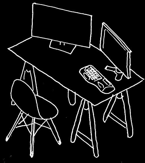
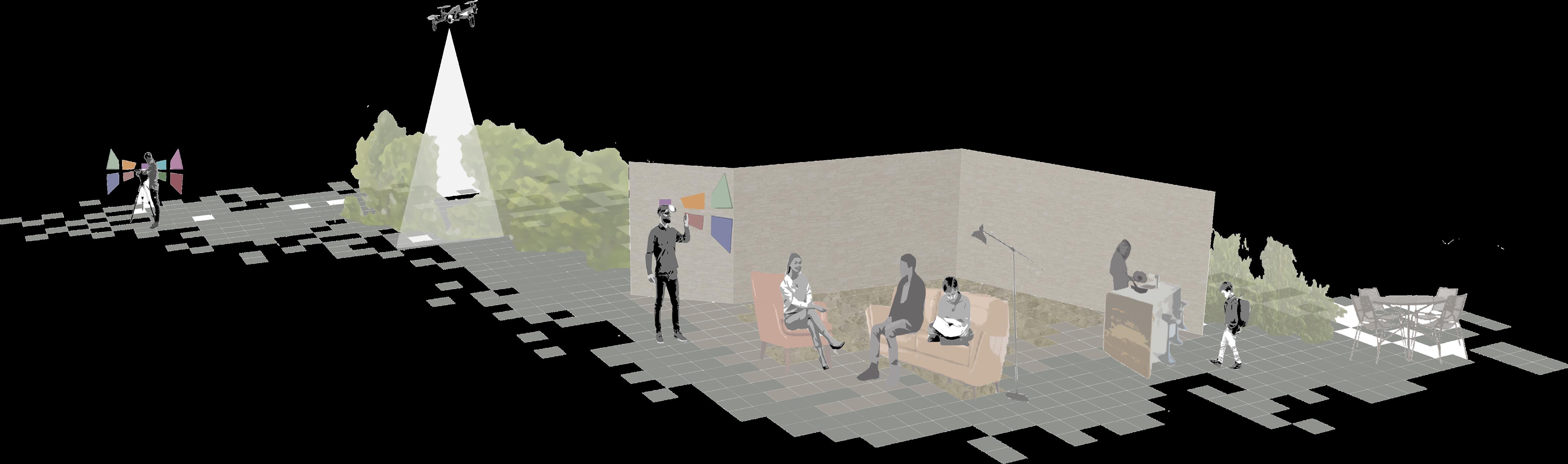
What would be your ideal work environment (in the case of having a studio to work from at home) perhaps any lighting, spatial or specific room requirements/needs and equipment?
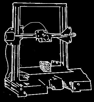
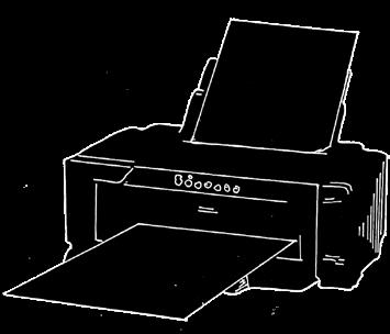
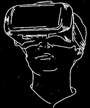
- “Ideally I would need a perfect desktop computer with maybe multiple screens, a HD projection, a low tech projection, VR headset and a large enough (for the projection and bodily experience of VR) space. would love to have a 3D printer and also a regular printer.”
- “I love spaces to be fluid and open, so furniture which is easy to move around (maybe even on wheels or sth) would be perfect. Daylight is a must, and also don’t like homogenous artificial lighting. would love to have textiles of different qualities, more transparent, more heavy etc. such as screens, room dividers and sun blocking.”
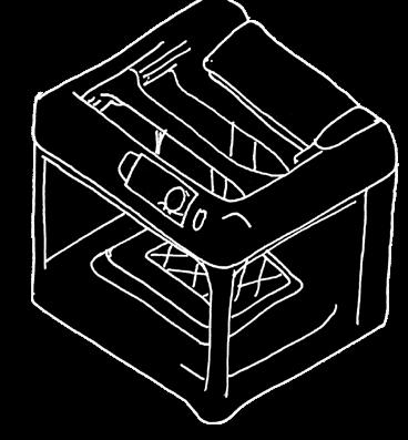
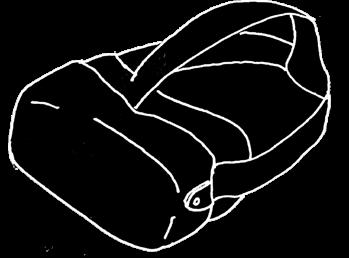
3D-Printing Photogrammetry:
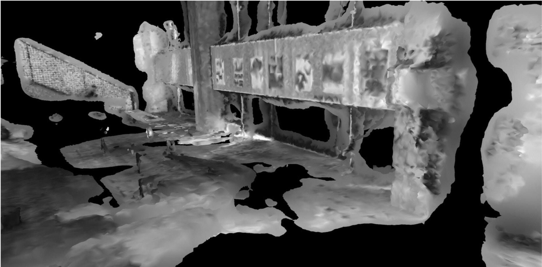
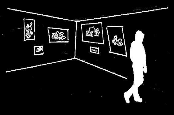
Azad Balabanian is an example of a Photogrammetry Artist who specializes in Virtual Reality.
His work caught my attention through his use of photogrammetry in order to create photorealistic 3D-printed models which replicate various places across the world.
On this page is an example of his 3D prints which had been created using Reality Capture, Blender and Ender 3 Pro as tangible replicas of his photogrammetry scans.
Hilal Menlioglu Azadux
02 03
1) (Figure 2)
(Figure
EXPLORATION CLIENT ANALYSIS
Daily Schedule - Typical Weekday
Wake up
Check and respond to emails
Visit site (most days re-visiting different parts of Abbey Park)
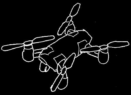
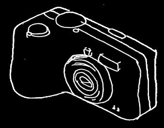
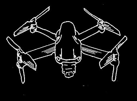
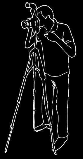
Take photos on camera and use drone for aerial images of site

Lunch break
Process gathered photos of the day into software
Open up gallery space to the public
Meetings with clients (purchasing photogrammetry outcomes)
Photogrammetry field session with archaeology students at the ruins
Process photogrammetry outcomes (3D printing, prints, vr experience)
Close, clean and prepare gallery for next day exhibition
Downtime
Cook dinner
Eat dinner and family time
Read book
Bath and relax Sleep
Family
Henry - Student:
- Age 12
- Attends secondary school in Leicester
- Requires a study desk in his room to attend to homework
- Hobbies: Reading and cooking
Client Process:
Tools: Spatial Requirments:
General Requirements:
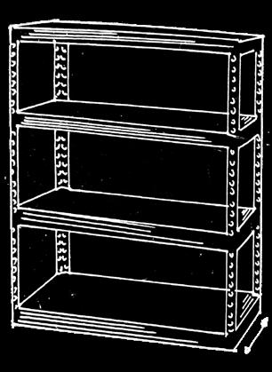
Furniture: - Workdesk
- Shelving space
- Printer - 3D printer
- Tables for 3D models
Specific Requirements:
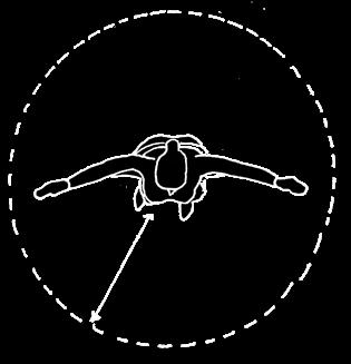
VR Space:
Dimensions: - Gallery =
-
= 7m2
- Private Studio = 25m2 - 3m2 - Ceiling height =
Light: - Workdesk
- Shelving space - Printer - 3D printer
- Tables for 3D models

John Photogrammetrist:
- Age 36
- Mainly works from home and visits sites for his work
- Requires a studio for him to work and a space for his outcomes to be exhibited by the public
- Needs a quiet space to focus on work which also access to open outdoor spaces and a space that attracts visitors
- Hobbies: Reading and cooking
Anna Archeologist: - Age 34
- Works at Leicester University as a Archeology professor
- Requires a study area to work remotely from home
- Hobbies: Gardening and cooking
-Average
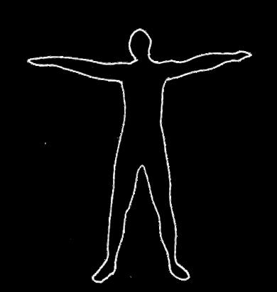
-Space Required = Diameter of 140cm
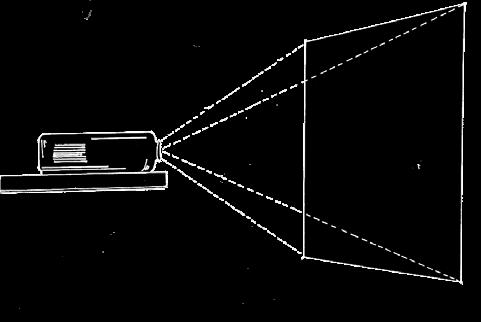
-Screen size of 100 inches (254cm)

-Wall requirement of approximately 300cm
-Distance from screen required = 310 to 338cm

depth = approximately 70 cm
07:00 08:00 09:00 10:00 12:00 12:30 14:00 15:00 16:00 17:00 18:00 18:30 19:00 19:30 20:00 21:00 22:00
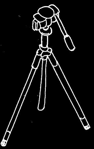
Gathering photos of site with tripod Gathering aerial images with drone Processing images through software Printing digital outcomes 3D printing model replica of digital 3D model Digital camera Tripod Drone dual screen computer/ monitor Printer 3D printer Projector VR set
Shelving Space: Wall
Storage
for Projection:
arm length = 70cm
70cm
70cm
Shelf
8m2
50m2
55m2 - VR Room
3-3.5m
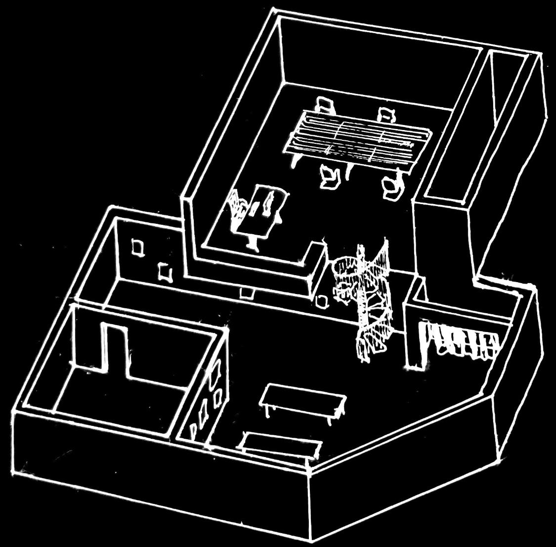
Projected art Virtual Reality experience Gallery displays 3D printed models on display Initial Studio Layout: Private studio/ workspace Storage room with shelving Visitor cloak-space VR room Staircase to upperfloor private studio Public gallery space Tables for model display 1) 2) 3) 4) 5)
04 05
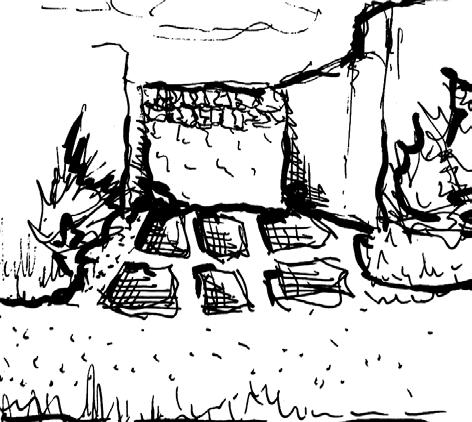
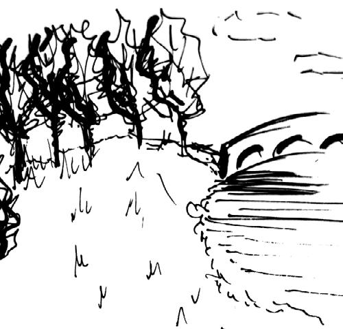
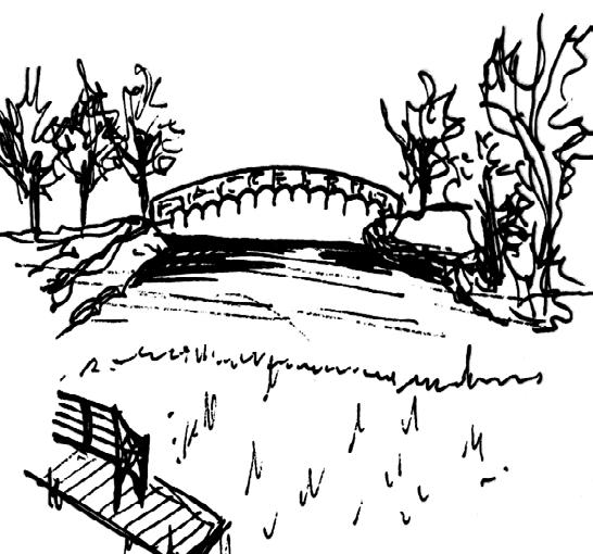
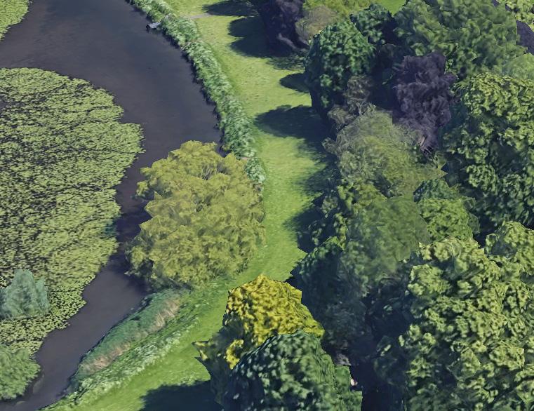
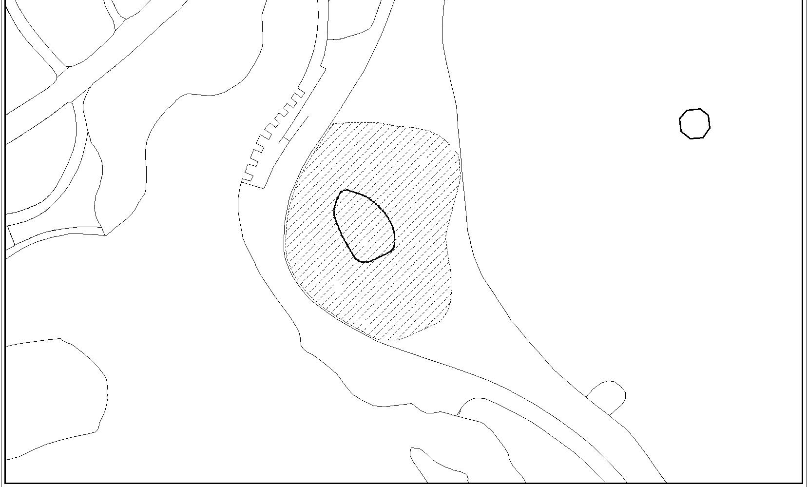
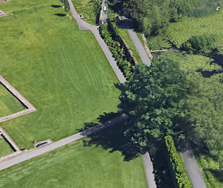
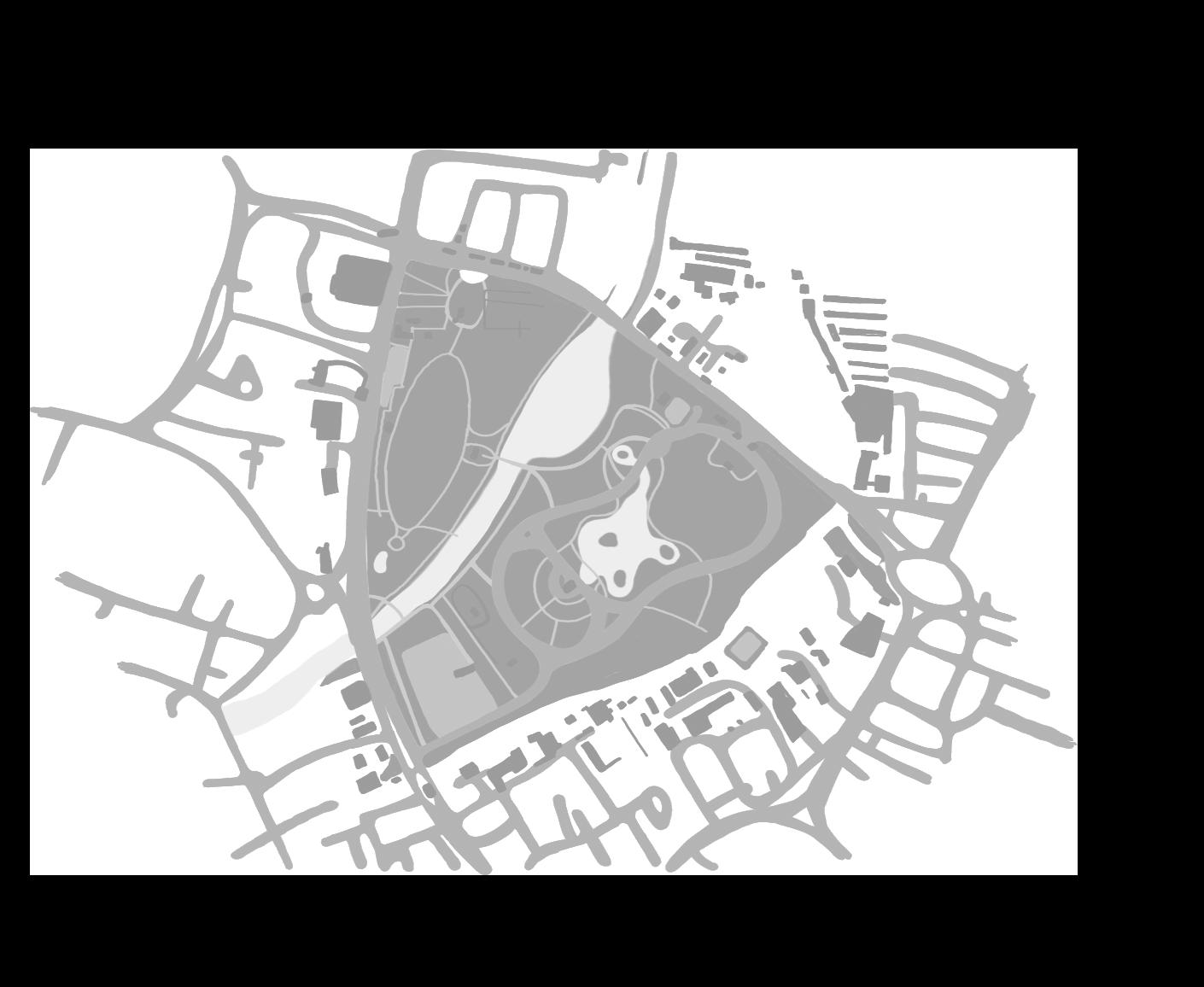
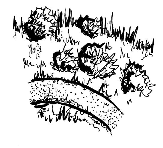
EXPLORATION SITE ANALYSIS
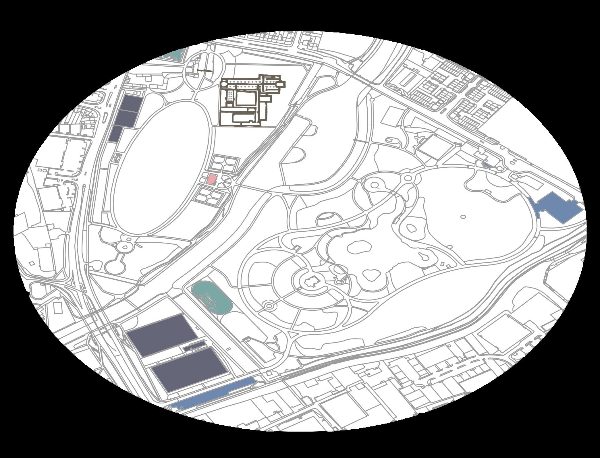
Abbey Park, Leicester Breakdown: Chosen Site:
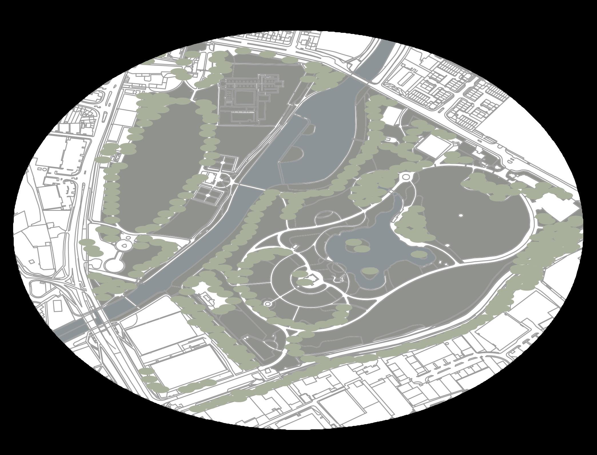
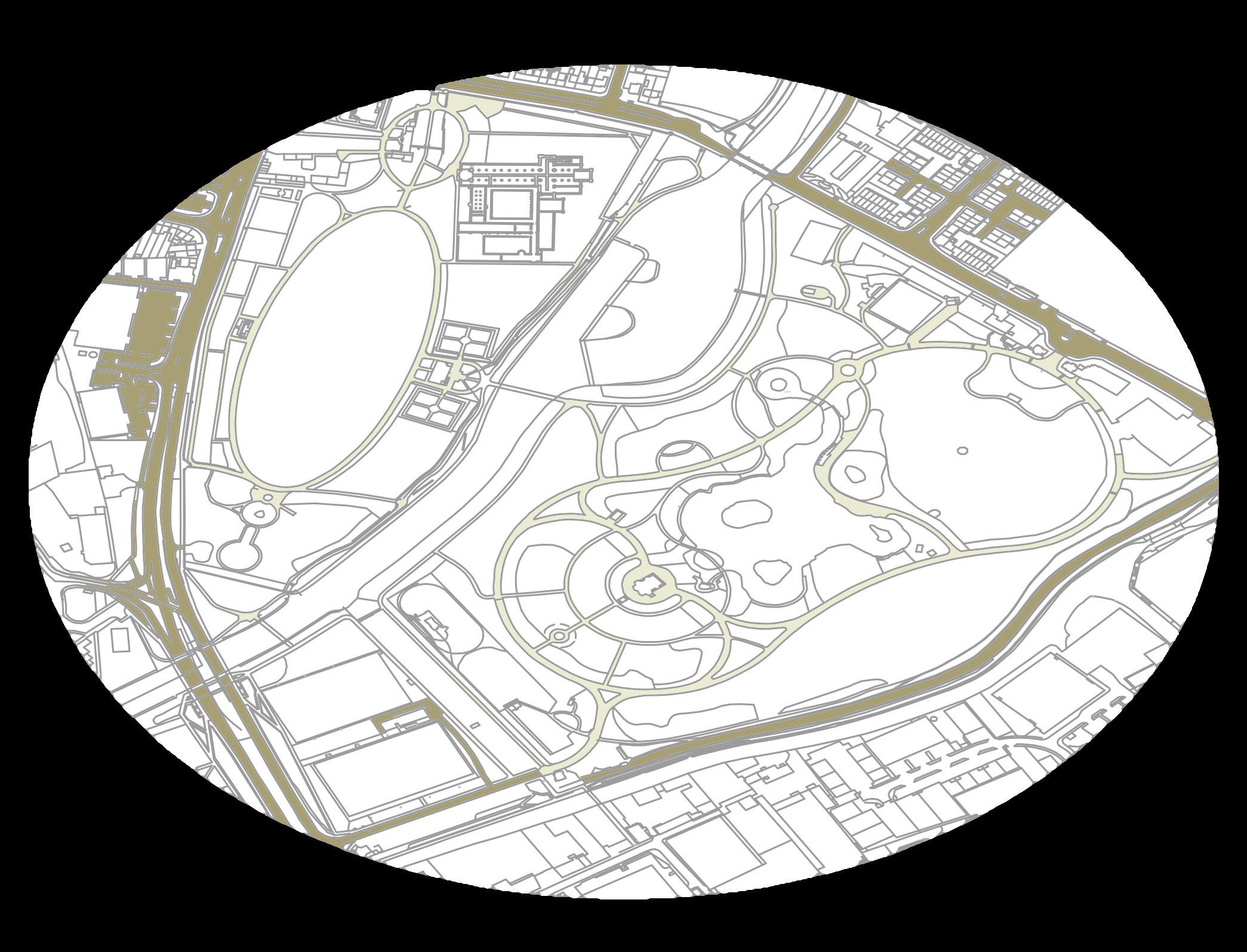
Greenery & Water
Roads and Paths
Buildings & Facilities
Key:
Key:
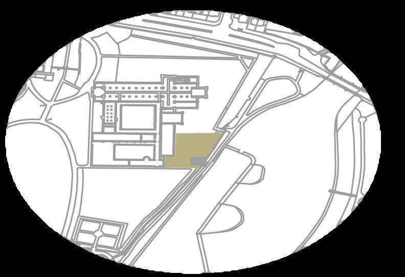
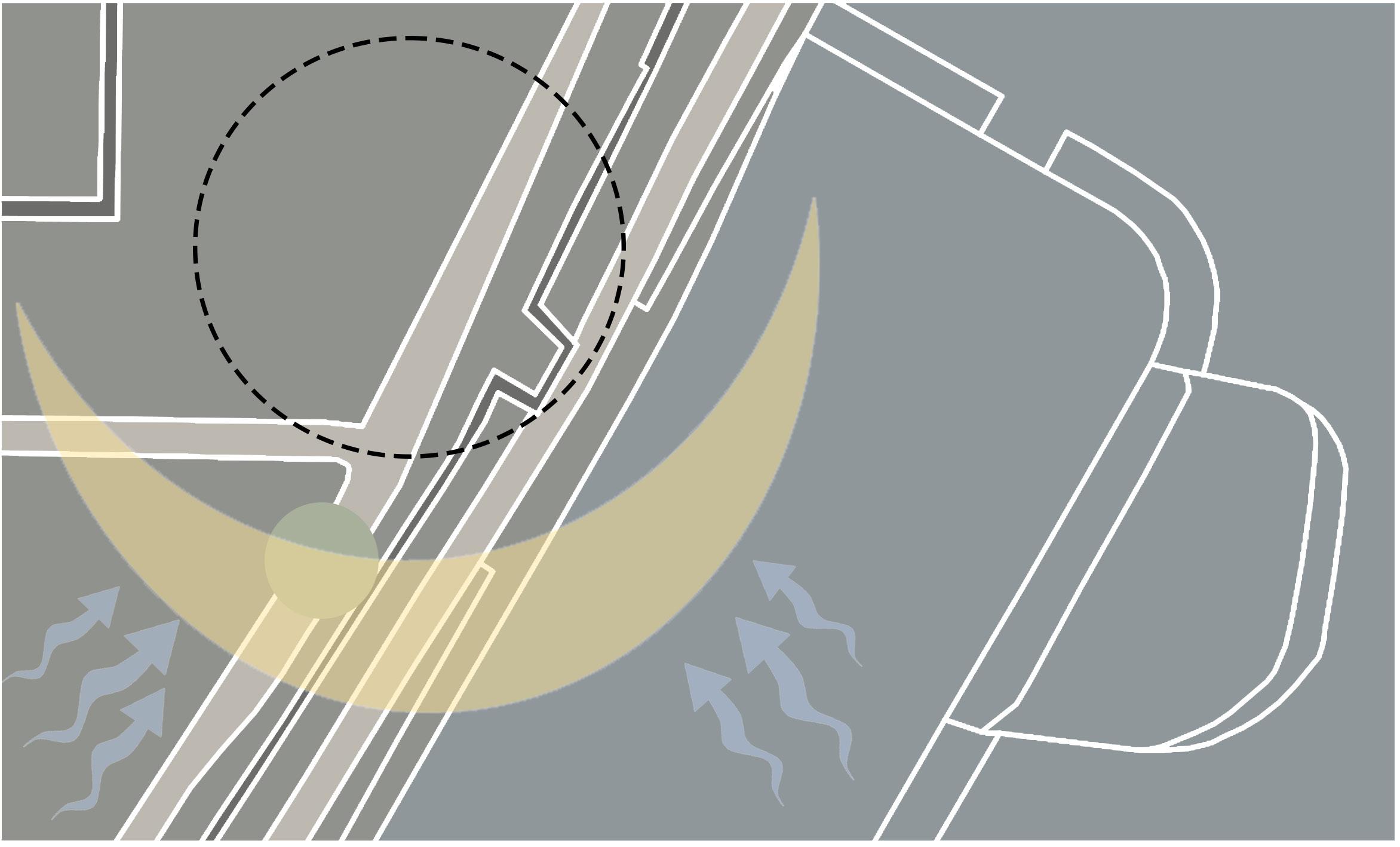
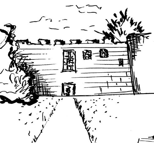
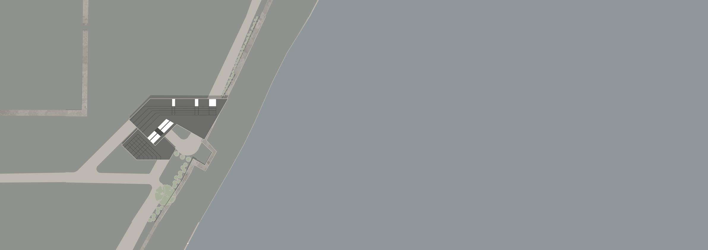
Reasons for choosing the wall:
Location: Northern part of Abbey park, by the parks ruins.
- Very accessible site through multiple pathways
- Wall provides privacy which is important for when i come to design the private spaces of the house
- Views of the river to the east and the ruins to the west
- No noise pollution which is important for my clients work, concentration, and improves the sense of privacy
- The ruins and field nearby can play an important factor to my clients work and craft
- The nearby cafe will attract visitors to the clients gallery to be able to view and purchase their work
Problems to Address:
- Invasion of privacy caused by visitors of the park so the relationship between public and private spaces will need to be considered
- Working around existing wall without directly affecting it
Proposal
Site Boundaries
Winter wind Summer wind Sun Path 1:500 5m 35m 50m
Key: Grass Water Trees Roads Paths Ruins Sports Facilities Entertainment Parking Food & Drink
06 07
EXPLORATION SITE ANALYSIS
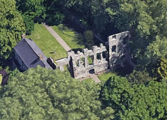
Site 1- The Ruins
- Nearby car park
- Rich Historic culture
- Easy access trhough nearby pathways
- Close to a main entrance of the park
- Existing structure which could be built upon/around
- Near public entrance
- Near a main road
- Site attracts many visitors to the park
- Complex structure to be built upon
- Cantilever could be built over the ruins
- Stone could be sampled/ similar stone used for main structure material
- Could integrate part of the ruins walls to the main body of structure
- Ruins stability may be insufficent
- Detract historical aspect of ruins
- Blocking view of space and ruins from visitors
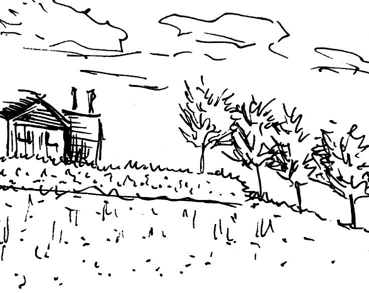
Site 2 - The Wall
- Views on the South-East side of the wall are nice.
- Site is accessible via multiple paths
- No noise pollution
- Sufficient daylight
- Public cafe nearby which attracts many visitors to the area
- Building a home may detract the existing wall
- Could block views to the ruins
- inconsistent wall height

- Vegetation grows on the walls
- Close proximity to a field and ruins can be taken advantage of for the purpose of the clients craft
- Second floor of the building can be designed so that the rooms look out over the wall to the views of Abbey Park
- The Existing wall can provide more privacy to the site
Threats
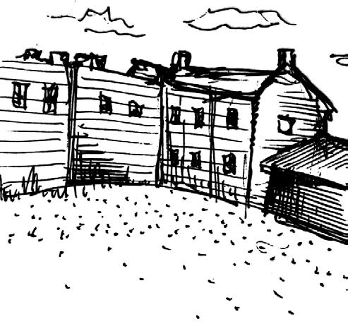
Site 3 - The River
- Nice views of river and park
- Relatively flat terrain to work on
- Shading provided by trees
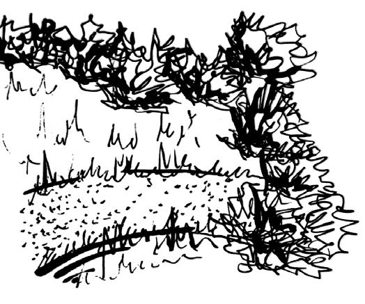
- Close to several pathways
- Noise pollution from water of river
- Terrain slopes close towards the river
- lack of privacy from public
- River attracts visitors to the site

- Could build cantilever out over river
- Deck design on river
- Introduce river flow or water as a design concept
- Make use of the sloping lanscape and nature
- Risk of flooding
- Noise pollution from river could affect clients work and home life
- River could be hazardous (for example to young children) as there are no barriers
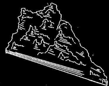
Site 4 - The Mound
Strengths
- Close proximity to river may cause the risk of flooding
- Controversy over the incorporation of the wall due to its historic heritage
- Stability of the existing wall
- Site overlaps public pathways which may need to be removed or shifted around
- Invasion of privacy by parks visitors
Weaknesses Opportunities Threats
- View of lake
- Raised ground level
- Located in a central part of the park (heart of the park)
- By park flower beds and plentiful tree coverage
- Not much privacy due to its central location
- Walkway located directly infront of mound
- Rough uneven ground
- Could create cantilevering platforms as the sites terrain has steep gradients
- Surrouding trees could be implemented to the design or used as a main deign feature/ inspiration
- Building in this side could help improve the rough, unused landscape
- Rough, uneven ground could cause issues to buildings stability and would require extra support or the need for an even manmade foundation
- Lack of privacy due to a main walkway in close proximity which could negatively impact my clients work and home life
Scale 1:500 Parking Points of Interest Access to Site Noise Pollution 5m 50m Strengths Weaknesses Opportunities Threats Parking Points of Interest Access to Site Noise Pollution Parking Points of Interest Access to Site Noise Pollution Parking Points of Interest Access to Site Noise Pollution Scale 1:500 Scale 1:500 50
Weaknesses
Strengths Weaknesses Opportunities
Strengths
Opportunities Threats
5m 50m 5m 50m 5m 50m 1 2 3 4
08 09
Peter Eisenman Iteration Grid (House VI):

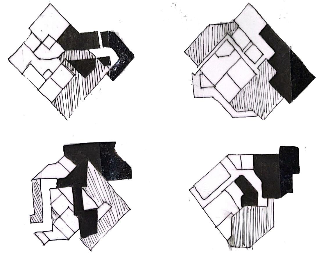
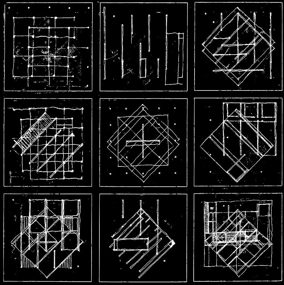
Concept for House VI:
DRAWINGS FROM PRECEDENT STUDY
Architect: Peter Eisenman
Year: 1975
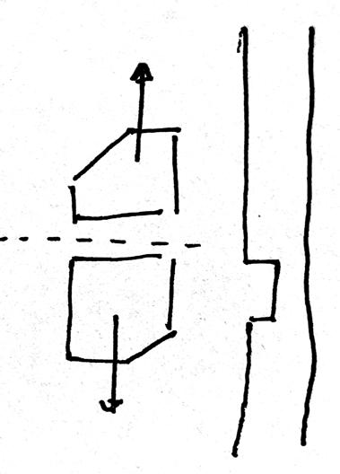
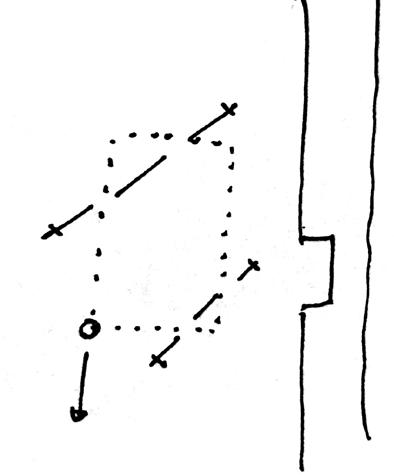
Eisenman has a deconstructivist approach to his work and most of his architectural designs follow a similar process. They start as grids, and are then itterated through shift and rotation and layers of grids, lines and rectangular elements.
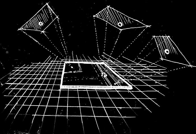
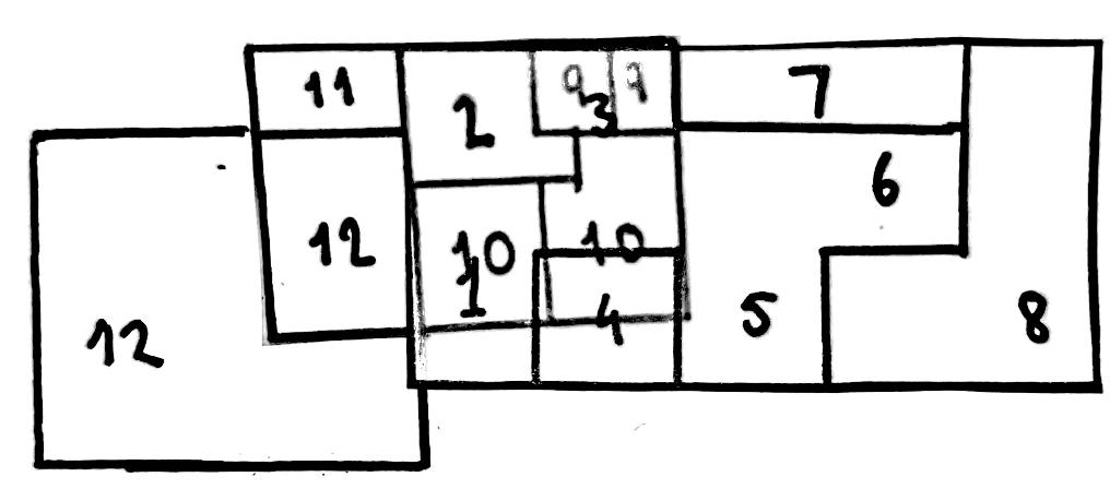
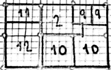
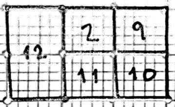
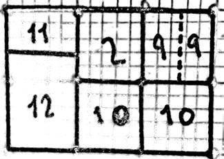
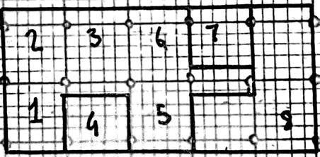
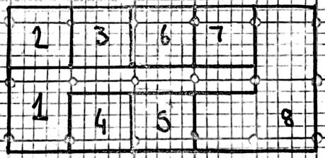
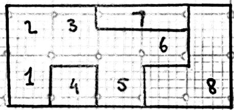
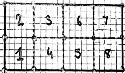
Given that photogrammetry softwares contain square grids in the basis of forming perspective visualisations, I wanted to take this ‘grid’ concept as a starting point for my design process and the basis for my floor plans.
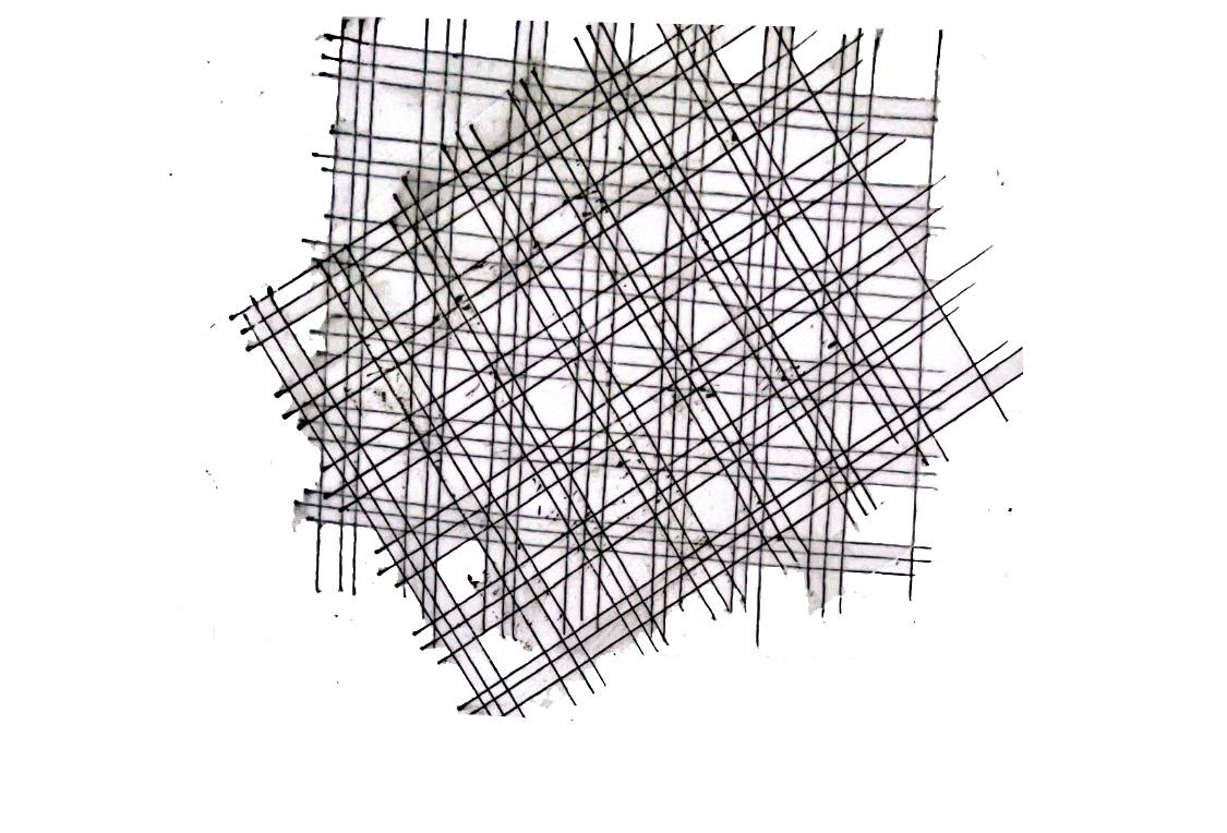
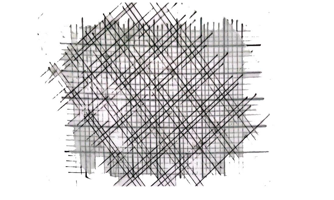
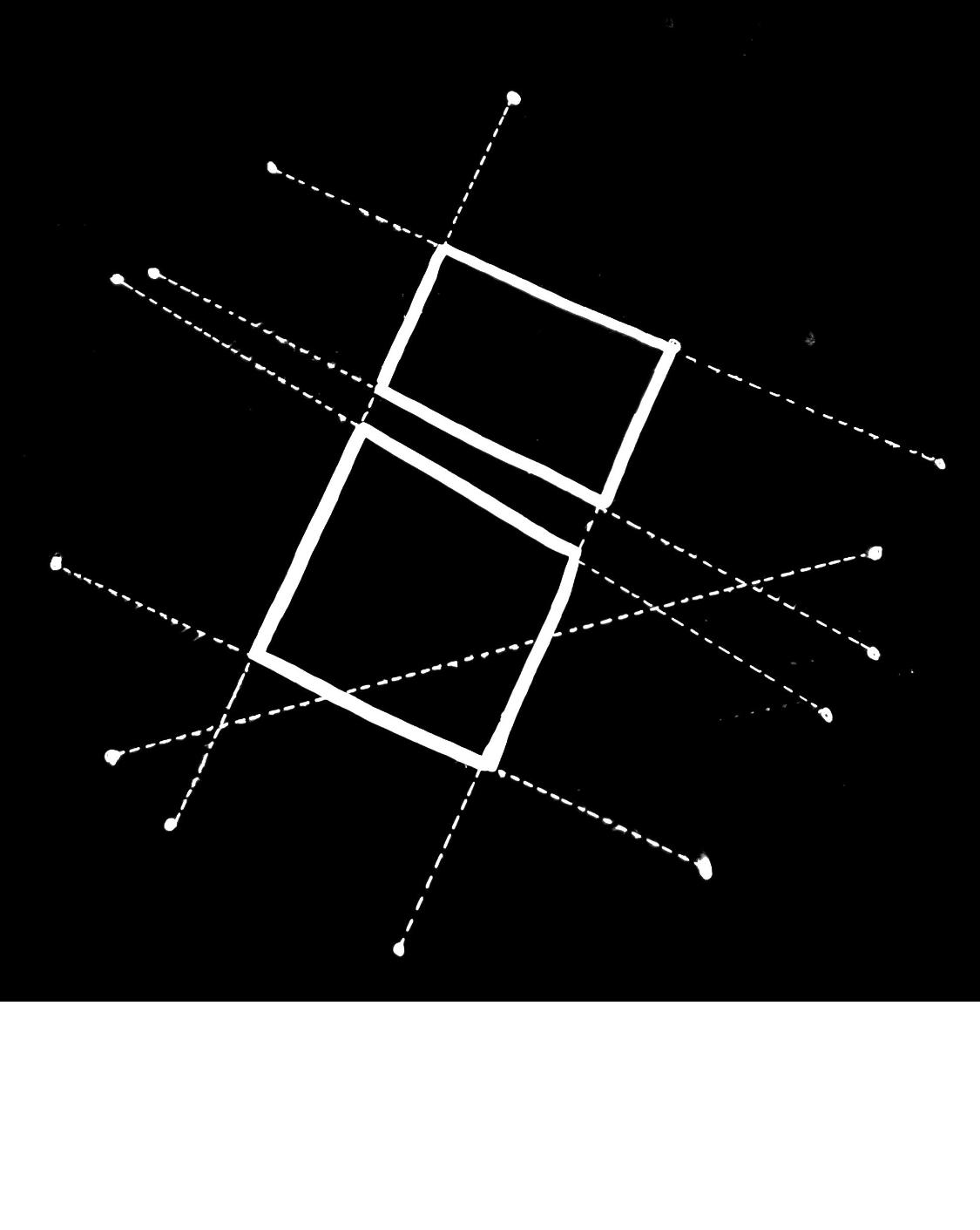
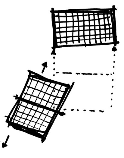
Overlapping Grids:
Exploring Eisenman’s plan drawings for the House VI, found myself wanting to work in a similar format, in which would take two different grids and overlap them. Similarly to Eisenman’s process, would then rotate these grids whilst they overlap eachother so that they no longer line up. By doing so, am then able to distinguish the different shapes that start to form, which can be used to create new spaces through floor plans, which can also be further iterated by intersecting lines.
This is a process explore in my ‘Drawings from Precedent Study’ section.
Creating Plan Layout (using grid):
Addition of the ‘wall’ for context


1) 2) Ground floor Garden Key: Upper floor(s)
First
Ground
1 Entry 2 - Staircase 3 - Living 4 - Toilet 5 - Kitchen 6 - Dining 7 - Storage 8 - Garden 9 - Bathroom 10 - Bedroom 11 - Study/ Guest room 12 Workplace/ Studio Overlapping Floors 10 11
Floor
Floor
(Figure 3)
(Figure 4)
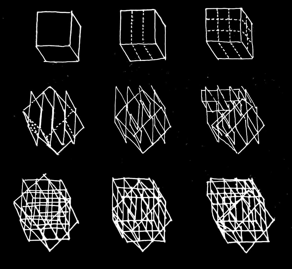
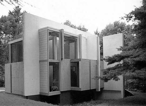
Concept for Casa da Musica:
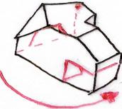
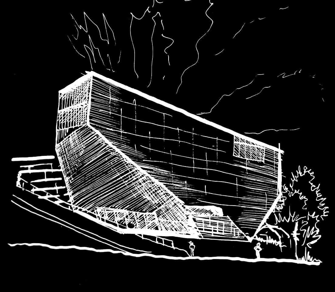
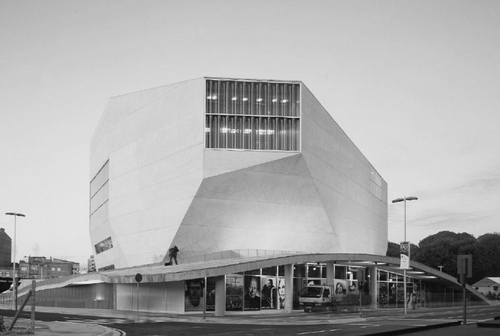
MODELS FROM PRECEDENT STUDY
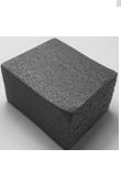
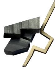
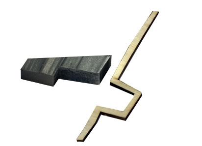
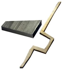
Exploring OMA’s form development for the Casa da Musica, wanted to take a similar approach of cutting and removing pieces of a shape to create a faceted form. By using three-dimensional quadrilateral shapes, namely cubes and cuboids, began to carve at their edges to create new geometric forms then began to remove larger chunks to explore how much the form is prone to change.

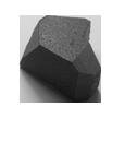
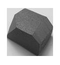
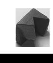
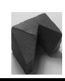
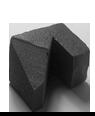
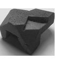
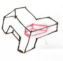

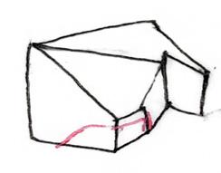
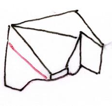
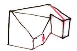

This is something explore in my ‘Models from Precedent Study’ section.
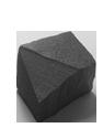
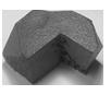
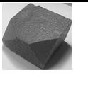
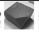
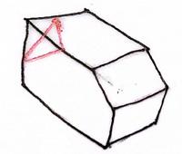
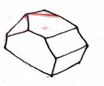

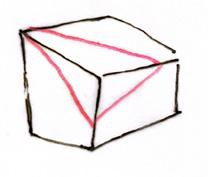
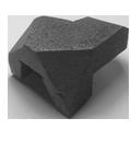
Outcomes of model development
1) 2) 3)
12 13
This process of cutting into a foam block to create new volumes will be something I explore in my project development stage.
(Figure 5)
(Figure 6)
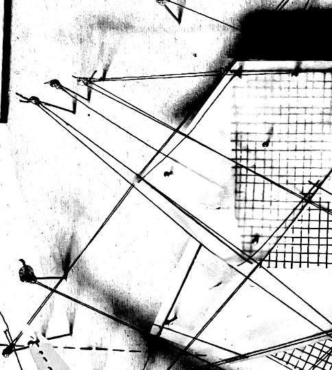
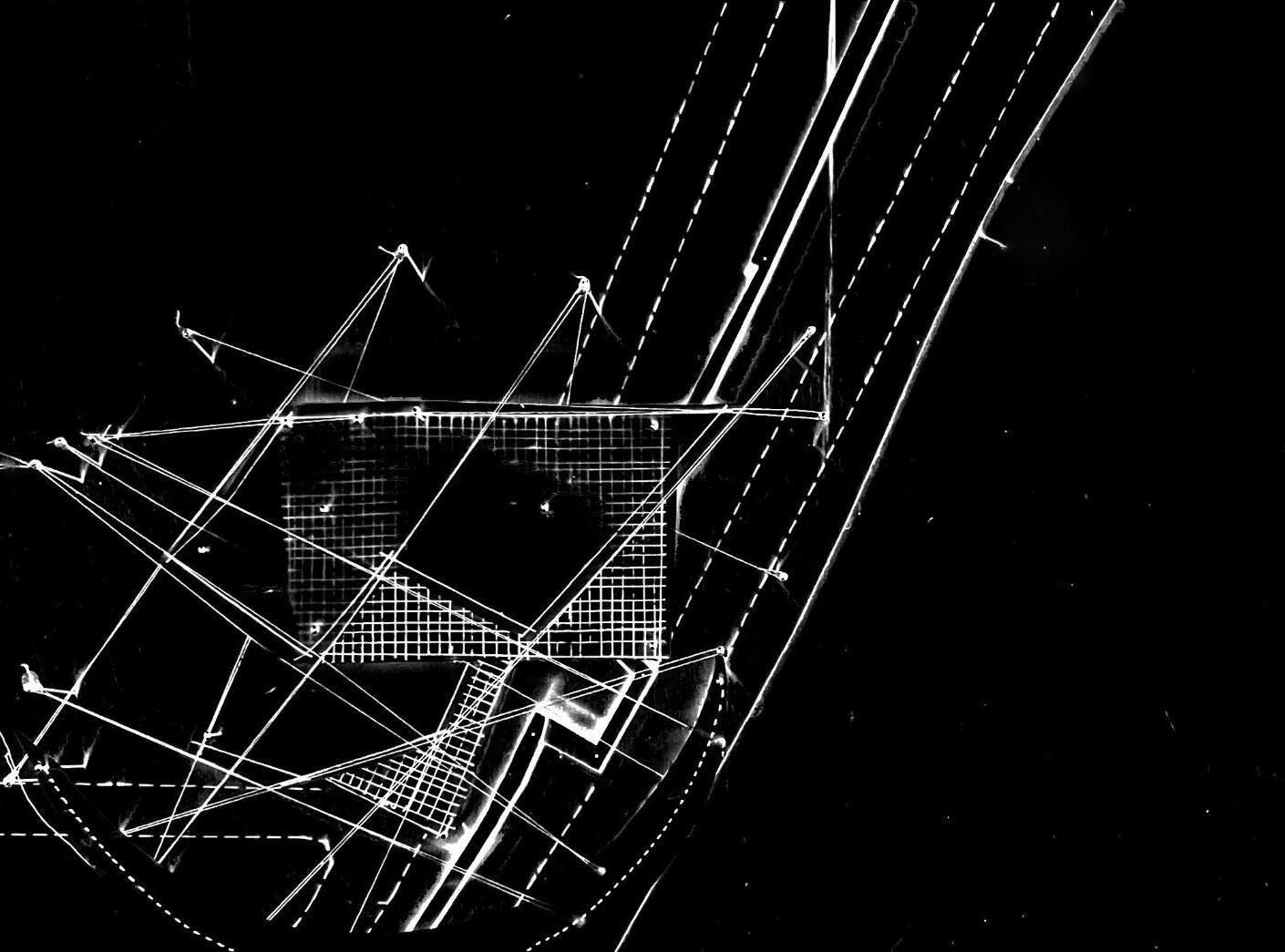
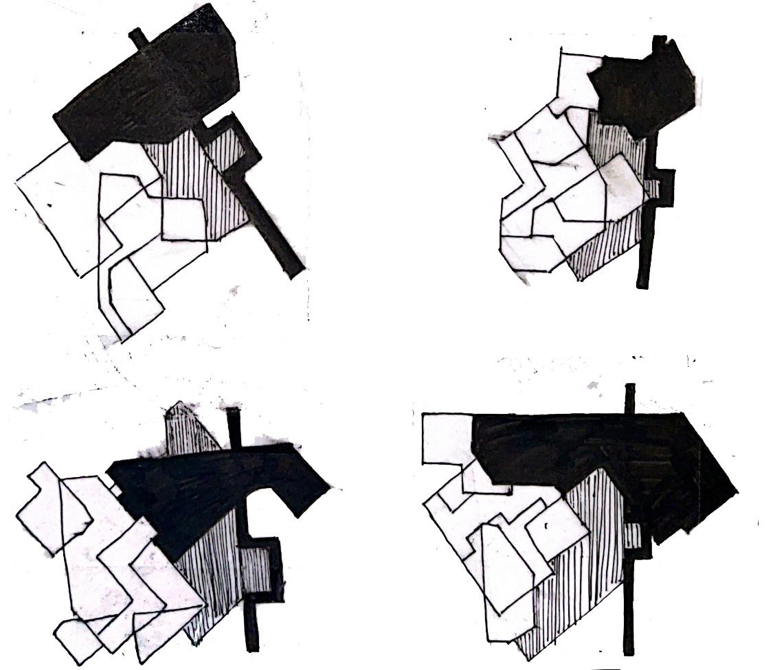
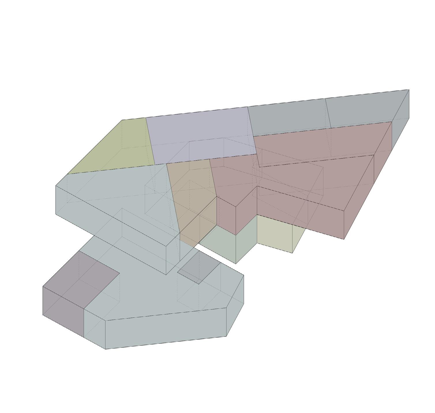
DEVELOPMENT CONCEPT
Site Boundaries
Concept:
Shapes from line connections
Combined grids and new-formed shapes
Bottom Layer
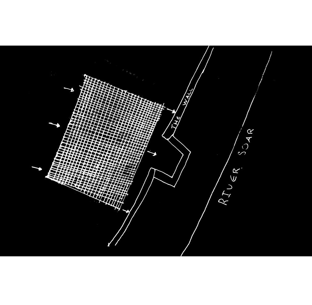
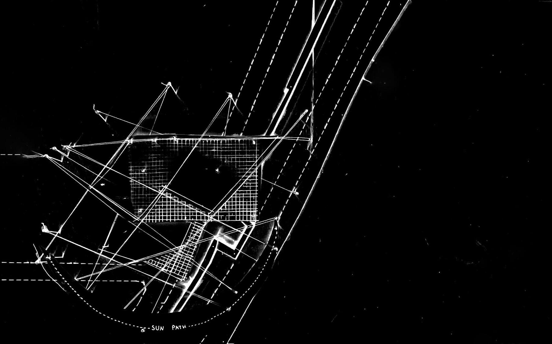
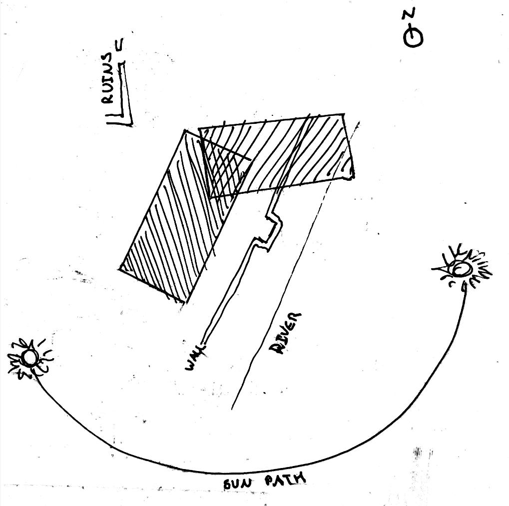
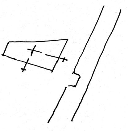
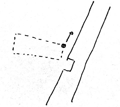
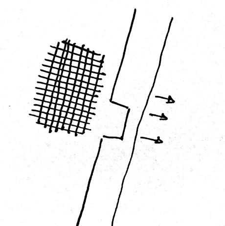
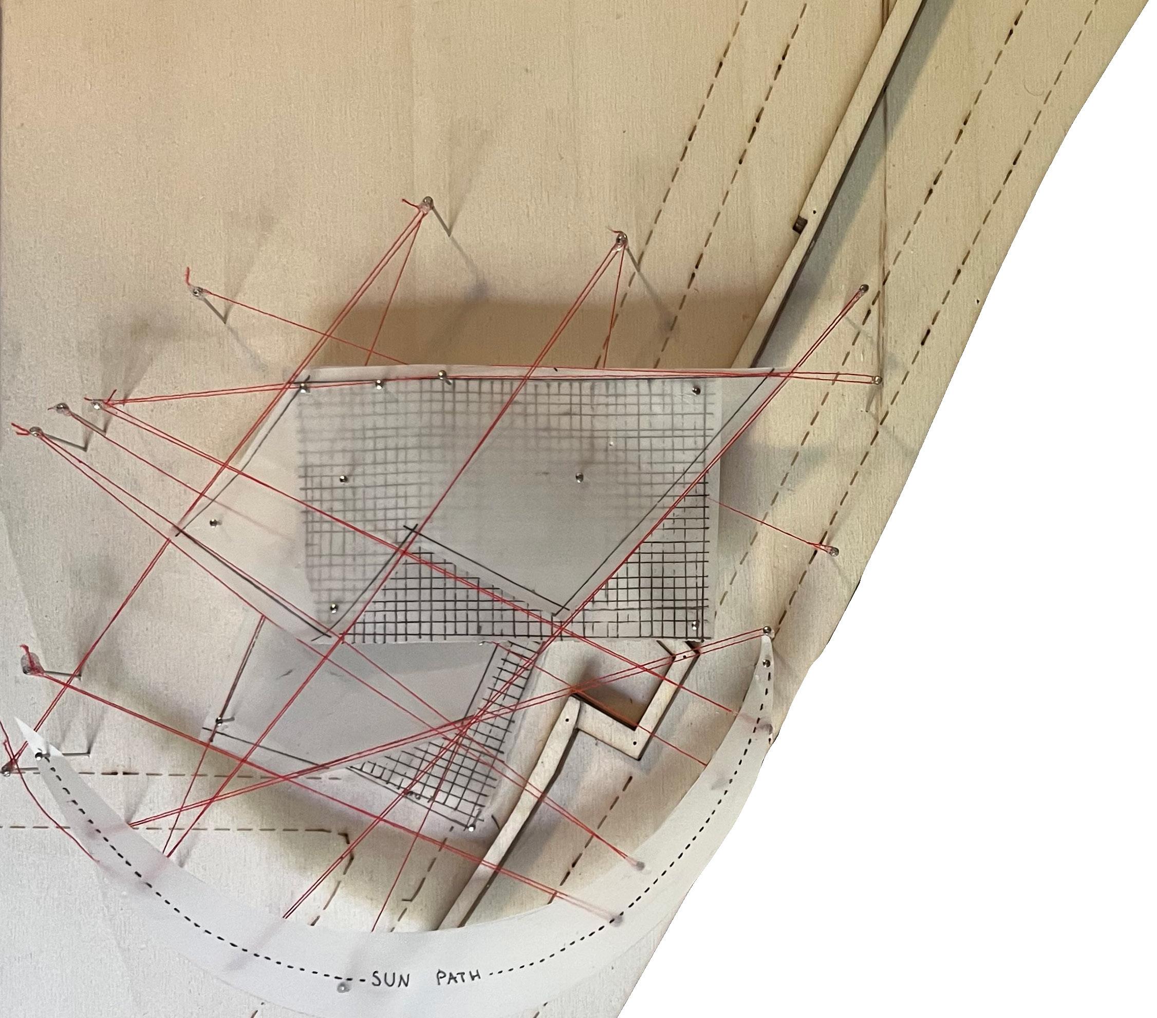
This concept diagram follows from the site and its different features by placing connection points along the wall, its perforation, the river and the runis. These connection points are then interconnected in a network of lines - some of which run parallel and others cross-over.
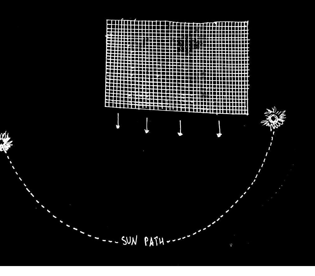
Two overlapping rectangular grids are also placed into this sequence where the layer below runs parallel to the wall and river at its length, whereas the upper grid is directed to the sun path at its length.
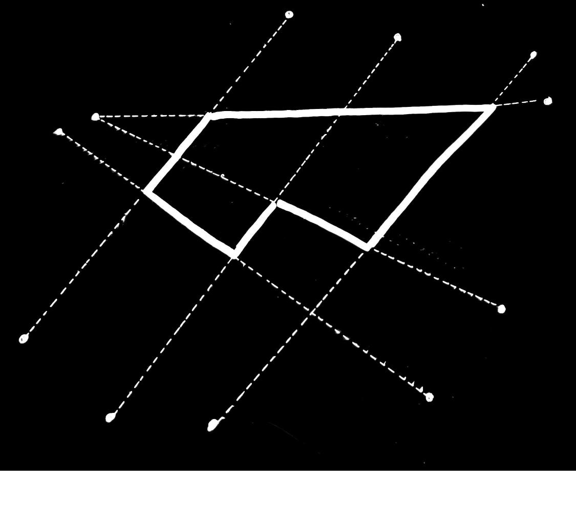

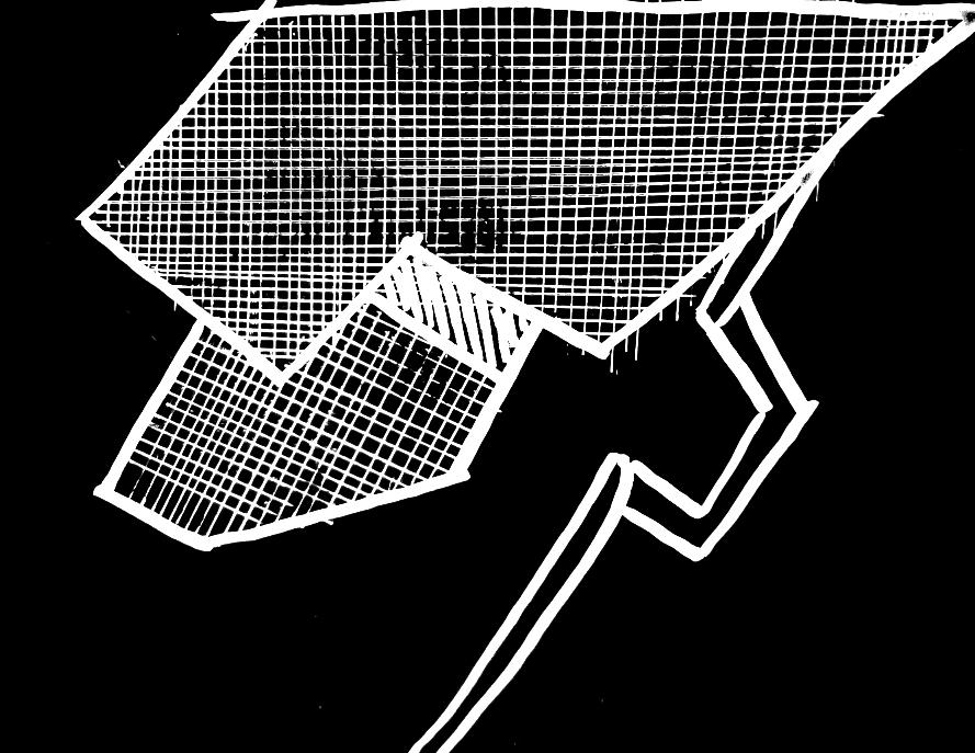
The combination of the linear network and the overlaping grids creates shapes on the sites plane and intersections to the grids.
 Top Grid
Bottom Grid
2) 3) 4)
Top Layer
Top Grid
Bottom Grid
2) 3) 4)
Top Layer
14 15
DEVELOPMENT CONCEPT
MODEL
Final Concept Model Development:
Refinement:
- 30-60-90 square grid
- Maintaining 45-135 degrees at angles/ edges of structure
This grid allows the angles to correspond to one another, helping to refine and control the overall geometry of the structure, as well as making it easier to furnish the interior spaces.
Combined
Grid Follows Wall & River Extrapulation in relation to site Separation of Public and Private spaces
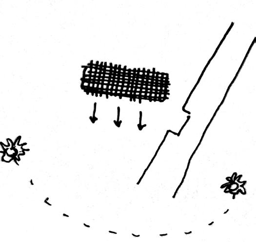
Grid Follows sun path Extrapulation in relation to site
Iteration increasing SA exposed to sun path
Ground
First Floor
(In
Final Plan Outline
Application of calculated underlying grids:
Floor
(In blue)
red)
Concept 16 17
ground and first floor volumes
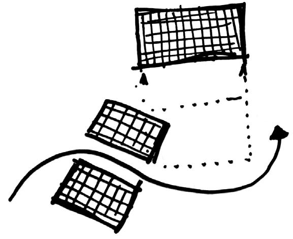
DEVELOPMENT CORE
DESIGN


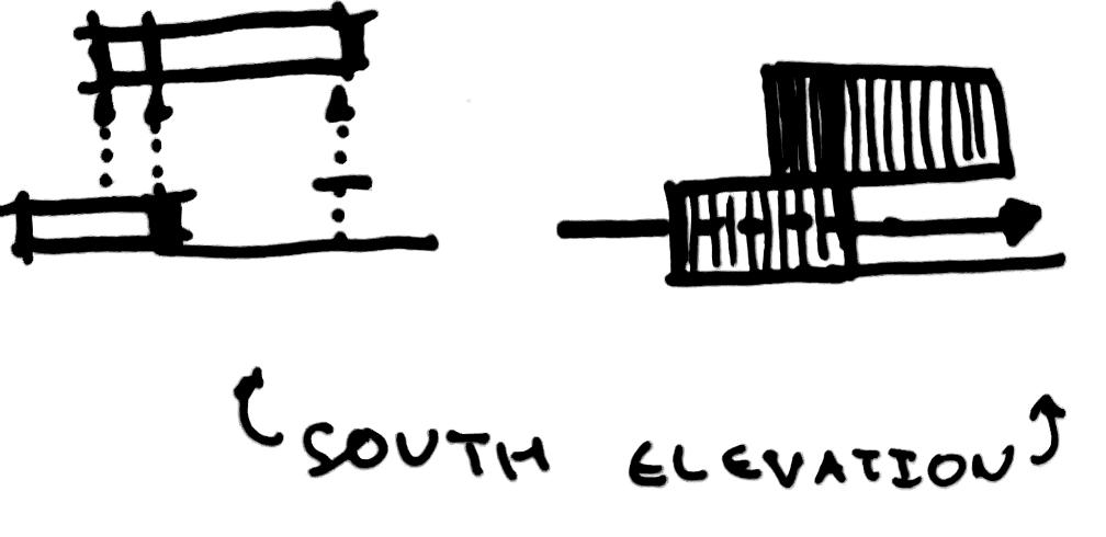
Parti Diagrams:


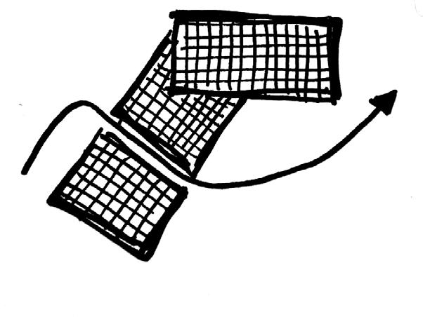
To start with the development of my core design, chose to simply outline my ‘over-lapping grid’ concept and illustrate how it has influenced the plans and form of my structure through simple drawn plan and elevation views.
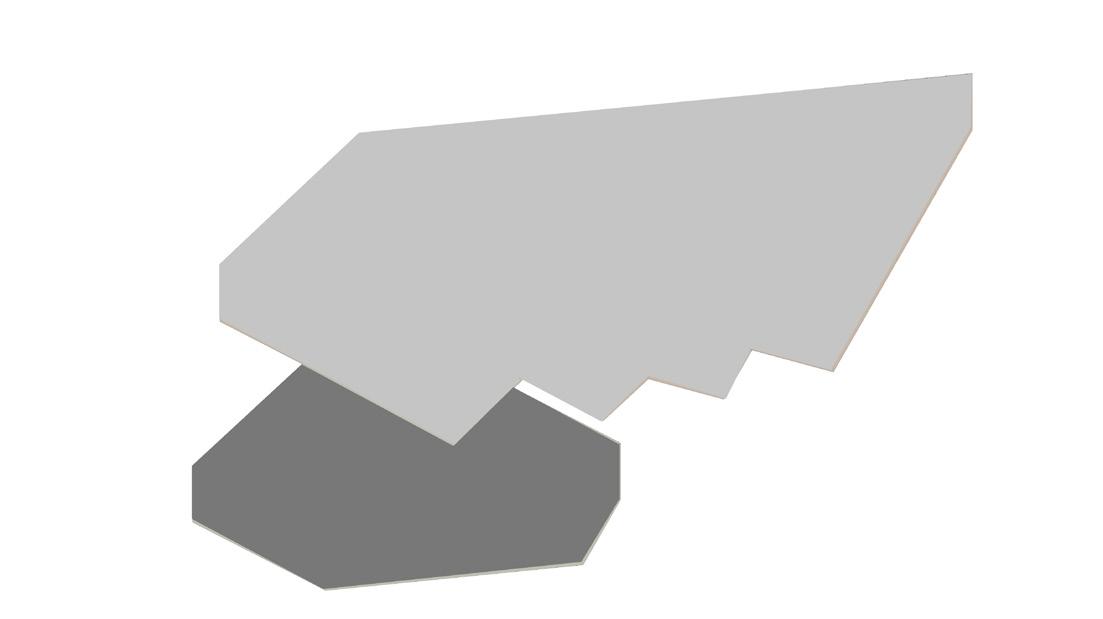
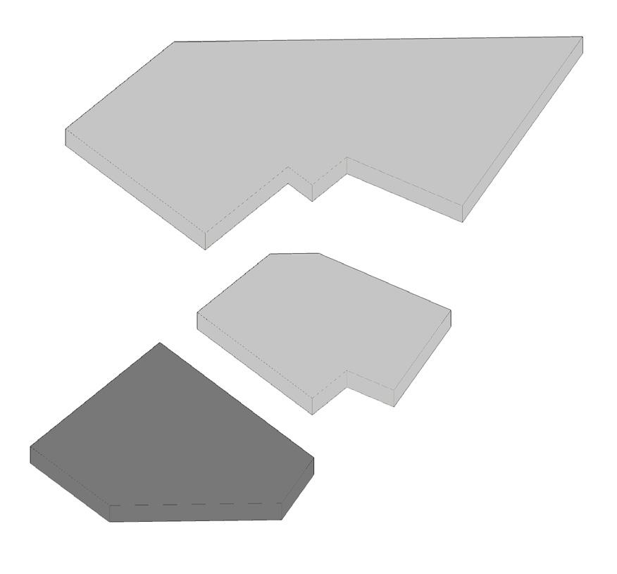

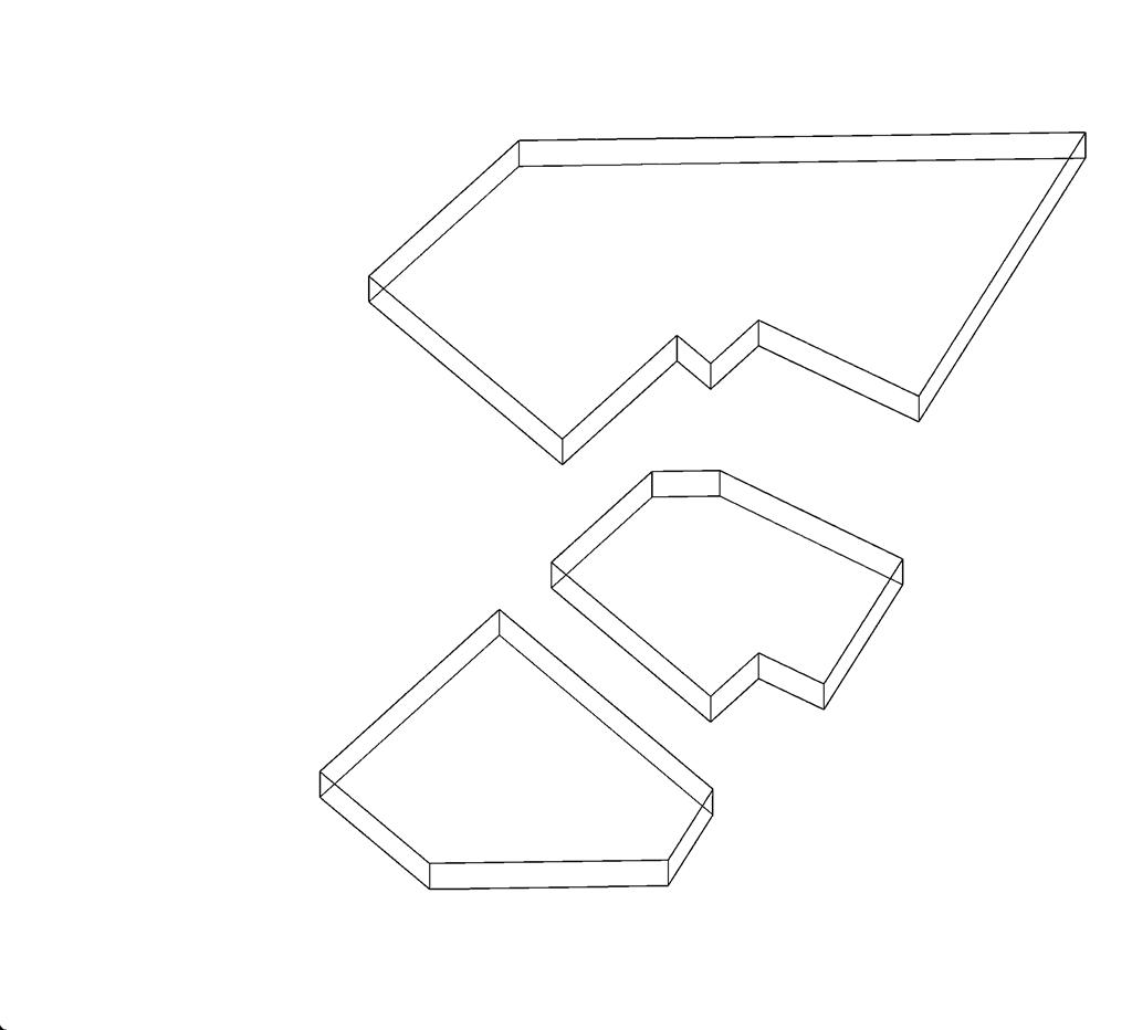
These diagrams show the three main volumes of structure, how they stand in relation to one another, separation of public and private as well as the creation of more circulation.
Architectural Programme: Bubble Diagrams:
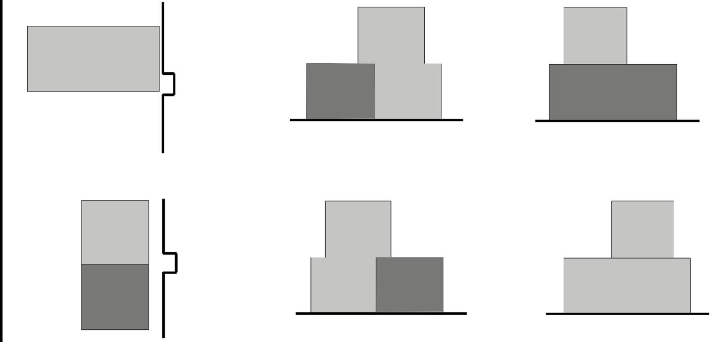
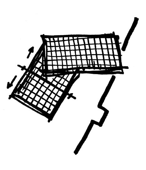
Public vs Private:
The main problem of my site that is to be addressed in this design is the risk of invasion of privacy from the parks visitors. A simple solution for this was to split the ground floor into two sections, where the private living spaces of the house are located in the north section of the site, whereas the public gallery space is located to the south, towards the public cafe and the rest of the main visitor sections of the park.
Circulation:
The circulation around the house is almost directly influenced by the site and its already established pathways (running along the wall and the ruins). Towards the south of the the building is both public and private access, wereas from the north it is strictly private circulation.
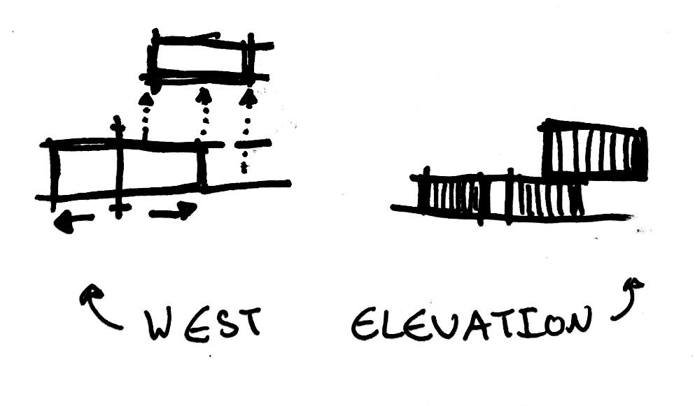
Public
An important thing to note here is that the structural separation at the ground floor of the house still has staircase access through to the rest of the house through the first floor.
Workspace/Studio Living Dining Kitchen Bathroom Bedrooms Study/ Guest Room Storage Wardrobe Wall Entry Toilet Garden Services River Key Public Private
Floor Plan West Elevation South Elevation Entry 4m2 Living 15m2 Toilet 2m2 6m2 Kitchen 6m2 Dining Services Storage 3m2 Circulation 6m2 Bathroom 12m2 Bedroom 50m2 Workplace/ Studio
Floor Plan East Elevation
Elevation
Ground
First
North
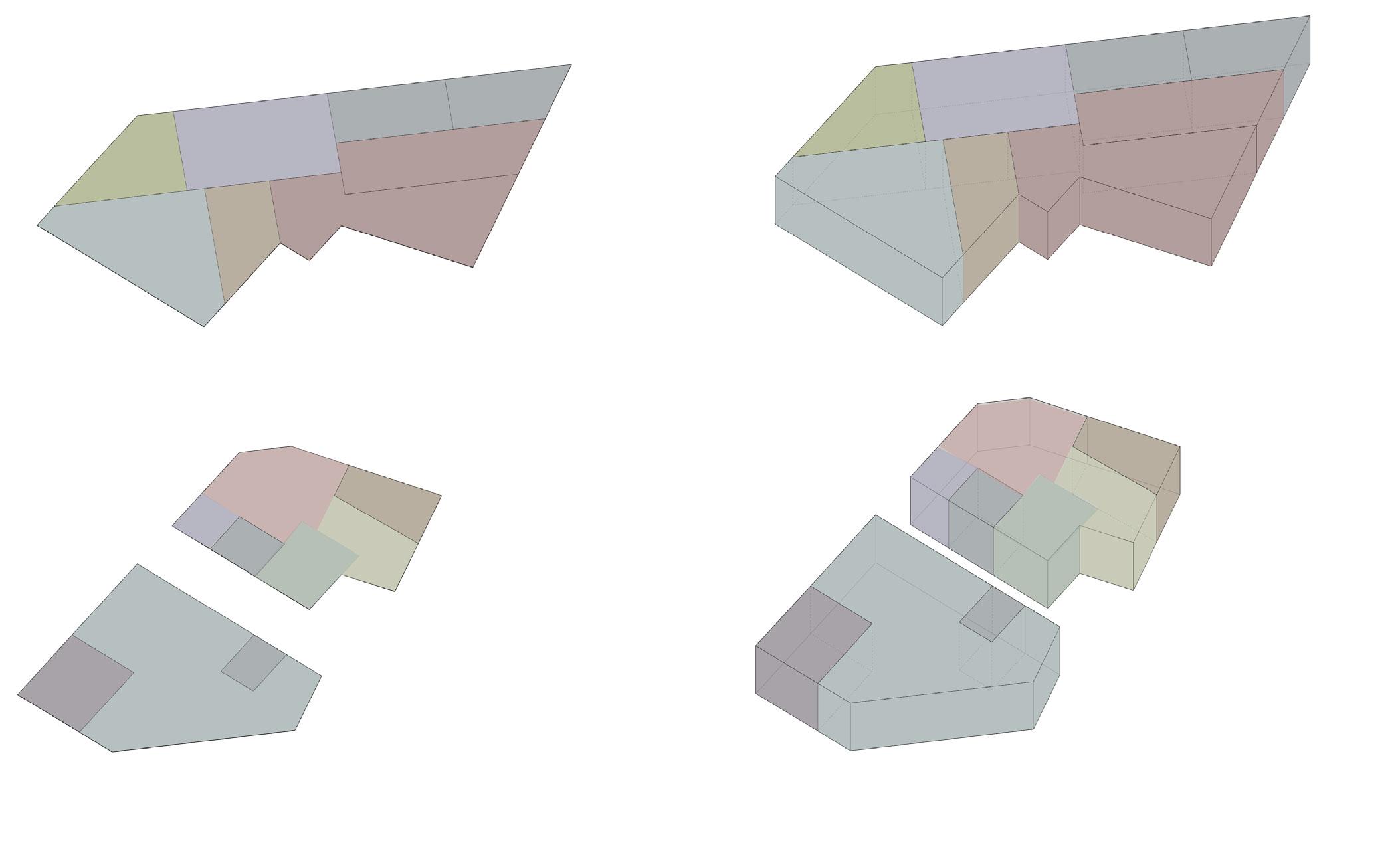
Key Plan Views Separating the Layers Elevation Views
Circulation
Building Circulation inside building Minimum Area Requirement of Spaces
relation to
Spaces in Relation to Each Other and in Context of Site Bathroom Bedroom Key Study/ Guestroom Storage Living Kitchen Studio/ Workspace VR Dining Flat Plans Aligned Added Height to Plans Ground Floor & First Floor Volumes Together
Plans and Elevations of Public & Private Spaces Separation of Public from Private Circulation of Public (visitors) and Private(Residents) Outdoor
around
(in
each other):
Extra
Private Key Public Private 18 19
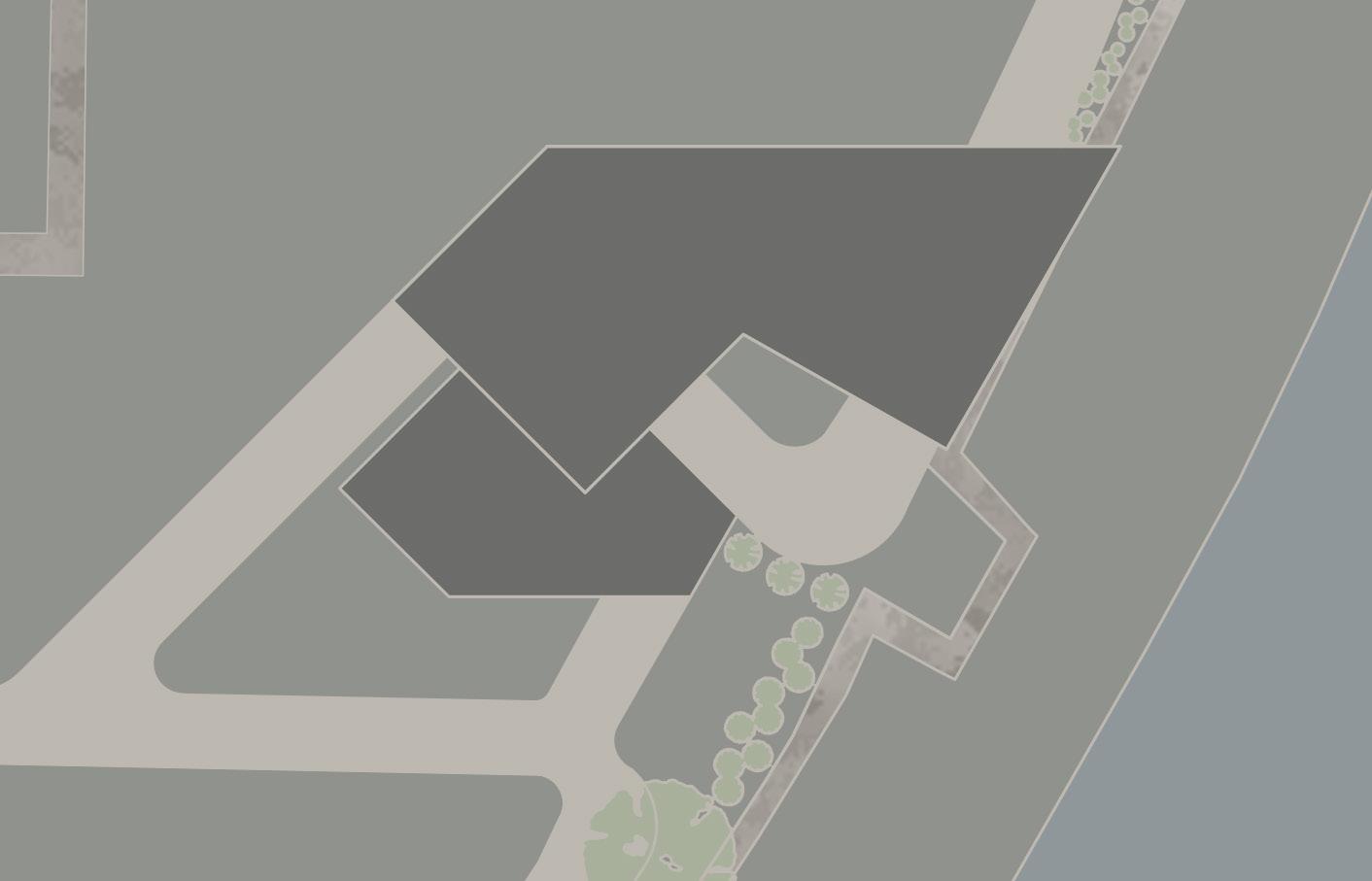
FINAL DESIGN REVIEW
(Not to Scale)
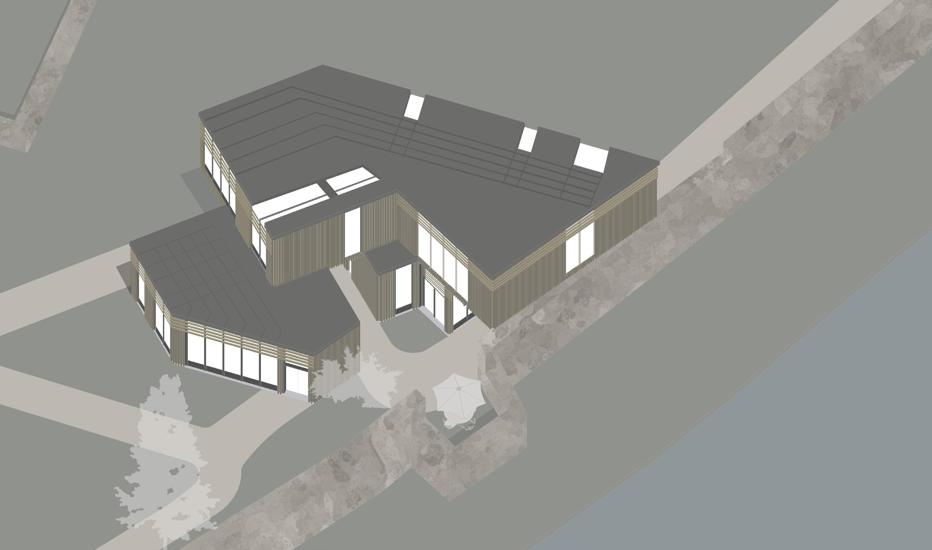
Narrative:
The concept for this house design follows from the use of layered grids and connecrtions from the site, all of which considers the relationship with the neighbouring wall and the sun path. The outcome of my design process is a two storey house which consists of its main living spaces to the north at the ground floor of the building as well as the first floor. Whereas the public space of the gallery is located only on the ground floor at the south of the building, where it is directed towards the cafe and main public spaces of the park in order to attract visitors.
The problems I was faced with at the begining of this project was the risk of lack of privacy due to requiring a gallery space for my client as well as working with the existing wall withought directily interacting with it. The first issue was solved by splitting the ground floor into two sections, where to the south consists of the public spaces such as the gallery and to the north is the living spaces. As a result of this designm neither of the spaces directly interact with each other, as the gallery space can only be reached through either the studio/ workspace of the house or through outdoor entrances located to the south of the house. The second issue of the wall was overcome by having the building not come in direct contact with the wall. In this design the first floor is still able to overlap the wall through cantilever, providing views of the river and rest of the park.
1:200 2m 12m 20m
20 21
FINAL DESIGN PLANS 1:100
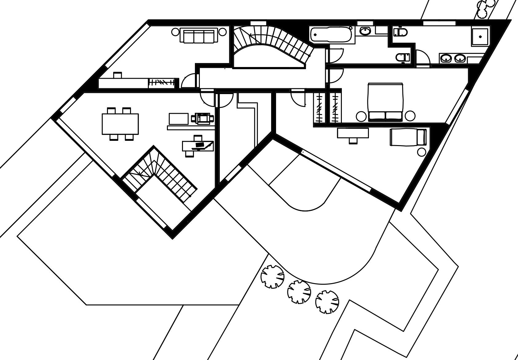
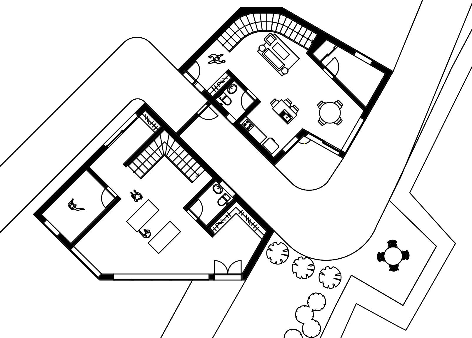
Ground Floor 1:100 2m 7m 10m 52.23m2 7.19m2 2.96m2 35.39m2 4.97m2 2.18m2 First Floor 26.3m2 14.86m2 5.83m2 1:100 2m 7m 10m Roof 1:100 2m 7m 10m 7.82m2 20.9m2 18.05m2 6.71m2 7.24m2
4 6 8 10 12 14 16 18 20 m 22 23
FINAL DESIGN
ELEVATIONS 1:100
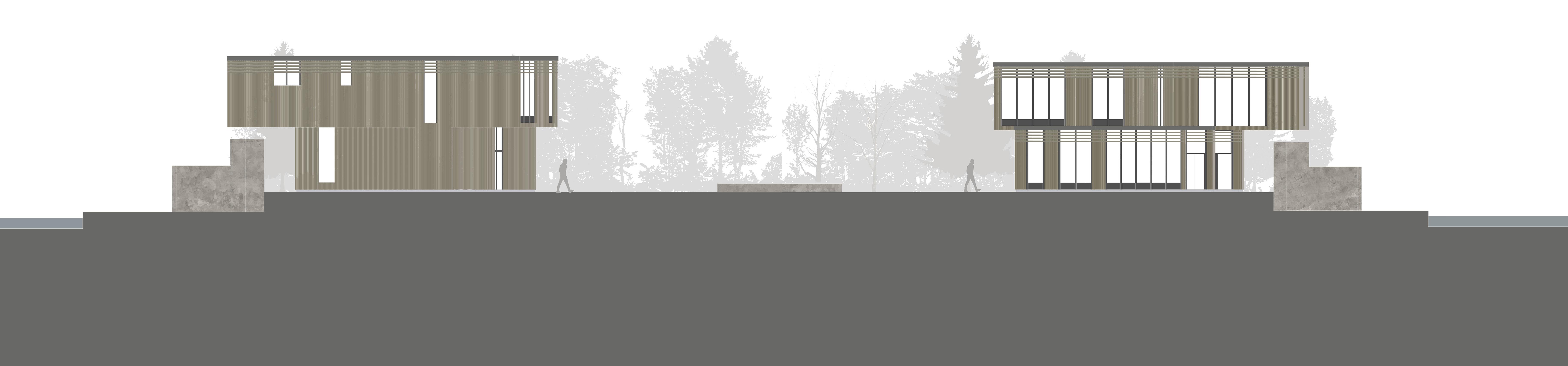
North- West Elevation 1:100 1m 6m 10m South- West Elevation 1:100 1m 6m 10m
24 25
FINAL DESIGN
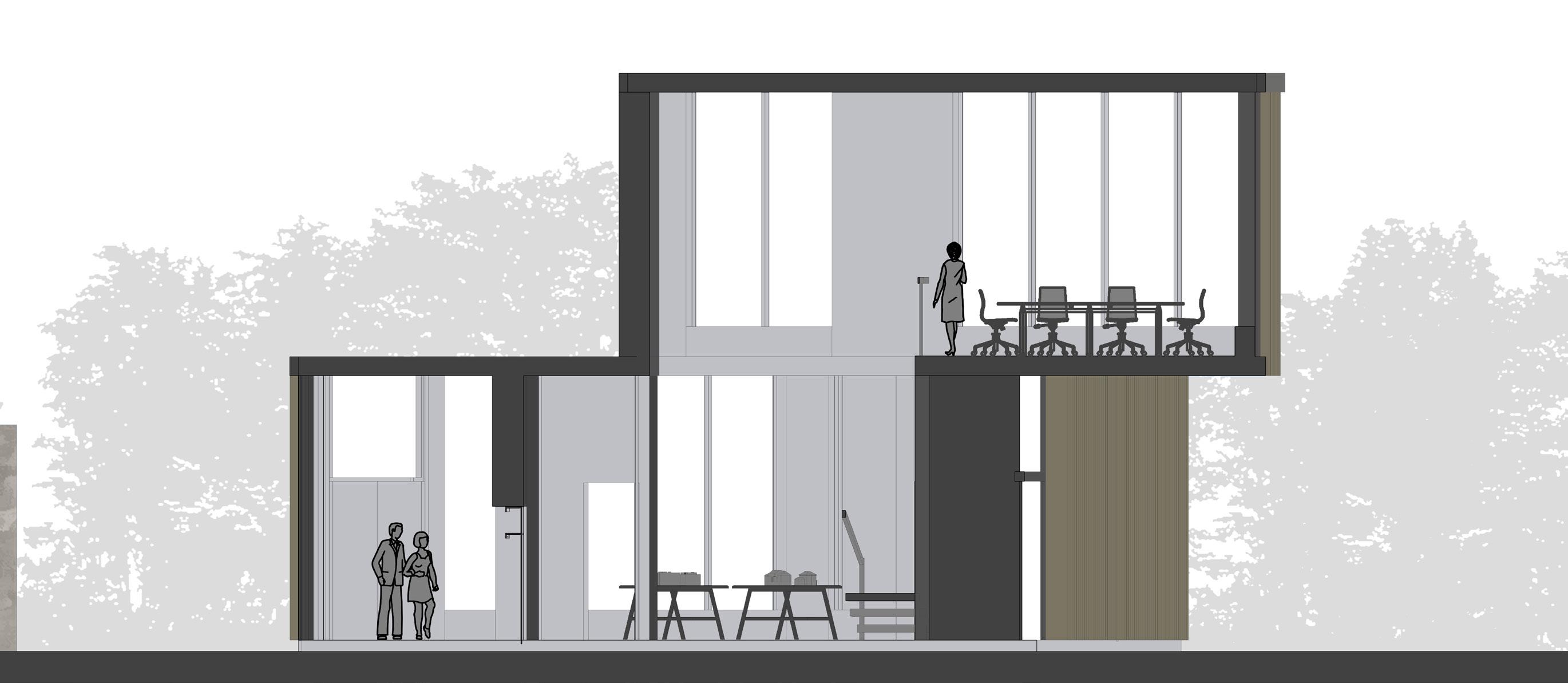
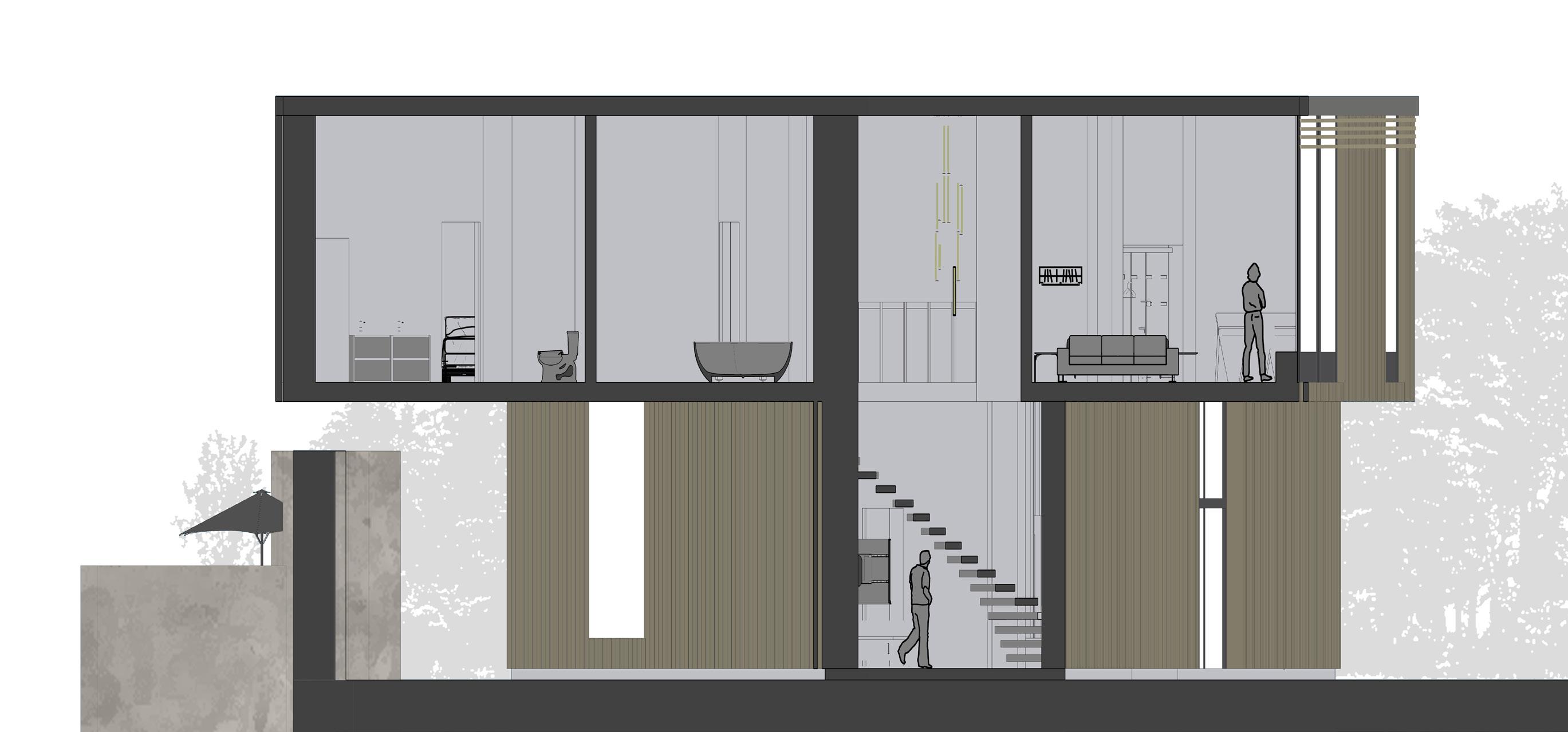
SECTIONS 1:100
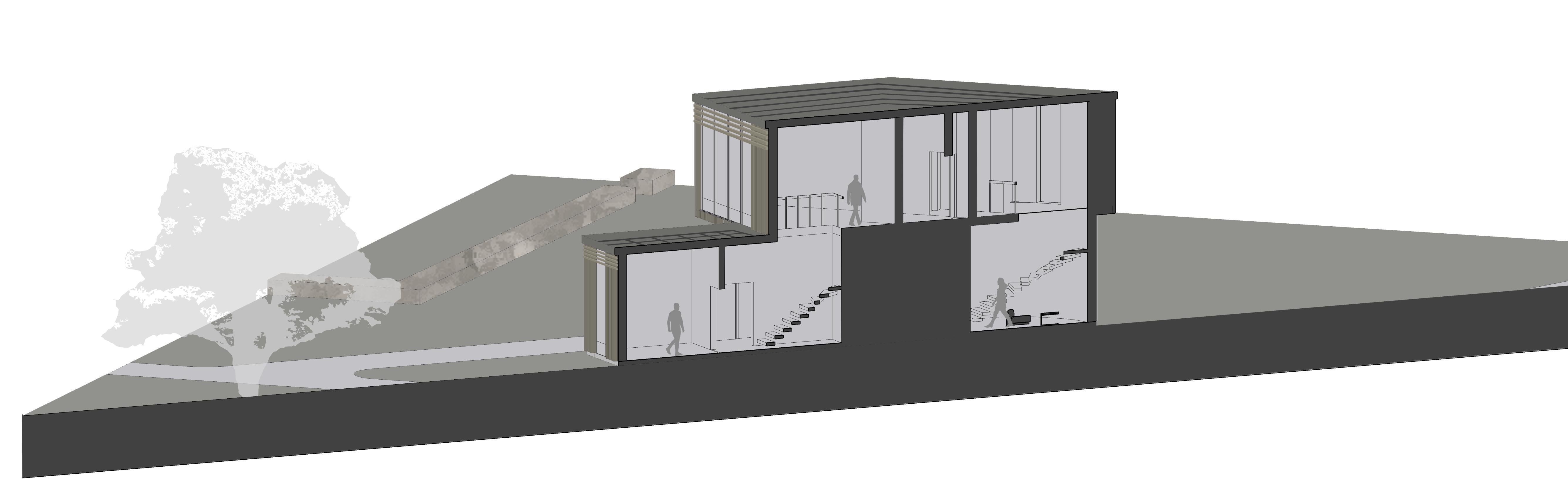
1:100 1m 6m 10m Section A Section A 3m 2.6m 3.5m 3.5m 3.5m Section B 1:100 1m 6m 10m 3.5m 3.5m Section B
Private Living Spaces of House Gallery and Studio/ Workplace
26 27
(Not to Scale)
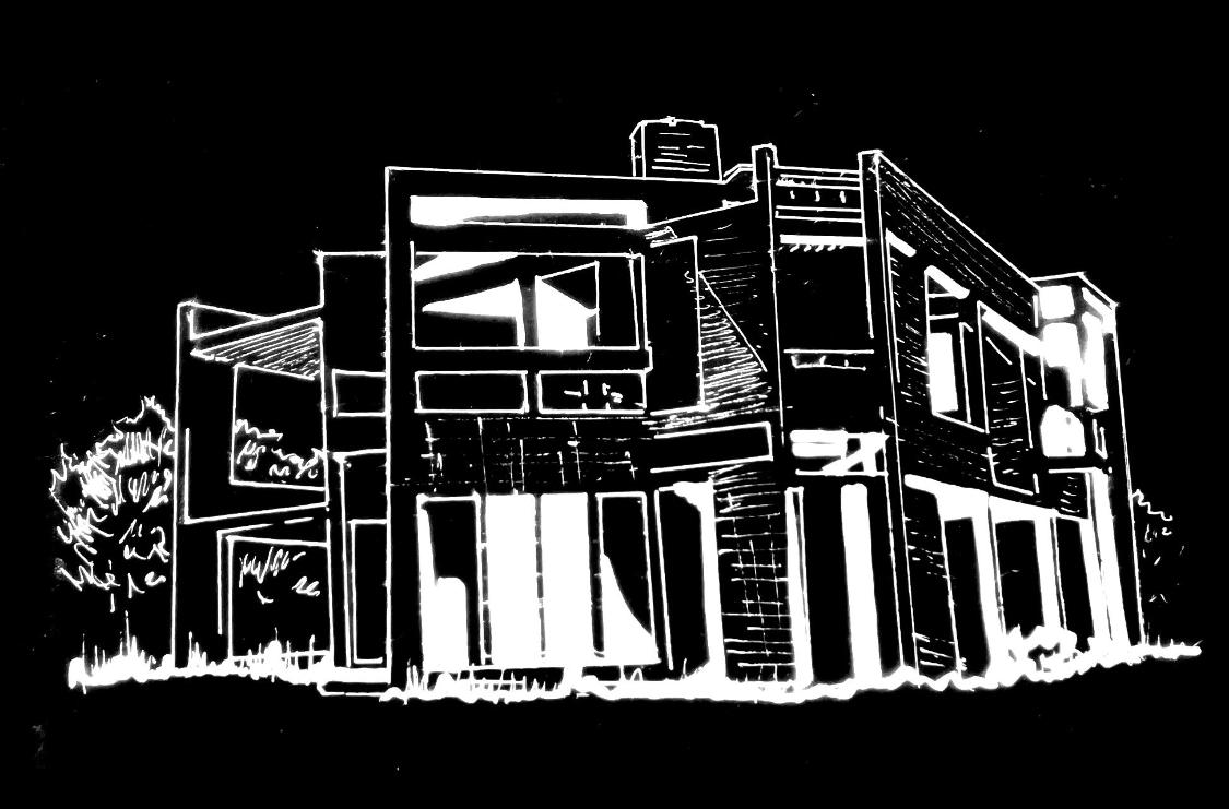
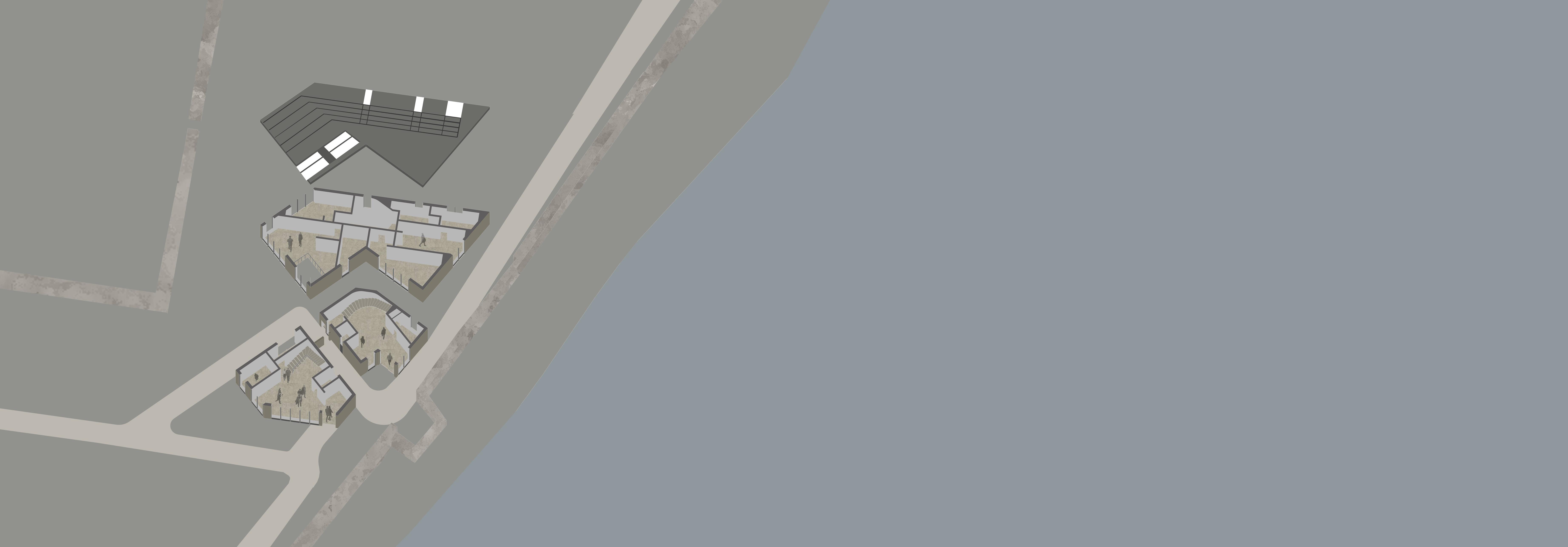
FINAL DESIGN ISONOMETRIC
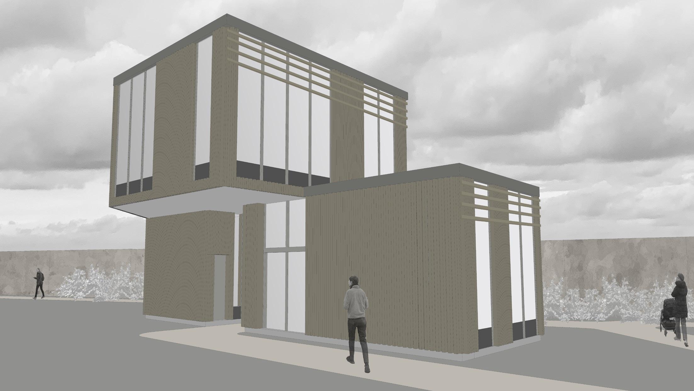
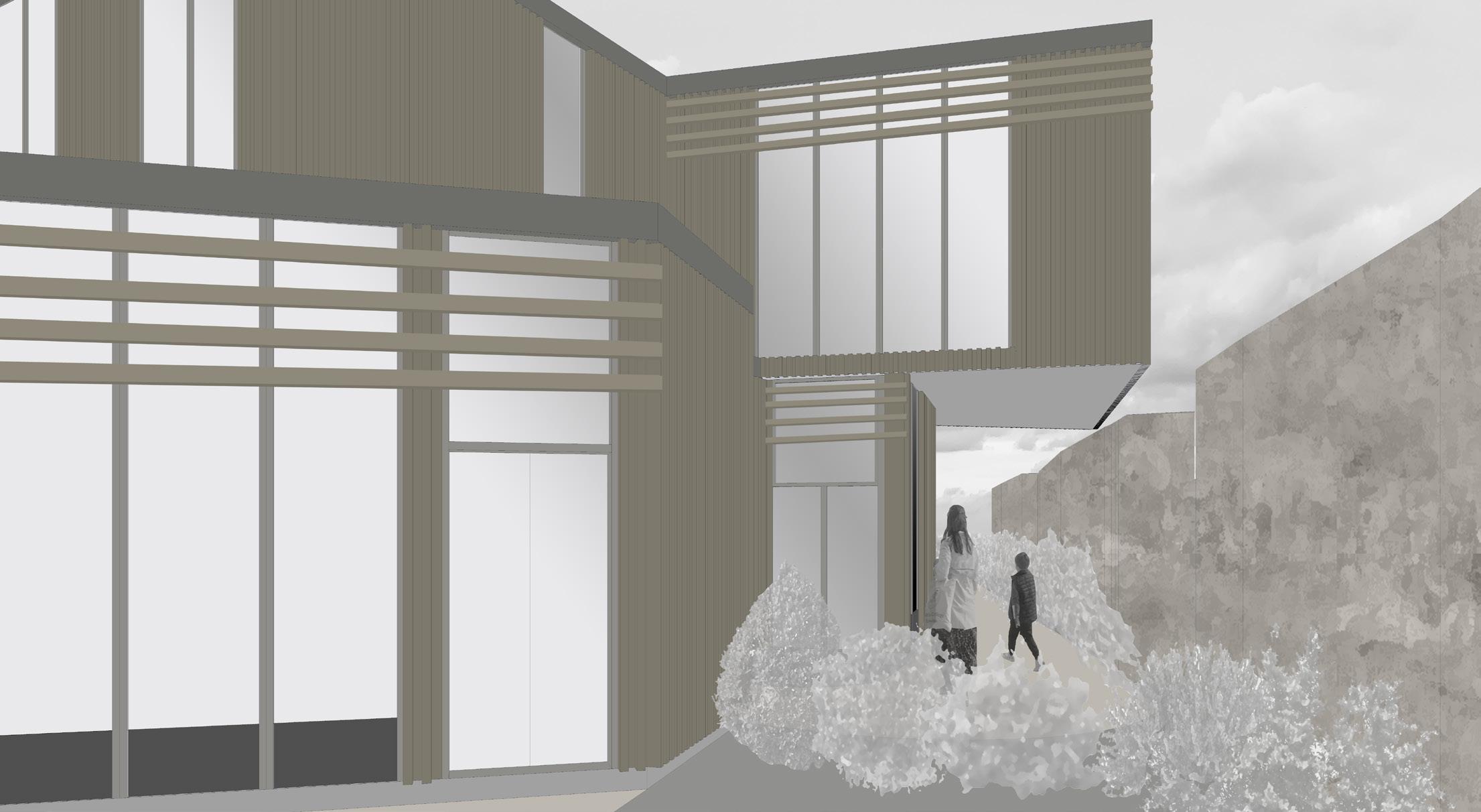
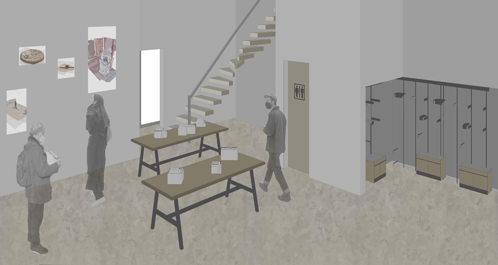
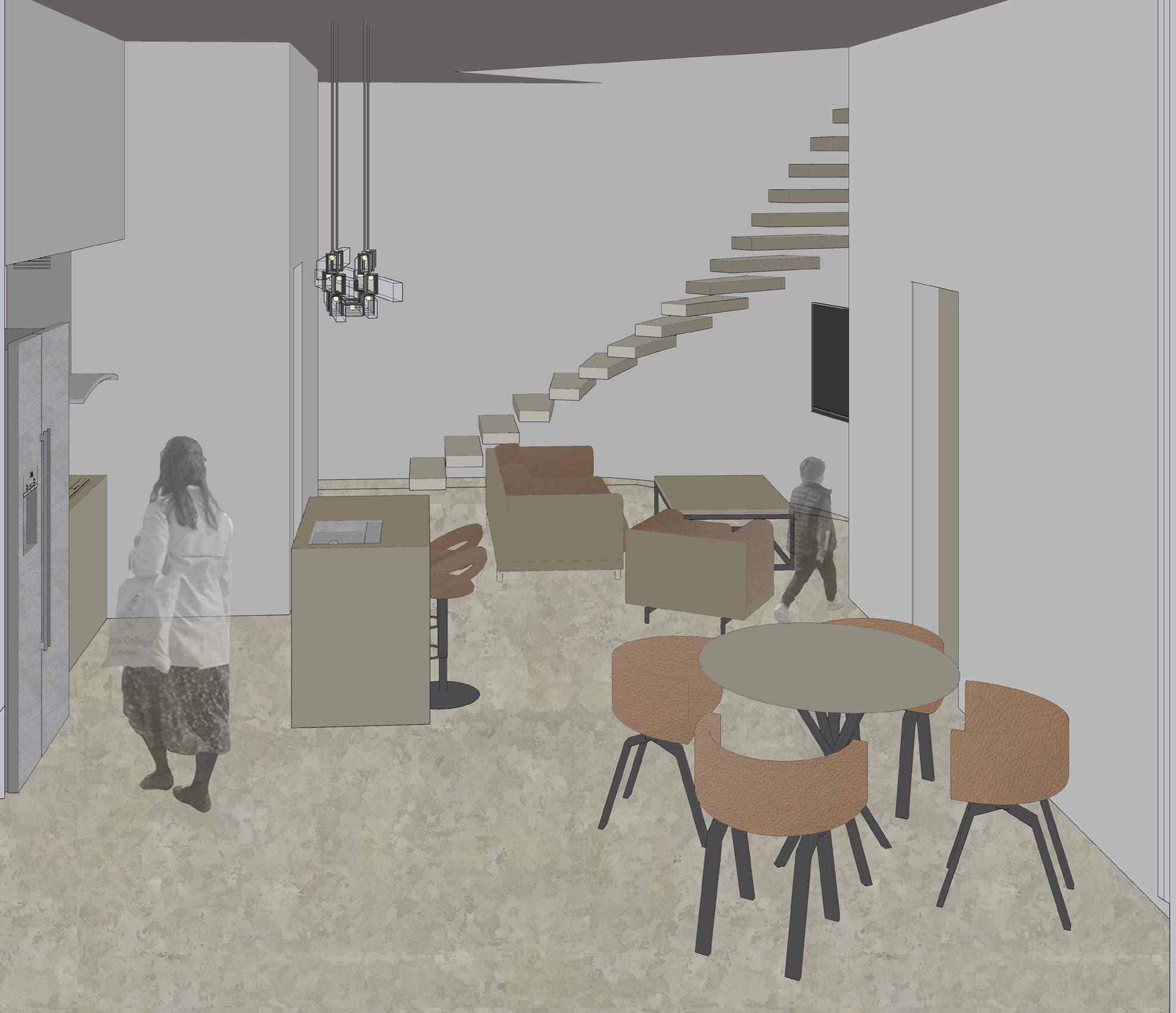
INTERIOR PERSPECTIVES EXTERIOR PERSPECTIVES
Living Space Interior Exhibition/Gallery Space Interior
28 29 (Not to Scale)
Exterior Perspective of House Entrance Exterior Perspective of Gallery Entrance and Garden Gallery VR Room Living Space Storage Room Public Toilet Toilet Studio/ Workspace Study/ Guest Room Corridoor Bathroom Ensuite Master Bedroom Bedroom Storage Room
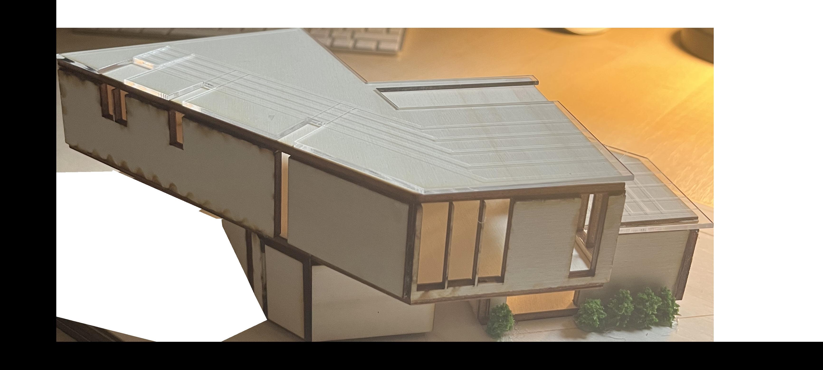
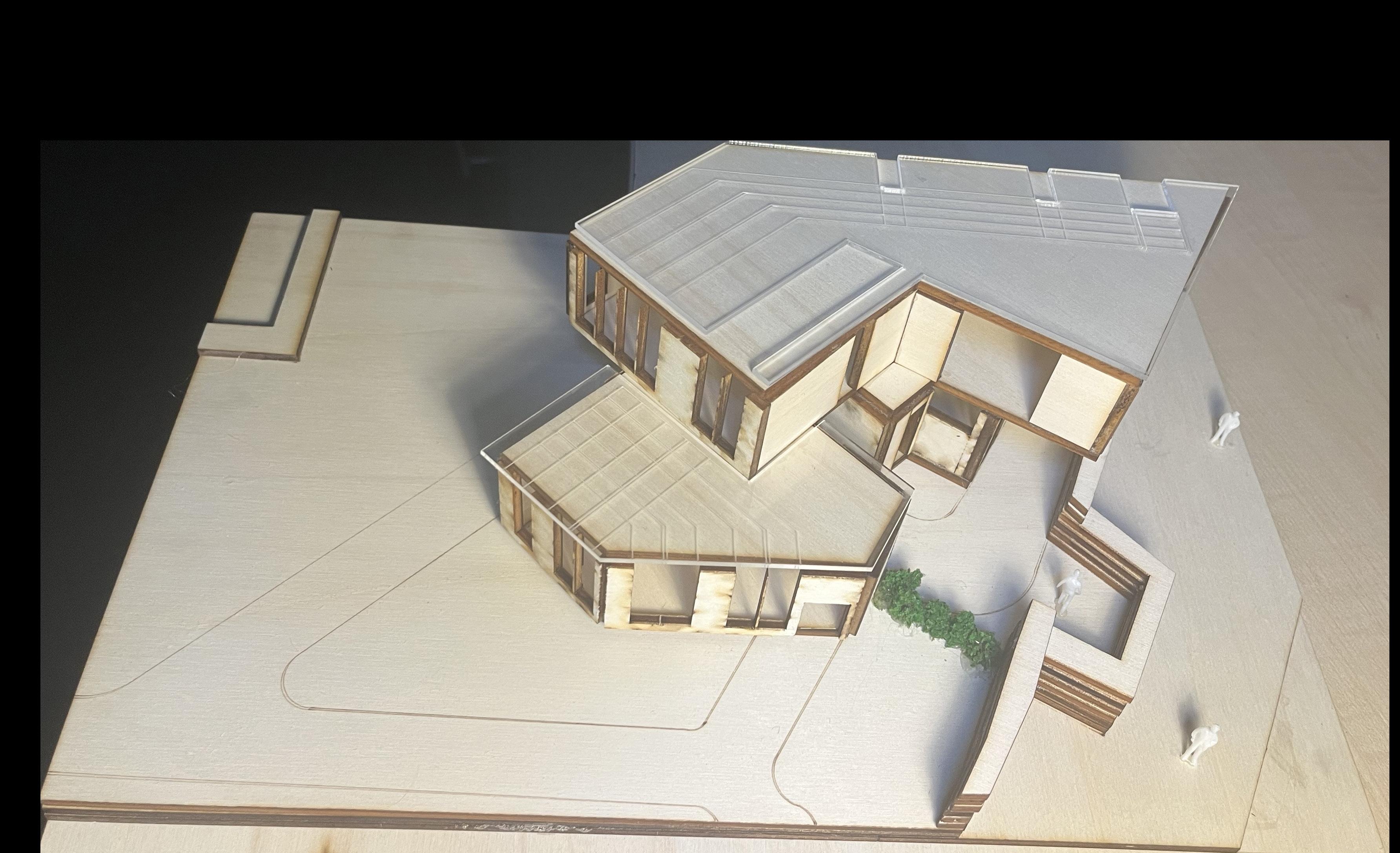
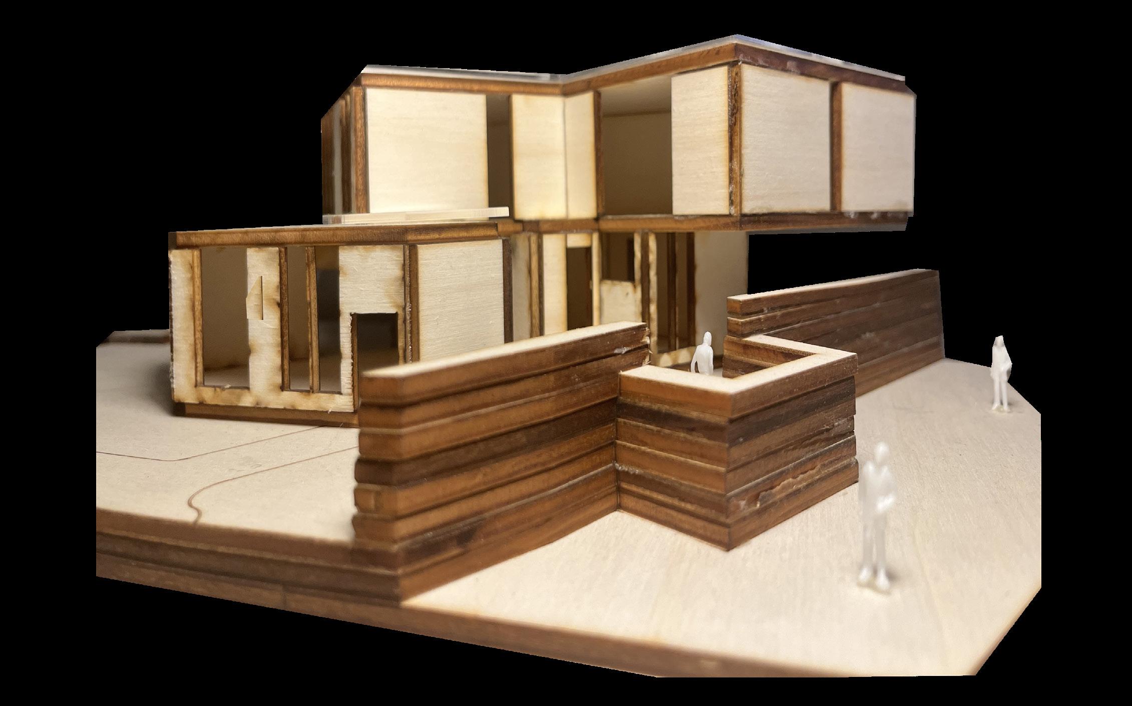
PHYSICAL MODEL
FINAL DESIGN PAVILION
South- East Perspective
In the final stage of my project created a physical model in the scale of 1:100 from plywood and acrylic so that I could better assess the volumetrics of my design and how it interacts with the existing site. By creating a model it also allowed be to better understand the construction and structural quality of the building design.
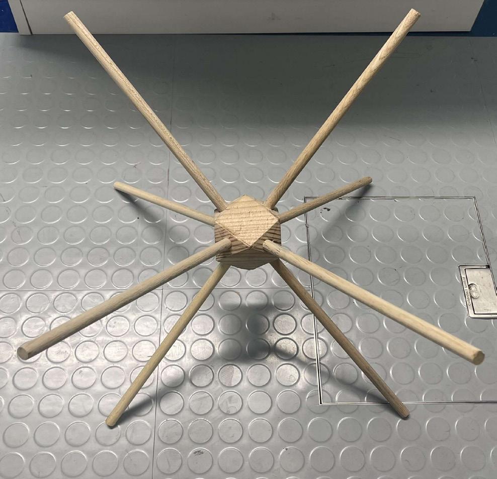
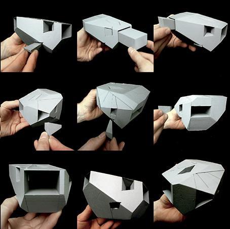
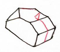
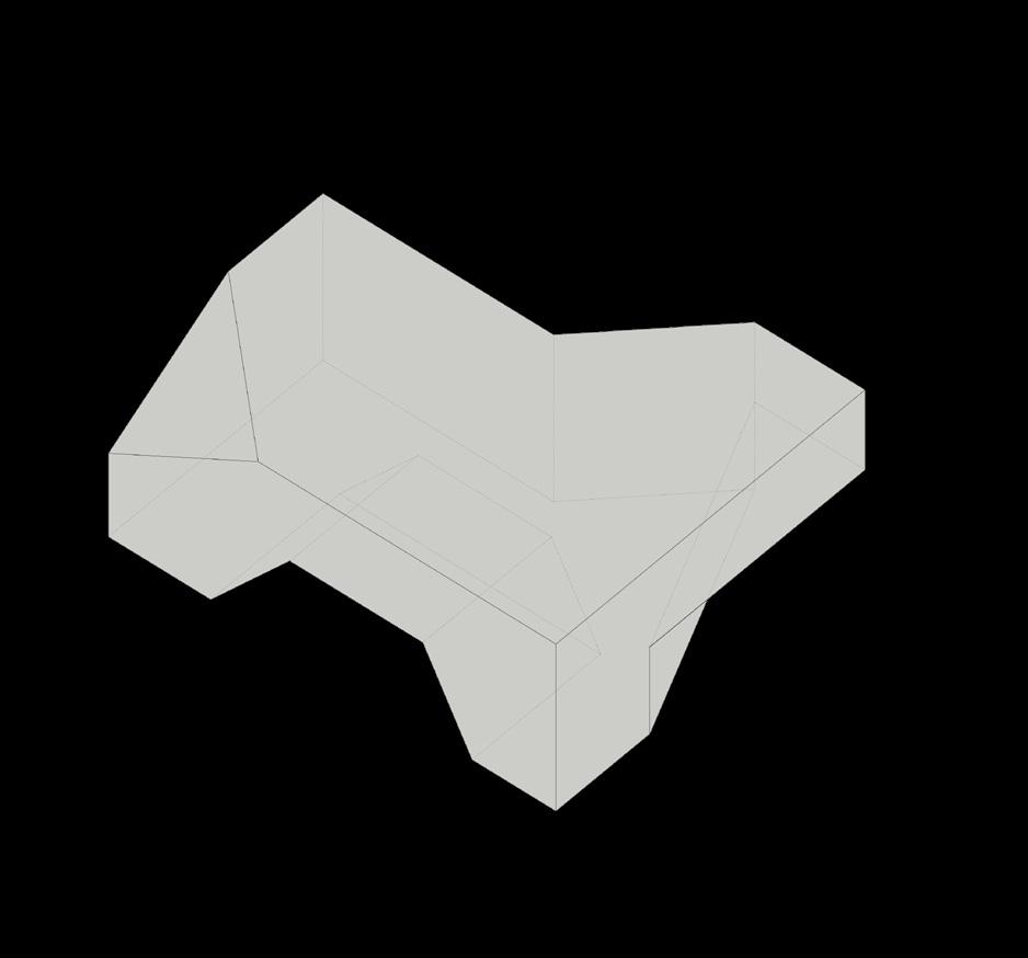
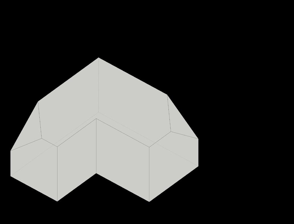
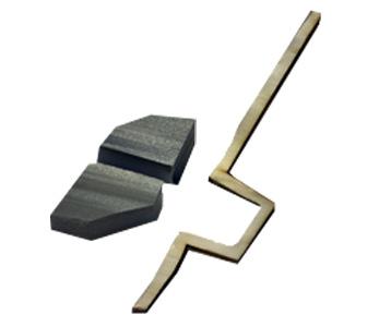
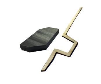
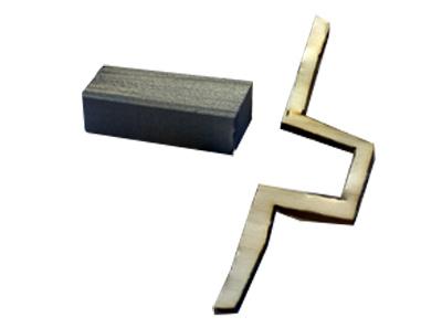
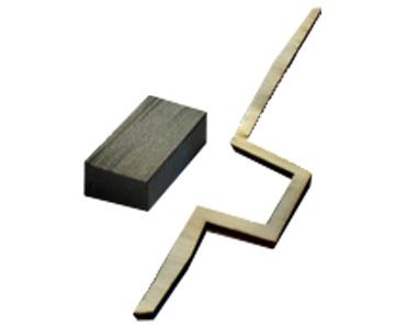
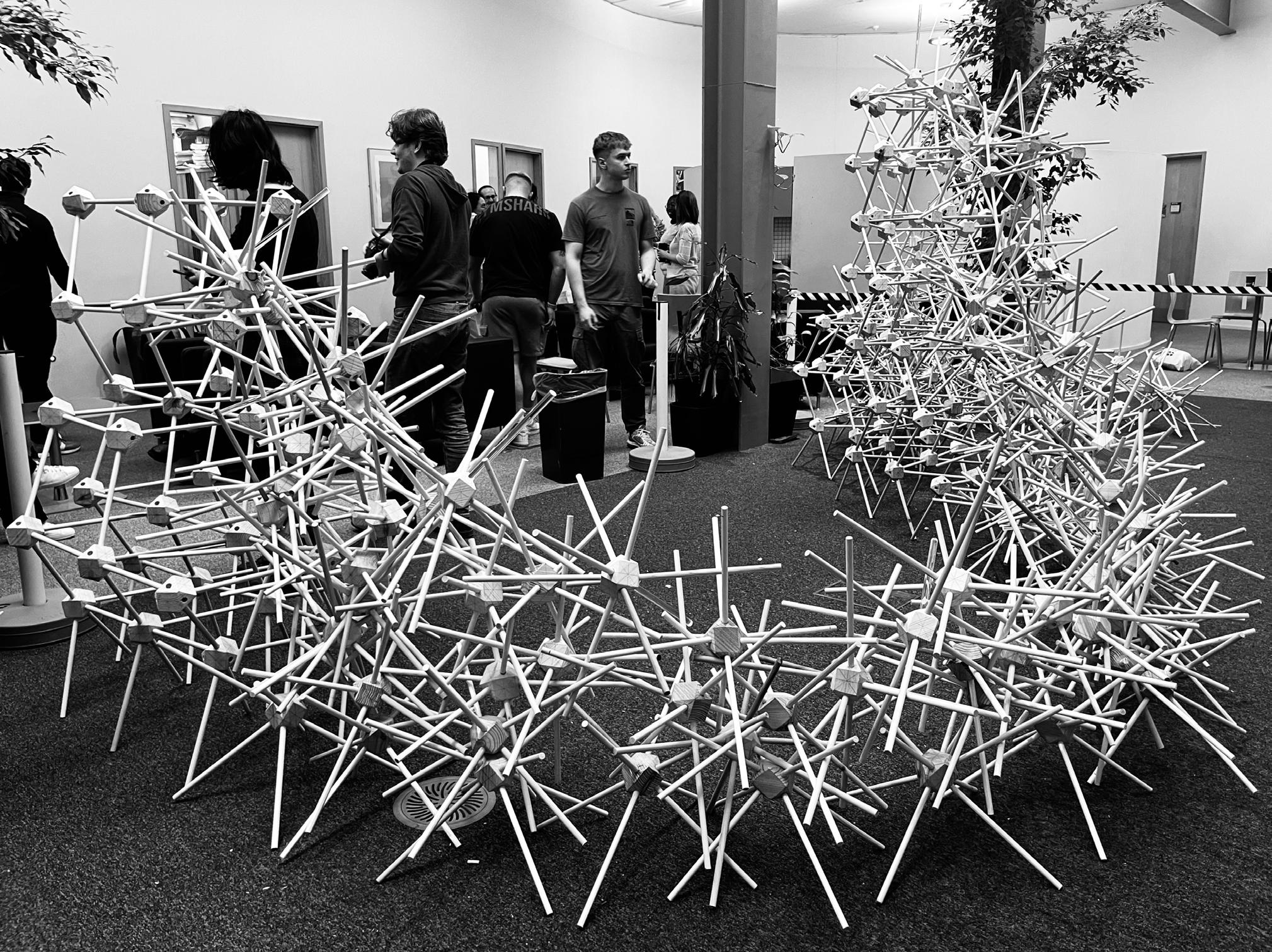
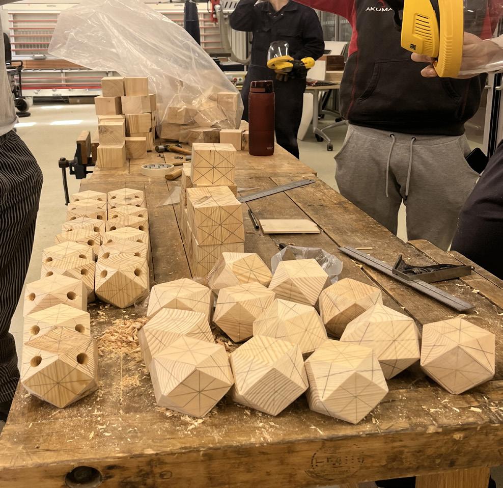
Final Pavilion Construction
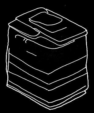
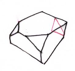
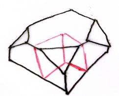
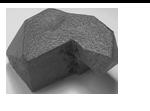
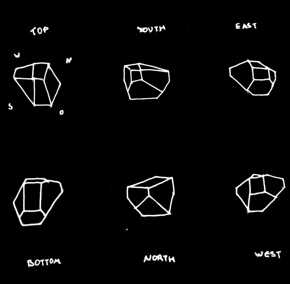
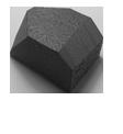
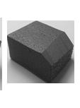
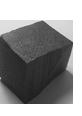
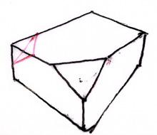
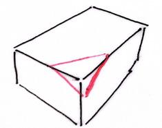
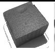
My participation in the pavilion project was primarily focused on the manufacturing of elements in the Frank Gibb lab. This task consisted of meansuring and marking out the desired shape on the faces of a cube. The second stage of this process required the 4 edges of the cube to be filed down to the marked lines to achieve this 14-faced faceted form. The next stage after this woud be to drill holes into the the centre of the triangular faces of the form.
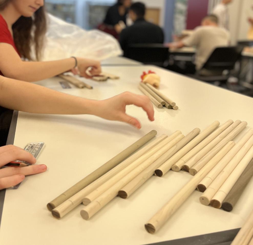
Towards the final stages of the pavilion construction, I also participated in the measuring of the elements wooden poleswhich had to be marked 2 cm from its edges so these poles could then be inserted into each of the 4 drilled holes of the elements core.
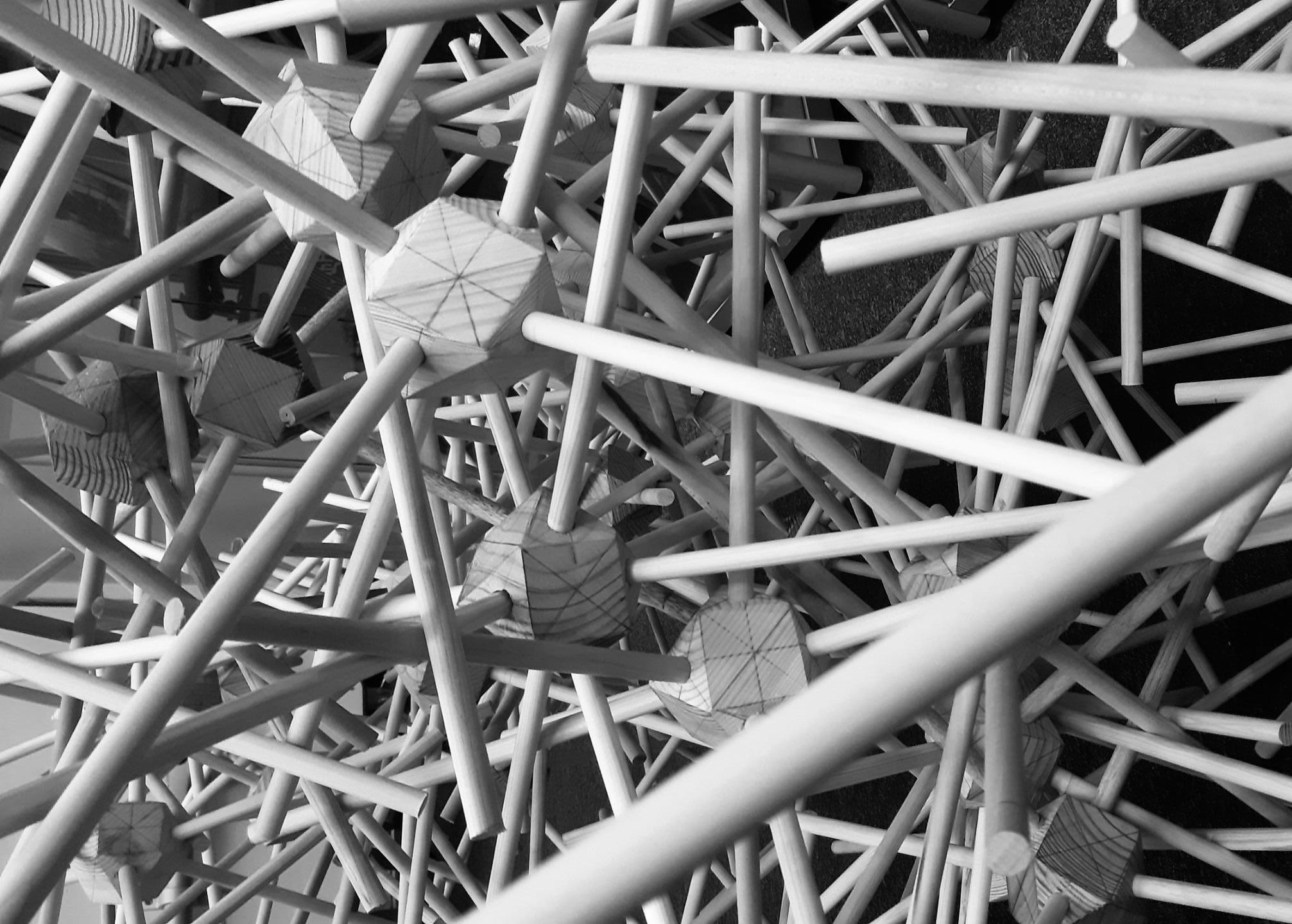
Lastly, on the day of the construction of the pavilion, I participated by assembling the elements using the core and their corresponding poles. Once these were assembled, it could them be placed into the sequence of elements which constructed the pavilion.
North- West Perspective
Manufacturing Measuring Assembling
30 31
REFERENCE LIST
Aber, JS et al (1010). ‘Small Format Aerial Photography’, Science Direct, pp1-13. Available at: https://www.sciencedirect.com/topics/agricultural-and-biological-sciences/photogrammetry#:~:text=Photogrammetry%20is%20the%20 art%2C%20science (Accessed: 15 May 2022)
(Figure 1) Menlioglu, Hilal. (n.d.) “Hilal Menlioglu - DUT: Digitalized Urban Tales”. Available at: Menlioglu.myportfolio.com, menlioglu.myportfolio.com/digitalized-urban-tales-dut (Accessed 15 May 2022)
Figure 2) Balabanian, Azad. (n.d.) “Photogrammetry.” Available at: Azadux, azadux.com/photogrammetry. (Accessed 15 May 2022)
(Figure 3) Adelyn Perez. (2010) “AD Classics: House vi / Peter Eisenman.” Available at: www.archdaily.com/63267/ad-classics-house-vi-peter-eisenman?ad_medium=gallery (Accessed 16 May 2022)
(Figure 4) Eisenman Architects. (n.d.) “House III 1971 — EISENMAN ARCHITECTS.” Available at: Eisenmanarchitects.com, eisenmanarchitects.com/House-III-1971 (Accessed 16 May 2022)
(Figure 5) Ruault, Philippe (2014) “Casa Da Musica / OMA.” Available at: www.archdaily.com/619294/casa-da-musica-oma (Accessed 17 May 2022)
(Figure 6) Viva, Arquitectura. (n.d.) “Casa Da Música, Oporto - OMA - Office for Metropolitan Architecture.” Available at: Arquitectura Viva, arquitecturaviva.com/works/casa-da-musica-10 (Accessed 17 May 2022)
