Water Quality SCM Manual
The City of Johnson City, TN
The City of Kingsport, TN
The City of Bristol, TN
The City of Elizabethton, TN


Northeast TN Water Quality SCM Manual

ERRATA SHEET
This errata list is a list of errors and their corrections that were found after publishing of the September 1, 2024 version of the Northeast Tennessee Water Quality SCM Manual.
Location in Manual
Chapter 3, Table 3.2.2.1, pg 3-2
Chapter 3, Section 3.3.1; pg. 3-16
Chapter 3, Section 3.4.2, pg. 3-23
Chapter 5, Section 5.7, Table 5.7.7.7.1, pg. 5.7-9
Chapter 5, Section 5.12, all pages
Chapter 5, Section 5-15, 1st paragraph and Table 5.15.1.1
Chapter 5, Section 5.16, Table 5.16.6.1, pg.5.16-8
Description of Correction Date
Removed underground detention basin from the list of Group 3 SCMs
Removed underground detention basin from the list of Group 3 SCMs
Removed or edited text to clarify that underground detention basins cannot treat the WQv
Revised text to clarify that MTD underdrain design configurations may differ from what is specified in this section.
Allowed the use of sediment forebays for underground detention basins
November 5, 2024
November 5, 2024
November 5, 2024
November 5, 2024
November 5, 2024

Northeast Tennessee Water Quality SCM Manual
Version: September 1, 2024
CHAPTER 1: THE NEED FOR WATER QUALITY MANAGEMENT
CHAPTER 2: RELEVANT REGULATIONS AND REQUIRED PLANS
CHAPTER 3: STANDARDS, METHODS, and SCM SELECTION
CHAPTER 5: SCM DESIGN SPECIFICATIONS
CHAPTER 1: INTRODUCTION TO STORMWATER QUALITY
1.1 Overview
The focus of the Northeast Tennessee Water Quality SCM Manual is the design of effective stormwater control measures (SCMs) for applicable land developments in Johnson City, Kingsport, Bristol, and Elizabethton, Tennessee. Water quality management involves both the prevention and mitigation of stormwater quality, and sometimes quantity, impacts as described in this chapter through a variety of structural and non-structural SCMs and vegetated buffers This manual describes a variety of common SCMs, their application, and their proper design on a variety of land uses and establishes requirements for the design of vegetated buffers.
1.1.1 Applicability and Target Audience
This manual is written specifically for site design professionals (i.e., civil engineers and landscape architects) seeking to comply with local government design standards for stormwater quality. For SCMs, local government ordinances do not specify which SCMs are required Rather, design professionals and their clients have the flexibility to determine the most effective and practical approaches for stormwater treatment on their land developments. However, the SCM(s) selected for application on a new or re-development must be designed and constructed in keeping with the policies and specifications established in this manual.
A companion manual is also available for use by design professionals. The Northeast Tennessee SCM Inspection & Maintenance Manual (herein called the SCM Maintenance Manual) advises SCM owners of their responsibilities for inspection and maintenance of the SCMs on their property, and guides SCM maintenance to ensure compliance with local government requirements. While SCM selection guidance is provided in this manual, design professionals are encouraged to review the SCM Maintenance Manual to gain a better understanding of SCM Owner requirements, which will remain for the life of the development. This information may influence a design professional’s selection and design of SCMs.
1.1.2 Objectives
The primary objectives of this manual are listed below.
Support local government stormwater management ordinances by establishing design and construction standard for post-construction stormwater quality treatment and vegetated buffers on appl icable land developments in the cities of Johnson City, Kingsport, Bristol, and Elizabethton, Tennessee.
Comply with the requirements of the State of Tennessee’s National Pollutant Discharge Elimination System (NPDES) Municipal Separate Storm Sewer System (MS4) Phase II permit (henceforth called the NPDES-MS4 permit) and Tennessee Rule 0400-40-10-.04 for post-construction stormwater quality treatment.
Align stormwater quality and vegetated buffer requirements with each local government’s stormwater quantity requirements and land development codes and processes
1.1.3 Manual Relationship to State Water Quality Regulations
The State of Tennessee’s NPDES General Permit for Discharges from Small MS4s (Tennessee Permit No. TNS000000) requires that all permitted MS4s develop, implement, and enforce a water quality management program that reduces the discharge of pollutants from the regulated jurisdiction. Johnson City, Kingsport, Bristol, and Elizabethton are among about 100 cities and counties in Tennessee that are required to obtain a permit. It is administered by the Tennessee Department of Environment and Conservation (TDEC).
Included in its many requirements are rules for post-construction/permanent stormwater management. These rules must be applied to new development and redevelopment projects that disturb one acre or more of land, or less than one acre
Northeast Tennessee Water Quality SCM Manual
if part of a larger common plan of development, and discharge to the permittee’s MS4. Quoting directly from the 2022 permit:
“The permanent stormwater management program shall include plans review, site inspections, and a means to ensure that permanent stormwater control measures (SCMs) are adequately operated and maintained.
The permittee must develop and implement, and modify as necessary, an ordinance or other regulatory mechanism to address permanent stormwater management at new development and redevelopment projects.
Permittees shall develop and implement a set of requirements to establish, protect, and maintain permanent water quality riparian buffers to provide additional water quality treatment in riparian areas of new development and redevelopment projects that contain streams, including wetlands, ponds, and lakes.”
In keeping with these requirements, Johnson City, Kingsport, Bristol, and Elizabethton have ordinances which stipulate that applicable developments must provide stormwater quality treatment and establish vegetated buffers. This manual supports those ordinances by establishing the permit’s stormwater quality design standard, prescribed rainfall depths and design storm, and vegetated buffer design standards at the local level. It establishes detailed design specifications to ensure proper function of SCMs (if maintained). It also establishes requirements for the Water Quality Management Plan (WQMP), which is the stormwater quality design plan required by each local government with a development design plan package.
1.1.4 Manual Relationship to Local Government Regulations
This manual is authorized by the individual stormwater ordinances of Johnson City, Kingsport, Bristol, and Elizabethton (see Table 1.1.4.1). The ordinance authorizes the manual to convey the design policies, standards, and specifications necessary to support the ordinance. Together, the ordinance and manual regulate post-construction stormwater quality treatment and vegetated buffers within each local government’s jurisdiction. The requirements in this manual can be enforced by the local government, consistent with the authorities and enforcement provisions of their ordinance.
Table 1.1.4.1
Relevant Local Government Ordinances
Local Government
City of Johnson City, TN
Stormwater Management 209 Water Street Johnson City, TN 37601 (423) 975-2700
Email: stormwater.scm@johnsoncitytn.org
City of Kingsport, TN
Stormwater Services Division
Water Services Operations Center 1113 Konnarock Road Kingsport, TN 37664 (423) 229-9454
Email: WSEngineers@KingsportTN.gov
City of Bristol TN
Engineering Division (423) 989-5523
Email: engineering@bristoltn.org
City of Johnson City Code of Ordinances
Title 14, Chapter 3
Stormwater Ordinance
Code of Ordinances of the City of Kingsport TN
Part II, Chapter 38, Article III
Stormwater Management
City of Bristol TN Code of Ordinances
Chapter 74, Article VII
Post-Construction Water Quality Management
Northeast Tennessee Water Quality SCM Manual
Physical Address: 212 Blackley Road Bristol, TN 37620
Mailing Address: P.O. Box 1189 Bristol, TN 37621
City of Elizabethton, TN
Utilities Department
Phone: (423) 547-6238
Email: stormwater@cityofelizabethton.org
Physical Address: City of Elizabethton
Engineering Dept 217 Sycamore Shoals Dr Bldg 1 Elizabethton, TN 37646t
1.1.5 How to Use This Manual
Mailing Address: City of Elizabethton
Engineering Dept 136 S. Sycamore St. Elizabethton, TN 37642
City of Elizabethton Municipal Code Title 18, Chapter 6
Stormwater and Water Quality Issues
This manual does not repeat the requirements established in the ordinance. Rather, it sets forth the detailed technical information to support the ordinance in the form of planning, design, and construction policies for structural and nonstructural SCMs and vegetated buffers Table 1.1.5.1 p rovides a description of each chapter in this manual
In the table, “Guidance” describes non-mandatory information aimed at enhancing a design professionals understanding of a subject or improving a design. The term “Regulatory” means the chapter contains policies and design standards and specifications that must be followed to comply with local government ordinances.
Table 1.1.5.1 Summary of Manual Chapters
and Description
Chapter 1. The Need for Water Quality Management (Guidance)
Chapter 1 provides a general overview of the Manual, its applicability, objectives, use, and how it supports the local government’s stormwater, floodplain management, and land development requirements. Additionally, this chapter explains the need for stormwater management in northeast Tennessee.
Chapter 2. Relevant Regulations and Required Plans (Guidance and Regulatory)
Chapter 2 provides general information on the site planning process, relevant regulations, and general information regarding roles and requirements of the local government and other agencies that have a role in the development process. The chapter refers to checklists in the appendices of this manual that list the required elements for different stormwater-related plans.
Chapter 3. Standards, Methods, and SCM Selection (Regulatory)
Chapter 3 presents policies, criteria, and calculation methods for the design of structural water quality SCMs and SCM components presented in Chapter 5.
Chapter 4. Low Impact Development Practices (Guidance and Regulatory)
Chapter 4 provides information on low impact development practices that can be used when planning and designing a development The criteria and application of incentives for the use of low impact development practices are also established.
Chapter 5. SCM Design Specifications (Regulatory)
Chapter 5 provides rules and design specifications for SCMs, pretreatment measures, and SCM components.
Chapter 6. Vegetated Buffers (Regulatory)
Chapter 6 defines the design and plan preparation requirements for vegetated (i.e., water quality) buffers.
Northeast
1.2 Impacts of Land Development on Water Quality
Land development changes not only the physical, but also the chemical and biological conditions of Tennessee’s streams. This chapter describes the changes that occur due to development and the resulting stormwater impacts.
1.2.1 Stormwater Quality and Quantity Alterations
Our earth has a natural hydrologic cycle of water, depicted in Figure 1.2.1.1. This continuous circulation of water in the earth and its atmosphere is important because it is how water reaches the plants, animals, and humans that rely on water for life. The most important from a stormwater perspective are described in Table 1.2.1.1 (www.noaa.gov)
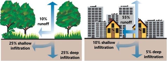
The hydrologic cycle is disrupted and altered when land is developed. Vegetation clearing removes the vegetation that intercepts, slows, and returns rainfall to the air through evaporation and transpiration. Grading flattens hilly terrain and fills in natural depressions that slow and provide temporary storage of stormwater. The topsoil and sponge-like layers of decaying leaves and other organic materials are scraped and removed, and the soil beneath is compacted. Rainfall that once soaked into the ground now runs off the surface in greater volume and at faster velocities. The addition of impervious surfaces (building rooftops, roadways, parking lots and other surfaces) further reduces the amount of water that infiltrates into the soil and groundwater, thus reducing the amount of water that can recharge aquifers and feed streamflow during periods of dry weather. Depending on the magnitude of changes to the land surface, the volume of stormwater runoff can increase dramatically (Figure 1.2.1.2).
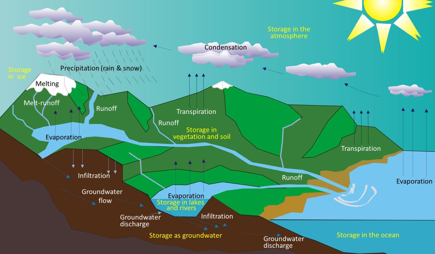
Figure 1.2.1.1 The Natural Hydrologic Cycle (This graphic is licensed under CC BY)
Table 1.2. 1.1 Primary Hydrologic Cycle Processes (Source: www.noaa.gov)
Process Description
Evaporation
Transpiration
Condensation
Precipitation
Runoff
The change in the state of water from a liquid to a gas. The opposite of evaporation is condensation.
The evaporation of water from plants through stomata (small openings on the underside of leaves). Of the transpired water passing through a plant, only 1% is used by the plant. The remaining 99% evaporates into the atmosphere.
The change in the state of water from a gas to a liquid. In the atmosphere, condensation may appear as clouds or dew. The opposite of condensation is evaporation.
Precipitation results when atmospheric condensation grows too large for the rising air to support, and thus falls to the earth. Precipitation can be in the form of rain, hail, snow, or sleet.
Runoff occurs when there is excessive precipitation, and the ground cannot absorb any more water. Some runoff evaporates into the atmosphere, some percolates into the soil and is taken into plants for transpiration. The remainder flows into streams, rivers, lakes, and ultimately, the ocean.
1.2.1.2 The Impact of Impervious Surfaces on the Hydrologic Process (Source: United States EPA)
In addition to increasing the volume of stormwater, changes due to development also accelerate the rate at which stormwater flows across the land. This acceleration is intensified by drainage systems such as gutters, stormwater conveyance systems and lined channels that are designed to quickly drain stormwater away from roadways and structures, and it to local waterways.
Finally, development and urbanization affect not only the quantity of stormwater, but also its quality. Development increases both the concentration and types of pollutants carried by stormwater. As it runs over rooftops and lawns, parking lots and industrial sites, stormwater picks up and transports a variety of pollutants to downstream waterbodies. The loss of the original topsoil and vegetation removes a valuable filtering mechanism for stormwater.
The cumulative impact of development and urban activities, and the resultant changes to both stormwater quantity and quality in the entire land area that drains to a stream, river, or lake, determines the conditions of the waterbody. The land area that drains to the waterbody is known as its watershed. Land development within a watershed has a number of direct
Figure
impacts on downstream waterways. These impacts include changes to stream flow, changes to stream geometry, degradation of aquatic habitats, and water quality impacts.
1.2.2 Changes to Stream Flow
Urban development alters the hydrology of watersheds and streams by disrupting the natural water cycle, which typically results in the negative impacts summarized below.
Increased Stormwater Volumes – Land surface changes can dramatically increase the total volume of stormwater generated.
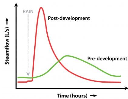
Increased Stormwater Peak Discharges – Increased peak discharges of stormwater for a developed watershed can be two to five times higher than those for an undeveloped watershed. Streams in developed areas are often characterized as very “flashy” or “spiky” because of the increased volume of stormwater, greater peak flows, and quicker hydrologic response to storms. This translates into the sharp peak and increased size of the post-development hydrograph that site designers must mitigate through detention and retention (Figure 1.2.2.1).
Figure 1.2. 2.1 Stormwater Hydrograph Differences (Source: mde.state.md.us)
Greater Stormwater Velocities – Impervious surfaces and compacted soils, as well as improvements to the drainage system such as storm drains, pipes, and ditches, increase the speed at which rainfall runs off land surfaces within a watershed.
Altered Watershed Timing – As stormwater velocities increase, it takes less time for water to run off the land and reach a stream or other waterbody.
Increased Frequency of Stream Overtopping – Increased stormwater volumes and peak flows increase the frequency and duration of bank full events, which are the primary channel forming events.
Increased Flooding – Increased stormwater volumes and peaks also increase the frequency, duration, and severity of outof-bank flooding.
Lower Base Flows (Dry Weather Flows) – Reduced infiltration of stormwater causes streams to have less base flow during dry weather periods and reduces the amount of rainfall recharging groundwater aquifers.
1.2.3 Changes to Stream Geometry
The changes in the volume and velocity of stormwater from developed watersheds directly affect the morphology, or physical shape and character, of creeks and streams. This is depicted graphically in Figure 1.2.3.1 and described in the paragraphs below.
Chapter 1. The Need for Water Quality Control
Figure 1.2.3.1
Physical Stream Changes Due to Watershed Development
Stable Channel

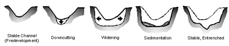


(Predevelopment) Downcutting Widening Sedimentation Stable, Entrenched
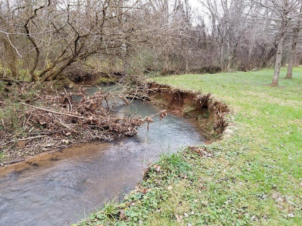
Stream Widening, Bank Erosion, and Streambed Changes – Stream channels widen to accommodate the increased stormwater from developed areas. Frequent small and moderate stormwater events undercut and scour the lower parts of the stream bank, causing the steeper banks to erode and collapse during larger storms. Higher flow velocities further increase stream bank erosion rates. A stream can widen to many times its original size due to post-development stormwater. Sediments accumulate in various areas of the stream, covering the channel bed, or substrate, with shifting deposits of mud, silt, and sand. The photo in Figure 1.2.3.2 is an example of bank erosion, stream widening, and changes to the streambed due to sedimentation.
Stream Downcutting – Another way that streams accommodate higher flows is by down-cutting the streambed. This causes instability in the stream profile, or elevation along a stream’s flow path, which increases velocity and triggers further channel erosion both upstream and downstream.
Loss of Riparian Tree Canopy – As streams are gradually undercut and slump into the channel, the trees that had protected the banks are exposed at the roots. This leaves them more likely to be uprooted during major storms, further weakening the bank structure.
Changes in the Channel Bed Due to Sedimentation – Due to channel erosion and other sources upstream, sediments are deposited in the stream as sandbars and other features, covering the channel bed, or substrate, with shifting deposits of mud, silt, and sand.
Increase in the Floodplain Elevation –To accommodate the higher peak flow rate, a stream’s floodplain elevation typically increases following development in a watershed due to higher peak flows. This problem is compounded by building and filling in floodplain areas, which cause flood heights to rise even further. Property and structures that had not previously been subject to flooding may now be at risk.
1.2.4 Impacts to Aquatic Habitat
Along with changes in stream hydrology and morphology, the habitat value of streams diminishes due to development in a watershed. Impacts on habitat include:
Figure 1.2.3.2 Stream Changes (Source: City of Maryville, TN)
Northeast
Degradation of Habitat Structure – Higher and faster flows due to development can scour channels and wash away entire biological communities. Streambank erosion and the loss of riparian vegetation reduce habitat for many fish species and other aquatic life, while sediment deposits can smother bottom-dwelling organisms and aquatic habitat.
Loss of Pool-Riffle Structure – Streams draining undeveloped watersheds often contain pools of deeper, more slowly flowing water that alternate with “riffles” or shoals of shallower, faster flowing water. These pools and riffles provide valuable habitat for fish and aquatic insects. As a result of the increased flows and sediment loads from urban watersheds, the pools and riffles disappear and are replaced with more uniform, and often shallower, streambeds that provide less varied aquatic habitat.
Decline of Abundance and Biodiversity – When there is a reduction in various habitats and habitat quality, both the number and the variety, or diversity, of organisms (wetland plants, fish, macro-invertebrates, etc.) are also reduced. Sensitive fish species and other life forms disappear and are replaced by those organisms that are better adapted to the poorer conditions. The diversity and composition of the benthic, or streambed, community are frequently used to evaluate the quality of urban streams. Aquatic insects are a useful environmental indicator as they form the base of the stream food chain.
Fish and other aquatic organisms are impacted not only by the habitat changes brought on by increased stormwater quantity but are often also adversely affected by water quality changes due to development and resultant land use activities in a watershed.
1.2.5 Water Quality Impacts
Stormwater is a major source of water quality impacts in streams, lakes, and other waterbodies. Water quality degradation in urbanizing watersheds starts when development begins. Stormwater washes sediment, pet waste, fertilizers, and other pollutants from rooftops, pavement, and landscaped areas, and also erodes bare soil. These pollutants are carried in stormwater to local waterways where they can have a myriad of impacts. Common stormwater pollutants include the following:
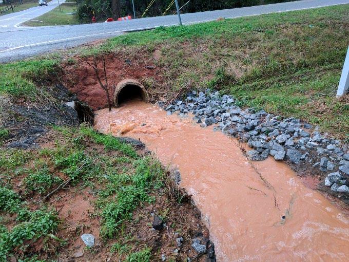
Sediment – The single most important water quality problem in the United States is sediment dislodged from exposed soil, stream banks, and channel beds (Figure 1.2.5.1). Excessive sediment can be detrimental to aquatic life by interfering with photosynthesis, respiration, growth, and reproduction.
Nutrients – S tormwater from urban watersheds contains increased nutrients such as nitrogen and/or phosphorus compounds. In an urban setting, nutrients in stormwater primarily come from fertilizers, lawn, and landscape.
Pathogens – Pathogens harmful to human health consist of bacteria, protozoa, viruses, and other microscopic organisms. The sources of pathogens in urban stormwater include leaking private or public sewer lines, combined sewer overflows, malfunctioning septic tanks, and wastes from animals, pets, and birds.
Hydrocarbons – Oils, greases, and gasoline contain a wide array of hydrocarbon compounds, some of which have been shown to be carcinogenic, tumorigenic, and mutagenic in various species of fish and other lifeforms. In large quantities, oil can impact drinking water supplies and affect recreational use of waters. Oils and other hydrocarbons wash off roads and parking lots, primarily due to vehicle leaks. Other sources include improper disposal of motor oil in storm drains and streams, spills at fueling stations, and restaurant grease traps.
Reduced Oxygen in Streams – Stormwater laden with lawn and landscape waste, pet waste, and other sources, delivers organic matter to local streams. While organic material is necessary for aquatic life, an overabundance of organic matter can contribute stream impacts. The decomposition of this matter uses up dissolved oxygen (DO) in the water, which is vital for fish and other aquatic life. When combined with increased algae and weed growth due to nutrient loading, DO levels rapidly deplete causing fish kills and other stream health i mpacts.
Toxic Materials – Besides oils and greases, urban stormwater can contain a wide variety of other toxicants and compounds, including heavy metals like lead, zinc, copper, and cadmium, as well as organic pollutants that include pesticides, polychlorinated biphenyls (PCBs), and phenols. These contaminants are of concern because they are toxic to aquatic organisms and can bio-accumulate in the food chain, especially in areas like Mobile where fish and other aquatic species are significant and cherished as a food source. Sources of these contaminants in urban stormwater include industrial and commercial areas, urban surfaces like rooftops and roadways, vehicles, and other machinery, improperly disposed household chemicals, landfills, hazardous waste sites, and atmospheric deposition.
Thermal Pollution – As stormwater flows over impervious surfaces, such as asphalt and concrete, it increases in temperature before reaching a stream or pond. Water temperatures are also increased due to detention and impoundments along a watercourse and fewer trees along streams to shade the water. Since warm water holds less DO than cold water, this “thermal pollution” further reduces oxygen levels in urban streams. Temperature changes can severely impact certain aquatic species, such as trout and stoneflies, which can survive only within a narrow temperature range.
Trash and Debris – Considerable quantities of trash and other debris are washed through storm drain systems and into streams and lakes. The presence of trash is an indicator of other anthropomorphic effects on water quality, stream structure, and aquatic habitat. Terrestrial and aquatic animals can be harmed when they consume or become entangled/engulfed in solid waste.
1.2.6 Impacts on Communities
The stormwater impacts of land development and gradual urbanization on local communities can be significant if not mitigated. These issues range from physical to environmental to economic, but all of them stem from two primary impacts: increased flooding and reduced water quality. Community impacts can include:
Increased Flooding – As more land development occurs without proper stormwater management, our natural and man-made infrastructure becomes more vulnerable to flooding, which is a result of the increased stormwater peak flow rates and volumes resulting from the land development.
Environmental Issues – As pollutants in stormwater enter local waterways, they threaten aquatic life and drinking water supplies, can contribute to human illness, and damage tourism and recreation economies.
Economic Challenges – Local governments are typically charged with resolving the flooding, erosion, and environmental issues caused by increased stormwater. The financial cost to repair known issues and prevent further
Figure 1.2.5.1 Excessive Sediment in Stormwater
Northeast
occurrences can sometimes be significant, competing directly against other government priorities (e.g., police, fire, schools) for funding.
Declining Property Values – Stormwater pollution affects the appearance and quality of downstream waterbodies, influencing the desirability of working, living, traveling, or owning property near the water. Furthermore, the value of property located in areas with a high potential or increasing history of flooding will also decrease.
Loss of Fisheries – Certain toxic chemicals present in streams, lakes, and rivers resulting from polluted stormwater inflows can accumulate in fish, especially in older and larger fish. When chemical concentrations are elevated in fish, they can pose health risks to people who eat them.
Reduced Drought Resiliency – Increased stormwater volumes reduces the amount of rainfall available to recharge shallow groundwater aquifers and feed freshwater rivers and streams during dry weather. Thus, streams have lower base flow and are less able to withstand extended periods of drought.
Increased Litigation – Legal action can be brought against local governments that have not adequately addressed stormwater drainage and water quality problems.
Reduction in Quality of Life – All of the impacts listed above result in a decline in the quality of life in a community, making it a less desirable place to live, work, and play.
1.2.7 Urbanization and Stormwater in Northeast Tennessee
The transformative shift in the hydrological dynamics of northeast Tennessee began in the early 1800s, when substantial development of the region began. Interest in the area was primarily attributed to the region's accessible rivers, utilized for transportation, and freshwater streams that served as vital sources of sustenance for early settlers. Kingsport, Johnson City, and Bristol emerged as the primary cities due to the abundance of natural resources and the expansion of the railroads in the mid-1800s. Growth continued in the early 1900’s when the Tennessee Valley Authority (TVA) pushed electrification initiatives through the construction of the Wilbur Dam near Elizabethton. This growth necessitated the removal of native soil and plants through extensive mass grading to accommodate the burgeoning urban centers and their surrounding neighborhoods. The use of fill soil became prevalent for supporting building foundations and leveling pavements, resulting in a landscape dominated by impervious surfaces like rooftops, roadways, and parking lots; outweighing the presence of plants and other vegetation (see Figure 1. 2.7.1).
The transformation of urban areas triggered substantial changes in two key elements of the water cycle soil and land cover leading to increased stormwater volumes, heightened peak discharges, and elevated pollutant levels. These alterations brought about extensive modifications in natural surface water systems within these urbanizing areas. Northeast Tennessee’s towns and cities especially felt the impact, grappling with channel erosion and widening and heavy sediment accumulation, resulting in flooding in previously unaffected areas.
In response, cities, towns, and private property owners sought to overhaul overwhelmed natural drainage systems. Streams, tributaries, and drainageways underwent concrete reinforcement and channelization to accommodate the amplified flows stemming from impermeable urban surfaces. While these redesigned
Chapter 1. The Need for Water Quality Control

Figure 1.2.7.1 Broad Street in Kingsport, 1958 (David Peirce)
Northeast Tennessee Water Quality SCM
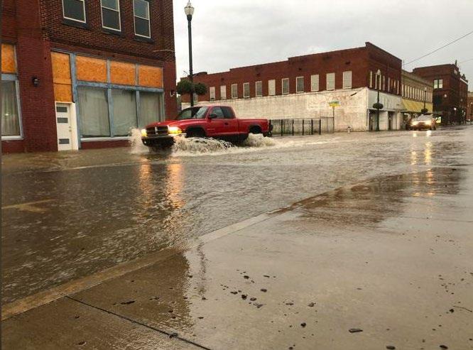
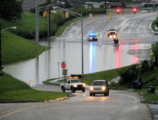
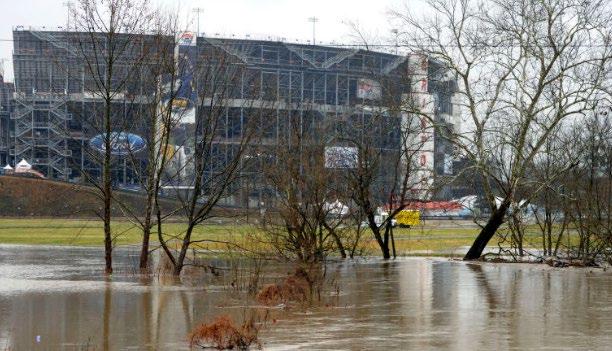
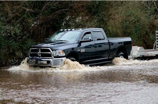
drainage systems were intended to swiftly divert water from structures and roads, they resulted in hydrographs characterized by rapid fluctuations in discharge and velocity (GMC, 2017). Regrettably, in certain locales, localized flooding remains a persistent issue following heavy rainfall, as illustrated in Figure 1. 2.7.2. Moreover, several local streams in the region have received official designation as impaired by the State of Tennessee due to the detrimental effects of urban stormwater.
1.3 Addressing Stormwater Impacts

West Market Street, Johnson City TN July 2020 (Source: Johnson City Press); East Sullivan Court, Kingsport July 2020 (Source: Kingsport Times News; Photo by John Osborne); Bristol Motor Speedway March 2021 (Photo: AP/Wade Payne); George Brown Road Elizabethton TN December 2018 (City of Elizabethton TN).
Local governments address the stormwater impacts stemming from land development through a mix of solutions. First, public stormwater infrastructure improvements, called capital improvement projects, are undertaken most often to address stormwater impacts that are already being experienced as a result of existing developments. However, most of these projects are planned with consideration of the future growth in a community Second, stormwater regulations are an effective tool many local governments use to keep existing stormwater problems from getting worse, or better yet, to prevent negative stormwater impacts entirely. These regulations require:
Controlling stormwater discharges from frequent storm events to reduce pollutants discharged from a land development and prevent downstream streambank channel erosion.
Establishing vegetated buffers along local waterways.
Controlling stormwater from larger storms to reduce flooding on private and public properties.
Using the most current and effective erosion prevention and sediment control (EPSC) practices during the construction phase of development
Northeast Tennessee Water Quality SCM Manual
Implementing pollution prevention practices to prevent stormwater from becoming contaminated in the first place.
Proactively managing land development within and near local floodplains.
This manual was developed to support the post-construction stormwater quality requirements for Johnson City, Kingsport, Bristol, and Elizabethton, Tennessee. Thus, it establishes the requirements for the first two bullets listed immediately above and addresses the third and fourth bullets to a lesser degree. Table 1.3.1 briefly summarizes the stormwater management standards and related tools addressed in this manual.
Table 1.3.1 Summary of Stormwater Management Standards
City
Water Quality Management Plan (WQMP)
Water Quality Volume (WQv)
Downstream Channel Protection Volume (CPv)
Flood Control (Detention/Retention)
Downstream Impact Analysis (the 10% Rule)
Low Impact Development (LID)
Stormwater Control Measures (SCMs)
Vegetated (Water Quality) Buffers
Description
The water quality management plan (WQMP) is the design plan for proposed new and redevelopments that indicates how stormwater quality will be addressed. The WQMP is discussed in Chapter 2.
The WQv is the portion of the stormwater generated by a new or re-development project that must be treated to reduce stormwater pollutants discharged from the property. WQv is fully described in Chapter 3.
Local streams are susceptible to erosion and degradation due to increased flows and flow durations. Therefore, criteria are established to protect stream channels through the capture and extended detention of a specified stormwater volume. Channel protection requirements are presented in Chapter 3.
Each local government has requirements for peak discharge control using detention or retention of stormwater. These requirements are established in local stormwater ordinances (see Table 1.1.4.1). Design storms are listed in Appendix B
The downstream impact analysis is an evaluation of the impact of stormwater detention at a new/re-development downstream of the property. The goal is to identify and prevent unintended stormwater impacts of a development downstream This analysis is fully described in Chapter 3
LID practices are site layout and design approaches that minimize the amount of stormwater generated on a land development. The use of LID practices is not required. LID practices are addressed Chapter 4.
SCMs are structural facilities constructed for the purpose of controlling stormwater generated by a land development. Depending on their design, SCMs can control stormwater quality and/or quantity, and provide downstream channel protection. SCMs are generally described and compared in Chapter 3. Their design specifications are provided in Chapter 5.
Vegetated buffers are permanent strips of natural perennial vegetation adjacent to a stream, river, wetland, pond, or lake that contains dense vegetation made up of grass, shrubs, and/or trees. The purpose of a vegetated buffer is to maintain existing water quality by minimizing the risk of any potential sediments, nutrients, or other pollutants reaching adjacent surface waters and to further prevent negative water quality impacts by providing canopy over adjacent waters. Vegetated buffers are addressed in Chapter 6
Chapter 1. The Need for Water Quality Control
1.4 References
Fairfield (OH) Soil& Water Conservation District. (2023, December 19). Stream Bank Stabilization . https://fairfieldswcd.org/stream-bank-stabilization/ GMC, Dog River Watershed Management Plan. Submitted to the Mobile Bay National Estuary Program. September 5, 2017.
Kingsport (TN) Public Library. (2023, December 19). David Peirce Collection, 1950-1968. https://www.kingsportlibrary.org/finding_aids/david-peirce-collection-kcmc-258/
Maryland Department of the Environment. 2000. Maryland Stormwater Design Manual, Volumes I and II. Center for Watershed Protection (CWP), Ellicott City, MD.
National Oceanic and Atmospheric Administration (NOAA). (2023, December 19). The Hydrologic Cycle www.noaa.gov/Jetstream/atmosphere/hydro
United States Environmental Protection Agency (EPA). (2023, December 19). Urbanization – Stormwater Runoff https://www.epa.gov/caddis-vol2/urbanization-stormwaterrunoff#:~:text=Stormwater%20Runoff%20and%20Impervious%20Surfaces&text=Impervious%20surfaces%20asso ciated%20with%20urbanization,associated%20contaminants)%20reach%20urban%20streams
CHAPTER 2: RELEVANT REGULATIONS AND
Northeast Tennessee Water Quality SCM
2.1 Introduction
The purpose of this chapter is to provide general information on the land development planning process, regulations, and plans as they relate to stormwater management. This chapter contains general information regarding the roles and requirements of the local government and other agencies that have a role in the development process. The reader is referred to the local government or agency of interest for detailed information on development process and procedures.
2.2 Applicable Regulations
2.2.1
Local Regulations
Table 2.2.1.1 presents contact and regulatory information for the local governments that produced this manual. The policies, criteria, and guidance provided in this manual are applicable only to stormwater management designs as required by the ordinances listed in the table. Contact the local government to find out if they participate in the State of Tennessee’s Qualifying Local Program (QLP). There may be additional requirements for plan submissions. See Section 2.2.2 below for more information on the QLP.
2.2.1.1 Relevant Local Government Ordinances
City of Johnson City, TN
Public Works – Engineering Division (423)434-6080
Email: pwengineering@johnsoncitytn.org
Physical Address:
City of Johnson City
Public Works - Engineering Division 209 Water Street
Johnson City, TN 37601
Mailing Address:
City of Johnson City Public Works - Engineering Division P.O. Box 2150 Johnson City, TN 37601
City of Kingsport, TN
Stormwater Services Division
Water Services Operations Center 1113 Konnarock Road
Kingsport, TN 37664 (423) 229-9454
Email: WSEngineers@KingsportTN.gov
City of Bristol TN
Engineering Division (423) 989-5523
Email: stormwater@bristoltn.org
Physical Address: 212 Blackley Road Bristol, TN 37620
City of Elizabethton, TN
Utilities Department
Phone: (423) 547-6238
Mailing Address: P.O. Box 1189 Bristol, TN 37621
Email: stormwater@cityofelizabethton.org
Physical Address:
City of Elizabethton Engineering Dept
217 Sycamore Shoals Dr. Bldg 1 Elizabethton, TN 37643
Mailing Address: City of Elizabethton Engineering Dept 136 S. Sycamore St. Elizabethton, TN 37643
City of Johnson City Code of Ordinances
Title 14, Chapter 3 Stormwater Ordinance
Code of Ordinances of the City of Kingsport TN
Part II, Chapter 38, Article III Stormwater Management
City of Bristol TN Code of Ordinances Chapter 74, Article VII
Post-Construction Water Quality Management
City of Elizabethton Municipal Code
Title 18, Chapter 6 Stormwater and Water Quality Issues
Table
Northeast Tennessee Water Quality SCM Manual
Persons responsible for the design and construction of a development or redevelopment must also comply with the local government’s relevant ordinances, permits, and regulatory mechanisms for regulations and policies that are not included in this manual. Such regulations may include, but are not limited to, zoning ordinances, minimum subdivision regulations, erosion prevention and sediment control ordinances, grading and building permits, and ordinances that regulate drainage and water quantity.
2.2.2 Tennessee Construction General Permit
The State of Tennessee General NPDES Permit for Discharges of Stormwater Associated with Construction Activities is henceforth referred to as the “Construction General Permit” (TNCGP). Applicable to all areas of the State of Tennessee, the TNCGP is intended to regulate the pollution prevention and the control of wastes during construction activities, whereas the Water Quality Management Plan (WQMP) required by Johnson City, Kingsport, Bristol, and Elizabethton, Tennessee is intended to regulate the control of pollution from a land development after its construction. Specific to site developments, the TNCGP emphasizes the application of best management practices (BMPs) for purposes of erosion prevention and sediment control (EPSC) and the control of other construction related materials and wastes. The TNCGP is administered by the Tennessee Department of Environment and Conservation (TDEC).
Note about Qualifying Local Programs (QLPs): When requested by a local government, TDEC can formally recognize a municipal ESPC program that meets or exceeds the provisions of the TNCGP. When this occurs, the TNCGP is administered by the local QLP. Thus, design professionals submit Notices of Intent, and Stormwater Pollution Prevention Plans (SWPPPs) to the QLP for approval, as opposed to TDEC .
2.2.3 Aquatic Resource Alteration Permit
Persons who conduct any activity that involves construction within, and potentially the alteration of, waters of the state must obtain a state Aquatic Resource Alteration Permit (ARAP), and possibly a Federal Section 401 Certification. Examples of stream alterations that require a permit include:
Bank Sloping; stabilization
Channel relocation
Water diversions or withdrawals
Road and utility crossings
Dredging, excavation, channel widening or straightening
Dams, weirs, dikes, levees, or other similar structures
Structural fill
Flooding, excavating, draining and/or filling a wetland
ARAPs and 401 Certifications are administered by TDEC. The Section 401 Certification is required for projects involving the discharge of dredged or fill material into waters of the United States (US), or wetlands. An ARAP is required for any alteration of state waters, including wetlands that do not require a federal permit.
2.2.4 26a Permits for Shoreline Construction
The Tennessee Valley Authority (TVA) administers a permit program that governs shoreline construction along, across, or in the Tennessee River or any of its tributaries. Thus, TVA’s jurisdiction for the 26a permit extends to the limits of the Tennessee River watershed. In accordance with TVA requirements, the permit applies to construction in the 500-year floodplain or to the upper limits of TVA flowage rights, whichever is higher, for developments located along regulated rivers (tailwaters) and TVA reservoirs (e.g., Boone Lake). Along off-reservoir unregulated streams and rivers, jurisdiction is typically applied to the limits of the 100-year floodplain. More information on the TVA 26a permit can be found at http://www.tva.gov
2.2.5 State/Federal Water Quality Regulations
Two major regulatory programs provide the basis for local government water quality regulations: the General Permit for Discharges from Small Municipal Separate Storm Sewer Systems (MS4s); and the Total Maximum Daily Load (TMDL) program. Both programs are administered by TDEC. For local governments subject to the MS4 permit, the TMDL program
Northeast Tennessee Water Quality SCM Manual
is largely implemented through permit conditions. Relevant to post-construction stormwater requirements for land developments, local government compliance with the permit is established through the water quality management regulations on new developments and redevelopments in the ordinances listed in Table 2.2.1.1.
More information on MS4 permit compliance programs in Johnson City, Kingsport, Bristol, and Elizabethton can be found on each jurisdiction’s website.
2.3 The Water Quality Management Plan (WQMP)
The Water Quality Management Plan (WQMP) is the engineering plan for the design of SCMs and vegetated buffers. It is required for all new and re-developments subject to local government stormwater quality requirements. It will be reviewed by the local government for compliance with the ordinance, this manual, and any other applicable local requirements.
WQMP preparation, submittal, and adherence requirements are established in the local government’s post-construction stormwater ordinance (see Table 2.2.1.1). The list of required elements for the WQMP is provided in the plan preparation checklist located in Appendix D. Several of the notable sub-plans and reports included in the WQMP are described below.
2.3.1 Pre-Development Hydrology Map
The purpose of the Pre-Development Hydrology Map is to assist design professionals in formulating an effective postdevelopment stormwater management strategy for a property based on its pre-development hydrologic condition. This is a standard low impact development (LID) technique with the goals of minimizing stormwater volumes and maximizing natural hydrologic function after development.
This technique is best performed early in the development planning process, before the layout of roadways, driveways, and buildings is designed for a subdivision or site, and before clearing and grading This allows design professionals to identify opportunities for inexpensive, natural stormwater management approaches (i.e., low impact development practices) prior before these areas are altered by clearing and grading. Preparation of this report is largely a mapping exercise using available data and visual observations. Calculations and onsite tests are not required.
More information on the Pre-Development Hydrology Map is provided in Chapter 4 (Low Impact Development Practices) and in the plan preparation checklist in Appendix D
2.3.2
Post-Construction Hydrology Report
The Post-Construction Hydrology Report is the most intensive portion of the WQMP as it documents the proposed design for SCMs and vegetated buffers. Detailed evidence, including site maps, SCM design diagrams, and accompanying data, parameters, specifications, and certifications, is required in the report to show that the proposed design(s) comply with the design standards and specifications provided in the local ordinance (see Table 2.2.1.1) and this manual. The list of required elements for the report is provided in the WQMP plan preparation checklist in Appendix D
2.3.3
SCM Vegetation Report
Plants are important components in many SCMs. At a minimum, they prevent erosion within or near the SCM. In some SCMs, they are key to pollutant removal, providing filtration and evapotranspiration. Thus, plants must be thoughtfully considered as a deliberate stormwater management feature when designing many SCMs. For this reason, many SCM design specifications include standards for vegetation. For these SCMs, a vegetation report, with associated design plans, is required as part of the WQMP. The list of required elements for the report is provided in the WQMP plan preparation checklist in Appendix D. Vegetation design specifications and plant selection guidance are included in the SCM design specifications located in Chapter 5
Northeast Tennessee Water Quality SCM Manual
Design professionals who may not have extensive knowledge of vegetation design are encouraged to gain vegetation design assistance from a landscape architect or reputable landscape professional to properly tailor the design to the sitespecific and soil-specific conditions.
2.3.4 SCM Protection Report
The SCM Protection Report is prepared to document the permanent protective measures to be employed onsite to protect proposed SCMs from unwanted entry and damage.
2.3.5
SCM Maintenance Report
The SCM Maintenance Report is prepared to: 1) document the type and location of each SCM proposed for the development; and 2) show how the SCM designs support their future maintenance.
2.4 Record Drawings
Terminology for record drawings varies among Johnson City, Kingsport, Bristol, and Elizabethton TN, depending upon jurisdictional preference. The terms “record drawing”, “as-built drawing”, or “as-built certification” are synonymous. Where the term “record drawing” is used herein, the terms “as-built drawing” or “as-built certification” can be inferred.
Record drawings are prepared at the end of construction to document the as-constructed condition of each SCM for developments subject to an approved WQMP. The purpose of a record drawing is to certify that the development or redevelopment was constructed in accordance with the approved WQMP, and that SCMs are clean, undamaged, and fully functional at the end of construction. Record drawings are recorded, and any restrictions or requirements shown on the record drawings run with the property.
Record drawing preparation and submittal requirements are established in the local government’s post-construction stormwater ordinance (see Table 2.2.1.1). The list of required drawing elements is provided in the plan preparation checklist located in Appendix E Several of the notable sub-plans and reports included in the WQMP are also required in the Record Drawing, modified as necessary to document as-construction condition
2.4.1 Professional Certifications
Property owners are strongly encouraged to field check the location and extents of SCMs, buffers and their associated easements shown on the record drawing to ensure they are correct
Two professional certifications are required with SCM record drawings, as described below. Certifications must be provided for each SCM located on the property.
Land surveyor’s certification Land surveyors providing record drawings must provide the following certification, in addition to the surveyor’s seal and an original signature and date across the seal.
I hereby certify that I have surveyed the easements shown hereon in accordance with the accuracy requirements for a Category I survey and that the ratio for precision of the unadjusted survey is not less than 1:10,000. I further certify that I have located all natural and manmade features shown hereon in accordance with the current Standards of Practice as adopted by the Tennessee State Board of Examiners for Land Surveyors. I certify the locations, extents, elevations, and descriptions of these features.
Northeast Tennessee Water Quality SCM Manual
Professional Engineer’s Certification. The professional engineer’s certification attests that as-built drawing is accurate and that all SCMs are clean, undamaged, and fully operational as intended in the approved WQMP. The following statement must be included in the certification.
I hereby attest that all grading, drainage structures and conveyance systems, SCMs and vegetated buffers are constructed in substantial conformance with approved plans and specifications
Further, I hereby attest that all SCMs and related easements and are accurately depicted on the record drawing.
Further, I further attest that each SCM is clean and free of debris and construction sediment, and fully functional as intended in the approved plans and specifications.
My certification is based upon ( check one):
� site observations made by me or person(s) in my responsible charge; or
� information provided by a registered land surveyor.
2.5 Easements and Plats
Stormwater easements are a legal agreement to grant the local government access to SCMs, vegetated buffers, stormwater conveyances, and related access routes from a public roadway for inspection and maintenance enforcement purposes. The easements are required local government’s stormwater ordinance and must be shown on all land development plans. They are also shown on the plat for the development, and therefore are recorded and run with the property.
Stormwater easements are not SCM maintenance agreements. They do not assign maintenance responsibilities to the local government or any other agency or person. Rather, local government ordinances place the responsibility for SCM maintenance on the property owner. Property owners and design professionals are strongly encouraged to consult their local stormwater ordinance (see Table 2.2.1.1) to ensure that stormwater easements are located, marked, and maintained in accordance with City requirements.
2.6 Bonds and Construction Securities
A performance bond or other form of construction security may be required by the local government for land disturbing activities, and/or the construction of new developments and redevelopments when:
there is a potential for stormwater to adversely impact local rights-of-way, other property, and/or streams, wetlands, ponds, or lakes; or,
an erosion prevention and sediment control plan is required; or,
a WQMP is required; or,
the area of grading or development drains to one or more sinkholes; or,
the site is used for a borrow pit.
The purpose of the performance bond or security is to ensure that the person(s) responsible for completing the land disturbing activities and/or construction work that has the potential to impact the public interest if performed improperly completes the work in an appropriate manner. The bond/security provides assurance to the local government that it will
Northeast Tennessee Water Quality
be reimbursed when it must assume the costs of corrective measures and/or work not completed by the responsible person(s) according to the required specifications and approved plans. The money can be used to cover the local government’s costs for SCMs and related appurtenances, the installation and maintenance of EPSC measures and EPSC corrective actions, final soil stabilization of a site, and the establishment, protection, and maintenance of vegetated buffers.
Performance bonds are administered by the local government. The dollar amount will be determined based on the information presented in the approved EPSC Plan and/or WQMP. Check your local government stormwater ordinance (see Table 2.2.1.1) for more information on required bonds and construction securities.
2.7 References
Knox County, Tennessee. 2007. Knox County Stormwater Management Manual Volume 1 – Administration and Procedures. MWS. 2012. Metropolitan Nashville-Davidson County Stormwater Management Manual Volume 5 Low Impact Development. Metro Water Services. Nashville, TN.
CHAPTER 3: STANDARDS, METHODS &
3.1
Overview
This chapter represents performance standards, calculation methods, and supporting policies for the design and selection of the stormwater control measures (SCMs) presented in Chapter 5 (SCM Design Specifications) of this Manual. The design criteria presented herein communicate the regional approach to address the key adverse impacts of stormwater runoff from a development site presented in Chapter 1 (The Need for Water Quality Management) The purpose of the design criteria is to provide a framework for design of the site’s stormwater management system in order to remove stormwater runoff pollutants, improve water quality, and prevent downstream streambank and channel erosion.
While this manual is focused on stormwater quality management, many SCMs have the capability to provide flood control (i.e., stormwater quantity management), as required by local government ordinances. Each local government has their own design storm standards for flood control. See Chapter 3, Section 3.4 (Storage Design) for more information. As well, this chapter does include design guidance for common flood control design components, such as multi-riser outlets for the design of storage facilities (i.e., detention basins, stormwater wetlands, etc.) and design specifications for storage SCMs are provided in Chapter 5
3.2 Water Quality Management
3.2.1
Background
The cities of Johnson City, Kingsport, Bristol, and Elizabethton, Tennessee are subject to the State of Tennessee’s National Pollution Discharge Elimination System (NPDES) Permit for small Municipal Separate Storm Sewer Systems (MS4). The permit requires the implementation of a stormwater quality management program that reduces the discharge of pollutants in stormwater. Included among the many permit requirements are permanent (post-construction) stormwater standards for new development and redevelopment projects. These standards require the design, construction, and maintenance of stormwater control measures (SCMs) to meet a performance standard of 80% total suspended solids (TSS) removal.
As required by the NPDES-MS4 permit, local government ordinances similarly establish the requirement for stormwater quality treatment for new developments and redevelopments. This section provides the policies and guidance to support the ordinances.
3.2.2 Design Standard and General Policies
The water quality design standard and associated policies for stormwater quality treatment are set forth below.
Stormwater Quality Treatment (WQv) Standard. Stormwater control measures (SCMs) shall be designed to achieve a minimum treatment of 80% TSS removal from the required water quality volume (WQv) for their contributing drainage area Compliance with the stormwater quality treatment standard is achieved through the design and construction of the SCM(s) in keeping with Table 3.2.2.1 and the policies and specifications in this manual.
Table 3.2.2.1 is read by row, with each row equating to 80% TSS removal SCMs are grouped (Columns 1 and 3) by their stormwater treatment mechanism(s) (Column 2). Each SCM group is assigned a minimum WQv (Column 4) that equates to 80% TSS removal 1 . Thus, an SCM must be designed and constructed to treat the minimum WQv for its group to achieve 80% TSS removal For example, if a bioretention area with an underdrain (a Group 2 SCM) is selected for stormwater quality treatment for a drainage area within a development, it must be designed and constructed to treat the runoff volume generated from the first 1.25 inches of the 1-yr, 24-hr storm for that drainage area to meet the stormwater quality treatment standard.
1 The minimum WQv (Column 4) for each SCM treatment mechanism (Column 2) is assigned by the Tennessee Department of Environment and Conservation (TDEC) Rule 0400-40-10- 04 and the NPDES-MS4 permit.
Table 3.2.2.1
SCM Group Treatment Mechanisms
Group 1
Group 2
Infiltration, evaporation, transpiration, or rainfall harvesting and reuse
Biologically active filtration with an underdrain
Group 3 Sand or gravel filtration, settling
Group 4
Pollutant/stormwater separation
Stormwater Control Measure (SCM) (design configuration)
Bioretention Area (no underdrain)
Cistern
Dry Enhanced Swale (no underdrain)
Green Roof
Infiltration Basin
Infiltration MTDs2 (no underdrain)
Permeable Pavement System (no underdrain)
Bioretention Area (with underdrain)
Biofiltration MTDs2 (with underdrain)
Dry Enhanced Swale (with underdrain)
Urban Bioretention (with underdrain)
Dry Extended Detention (ED) Basin
Filtration MTDs1
Permeable Pavement System (with underdrain)
Sand Filter (all types)
Stormwater Wetland
Submerged Gravel Wetland
Water Quality Basin (all types)
Hydrodynamic separation MTDs2
MTD is an acronym for Manufactured Treatment Device. See MTD design specifications in Chapter 5 of this manual.
In addition to treating the required WQv, SCM designs must follow the specifications provided in Chapter 5 of this manual.
Minimum WQv (for 80% TSS Removal2)
The runoff volume generated from the first 1-inch of the 1-yr, 24-hr storm3
The runoff volume generated from the first 1.25 inches of the 1-yr, 24-hr storm3
The runoff volume generated from the first 2.5 inches of the 1-yr, 24-hr storm3 or, 75% of the total runoff volume from the 1-yr, 24-hr storm3 (whichever is less)
Maximum runoff generated from the 1-yr, 24-hr storm3
The water quality treatment design storm is the 1-year, 24-hour storm event for the development location, as defined by the National Oceanic and Atmospheric Administration (NOAA) Precipitation-Frequency Atlas of the United States, latest edition Technical Paper 40 (TP40) shall not be used for rainfall information.
Group 1 SCM feasibility The feasibility of Group 1 SCMs for onsite use must be verified and confirmed in the Water Quality Management Plan (WQMP) SCM feasibility policies are provided in the design specification for the SCM, found in Chapter 5 (SCM Design Specifications) See also the requirements in Appendix C (Infiltration Feasibility Form). A completed form must be provided with the WQMP for each Group 1 SCM proposed for the land development.
3.2.3 Determining the WQv
The following pages describe two different approaches to determine WQv to size a Group 1, 2, or 3 SCMs that are not manufactured treatment devices (MTDs). Site design professionals can choose the approach best suited to their needs. Water quality sizing methods for Group 1, 2, 3, and 4 MTDs are provided in Chapter 5, Section 5.7 (Manufactured Treatment Device)
Approach 1 - The Simple Method
The Simple Method is a technology-based approach to determining WQv which converts a rainfall volume to a runoff coefficient for the purpose of calculating pollutant loads (Schueler, 1987). The method is expressed in Equation 3.2.3.1 Supporting policies and guidance are provided below the equation.
Equation 3.2.3.1 ������������ = ���� ���� �������� ���� ���� ��������
where:
WQv = water quality volume for the SCM drainage area (acre-feet)
P = water quality design rainfall depth for the selected SCM (inches) (seeColumn4inTable3.2.2.1)
Rv = volumetric runoff coefficient,Rv=0.05+0.0092*I whereIisthepercentimperviouscoveroftheSCM’sdrainagearea; whenI=100%,thenRv=0.97; (seePoliciesforWQvCalculationbelowandSection3.2.6 todetermineI)
A = SCM drainage area (acres)
SeePoliciesforWQvCalculationbelow
Approach 2 - The Runoff Hydrograph Method
This approach is grounded in the development of a runoff hydrograph, using:
NRCS 2 hydrologic methodology
the SCM drainage area
rainfall intensity and depth information; and,
the required water quality design rainfall depth for the selected SCM from Table 3.2.2.1
The development of a runoff hydrograph is a laborious process not normally done by hand. For that reason, this discussion is limited to an overview of the basic steps of the Runoff Hydrograph Method. Design professionals will likely use hydrology software adherent to the hydrologic parameters and methods described below to apply the Method
Step 1. Obtain the rainfall intensity and depth for the 1-year, 24-hour storm at the location of the proposed development from the NOAA Precipitation-Frequency Atlas of the United States, latest edition Rainfall from Technical Paper 40 (TP40) shall not be used for determination of the WQv.
Step 2. Determine the SCM drainage area (A) based on Policies for WQv Calculation below.
Step 3. Use NRCS TR-55 hydrologic methods to determine the Curve Number (CN), Time of Concentration (tc), and any other site-specific parameters to develop a hydrograph for the SCM drainage area (A).
Step 4. Develop the hydrograph for the SCM drainage area (A) using the site-specific rainfall information obtained in Step 1 and site-specific data determined in Steps 2 and 3.
2 NRCS is the acronym for National Resource Conservation Service (NRCS), formerly called the Soil Conservation Service
Step 5. Find the point on the hydrograph when the required rainfall depth (P) from Table 3.2.2.1 (Column 4) is reached on the hydrograph. This point is identified as Tp. This step is often done using tabular hydrograph data; linear interpolation along the rising or falling limb of the hydrograph may be necessary.
For example, if the selected SCM is a bioretention area with an underdrain (a Group 2 SCM in Table 3.2.2.1), the design professional would determine when the first 1.25 inches (per Column 4) is reached on the hydrograph Step 6. WQv is determined by calculating the area under the hydrograph from its start to Tp WQv is equal to the runoff volume for the water quality design rainfall. Figure 3.2.3.1.
For Group 3 SCMs, the design professional has the option of determining the WQv using Steps 1 through 6 described above or setting WQv equal to 75% of the total runoff volume under the hydrograph for the 1-year, 24-hour storm event using Steps 1 through 4. In this option, the total rainfall depth for the 1-year, 24-hour storm at the development location (provided by the NOAA Atlas reference) must be used to generate the hydrograph.
Figure 3.2.3.1 presents a runoff hydrograph for a fictitious development, presuming a Group 3 SCM is selected, and the design professional chooses to size the WQv using the water quality design rainfall of 2.5 inches.
Figure 3.2.3.1 Runoff Hydrograph Showing WQv Determination
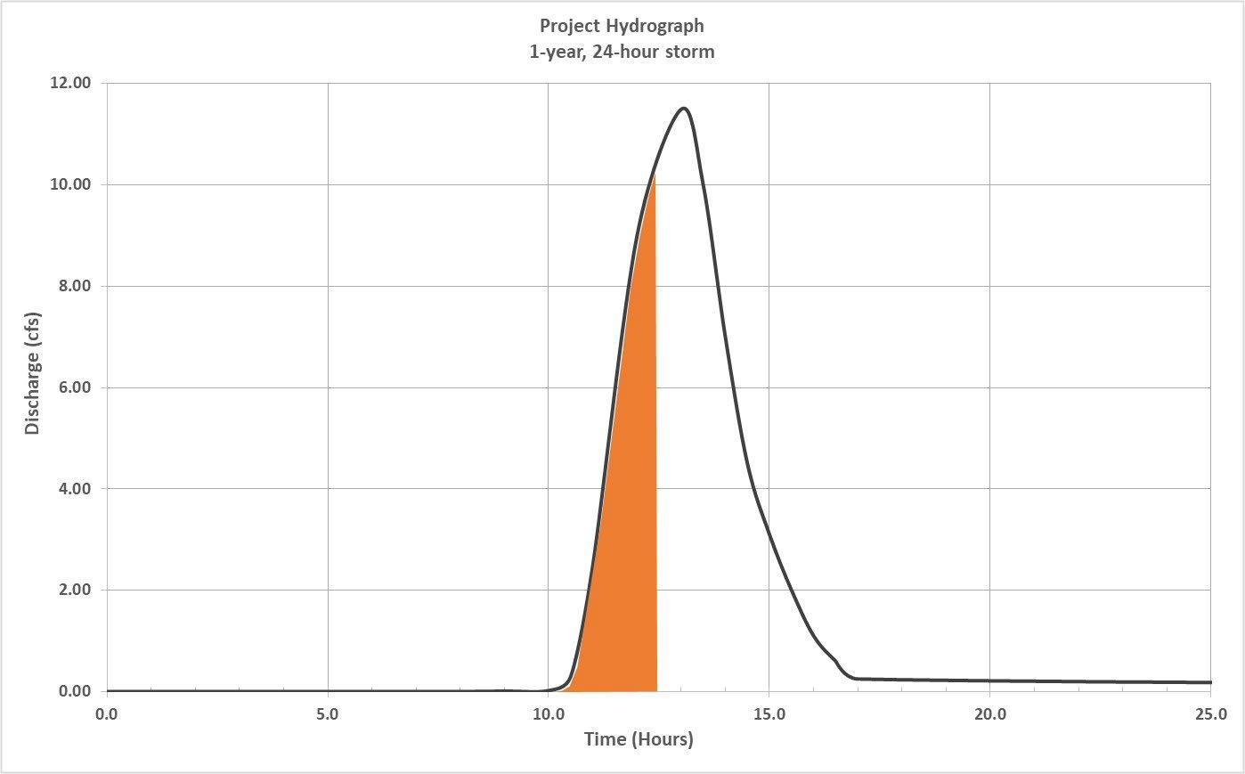
WQv = 6,323 ft3

TP = 12.4 hours

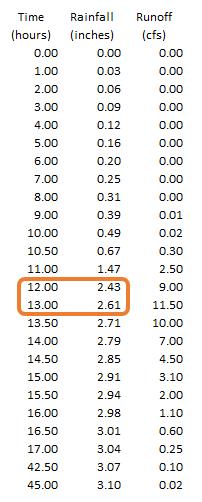
In Figure 3.2.3.1, linear interpolation of the rainfall data generated by the hydrologic modeling software (see the inset) is performed to determine that the first 2.5 inches of rainfall occurs at 12.4 hours (Tp = 12.4 hrs). Thus, the area under the hydrograph up to 12.4 hours is the water quality volume (WQv). This area is shown in orange. The Group 3 SCM, such as a sand filter, would be sized for WQv = 6,323 ft3.
Policies for WQv Calculation
The following policies shall apply to the calculation of WQv for all SCMs, regardless of the method used to determine WQv. SCM Drainage Area (A) Composition. The SCM drainage area (A) must include all areas that drain stormwater to the SCM, inclusive of different land cover types (pervious and impervious) within the area. Ideally, the area draining to the SCM would be composed entirely of impervious surfaces (e.g., rooftop and/or pavement). This situation is the most efficient and effective use of the SCM. However, it is not always feasible to separate stormwater flows from different land covers within a single drainage area. For example, stormwater generated from a residential subdivision is often a mix of runoff from residential lawns and landscapes, rooftops, driveways, sidewalks, and streets. In this situation, it is difficult to separate stormwater discharges by their land cover sources. Thus, the WQv is determined inclusive of all land cover types that will discharge stormwater to the SCM.
WQv Routing. The WQv (and any other post-development condition discharges that will flow through the SCM) must be routed at appropriately small time intervals through SCMs using either hand calculations or computer models that are widely accepted among engineering professionals to ascertain whether the SCM as designed can manage expected flows. The Qwq must be determined via the procedure described in Section 3.2.5. It cannot be determined using traditional hydrologic methods (i.e., Rational Method, NRCS method, etc.).
Interior SCMs. An SCM drainage area may include one or more interior SCMs that serve small, distinct areas located inside a larger drainage area. For example, the drainage area to a dry extended detention (ED) basin may include interior SCMs (such as a permeable pavement system or green roof, and areas discharging to cisterns). The drainage areas for these interior SCMs shall not be excluded from the larger SCMs Drainage Area (A) in Equation 3.2.3.1. However, the volume managed by interior SCMs (typically this will be the WQv for their own, interior drainage areas) can be used to reduce of the larger SCM’s WQv using policies defined for treatment trains (see Section 3.2.4 below)
3.2.4 Treatment Trains
When the SCM selected for stormwater quality treatment does not have the capacity to treat the entire WQv for its drainage area as required by Table 3.2.2.1, the design professional has two choices.
1. A different SCM can be selected, provided it has the capacity to treat its entire WQv.
2. Another SCM is located upstream or downstream of the selected SCM in a treatment train approach. A treatment train is formed when two SCMs are placed in series (i.e., an upstream SCM discharges to a downstream SCM). Treatment train designs shall adhere to the following policies
Treatment Trains using MTDs. Treatment trains that include an MTD shall be designed in accordance with policies set forth in found in Chapter 5 Section 5.7.7 of this Manual.
Treatment Trains without MTDs. Group 3 SCMs must always be the downstream SCM in the series when used in a treatment train with a Group 1 or 2 SCM located upstream in the series.
The WQv from the upstream SCM in the series may be subtracted from the WQv of the downstream SCM to determine the design treatment volume for the downstream SCM. Equation 3.2.4.1 is used to determine the design treatment volume for the downstream SCM. Example 3.2.4.1 illustrates this policy.
Equation 3.2.4.1
where:
���������������� = �������������������� ����������������
Tvds = the design volume of the downstream SCM (acre-feet)
WQvds = the WQv of the downstream SCM (acre-feet) (seeEquation3.1)
Tvus = the design volume of the upstream SCM (acre-feet)
Example 3.2.4.1 Volume Calculation for a Treatment Train using Group 2 and 3 SCMs
A site designer is designing SCMs for a proposed small commercial development in Johnson City TN. The development has a total area of 2 acres, all of which is impervious and located within a single drainage area. The designer wants to use a dry enhanced swale to convey stormwater from the impervious area to a traditional detention basin. They calculate the required WQv.
Step 1: Calculate the WQv for the dry enhanced swale as prescribed by Table 3.2.2.1 (a Group 2 SCM, P = 1.25 inches).
The site designer decides to use the Simple Method to calculate WQv.
WQv = (P x Rv x A) ÷ 12; where Rv = 0.97 for a 100% impervious drainage area
WQv = (1.25 inches x 0.97 x 2.0 acres) ÷ 12
WQv = 0.20 ac-ft
When the designer begins the preliminary design, they determine the swale will not have sufficient capacity to treat its required WQv. The swale has capacity for just 0.15 ac-ft, leaving 0.05 ac-ft of the required WQv left untreated.
The designer decides to modify the detention basin design into a dry extended detention (ED) basin, which is a Group 3 SCM. Two design options are available: 1) the swale can discharge to the ED basin in a treatment train, thus reducing the required treatment volume for the ED basin by the 0.15 ac-ft treated in the swale; or, 2) the swale can be eliminated from the design and the ED basin sized to treat the entire WQv for a Group 3 SCM
The designer opts to include the swale, thus creating a treatment train to meet the 80% TSS removal standard. The required treatment volume for the ED basin is then calculated as follows
Step 2: Using the Simple Method again, calculate the WQv for the ED basin as prescribed by Table 3.2.2.1 (a Group 3 SCM, where P = 2.5 inches).
WQv = (2.5 inches x 0.97 x 2.0 acres) ÷ 12
WQv = 0.40 ac-ft
Step 3: Since the swale and dry ED basin are in a treatment train, calculate the design treatment volume (Tvds) for the ED basin.
Tvds = WQvds - Tvus
Tvds = 0.40 ac-ft – 0.15 ac-ft
Tvds = 0.25 ac-ft
Thus, the water quality portion of the dry ED basin must be designed for a treatment volume 0.25 ac-ft. Together, the dry enhanced swale (upstream SCM) and dry ED basin (downstream SCM) meet the 80% TSS removal standard
3.2.5 Calculating the Water Quality Peak Discharge
The peak rate of discharge for the water quality design storm (Qwq), also called the water quality peak discharge, is needed to size SCM components, such as inlets and flow splitters, especially for offline SCMs. It is also routed through SCMs to ensure they manage the flow from the entire water quality event.
More traditional peak discharge calculation methods are not appropriate for this application for a variety of reasons. First, the use of more traditional methods, such as the Rational Method would require the choosing of an arbitrary design storm event that will differ from required water quality rainfall depths established in Table 3.2.2.1. Further, conventional NRCS methods have been found to underestimate the rate of runoff for rainfall events of less than two inches. This discrepancy
Northeast
in estimating discharge rates can lead to situations where a significant amount of runoff bypasses the SCM due to an inadequately sized diversion structure and leads to the design of undersized bypass channels.
The method employed to calculate the water quality peak discharge uses the volumetric runoff coefficient, Rv, to find the depth of stormwater for the water quality rainfall. The Simplified NRCS TR-55 Peak Runoff Rate Estimation technique (USDA, 1986) is then used to find a unit peak discharge that is combined with the runoff depth to find a peak runoff rate. The procedure to determine Qwq follows.
Step 1. Equation 3.2.5.1 is used to determine the water quality volume (in inches), Qwv.
Equation 3.2.5.1 ������������ = ������������ where:
Qwv = water quality volume (inches)
P = water quality design rainfall depth for the SCM (inches) (seeColumn4inTable3.2.2.1)
Step 2. Equation 3.2.5.2 is used with Qwv to determine the synthetic curve number (CN).
Equation 3.2.5.2 �������� =
Step 3. Determine the time of concentration (tc) for the SCM drainage area, and the initial abstraction (Ia) from Table 3.2.5.1, then compute the ratio Ia/P.
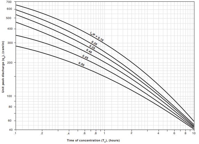
Step 4. The time of concentration (tc) is used with the ratio Ia/P in Figure 3.2.5.1 to obtain the unit peak discharge, qu. If the ratio Ia/P lies outside the range shown in the figure, use the limiting values.
Figure 3.2.5.1 SCS Type III Unit Peak Discharge Graph (Source: NRCS, TR-55, June 1986)
Step 5 The water quality peak discharge (Qw) is then determined using Equation 3.2.5.3.
Equation 3.2.5.3 ������������ = �������� ∗ ���� ∗ ������������ where:
Qwq = water quality peak discharge (cfs) qu = unit peak discharge (csm/in) Note: csm/in = cfs per mi2 of drainage area per inch of runoff A = SCM drainage area (mi2)
Example 3.2.5.1 illustrates calculation of the water quality peak flow.
Example 3.2.5.1 Calculation of the Water Quality Peak Flow, Qwq
Find Qwq for a 50-acre site, with 18 impervious acres The time of concentration (Tc) is determined to 0.35 hours. The proposed SCM is a dry extended detention (ED) basin
Step 0: Compute volumetric runoff coefficient, Rv. See variables under Equation 3.2.3.1.
Rv = 0.05+(0.0092)(I) = 0.05+[0.0092*(18acres/50acres)(100)] = 0.38
Step 1: Compute the water quality volume in inches, Qwv using Equation 3.2.5.1. From Table 3.2.2.1, P = 2.5 inches for a Group 3 SCM.
Qwv = PRv = 2.5(0.38) = 0.95 inches
Example 3.2.5.1 continued
Step 2: Compute the synthetic curve number for the drainage area.
CN = 1000/{10 + 5(2.5) + 10(0.95) – 10[(0.46)2 +1.25(0.95)(2.5)]0.5} = 81
Step 3: Using the CN and Table 3.2.5.1, find Ia and calculate determine Ia/P. Then, Figure 3.2.3.1 to determine qu. Ia = 0.469, from Table 3.2.5.1
Ia/P = 0.1876
qu ≈ 450 csm/in Note: csm/in = cfs per mi2 of drainage area per inch of runoff
Step 5: Calculate Qwq using Equation 3.2 5.1 Qwq = 450 (cfs/mi2)/in)(50 acres/640 acre/mi2)(0.95 inches) = 33.40 cfs.
3.2.6 Calculating the Percent Imperviousness (I)
Impervious areas are defined as impermeable surfaces which prevent the percolation of water into the soil. Impervious surfaces include, but are not limited to, rooftops and paved surfaces such as walkways, sidewalks, parking areas and driveways, patios, pool decks, and athletic courts, and packed gravel or soil.
Impervious Area Calculations for Site Plans and Planned Unit Developments.
Equation 3.2.6.1 is used to calculate the percent impervious area (I) for SCM drainage areas on site plans and planned unit developments.
The total impervious surface in the SCM drainage area (IA) shall be determined from the footprints for all impervious areas as defined above. The footprint for all impervious surfaces in the proposed development and the calculation of IA be shown in the water quality management plan (WQMP)
For downstream SCMs in a treatment train, do not exclude the area addressed by an upstream SCM when determining IA and the SCM drainage area (A) Volumetric credit is given for these areas by subtracting the volume managed by the upstream SCM from the WQv calculated for the downstream SCM. For more information see the treatment train policies established in Section 3.2.4.
Equation 3.2.6.1 ���� = �������� ���� ���� ������������%
where:
I = percent impervious area (%)
IA = total impervious surface area in the SCM drainage area
A = SCM drainage area (acres)
Subdivision designs may not include the layout and sizes of all impervious surfaces. Instead, the design professional may only be able to determine the actual impervious area of subdivision roadways. Determination of IA for these developments shall be done as established in the policy below.
Impervious Area Calculations for Subdivision Developments. For situations where the impervious area is to be determined, use Table 3.2.6.1 to estimate the percent impervious cover (I). The estimates included in the table are taken from land cover descriptions and average percent impervious area estimates from Technical Release 55 (NRCS, 1986).
It is understood that residential subdivision lot sizes will not fall cleanly into one of the categories listed in the table, but rather fall between two lot size categories The design professional has two options. (1) If the overall lot size variability is minor, round up to the higher lot size. A rounded-up estimate will account for future on-lot improvements that add impervious surfaces over time (e.g., driveway expansions, room additions, patio additions, etc.). (2) Determine an overall average lot size using an area-weighting technique.
Table 3.2.6.1 Percent Impervious Area Values (Source: NRCS, TR-55, June 1986)
1 – Includes residential lots and streets. Impervious surface area in common areas (rooftops, parking areas, athletic courts, pool decks, etc.) must be determined based design plans in Equation 3.2.6.1 .
2 – The % impervious value is interpolated from SCS data
Example 3 2.6.1 includes the calculation of the % impervious value for a residential subdivision having variable lot sizes.
Example 3.2.6.1 Calculation of the Percent Impervious Area (I) for a Residential Subdivision
A site design engineer is preparing a water quality management plan for a proposed residential development. The subdivision has a total area of 31 acres and will include 52 residential lots ranging in area from approximately ¼ acre to no greater than 1 acre (as shown in the table below). Three (3) acres will be preserved as an undisturbed forested vegetated buffer located along a stream that crosses the property, and therefore, there is no impervious coverage within these three acres. Another three (3) acres will be utilized for a recreational common area which includes a community pool, tennis courts and an associated parking lot
Due to local topography on the site, the subdivision drains to two separate dry ED basins, herein called SCM A and SCM B. Twelve acres, including the 3-acre vegetated buffer and 3-acre common area, drains to SCM A. The other 19 acres drains to SCM B. Table 1 provides lot size, area, and impervious data for the proposed subdivision.
Determine the % impervious area for each SCM drainage area
Table 1 provides lot size, area, and impervious data for the proposed subdivision.
Since the site will be served by two separate dry ED basins, it is best to determine the impervious area for each basin’s drainage area, rather than the overall impervious area for the site. For ease in calculation, the site design engineer decided not to interpolate impervious area values, preferring to group lots into approximate lot sizes that correspond to Table 3.2.6.1
Step 1: Determine the total impervious area for the portion of each drainage area that is covered by residential lots and associated subdivision roads (IA residential areas). This is done by multiplying the sub-total area of each lot size range (column 3 from the above table) by the corresponding % impervious in that lot size range (column 4 from the above table). Results of this calculation are shown in Table 2
Thus, the portions of the site where residential lots are located are covered by impervious surfaces as follows:
Drainage Area A impervious area from residential lots (IA residential areas A)= 1.23 acres
Drainage Area B impervious area from residential areas (IA residential areas B) = 4.99 acres
Example 3.2.6.1 continued
Table 1
Table 2
Step 2: Determine the impervious area of the common areas located in Drainage Area A using building and pavement footprints shown on design plans Table 3 shows the results of this exercise.
Thus, 2.7 acres of the 3-acre common area, located in Drainage Area A, is covered by impervious surfaces.
Step 3: Calculate the % impervious area (I) for each drainage area of the site using Equation 3.2.6.1 Because the vegetated buffer is entirely pervious, it is not considered in the calculation.
Example 3.2.6.1 continued Table 3 Area Description
Community pool (includes pool, surrounding deck, maintenance building and sidewalk from parking lot)
Tennis court (includes two courts, surrounding paved areas, and sidewalk from parking lot)
For Area A:
A = total area of Drainage Area A = 12 acres
IA = [(IA residential areas A + IA common areas) ÷ A] X 100%
IA = [(1.23 acres + 2.7 acres) ÷ 12 acres] X 100%
IA = [3.9 acres ÷ 12 acres] X 100%
IA = 32.8% = the percent impervious area of Drainage Area A
For Area B:
A = total area of Drainage Area B = 19 acres
IB = (IB residential areas B ÷ A) X 100%
IB = (4.99 acres ÷ 19 acres) X 100%
IB = 26.3% = the percent impervious area of Drainage Area B
3.2.7 Reducing the WQv
The WQv is proportional to impervious area. So, the amount of stormwater requiring treatment increases as impervious area increases. In other words, the more you pave, the more you treat. Therefore, to reduce the amount of stormwater that must be treated, the developer must find ways to reduce site imperviousness. Reductions in imperviousness are beneficial from a stormwater quality management standpoint. They also can be beneficial from a flood control perspective. Decreases in impervious area equate to a lower volumetric runoff coefficient (Rv), a lower Curve Number (CN), and in some cases, a higher Time of Concentration (Tc). In turn, this will lead to lower post-development peak discharges and stormwater volumes. It follows then that SCMs, detention basins, and stormwater conveyance systems can also be reduced, potentially lowering the cost of stormwater management construction and maintenance.
In order to reduce the WQv for a development site, site designers are encouraged to use low impact development (LID) practices during the site planning and design process (see Chapter 4, Low Impact Development Practices). LID practices focus on impervious area reductions, green space protection, and stormwater-efficient site layout techniques with the goal of limiting the amount of stormwater and pollutants that are generated from development after its construction. The use of the LID practices described in Chapter 4 is strongly encouraged, but not mandatory.
In addition to the implicit WQv reductions provided by any LID measure, several explicit WQv credits for the use of LID practices are available. WQv credits are addressed in Appendix B.
3.2.8 Water Balance Calculations
Water balance calculations can help to determine if a drainage area is large enough or has the right characteristics to support a permanent pool of water during average or extreme conditions. When in doubt, water balance calculations are advisable for retention pond and wetland design.
The details of a rigorous water balance are beyond the scope of this manual. However, a simplified procedure is described herein that will provide an estimate of pool viability and point to the need for more rigorous analysis. Water balance can also be used to help establish planting zones in a wetland design.
3.2.8.1 Basic Equations
Water balance is defined as the change in volume of the permanent pool resulting from the total inflow minus the total outflow (actual or potential). Equation 3 2.8.1 presents this calculation.
Equation 3.2.8.1
�������� = � ���� � ���� where:
∆ = delta or “change in”
V = basin volume (acre-feet)
Σ = “the sum of”
I = Inflows (acre-feet)
O = Outflows (acre-feet)
The inflows consist of rainfall, runoff and baseflow into the basin. The outflows consist of infiltration, evaporation, evapotranspiration, and surface overflow out of the basin or wetland. Equation 3 2.8.1 can be expanded to reflect these factors, as shown in Equation 3.2.8.2. Key variables are discussed in detail after the equation.
Equation 3.2.8.2 �������� = �������� + �������� + �������� �������� �������� ������������ ��������
where:
P = precipitation (feet)
A = basin area (acres)
RO = runoff (acre-feet)
Bf = base flow (acre-feet)
I = infiltration (acre-feet/day)
D = number of days in a given month
E = evaporation (feet)
Et = evapotranspiration (feet)
Of = overflow (acre-feet)
Rainfall (P): Average monthly rainfall values can be obtained from the National Weather Service (NWS) Climate information portal (https://www.weather.gov/wrh/climate). Monthly values are commonly used for water balance calculations of values over a season. Rainfall is then the direct amount that falls on the basin surface for the period in question. When multiplied by the basin surface area (in acres) it becomes acre-feet of volume. Table 3.2.8.1 presents the NWS average monthly rainfall values for Elizabethton, Kingsport, and the TriCities airport based on a 30-year period of record.
Table 3.2.8.1
Source: www.ncdc.noaa.gov/oa/climate/online/ccd/nrmpcp.txt
Runoff (Ro): Runoff is equivalent to the rainfall for the period times the “efficiency” of the watershed, which is equal to the ratio of runoff to rainfall (Q/P). In lieu of gage information, Q/P can be estimated one of several ways. The best method would be to perform long-term simulation modeling using rainfall records and a watershed model.
Equation 3 2.8.3 gives a ratio of runoff to rainfall volume for a particular storm. If it can be assumed that the average storm that produces runoff has a similar ratio, then the Rv value can serve as the ratio of rainfall to runoff. Not all storms produce runoff in an urban setting. Typical initial losses (often called “initial abstractions”) are normally taken between 0.1 and 0.2 inches. When compared to the rainfall records in northeast Tennessee, this is equivalent to about a 10% runoff volume loss. Thus, in a water balance calculation, a factor of 0.9 should be applied to the calculated Rv value to account for storms that produce no runoff. Equation 3.2.8.4 reflects this approach. Total runoff volume is then simply the product of runoff depth (Q) times the drainage area (A) to the basin, as shown in Equation 3 2.8.4
Equation 3.2.8.3 �������� = ��������
where:
RO = total runoff volume (cubic feet)
Q = runoff depth (feet)
A = basin area (square feet)
Equation 3.2.8.4 ���� = ����. ����������������
where:
P = precipitation (feet)
Rv = volumetric runoff coefficient (from Equation 3.2.3.1)
Baseflow (Bf): Most water quality basins and wetlands have little, if any, baseflow, as they are rarely placed across perennial streams. If so placed, baseflow must be estimated from observation or through theoretical estimates. Methods of estimation and baseflow separation can be found in most hydrology textbooks.
Infiltration (I): Infiltration is a very complex subject and cannot be covered in detail here. The amount of infiltration depends on soils, water table depth, rock layers, surface disturbance, the presence or absence of a liner in the basin, and other factors. The infiltration rate is governed by the Darcy equation, shown in Equation 3.2.8.5.
Equation 3.2.8.5
where:
���� = ������������ ��������
I = infiltration (acre-feet per day)
A = cross-sectional area through which the water infiltrates (acres)
kh = saturated hydraulic conductivity or infiltration rate (feet per day)
Gh = hydraulic gradient (also, pressure head/distance)
Northeast
Gh can be set equal to 1.0 for basin bottoms and 0.5 for basin sides steeper than about 4:1. The infiltration rate can be established through infiltration tests [see Appendix F (Policies for Soil Infiltration Tests and Soil Borings)]. Table 3.2.8.2 can be used for initial estimation of the saturated hydraulic conductivity.
Evaporation (E): Evaporation is from an open lake water surface. Evaporation rates are dependent on differences in vapor pressure, which, in turn, depend on temperature, wind, atmospheric pressure, water purity, and shape and depth of the basin. It is estimated or measured in a number of ways, which can be found in most hydrology textbooks. Pan evaporation methods are also used.
Table 3.2.8.3 presents pan evaporation rate distributions for a typical 12-month period based on pan evaporation information from one station in Bristol, TN, based on a NOAA assessment done in 1982. The assessment determined the average annual free water surface (FWS) evaporation in the Tri Cities, Tennessee area is approximately 30 inches (NOAA, June 1982). FWS evaporation differs from lake evaporation for larger and deeper lakes but can be used as an estimate of it for the type of structural water quality basins and wetlands being designed in northeast Tennessee. This total annual estimate can be distributed in accordance with the percentages presented in Table 3 2.8.3
Table 3.2.8.2 Saturated Hydraulic Conductivity (Source: Ferguson and Debo, 1990)
Table 3.2.8.3 Pan Evaporation Rates – Monthly Distribution (Source: NOAA, June 1982)
Evapotranspiration (Et): Evapotranspiration consists of the combination of evaporation and transpiration by plants. The estimation of Et for crops is well documented and has become standard practice. However, the estimating methods for wetlands are not documented, nor are there consistent studies to assist the designer in estimating the wetland plant demand on water volumes. Literature values for various places in the United States vary around the free water surface lake evaporation values. Estimating Et only becomes important when wetlands are being designed and emergent vegetation covers a significant portion of the basin surface. In these cases, conservative estimates of lake evaporation should be compared to crop based Et estimates, and a decision made. Crop-based Et estimates can be obtained from typical hydrology textbooks or from the web sites mentioned above. A value of zero shall be assumed for Et unless the wetland design dictates otherwise.
Overflow (Of): Overflow is considered as excess runoff. In water balance design, Of is either not considered since the concern is for average precipitation values or is considered lost for all volumes above the maximum basin storage. Obviously, for long-term simulations of rainfall-runoff, large storms would play an important part in basin design.
3.3 Channel Protection
The section provides the channel protection standard and establishes the methods to be used for channel protection design. The objective of the standard is to prevent the erosive channel-forming flows that occur during high frequency storms. This purpose is accomplished by extended detention of the 1-year 24-hour design storm to at least 24-hours.
3.3.1 Design Standard and Associated Policies
Channel protection design standard and associated policies are set forth below.
Channel Protection (CPv) standard. The runoff volume from the 1-year frequency, 24-hour duration storm event, herein called the channel protection volume (CPv), shall be detained for no less than a 24-hour period, up to a maximum of 48 hours This standard shall be applied at each drainage area in the development.
When a Group 3 SCM that employs extended detention is designed for treatment of the WQv within a drainage area, the SCM will be considered to have achieved the CPv standard through WQv treatment alone provided it is designed to treat, at a minimum, the entire WQv for its drainage area, as established in Column 4 of Table 3.2.2.1. Thus, no additional storage or outlets are required for CPv control since the WQv for a Group 3 SCM is nearly identical to the CPv standard. This policy pertains only to the Group 3 SCMs listed below.
Standard dry detention basins
Dry extended detention basins
Permeable pavement systems
CPv standard waivers. Waivers are as follows.
Stormwater wetlands
Submerged stormwater wetlands
Water quality (wet) basins
A CPv waiver may be granted when post-development discharge from the drainage area for the 1-year, 24hour storm is less than 2.0 cfs.
A CPv waiver may be granted when the drainage area discharges directly to a large stream, river, natural wetland, or lake, where the reduction in small storm flows will not have an impact on stream bank or channel integrity.
CPv credit for Group 1 and 2 SCMs. The WQv managed by Groups 1 and 2 SCMs (see Column 4 in Table 3.2.2.1) can be credited to the required CPv in sizing the CPv control facility. Use Equation 3.3.1.1 to determine the design CPv.
Note: If a Group 3 SCM is being used to manage the WQv and CPv, the credited CPv (CPvdesign in Equation 3.3.1.1) cannot be less than the WQv for the Group 3 SCM.
Equation 3.3.1.1
where:
CPvdesign = design channel protection volume (acre-feet)
CPv1yr = channel protection volume for the 1-yr, 24-hr storm (acre-feet)
WQv = water quality volume for the Tier 1 or Tier 2 SCM (acre-feet)
Alternative approaches. The local government may approve designs for alternative approaches to protect downstream channels in lieu of controlling the CPv, provided that sufficient hydrologic and hydraulic analysis shows that the alternative approach will offer adequate channel protection from erosion. Said analysis shall be provided to the local government for approval with, or prior to, submittal of the water quality management plan.
3.3.2 Method
The Simplified SCS Peak Runoff Rate Calculation approach can be used for estimation of the channel protection volume (CPv) prior to storage design. This method shall not be used for standard detention design. Instead, see Section 3.4 (Storage Design) in this chapter.
The Simplified SCS Peak Runoff Rate Calculation approach must be modified to determine the volume for a 1-year frequency, 24-hour duration design storm event. The calculation procedure is as follows.
Step 1. Obtain the rainfall depth (P, in inches) for the 1-year, 24-hour storm at the location of the proposed development from the NOAA Precipitation-Frequency Atlas of the United States, latest edition [for developments located in Johnson City TN, use Technical Paper 40 (TP40)]
Step 2. Estimate the NRCS curve number (CN) for the drainage area. The CN is used to determine the initial abstraction (Ia) from Table 3.2.5.1, and the ratio Ia/P is computed.
Step 4. The accumulated runoff (Qd, inches) can then be calculated using the NRCS method equations below
Equations 3.3.1.1a, b, and c �������� = (���� �������� )���� (���� �������� ) + ���� �������� = ���� �������� ���� = ������������ �������� ��������
where:
Qd = accumulated runoff (inches)
P = rainfall depth for the 1-yr, 24-hr storm (inches)
Ia = initial abstraction (inches)
S = storage (potential maximum retention after runoff begins (inches)
CN = NRCS curve number
Step 5. Compute the drainage area time of concentration (Tc) for the post-development land use using NRCS methods.
Step 6. Use Tc with the ratio Ia/P to obtain the unit peak discharge, qu, from Figure 3.2.5.1 for the Type III rainfall distribution. If the ratio Ia/P lies outside the range shown in the figure, either use the limiting values or use another peak discharge method.
Step 7. Knowing qu and T (extended detention time, minimum of 24 hours and maximum of 48 hours); the qo/qi ratio (peak outflow discharge/peak inflow discharge) can be estimated from Figure 3.3.1.1
Step 8 Vs/Vr is then determined using the NRCS detention basin routing formula of Equation 3.3.1.2 or using Figure 3.3.1.2. Note: Equation 3.3.1.2 is suspect when the expression qo/qi approaches the limits of 0.1 and 0.8.
3.3.1.2
where:
Vs = required storage volume (acre-feet)
Vr = runoff volume (acre-feet)
qo = peak outflow discharge (cfs)
qi = peak inflow discharge (cfs)
3.3.1.1 Detention Time vs. Discharge Ratios (Source: MDE, 1998)
Ratio of Outflow to Inflow (q o /q i )
Figure
Figure 3.3.1.2 Approx. Detention Basin Routing for Basin Rainfall Types I, IA, II, & III (Source: USDA TR-55, 1986)
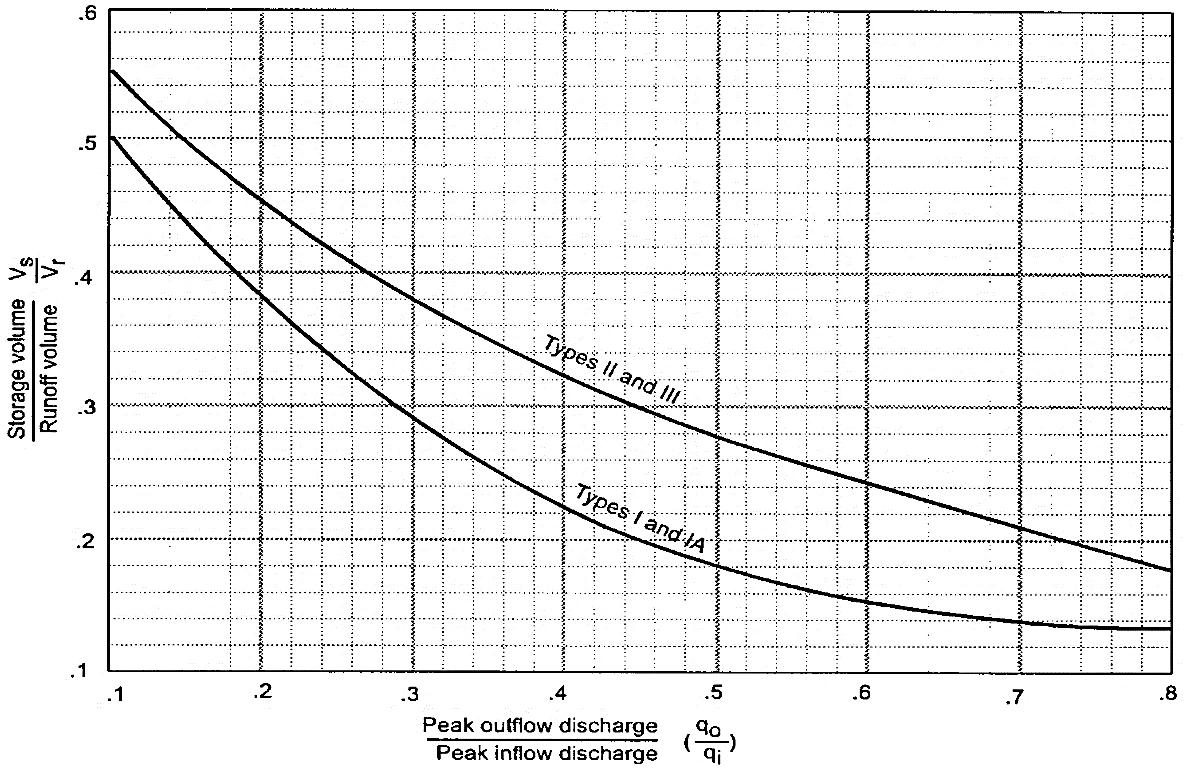
Step 9. The required storage volume (Vs) can then be calculated using Equation 3.3.1 3
Equation 3.3.1.3 �������� = ��������� �������� � �������� ���� ��������
where:
Qd = the post-development runoff depth for the design storm (inches)
A = total drainage area
Step 10. Vs must be incorporated into the SCM design, and the 1-year 24-hour storm routed through the SCM. Adjust the design accordingly. The Vs is adequate when the 1-year 24-hour design storm (or design volume as allowed by Section 3.3.1) is detained for at least 24 hours and no more than 48-hours The release period is a brim drawdown time, beginning at the time of peak storage of the CPv until the entire calculated volume drains out of the basin. For more information see Section 3.5.8 (Extended Detention Outlet Design).
Example 3.3.1.1 illustrates the estimation of CPv.
Example 3.3.1.1 Estimation of CPv
Estimate the CPv necessary for a 50-acre wooded watershed, which will be developed as follows:
Forest land - good cover (hydrologic soil group B) = 10 ac
Forest land - good cover (hydrologic soil group C) = 10 ac
Residential with 1/3 acre lots (hydrologic soil group B) = 20 ac
Industrial development (hydrological soil group C) = 10 ac
Other data include the following:
Total impervious area = 18 acres
% of pond and swamp area = 0
Step 1 Determine the rainfall depth (P) for the 1-year 24-hour design storm for development location. For this example, the 1-year, 24 hour rainfall = 2.04 inches = P
Step 2 Determine the weighted runoff coefficient as in the table below.
Step 3 Calculate Ia/P for CN= 72, Ia = 0.778 (Table 3.2.8.3) Ia/P = (0.778/2.5) = 0.31
Step 4 Calculate Qd for 1-year 24-hour storm using SCS equation Qd = (2.5-0.778)2/(2.5-0.778+5*0.778) = 0.53 inches
Step 5 Calculate Tc.
Utilizing standard methods for overland, shallow concentrated and channel flow: Tc = 0.35 hours (assumed)
Step 6 Use Tc with the ratio Ia/P to obtain the unit peak discharge, qu, from Figure 3.2.5.1 for the Type III rainfall distribution. From the figure, qu = 390 csm/in
Step 7 Estimate channel protection volume (CPv = VS) Knowing qu (1-year) = 390 csm/in from Step 6 and T (extended detention time of 24 hours), find qo/qi from Figure 3.3.1.1 qo/qi = 0.040
Step 8 Estimate storage/runoff using Equation 3.5.1.1, Vs/Vr = 0.682 - 1.43(qo/qi) + 1.64(qo/qi)2 – 0.804(qo/qi)3 Vs/Vr = 0.682 - 1.43(0.040) + 1.64(0.040)2 – 0.804(0.040)3 = 0.63
Step 9 The necessary detention volume is then calculated using Equation 3.2.8.3 CPv = Vs ≈ (Vs/Vr)*Qd*A/12 = (0.63)(0.53)(50)/12 ≈ 1.39 ac-ft
3.4 Storage Design
3.4.1
Design Standards
For many years, local governments have required detention or retention storage of stormwater to attenuate postconstruction peak discharges for purposes of drainage and flood control. Detention and retention can be provided by dry detention basins, wet basins, and stormwater wetlands.
Paraphrased detention/retention standards for Johnson City, Kingsport, Bristol TN, and Elizabethton are provided in Table 3.4.1.1, along with the document where the standards and their supporting policies are provided.
Table 3.4.1.1 Primary Storage Design Standards by Local Government
Local Government Standard or Location of Standard
Location: City of Johnson City Public Works Department Standards
Rainfall Data Source: Rainfall information contained in Technical Paper 40 (TP40), also titled Rainfall Frequency Atlas of the Eastern United States shall be used to meet the channel protection and detention/retention standards when designing detention/retention facilities
Johnson City
Kingsport, TN
Bristol
Elizabethton
Detention/Retention Standard: The post-development discharge must be less than or equal to the pre-development discharge for the 2-year through 100-year, 24-hour design storm events. Storage structures must be sized to hold the difference in the pre-development and postdevelopment runoff volumes for the 100-year storm.
Location: Article III, Division 4 of the City of Kingsport Code of Ordinances
Detention/Retention Standard: The post-development discharge must be less than or equal to the pre-development discharge for the 2-year through 100-year, 24-hour design storm events.
Location: The City of Bristol Infrastructure Design Standards
Detention/Retention Standard: The post-development discharge must be less than or equal to the pre-development discharge for the 2-year through 100-year, 24-hour design storm events.
Location: The City of Elizabethton Stormwater Guidance Manual
Detention/Retention Standard: Post-development peak discharge rates for 2 through 10-year, 24 hour rainfall events shall not exceed the peak discharge rates for existing site conditions. In the event that there are inadequate receiving facilities downgradient of the property, the postdevelopment peak discharge rate shall be controlled for the 2 through 100-year 24-hour rainfall events.
Detention and retention facilities can also be used to meet stormwater quality and channel protection standards through the addition of extended detention outlet(s). The extended time period for stormwater detention supports pollutants settling out of the water column to the bottom of the facility. The outlet also moderates the peak discharge of the 1-year storm to reduce the potential for high frequency discharges to erode streambanks downstream of the facility.
3.4.2 Storage Types and Design Configurations
The main types of storage facilities are depicted in Figure 3.4.1.1 and described after the figure.
3.4.1.1 Detention Storage Types (Adapted from ARC, 2016)
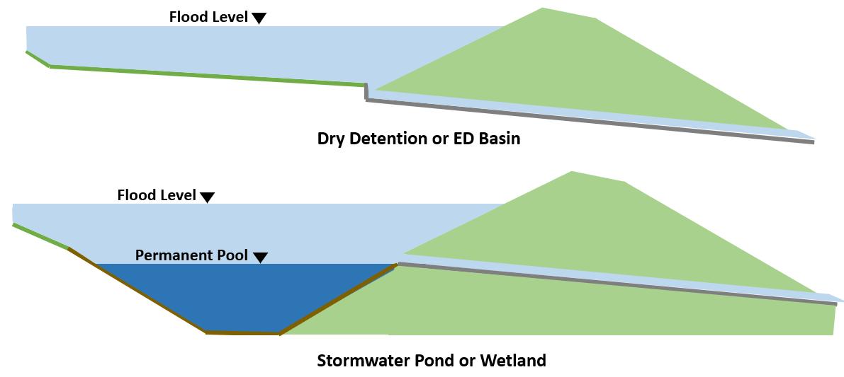
Detention storage, also called “standard or conventional detention”, is used to detain stormwater runoff from a developed property for a short period of time and release it at a specified peak discharge. Typical detention design standards require release of post-construction peak discharges that match (or are less than) pre-development peak discharges for a suite of design storm (see Figure 3.4.1.2). The storage area is designed to drain completely after the design storm(s) have passed.
3.4.1.2
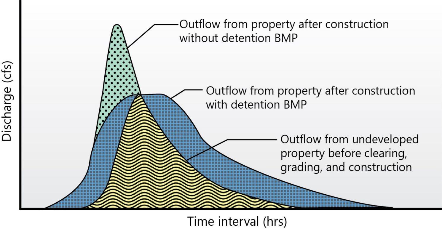
Figure
Figure
Example of Peak Flow Control by a Standard Detention Basin (Source: City of Topeka, 2021)
Extended detention (ED) storage is used to detain stormwater runoff for a longer period of time than conventional detention storage. ED storage designs typically focus on volume control, rather than designing for a specific peak discharge, and is designed to drain completely within a specified time period (usually 24 to 72 hours). ED storage is the approach employed to meet the channel protection standard (see Section 3.3), and one of the treatment mechanisms for Group 3 SCMs for stormwater quality treatment. It is not uncommon to see a “stacked” detention design where a traditional detention storage area is designed above a smaller ED storage area within the same detention basin. A multistage outlet is designed to meet both storage types. Stacked designs can be used in dry ED basins, wet basins, and stormwater wetlands. Permeable pavement systems can also be designed this way, although this is not common.
Retention storage has a permanent pool of water but can still be designed to detain and discharge water at specific rates and time periods when the permanent pool elevation is exceeded. Wet basins and stormwater wetlands are an example of retention storage. Standard dentention and/or ED storage can also be designed above retained permanent pool Group 2 SCMs, such as bioretention areas and dry swales with underdrains, detain stormwater to some degree as an ancillary outcome of their biofiltration treatment mechanisms. However, these SCMs are not typically designed for detention or ED storage purposes.
Stormwater storage can also be online or offline (see Figure 3.4.1.3). Online storage is located within the main flow path, receiving flows directly from an onsite stormwater conveyance system. Online storage can also receive flows directly from a stream, but this design configuration requires significant engineering analysis and authorization/permits from local, State, and (sometimes) Federal agencies. In contrast, offline storage receives water that is diverted from onsite conveyance system using a flow splitter or other diversion structure.
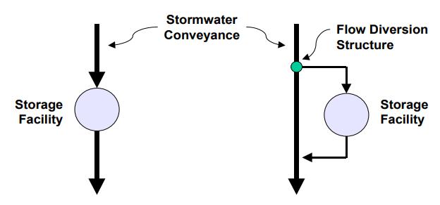
3.5 Storage Facility Outlet Structures
This section provides an overview of hydraulics and design for the most common outlet structure types for stormwater storage facilities, shown in Figure 3.5.1.1. The source of information provided in this section is the Georgia Stormwater Management Manual, 2016 Edition. The design engineer is referred to an appropriate hydraulics text for additional information on outlet structures not contained in this section.
The remainder of this page was intentionally left blank.
Figure 3.4.1.3 Online and Offline Storage (Source: ARC, 2016)
Each outlet type has a different design purpose and application.
WQv and CPv flows are normally handled with smaller, more protected outlet structures such as reverse slope pipes, hooded orifices, orifices located within screened pipes or risers, perforated plates or risers, and V-notch weirs.
The larger flood and drainage control flows are typically handled through a riser with different sized openings, through an overflow at the top of a riser (drop inlet structure), or a flow over a broad crested weir or spillway through the embankment. Overflow weirs can also be of different heights and configurations to handle control of multiple design flows.
3.5.1 Orifices
Figure 3.5.1.1 Common Outlet Types for Storage Facilities (Source: ARC, 2016)
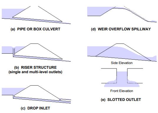
An orifice is a circular or rectangular opening of a prescribed shape and size. The flow rate depends on the height of the water above the opening and the size and edge treatment of the orifice
For a single orifice, the discharge is determined using the standard orifice equation (Equation 3.5.1.1). See also Figure 3.5.1.1.
Equation 3.5.1.1
���� = ��������(������������)���� ���� where:
Q = orifice flow rate (or discharge) (cfs)
C = discharge coefficient (see Table 3.4.1.1)
A = cross-section area of orifice or pipe (ft2)
g = acceleration due to gravity (32.2 ft/s2)
D = diameter of orifice or pipe (ft)
H = effective head on the orifice, from its center to the upstream (headwater) surface elevation (ft); if the orifice is submerged, H is the difference in the headwater and tailwater surface elevations (see Figure 3.5.1.1)
Orifice
Table 3.5.1.1 Orifice Discharge Coefficient (C)
Figure 3.5.1.1. Orifice Parameters (Source: ARC, 2016)
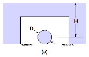
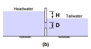
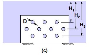
If the orifice discharges as a free outfall, then the effective head is measured from the center of the orifice to the upstream (headwater) surface elevation. If the orifice discharge is submerged, then the effective head is the difference in elevation of the headwater and tailwater surfaces as shown in Figure 3.5.1.1 (b).
When multiple orifices in a perforated orifice plate are used but with different effective heads (H), as shown in Figure 3.5.1.1.c, sum the flow through the individual orifices for the combined flow. If the orifices are the same size and have the same discharge coefficient (C) and effective head (H), the total flow can be determined my multiplying Q for a single orifice by the number of openings. Figure 3.5.1.2 is a schematic of an orifice plate outlet structure for a wet ED basin. The design pool elevations and flow control mechanisms are shown.
For rectangular slots, the slot height is normally 2-inches with variable width. Only one column of rectangular slots is allowed.
Figure 3.5.1.2 Schematic of Outlet Structure Design with an Orifice Plate
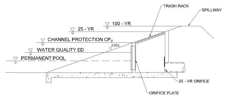
Table 3.5.1.2 presents the standardized dimensions for orifice plates with circular perforations.
Table 3.5.1.2 Standardized Dimensions for Orifice Plates with Circular Perforations (Source: UDFCD, 2013)
3.5.2 Perforated Risers
A perforated riser is shown in Figure 3.5.2.1 In this type of outlet structure, an orifice plate at the bottom of the riser, or in the outlet pipe just downstream from the elbow at the bottom of the riser, controls the flow. It is important that the perforations in the riser convey more flow than the orifice plate so as not to become the control. Use the shortcut formula in Equation 3.5.2.1 to estimate the total flow capacity of the perforated section.
Equation 3.5.2.1 ���� = �������� ������������ ������������ ����������������������
where:
Q = discharge (cfs)
Cp = discharge coefficient (normally 0.61)
Ap = cross-sectional area of all holes (ft2)
Hs = distance from S/2 below the lowest row of holes to S/2 above the top row (see Figure 3.5.2.1)
H = elevation head differential (ft)
3.5.3 Extended Detention Outlet Design (for WQv and CPv)
Discharge pipes or culverts are often used as outlet structures for storage facilities. The design of these pipes can be for single or multi-stage discharges. A reverse slope underwater pipe is often used for WQv and CPv outlets.
3.5.2.1 Perforated Riser (Source: ARC, 2016)

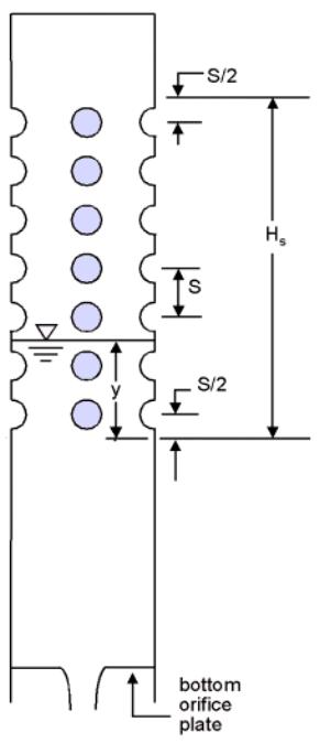
Pipes smaller than 12 inches in diameter may be analyzed as a submerged orifice as long as H/D is greater than 1.5. Note: For low flow conditions when the flow reaches and begins to overflow the pipe, weir flow controls (see Subsection 3.4.2.6). As the stage increases the flow will transition to orifice flow. Pipes greater than 12 inches in diameter should be analyzed as a discharge pipe with headwater and tailwater effects considered. The outlet hydraulics for pipe flow can be determined from outlet control culvert design nomographs and procedures.
Equation 3.5.3.1 is a general pipe flow equation that is derived through the use of the Bernoulli and continuity principles.
Equation 3.5.3.1 ���� = ���� � ������������ ���� + �������� + �������� ����� ����. ���� where:
Q = discharge (cfs)
a = pipe cross-sectional area (ft2)
g = acceleration of gravity (32.2 ft/s)
H = elevation head differential (ft)
km = coefficient of minor losses (use 1.0)
kp = pipe friction coefficient = 5087n2/D4/3
L = pipe length (ft)
3.5.4 Sharp-Crested Weirs
A sharp-crested weir has an overflow portion with a sharp, thin, leading (upstream) edge such that water springs clear of the weir as it flows over it. If the sides of the weir also cause the flow of water to contract, the weir is called an end-
Figure
contracted, sharp-crested weir. Weir configurations with no end contractions and with two end contractions are shown in Figures 3.5.4.1(a) and (b). The figure also shows dimension parameters used in the discharge equations.
Equation 3.5.4.1 is the discharge equation for a sharp-crested weir without end-contractions (Chow, 1959)
Equation 3.5.4.1
where:
Q = discharge (cfs)
H = head above weir crest excluding velocity head (ft)
Hc = height of weir crest above channel bottom (ft)
L = horizontal weir length (ft)
3.5.4.1

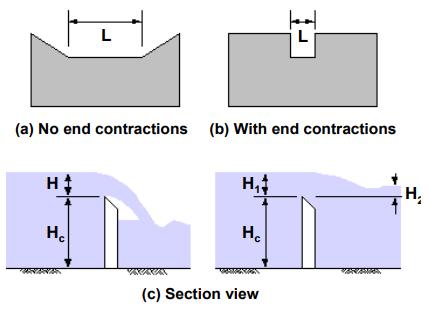
Equation 3.5.4.2 is the discharge equation for a sharp-crested weir with two end contractions (Chow, 1959). The parameters are the same as defined for Equation 3.5.4.1
Equation 3.5.4.2
A sharp-crested weir will be affected by submergence when the tailwater rises above the weir crest elevation, reducing the discharge over the weir. Equation 3.5.4.3 is the discharge equation for a submerged sharp-crested weir (Brater and King, 1976).
Equation 3.5.4.3
where:
Q = submerged flow (cfs)
Qf = free flow (cfs)
H1 = upstream head above crest (ft)
H2 = downstream head above crest (ft)
3.5.5 Broad-Crested Weirs
A weir in the form of a relatively long raised channel control crest section is a broad-crested weir (see Figure 3.5.5.1). The flow control section can have different shapes, such as triangular or circular. True broad-crested weir flow occurs when upstream head above the crest is between the limits of about 1/20 and 1/2 the crest length in the direction of flow. For example, a thick wall or a flat stop log can act like a sharp-crested weir when the approach head is large enough that the flow springs from the upstream corner. If upstream head is small enough relative to the top profile length, the stop log can act like a broad-crested weir (USBR, 1997).
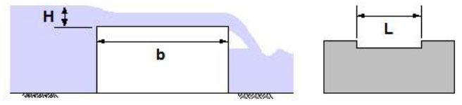
Figure 3.5.5.1 Broad-Crested Weir (Source: ARC, 2016)
Figure
Sharp-Crested Weirs (Source: ARC, 2016)
Equation 3.5.5.1 is the discharge equation for a sharp-crested weir without end-contractions (Brater and King, 1976).
Equation 3.5.5.1 ���� = ���������������� ���� where:
Q = discharge (cfs)
C = broad-crested weir coefficient (see Table 3.5.1.2)
L = weir length perpendicular to flow (ft)
H = head above weir crest (see Figure 3.5.5.1)
Table 3.5.5.1 Broad-Crested Weir Coefficient (C) Values (Source: Brater and King, 1976)
*Measured at least 2.5H upstream of the weir.
3.5.6 V-Notch Weirs
The configuration of a v-notch weir is obvious from its name (see Figure 3.5.6.1). Equation 3.5.6.1 is the discharge equation for a v-notch weir (Brater and King, 1976).
Equation 3.5.6.1 ���� = ���� ���� ������������ �Ɵ ���� � �������� ���� where:
Q = discharge (cfs)
Ɵ = angle of v-notch (degrees)
H = head above weir crest (see Figure 3.5.6.1)
3.5.6.1 V-Notch Weir (Source: ARC, 2016)
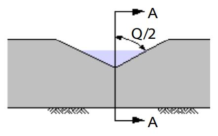
3.5.7 Proportional Weirs
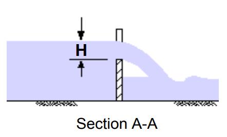
Equations 3.5.7.1 and 3.5.7.2 are the design equations for proportional weirs (Sandvik, 1985).
Equation 3.5.7.1
Equation 3.5.7.2
where:
Q = discharge (cfs)
See Figure 3.5.7.1 for dimensions a, b, H, x, and y)
3.5.8 Extended Detention Outlets
Figure 3.5.7.1 Proportional Weir Dimensions (Source: ARC, 2016)

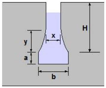
This section and its procedures are taken from the Georgia Stormwater Management Manual, 2016 Edition, which credits the procedures to the Virginia Stormwater Management Handbook, 1999.
Extended detention outlet design is required for SCMs that use extended detention storage for stormwater quality (WQv) and/or channel protection (CPv) control. SCMs that will commonly implement extended detention are listed below.
Standard dry detention basins
Dry ED basins
Underground detention basins (does not control the WQv, CPv only)
Permeable pavement systems
Stormwater wetlands
Submerged stormwater wetlands
Water quality (wet) basins
Local government requirements for flood control (i.e., peak discharge control) require selection of an outlet (or series of outlets) that will limit the post-development peak flow for a design storm to a predetermined maximum (usually the predevelopment peak flow). The outlet design is easily determined, and routing procedures used to determine if flood control design standards are met. However, the outlet control hydraulics for extended detention is difference, since volume and the time required for water to exit the storage facility muse be considered
In an SCM that employs extended detention, the storage volume is detained and released over a minimum of 24 hours and maximum of 48 hours. The release period is a brim drawdown time, beginning at the time of peak storage of the water quality volume until the entire calculated volume drains out of the basin. This assumes that the brim volume is present in the basin prior to any discharge. In reality, however, water is flowing out of the basin prior to the full or brim volume being reached. Therefore, the extended detention outlet can be sized using either of the following methods
Figure
Experience shows that a 48-hour drawdown requirement can yield an unreasonably small extended detention orifice diameter for small drainage areas. Small orifices and discharge pipes can easily be buried by inflows of sediment and debris, and therefore are difficult to maintain. Use the minimum 24-hour drawdown period for orifice calculations if 48hours yields unreasonable results. As well, the SCM design specification in Chapter 5 may include minimum orifice diameter requirements.
Approach 1 - Maximum Hydraulic Head With Routing
This method uses the maximum hydraulic head associated with the storage volume and maximum flow. The orifice size needed to achieve the required drawdown time is determined, then the volume is routed through the basin to verify the actual storage volume used and the drawdown time.
A wet ED pond sized for the required water quality volume will be used here to illustrate the sizing procedure for an extended-detention orifice. Given the following information, calculate the required orifice size for stormwater water quality (WQv) design.
Given: Water Quality Volume (WQv) = 0.76 ac ft = 33,106 ft3
Maximum Hydraulic Head (Hmax) = 5.0 ft (from stage vs. storage data)
Since this is a Group 3 SCM that will control the entire WQv for its drainage area, the drawdown (extended detention) requirement is a minimum of 24 to a maximum of 48 hours. Per the channel protection (CPv) standard established in Section 3.3.1, achievement of the stormwater quality (WQv) standard will also achieve the CPv standard. Thus, a second outlet for CPv control is unnecessary.
Step 1. Determine the maximum discharge resulting from the 48-hour drawdown requirement. It is calculated by dividing the WQv by the required time to find the average discharge, and then multiplying by two to obtain the maximum discharge.
Qavg = 33,106 ft3/(48 hr)(3,600 s/hr) = 0.19 cfs
Qmax = 2 * Qavg = 2 * 0.19 = 0.38 cfs
Step 2. Determine the required orifice diameter using the Equation 3.5.1.1 (the orifice equation) and Qmax and Hmax:
Q = CA(2gH)0.5, or A = Q / C(2gH)0.5
A = 0.38 cfs / 0.6[(2)(32.2 ft/s)(5.0 ft)]0.5 = 0.035 ft3
This result makes it clear that the orifice and pipe diameter will be unreasonably small given the 48-hour drawdown requirement. Steps 1 and 2 are recalculated using a 24-hour drawdown requirement, yielding A = 0.071 ft3. Proceed to Step 3 with the 24-hour drawdown results.
Step 3: Determine pipe diameter from
A = 3.14r2 = 3.14d2/4, then d = (4A/3.14)0.5
D = [4(0.071 ft3)/3.14]0.5 = 0.30 ft = 3.61 in
Use a 3.6-inch diameter water quality orifice.
Routing the water quality volume of 0.76 ac ft through the 3.6-inch water quality orifice will allow the designer to verify the drawdown time, as well as the maximum hydraulic head elevation. The routing effect will result in the actual drawdown time being less than the calculated 24 hours. Judgment should be used to determine whether the orifice size should be reduced to achieve the required 24 hours or if the actual time achieved will provide adequate pollutant removal.
Approach 2 - Average Hydraulic Head and Average Discharge
Again, a wet ED pond sized for the required water quality volume will be used here to illustrate this approach for sizing an extended-detention orifice.
Given: Water Quality Volume (WQv) = 0.76 ac ft = 33,106 ft3
Maximum Hydraulic Head (Hmax) = 5.0 ft (from stage vs. storage data)
Since this is a Group 3 SCM that will control the entire WQv for its drainage area, the drawdown (extended detention) requirement is a minimum of 24 to a maximum of 48 hours. Per the channel protection (CPv) standard established in Section 3.3.1, achievement of the stormwater quality (WQv) standard will also achieve the CPv standard. Thus, a second outlet for CPv control is unnecessary.
In this example, our experience in designing extended detention outlets tells us to size using a 24-hour drawdown period to avoid an overly small orifice diameter.
Step 1. Determine the average release rate to release the WQV over a 24-hour time period.
Qavg = 33,106 ft3/(24 hr)(3,600 s/hr) = 0.38 cfs
Step 2. Determine the required orifice diameter using the Equation 3.5.1.1 (the orifice equation) and the average head on the orifice (Havg = 2.5 feet):
Q = CA(2gH)0.5, or A = Q / C(2gH)0.5
A = 0.38 cfs / 0.6[(2)(32.2 ft/s)(2.5 ft)]0.5 = 0.05 ft3
Step 3: Determine pipe diameter from
A = 3.14r2 = 3.14d2/4, then d = (4A/3.14)0.5
D = [4(0.05 ft3)/3.14]0.5 = 0.252 ft = 3.03 in
Use a 3-inch diameter water quality orifice.
3.5.9 Combination Outlet Structures/Multi-Stage Outlets
Combinations of orifices , weirs, and pipes can be used to provide multi-stage outlet control for different control volumes and peak discharges within a storage facility. In general, there are two types of combination outlets: shared outlet control structures and separate outlet control structures. Shared outlet control is typically a number of individual outlet orifices, weirs, or drops at different elevations on a riser pipe or box which all discharge to a common larger conduit or pipe. The multi-stage plate in Figure 3.5.1.2 is an example of shared outlet control.
Separate outlet controls are less common. They may consist of several pipe or culvert outlets at different levels in the storage facility that are either discharged separately or combined to discharge at a single location.
A combination outlet such as a multiple orifice plate system or multi-stage riser is often used to provide adequate hydraulic outlet controls for the different design requirements (e.g., WQv, CPv, and flood control). They are most commonly used in detention basins (all configurations) and stormwater wetlands (all configurations). Separate openings or devices at different elevations are used to control the rate of discharge from a facility during multiple design storms. Figure 3.5.9.1 shows an example of a multi-stage riser for a wet extended detention basin.
A design professional may be creative to provide the most economical and hydraulically efficient outlet design possible in designing a multi-stage outlet. Many iterative routings are usually required to arrive at a minimum structure size and storage volume that provides proper control. The stage-discharge table or rating curve is a composite of the different outlets that are used for different elevations within the multi-stage riser (see Figure 3.5.9.2).
3.5.9.1 Schematic of a Multi-Stage Riser (Source: ARC, 2016)
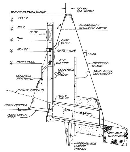
Design Procedure
Figure 3.5.9.2 Composite Stage-Discharge Curve (Source: ARC, 2016)
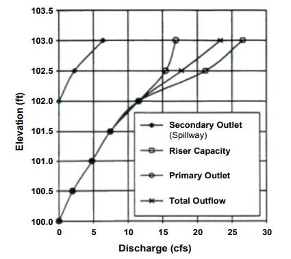
The steps for design of a multi-stage outlet are below. Note: If an SCM will not control one or more of the required storage volumes, then that step in the procedure is skipped.
Step 1. Determine Stormwater Volumes Determine the WQv and/or CPv, and the flood control volumes needed for peak discharge control of the required design storms. The latter is provided in Section 3.4 (Storage Design) for each local government.
Step 2. Develop Stage-Storage Curve. Develop the stage-storage curve for the SCM using the site geometry and topography. Sufficient storage must be provided for the control volumes determined in Step 1.
Step 3. Design WQv and/or CPv Outlets. If the design is for a Group 3 SCM that will provide extended detention, design the extended detention orifice for the WQv (see Section 3.2 for WQv determination and Section 3.5.8 for extended detention outlet sizing). The WQv orifice alone will address both the WQv and CPv design standards (see the channel protection design standard in Section 3.3.1). The total stage-discharge curve at this point will be only for the WQv orifice.
If the design is for a storage facility that will provide only CPv control without WQv control, design the extended detention orifice for the CPv (see Section 3.3 for CPv determination and Section 3.5.8 for extended detention outlet sizing). The total stage-discharge curve at this point will be only for the CPv orifice.
If the design is for a storage facility that will provide both WQv and CPv control in a stacked configuration (i.e., the WQv and CPv will be controlled separately) design both orifices as described above. Then, the total stage-discharge curve at this point will include both the WQv orifice and CPv orifice.
Figure
Regardless of WQv/CPv orifice configuration, if the SCM will be designed to have a permanent pool, a portion of the storage volume for WQv (or CPv, or both) will be above the elevation of the permanent pool. The outlet can be protected using either a reverse slope pipe, a hooded protection device, or another acceptable method. (see Section 3.6).
Step 4. Design Flood Control Outlets The flood control volumes are added above the WQv/CPv storage. Establish the maximum water surface elevation for each design storm using the stage-storage curve and subtract the WQv (or CPv, or both) elevation to find the maximum head for the design storm. Select an outlet type and calculate the initial size and geometry based on maintaining the pre-development peak discharge rate (Qp) for the design storm. Develop a stage-discharge curve for the combined sent of outlets (WQv, CPv (if separate), and Qp).
Step 4 is repeated for peak flow attenuation of all required design storms.
Step 5. Check Outlet Structure Performance. Perform a hydraulic analysis of the multi-stage outlet structure using reservoir routing to ensure that all outlets will function as designed. Several iterations may be required to calibrate and optimize the hydraulics and outlets that are used. Also, the structure should operate without excessive surging, noise, vibration, or vortex action at any stage. This usually requires that the structure have a larger cross-sectional area than the outlet conduit.
The hydraulic analysis of the design must consider the hydraulic changes that will occur as depth of storage changes for the different design storms. As the water passes over the rim of a riser, the riser acts as a weir. However, when the water surface reaches a certain height over the rim of a riser, the riser will begin to act as a submerged orifice. Flow diagrams depicting these situations are provided in Figure 3.5.9.3 The designer must compute the elevation at which this transition from riser weir flow control to riser orifice flow control takes place for an outlet where this change in hydraulic conditions will change. Also note in Figure 3.5.9.3 that as the elevation of the water increases further, the control can change from barrel inlet flow control to barrel pipe flow control.
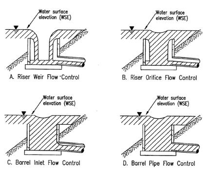
Figure 3.5.9.3 Riser Flow Diagrams (Source: VDCR, 1999)
Figure 3.5.9.4 shows another condition where weir flow can change to orifice flow, which must be considered in the hydraulics of the rating curve as different design conditions results in changing water surface elevations.
Figure 3.5.9.4 Weir and Orifice Flow (Source: VDCR,
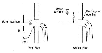
Step 6. Size the Emergency Spillway. An emergency spillway is required for all surface detention, retention, and wetland storage areas It provides a degree of safety to prevent overtopping of an embankment if the primary outlet structure or principal spillway becomes clogged or otherwise fails. See Section 3.5.10 for guidance on emergency spillway design. Route the 100-year storm through the outlet devices and emergency spillway to ensure the hydraulics of the storage area will operate as designed.
Step 7. Design the Outlet Protection Design necessary outlet protection and energy dissipation devices to avoid outlet clogging and erosion problems downstream from the outlet and spillway. See Section 3.6 (Outlet Protection) for more information.
Step 8. Perform Buoyancy Calculations. Floatation of the outlet structure and its components will occur when its weight is less than or equal to the buoyant force exerted by the water. Thus, confirmation that the outlet structure will not float is required. Perform buoyance calculations for the structure, including its footing.
Step 9. Provide Seepage Control. Seepage control should be provided for the outflow pipe or culvert through an embankment using anti-seep collars
3.5.10 Emergency Spillways
Emergency spillway designs are open channels, usually trapezoidal in cross section, and consist of an inlet channel, a control section, and an exit channel (see Figure 3.5.10.1). The emergency spillway is proportioned to pass flows in excess of the design flood (typically the 100-year flood or greater) without allowing excessive velocities and without overtopping of the embankment. Flow in the emergency spillway is open channel. Normally, it is assumed that critical depth occurs at the control section.
NRCS (NRCS TR-55) manuals provide guidance for the selection of emergency spillway characteristics for different soil conditions and different types of vegetation. The selection of degree of retardance for a given spillway depends on the vegetation. Knowing the retardance factor and the estimated discharge rate, the emergency spillway bottom width can be determined. For erosion protection during the first year, assume minimum retardance.
Both the inlet and exit channels should have a straight alignment and grade. Spillway side slopes should be no steeper the 3:1 horizontal to vertical.
The most common type of emergency spillway used is a broad-crested overflow weir cut through original ground next to the embankment. The transverse cross section of the weir cut is typically trapezoidal in shape for ease of construction. Such an excavated emergency spillway is illustrated in Figure 3.5.10.1.
Figure 3.5.10.1 Emergency Spillway (Source: VDCR, 1999)
Note: Neither the location nor the alignment of the level section has to coincide with the centerline of embankment.

DEFINITION OF TERMS:
Hp - Depth of water in impoundment above crest
L - Length of level section
b - Bottom width of spillway
So - Slope of exit channel
Sc - Critical slope
Se - Slope of inlet channel
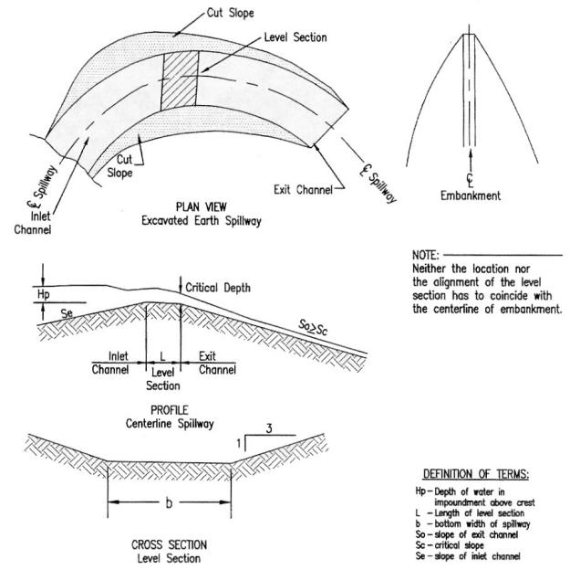
3.6 Outlet Protection
3.6.1
Extended Detention Outlet Protection

Extended detention outlets are typically small (approximately 3-inches or so in diameter) and can easily clog, preventing the SCM from meeting its design purpose(s) and potentially causing adverse impacts. Therefore, extended detention orifices need to be adequately protected from clogging. There are a number of different anti-clogging designs, all shown in Figure 3.6.1.1 The designs are described below.
Figure 3.6.1.1
Types of Extended Detention Outlets
(Source: ARC, 2016)
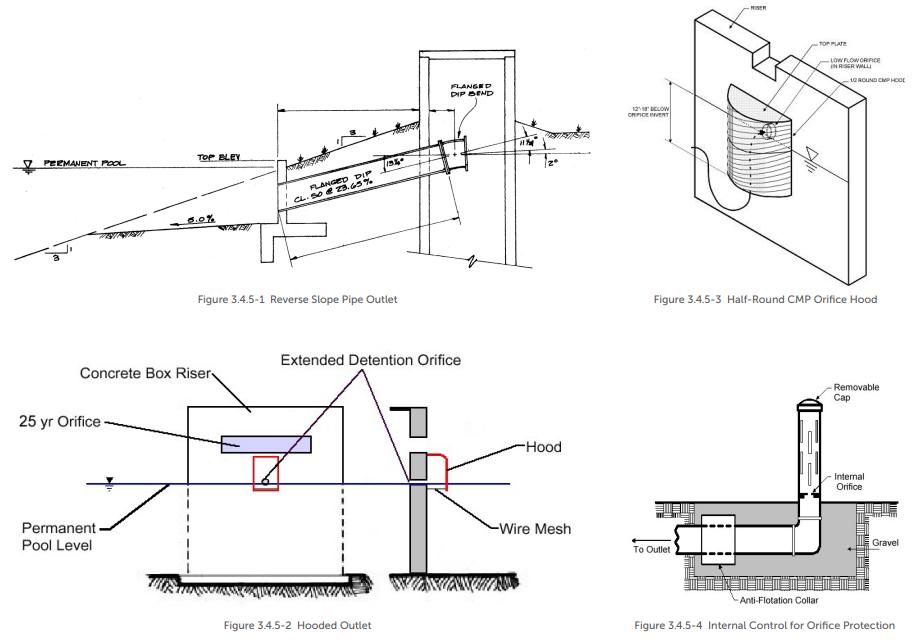
A reverse slope pipe can be attached to the riser in a stormwater basin or wetland with a permanent pool. The inlet is submerged 1 foot below the elevation of the permanent pool to prevent floatables from clogging the pipe and to avoid discharging warmer water at the surface of the pond.
The use of a hooded outlet for a stormwater pond or wetland with a permanent pool.
Internal orifice protection through the use of an over-perforated vertical standpipe with ½-inch orifices or slots that are protected by wirecloth and a stone filtering jacket.
Internal orifice protection through the use of adjustable gate valves to achieve an equivalent orifice diameter.
3.6.2
Trash Racks and Safety Grates
The susceptibility of larger inlets to clogging by debris and trash needs to be considered when estimating their hydraulic capacities. In most instances trash racks will be needed. Trash racks and safety grates are a critical element of outlet structure design and serve several important functions.
Keeping debris away from the entrance to the outlet works where they will not clog the critical portions of the structure
Capturing debris in such a way that relatively easy removal is possible
(a) Reverse Slope Pipe Outlet
(b) Hooded Outlet
(d) Internal Control for Orifice Protection
(c) Half-Round CMP Orifice Hood
Ensuring that people and large animals are kept out of confined conveyance and outlet areas
Providing a safety system that prevents anyone from being drawn into the outlet and allows them to climb to safety
When designed properly, trash racks serve these purposes without interfering significantly with the hydraulic capacity of the outlet (or inlet in the case of conveyance structures) (ASCE, 1985; Allred-Coonrod, 1991). The location and size of the trash rack depends on a number of factors, including head losses through the rack, structural convenience, safety, and size of outlet. Well-designed trash racks can also have an aesthetically pleasing appearance.
An example of trash racks used on a riser outlet structure is shown in Figure 3.6.2.1. Trash rack design is based on the effective opening of the trash rack compared to the orifice, or outlet size. The outlet size should be the controlling or smaller open area, when compared to the effective open area of the trash rack.
The inclined vertical bar rack is most effective for lower stage outlets. Debris will ride up the trash rack as water levels rise. This design also allows for removal of accumulated debris with a rake while standing on top of the structure.
Trash racks must be large enough such that partial plugging will not adversely restrict flows reaching the control outlet. There are no universal guidelines for the design of trash racks to protect detention basin outlets, although a commonly used “rule-of-thumb” is to have the trash rack area at least ten times larger than the control outlet orifice.

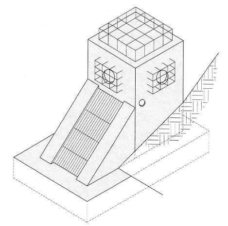
The surface area of all trash racks should be maximized, and the trash racks should be located a suitable distance from the protected outlet to avoid interference with the hydraulic capacity of the outlet. The spacing of trash rack bars must be proportioned to the size of the smallest outlet protected. However, where a small orifice is provided, a separate trash rack for that outlet should be used, so that a simpler, sturdier trash rack with more widely spaced members can be used for the other outlets. Spacing of the rack bars should be wide enough to avoid interference, but close enough to provide the level of clogging protection required.
To facilitate removal of accumulated debris and sediment from around the outlet structure, the racks should have hinged connections. If the rack is bolted or set in concrete, it will preclude removal of accumulated material and will eventually adversely affect the outlet hydraulics.
Since sediment will tend to accumulate around the lowest stage outlet, the inside of the outlet structure for a dry basin should be depressed below the ground level to minimize clogging due to sedimentation. Depressing the outlet bottom to a depth below the ground surface at least equal to the diameter of the outlet is recommended.
Figure 3.6.2.1 Example of Various Trash Racks Used on a Riser Outlet Structure (Source: VDCR, 1999)
Trash racks at entrances to pipes and conduits should be sloped at about 3H:1V to 5H:1V to allow trash to slide up the rack with flow pressure and rising water level the slower the approach flow, the flatter the angle. Rack opening rules-ofthumb are found in literature. Figure 3.6.2.2 gives opening estimates based on outlet diameter (UDFCD, 1992). Judgment should be used in that an area with higher debris (e.g., a wooded area) may require more opening space.
The bar opening space for small pipes should be less than the pipe diameter. For larger diameter pipes, openings should be 6 inches or less. Collapsible racks have been used in some places if clogging becomes excessive or a person becomes pinned to the rack.
Alternately, debris for culvert openings can be caught upstream from the opening by using pipes placed in the ground or a chain safety net (USBR, 1978; UDFCD, 1992). Racks can be hinged on top to allow for easy opening and cleaning.
The control for the outlet should not shift to the grate, nor should the grate cause the headwater to rise above planned levels. Therefore, head losses through the grate should be calculated. A number of empirical loss equations exist though many have difficult to estimate variables. Two will be given to allow for comparison.
(Source: UDCFD, 1992)
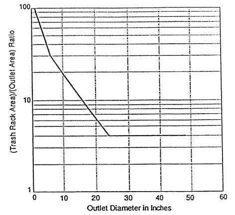
Metcalf & Eddy (1972) give Equation 3.6.2.1 (based on German experiments) for losses. Grate openings should be calculated assuming a certain percentage blockage as a worst case to determine losses and upstream head. Often 40 to 50% is chosen as a working assumption.
where:
Hg = head loss through grate (feet)
Kg1 = bar shape factor
2.42 for sharp edged rectangular
1.83 for rectangular bars with semicircular upstream face
1.79 for circular bars
1.67 for rectangular bars with semi-circular up and downstream faces
w = maximum cross-sectional bar width facing the flow (inches)
X = minimum clear spacing between bars (inches)
Vu = approach velocity (ft/s)
Ɵg = angle for the grate with respect to the horizontal (degrees)
The Corps of Engineers (HDC, 1988) developed curves for trash racks based on similar and additional tests. These curves are for vertical racks but presumably they can be adjusted, in a manner similar to the previous equation, through multiplication by the sine of the angle of the grate with respect to the horizontal. The resulting Equation 3.6.2.2 is below.
Figure 3.6.2.2 Minimum Rack Size vs. Outlet Diameter
Equation 3.6.2.2 �������� = ������������ �������� ���� �������� where:
Kg2 is defined from a series of fit curves as follows:
Sharp-edged rectangular (length/thickness = 10); so, Kg2 = 0.00158 - 0.03217Ar + 7.1786Ar2
Sharp-edged rectangular (length/thickness = 5); so, Kg2 = -0.00731 + 0.69453Ar + 7.0856Ar2
Sharp-edged rectangular (length/thickness = 10.9); so, Kg2 = -0.00101 + 0.02520Ar + 6.0000Ar2
Circular cross section; so Kg2 = 0.00866 + 0.13589Ar + 6.0357Ar2
Ar is the ratio of the area of the bars to the area of the grate section
3.7 Downstream Impact Analysis
3.7.1
Background
Local government stormwater design criteria require peak discharge control at the outlet of a site for a suite of design storms (see Section 3.4). Typically, peak discharge control is achieved through construction of one or more on-site detention basins However, peak discharge control may actually exacerbate flooding problems downstream of the site. Master plans have shown that a development site’s location within a watershed may preclude the requirement for overbank flood control from a particular site. It is for this reason that most local governments will waive the requirement for peak discharge control for developments with direct discharge to a local stream or located in a downstream portion of a watershed.
A major reason for negative impacts due to stormwater detention basins involves the timing of the peak discharge from the site in relation to the peak discharges in the receiving stream and/or its tributaries. If detention structures are indiscriminately placed in a watershed without consideration of the relative timing of downstream peak discharges, the structural control may actually increase the peak discharge downstream. An example of this situation is presented in Figure 3.7.1.1, which shows a comparison of the total downstream flow on a receiving stream (after development) with and without detention controls. In Figure 3.7.1.1, the smaller dashed-dot and solid lines denote the runoff hydrograph for a development site with and without detention, respectively. These runoff hydrographs will combine with a larger runoff hydrograph of the receiving stream (not shown). The combined discharges from the site and receiving stream are shown in the larger solid and dashed lines.
Figure 3.7.1.1 conveys a possible consequence of detention. The post-development flow from the site is reduced as required by flood protection design criteria to result in the detained flow (the smaller dashed-dot hydrograph). However, the timing of the peak discharge for the detained post-development flow, while reduced in magnitude, corresponds more closely with the timing of the peak discharge of the receiving stream (not shown) than the peak discharge of the post-
development flow that was not detained. Therefore, the combination of the detained flow with the flow in the receiving stream is actually higher than would occur if no detention were required, as shown in the larger dashed hydrograph. Hence, there is a peak flow increase that is caused by detention.
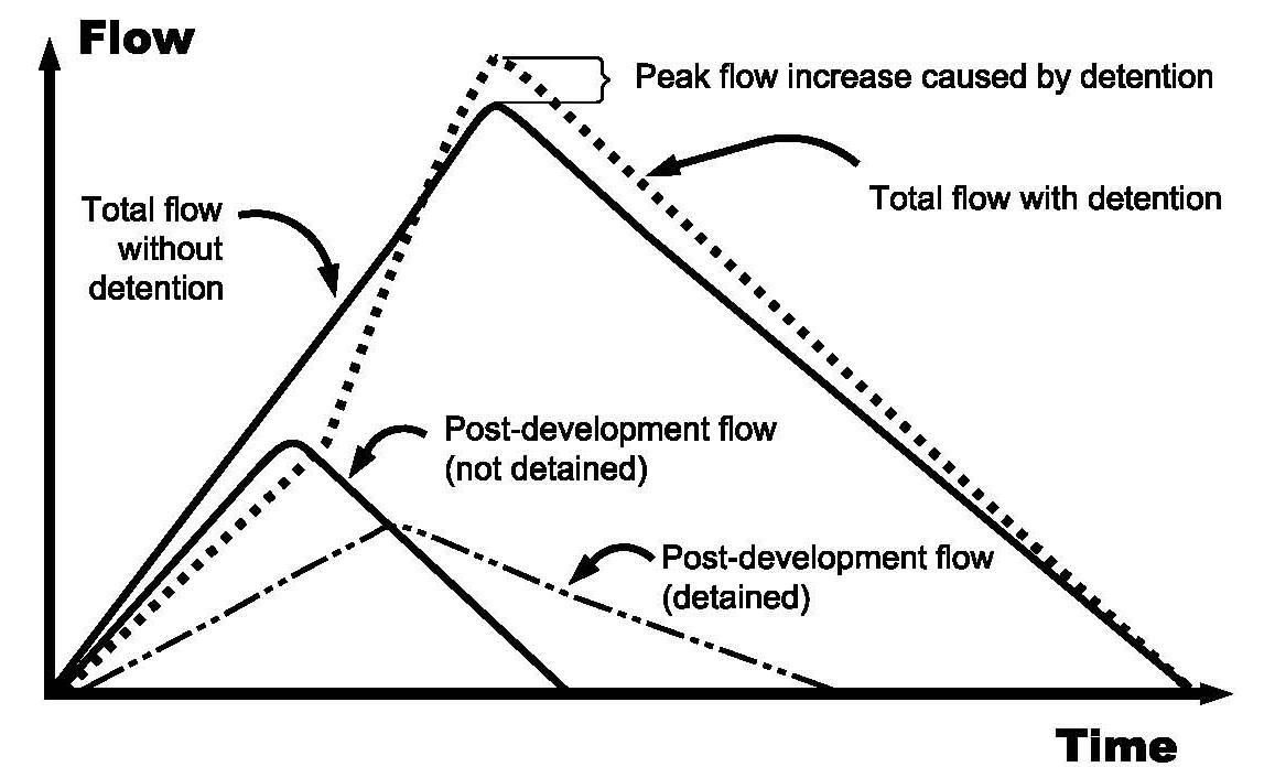
Poor peak discharge timing can have an even greater impact when one considers all the developments located in a watershed and the cumulative effects of increases in stormwater volume and the duration of high-volume runoff in the channel, as well as peak discharge timing. Even if peak discharges are handled effectively at the site level and immediately downstream, the longer duration of higher flows due to the increased volume from many developments located on or near a stream may combine with downstream tributaries and receiving streams to dramatically increase the downstream peak flows.
Figure 3.7.1.2 illustrates this concept. The figure shows the pre- and post-development hydrographs at the confluence of two tributaries. Development occurs, meets the local flood protection criteria (i.e., the post-development peak flow is equal to the pre-development peak flow at the outlet from the site), and discharges to Tributary 1. When the postdevelopment detained flow from Tributary 1 combines with the first downstream tributary (Tributary 2), it causes a peak flow increase when compared to the pre-development combined flow. This is due to the increased volume and timing of runoff from Tributary 1, relative to the peak flow and timing in Tributary 2. In this case, the detention volumes on Tributary 1 would have to have been increased to account for the downstream timing of the combined hydrographs to mitigate the impact of the increased runoff volume.
3.7.1.2
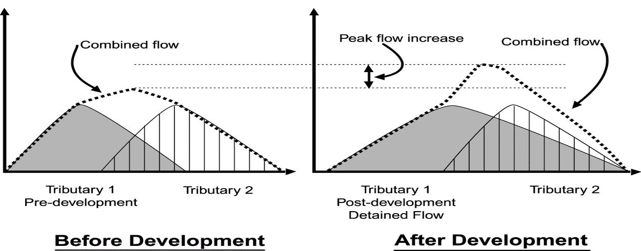
Figure
Potential Effect of Cumulative Detection Basins
Figure 3.7.1.1 Potential Effect of On-Site Detention on Receiving Streams
Potential problems such as those described above are common but can be avoided through the use of a stormwater master plan and/or downstream analysis of the effects of a planned development. Studies have shown that if a developer is required to assess the impacts of a development downstream to the point where the developed property is 10% of the total drainage area, and there are no adverse impacts (i.e., stream peak discharge increases), then there is assurance that there will not be significant increases in flooding problems further downstream. For example, for a 10-acre site, the assessment would have to take place down to a point where the total accumulated drainage area is 100 acres.
While this assessment does require some additional labor on the part of the design engineer, it allows smart stormwater management within a watershed. The assessment provides the developer, the local jurisdiction and downstream property owners with a better understanding (and corresponding documentation) of the potential downstream impacts of development. In turn, this information identifies those developments for which waivers or reductions in the flood protection requirements may prove beneficial.
3.7.2 Minimum Standards and General Policies
Policies pertaining to the downstream impact analysis, if required by the local jurisdiction, are listed below.
When required, a downstream impact analysis shall be performed for the 25-year, 24-hour design storm. Peak discharges shall be determined for the pre-development and post-development conditions. The post-development condition analysis shall include the effect of any SCM included in the post-development design for flood control purposes (i.e., standard and ED dry detentions basins, wet basins, stormwater wetlands, underground detention, submerged gravel wetlands).
Peak flows must be developed and compared at the outfall(s) of the site, and at each downstream tributary junction and each public or major private downstream stormwater conveyance structure to the point(s) in the stormwater system where the area of the portion of the site draining into the system is less than or equal to 10% of the total drainage area above that point.
If the downstream impact analysis shows that the post-development design causes an increase in peak discharges at any point in the downstream analysis area, downstream flood protection shall be provided such that the calculated peak discharges for the locally specified storm events after development of the site are not greater than that which would result from the same duration storms in the same downstream analysis area prior to development or redevelopment. These criteria must be applied throughout the 10% downstream analysis area.
Downstream flood protection can be provided by downstream conveyance improvements and/or purchase of flow easements in lieu of peak discharge controls subject to prior approval by the local jurisdiction and satisfaction of the following requirements:
Sufficient hydrologic and hydraulic analysis must be presented that shows that the alternative approach will offer adequate protection from downstream flooding for all potentially affected downstream property owners.
The applicant is responsible for submittal and approval of any necessary CLOMR prior to construction, and a LOMR upon completion of construction.
The applicant is responsible for all State and Federal permits that may be applicable to the site including TDEC NPDES and ARAP permits, US Army Corps of Engineers Section 404 permits, and TVA Section 26A permits.
Developments and redevelopments that do not cause an increase in peak discharges are not exempt from conformance with the minimum standards for water quality treatment (WQv) and channel protection (CPv), presented earlier in this chapter.
The data and results of the downstream analysis must be presented to the local jurisdiction as part of the water quality management plan.
Typical steps in the application of the ten-percent rule are:
Step 1. Using a topographic map determine the lower limit of the “zone of influence” (i.e., the 10% point), and determine all 10% rule comparison points (at the outlet of the site and at all downstream tributary junctions or other points of interest).
Step 2. Using a hydrologic model determine the pre-development peak discharges for the 25-year, 24-hour storm event and the timing of peak discharges at each tributary junction beginning at the pond outlet and ending at the next tributary junction beyond the 10% point.
Step 3. Change the site land use to post-development conditions and determine the post-development peak discharges and timing for the same storms. Design the SCM such that the post-development peak discharges from the site for all storm events do not increase the pre-development peak discharges at the outlet of the site and at each downstream tributary junction and each public or major private downstream stormwater conveyance structure located within the zone of influence.
Step 4. If post-development conditions do increase the peak flow within the zone of influence, the SCM must be redesigned, or conveyance improvements/flow easements may be allowed by the local jurisdiction.
Example 3.6 Ten Percent Rule Example
The figure below illustrates the concept of the ten-percent rule for two sites in a watershed.
Site A is a development of 10 acres, all draining to a wet ED stormwater pond. Looking downstream at each tributary in turn, it is determined that the analysis should end at the tributary marked “120 acres.” The 100-acre (10%) point is in between the 80-acre and 120-acre tributary junction points.
The designer constructs a simple HEC-1 (HEC-HMS) model of the 120-acre areas using single existing condition sub-watersheds for each tributary. Key detention structures existing in other tributaries must be modeled. An approximate curve number is used since the actual peak flow is not the key for initial analysis; only the increase or decrease is important. The accuracy in curve number determination is not as significant as an accurate estimate of the time of concentration. Since flooding is an issue downstream, the pond is designed (through several iterations) until the peak flow does not increase at junction points downstream to the 120-acre point.
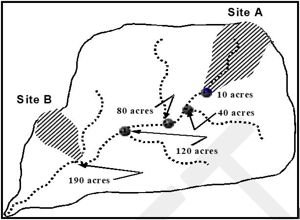
Site B is located downstream at the point where the total drainage area is 190 acres. The site itself is only 6 acres. The first tributary junction downstream from the 10% point is the junction of the site outlet with the stream. The total 190 acres is modeled as one basin with care taken to estimate the time of concentration for input into the hydrologic model of the watershed. The model shows that a detention facility, in this case, will actually increase the peak flow in the stream.
3.8 SCM Selection and Feasibility
This section provides requirements and supporting guidance for the selection of SCMs to meet the local government stormwater management standards. There are many factors to consider when selecting a SCMs for a drainage area, which are presented comparatively in this section. Table 3.8.1.1 presents SCM feasibility based on land-use characteristics. Table 3.8.2 1 presents physical and other (non-physical) feasibility factors. All of the information provided in these tables are described in greater detail in the individual SCM design specifications provided in Chapter 5 Sections 5.1 through 5.14.
Table 3.8.1.1
SCM Selection Based on Land Use
Submerged Gravel Wetland
Underground Detention (does not provide stormwater quality treatment)
Urban Bioretention
Water Quality Basin
= Generally, well-suited for this application with proper protection and regular maintenance
= Generally, not well-suited for this application due to feasibility, protection, or maintenance concerns Check design specification in Chapter 5
= Not allowed for this application without prior local government approval.
Northeast Tennessee Water Quality SCM Manual
Table 3.8.1.2 SCM Feasibility Table
Northeast Tennessee Water Quality SCM
3.9 References
Allred-Coonrod, J.E., 1991, Safety Grates in Open Channels, MS Prof. Paper. University of New Mexico, Albuquerque NM
American Society of Civil Engineers, 1985, Stormwater Detention Outlet Control Structures, Task Committee on the Design of Outlet Control Structures, ASCE, New Your, N.Y.
ARC. Georgia Stormwater Management Manual Volume 2 Technical Handbook, 2016 Edition. Atlanta Regional Commission, 2016
Brater, Ernist F., Horace W. King. 1976. Handbook of Hydraulics. 6th ed. NY: McGraw Hill Book Co.
Chow, C. N. 1959. Open Channel Hydraulics. New York: McGraw Hill Book Company.
City of Topeka, Kansas. Stormwater BMP Design Handbook, January 2021 Version.
Ferguson, B. and Debo, Thomas. On-Site Stormwater Management. 1990.
Knox County, Tennessee. Knox County Stormwater Management Manual Volume 2, Technical Guidance. 2006.
Maryland Department of the Environment. 2000. Maryland Stormwater Design Manual, Volumes I & II Online. Accessed February 2024. Center for Watershed Protection (CWP), Ellicott City, MD.
Metcalf & Eddy, Inc., 1972, Wastewater Engineering, McGraw Hill, New York.
National Oceanic and Atmospheric Administration (NOAA). Evaporation Atlas for the Contiguous 48 United States. NOAA Technical Report NWS 34, Washington DC, 1982.
Pitt, Robert. Small Storm Hydrology. Unpublished report. Department of Civil Engineering, University of Alabama at Birmingham, 1994.
Sandvik, A. 1985. Proportional Weirs for Stormwater Pond Outlets. Civil Engineering, March 1985, ASCE pp. 54-56.
Schueler, Thomas R., July 1987. Controlling Urban Runoff: A Practical Manual for Planning and Designing Urban BMP’s, Department of Environmental Programs Metropolitan Washington Council of Governments, Metropolitan Information Center, Washington, DC.
Urban Drainage and Flood Control District (UDFCD). 1999. Criteria Manual. Denver, CO.
UDFC. Urban Storm Drainage Criteria Manual Volume 3. August 2013. Urban Drainage Flood Control District. Mile High Flood District. Lakewood Colorado. U.S. Army Corps of Engineers, 1988. Hydraulic Design Criteria (HDC), USAE Waterways Experiment Station, Vicksburg, MS.
U.S. Bureau of Reclamation (USBR) , 1978. Design of Small Canal Structures.
U.S. Department of Agriculture, Natural Resource Conservation Service, Engineering Division. 1986. Urban Hydrology for Small Watersheds. Technical Release 55. Natural Resource Conservation Service (NRCS).
Virginia Department of Conservation and Recreation. Virginia Stormwater Management Handbook, First Edition, 1999.
CHAPTER 4: LOW IMPACT DEVELOPMENT
4.7.3
CHAPTER 4: LOW IMPACT DEVELOPMENT
4.1 Introduction
In the distant past, the design of stormwater management features for a proposed development was almost an afterthought. Areas of potential flooding were considered when laying out pavement and buildings, but the design of stormwater infrastructure was largely a product of the layout. This approach changed slightly when communities sought to reduce the rate of runoff discharging from a development The location and approximate size of the onsite detention basin(s) needed to be identified along with the pavement/building layout, which further influenced the stormwater conveyance system design. And detention requirements can result in mixed outcomes. While flooding is prevented on properties in close proximity to the new/re-development, detention basins can actually increase peak flows and exacerbate flooding further downstream. In fact, are standard stormwater desi4gn approaches seek only to convey and dispose of stormwater. Thus, they often do very little to mitigate the stormwater management challenges communities experience in the present day in terms of volume and pollution.
In contrast, employing a low impact development (LID) approach to stormwater design can mitigate stormwater’s negative impacts. LID includes several site design practices (herein called LID practices) that lay-out the natural and proposed manmade site elements in a way that reduces the stormwater impact. Additional LID techniques come in the form of green infrastructure (GI) stormwater control measures (SCMs) included in Chapter 5 (SCM Design Specifications). At the level of an individual development, the primary goals of LID are:
Using natural hydrology as a framework for development design.
Managing stormwater as close to the point of origin as possible, minimizing the need for large-scale runoff collection and conveyance
Reducing the environmental impact “footprint” of the site by preventing stormwater impacts rather than mitigating them, while retaining and enhancing the owner/developer’s purpose and vision for the site.
Utilizing simple, nonstructural methods for stormwater management that are lower cost and lower maintenance than SCMs.
Creating a multifunctional landscape.
On a city-wide scale, LID can support community expansion and growth while avoiding the negative impacts of increased stormwater, or at least do not rise beyond present levels.
Reduction of adverse stormwater impacts using LID should be the first consideration of the design professional. Operationally, economically, and aesthetically, LID designs offer significant benefits over treating and controlling runoff downstream. Therefore, it is often advantageous to explore and exhaust all options for LID before considering structural stormwater controls.
This chapter provides more detail on how LID designs work, then describes a number of non-structural stormwater LID practices that can be used during development layout and design. GI-SCMs are fully described in Chapter 5 (SCM Design Specifications).
4.2 LID Explained
4.2.1
The Importance of Plants and Soils
As a development design approach, stormwater LID strives to mimic natural hydrology (see information on the hydrologic cycle in Chapter 1) on a developed property. Natural hydrology is dependent on water infiltration into soil, evaporation, and transpiration via plant life. Thus, designing a development with an eye toward healthy plants and uncompacted, natural soil underpins LID techniques.
Plants and soil work within in a self-maintaining cycle when land disturbance is minimized, and appropriate plant diversity is maintained. The health and stormwater management capabilities of the soil affects the health and stormwater capabilities of plants, and vice versa. Well-drained and moderately well-drained soils have numerous void spaces that can store and transmit water and surface nutrients beneath the surface crust, supporting healthy plant growth both above and below ground. The nutrient filled soil also provides space and food for soil organisms. The activities and life cycles of these organisms assist in maintaining soil permeability and chemical characteristics to further support plant life. In turn, healthy plants have strong and vigorous root growth, which keeps soil permeable, aids in infiltration and subsurface nutrient delivery to soil organisms. Aboveground, leaf growth and decay cycles deliver organic matter to the ground, which migrate into the soil when it rains, thus removing rainfall and pollutants.
The role that plants and soil can play in stormwater management for urban and suburban landscapes must not be underestimated. When properly protected and managed, plants and soil can provide substantial stormwater volume reduction, even in urban developments. This is the primary premise in LID designs; maximizing, preserving, and in many cases, using, healthy plants and soil in a GI-SCM to manage stormwater generated by land development. The LID design techniques and GI-SCMs included in this manual consider or use soil and/or vegetation to either limit or manage stormwater on a land development (see Figure 4.2.1.1).
and Design
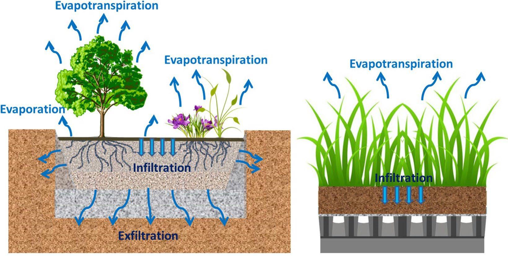
4.2.2
Plants and Soil as LID and GI-SCM Design Elements
Since plants and soil are so important to LID-based designs, they must be considered by designers and municipal plan reviewers as site and stormwater design elements. This typically means understanding and considering the property’s predevelopment hydrology as the layout of buildings and impervious surfaces is laid out. For example, in-situ hydrologic soil information (e.g., A, B, C, D, and urban/fill) is useful for LID designs, as clearing, grading, and building/pavement placement can be confined to those areas with the poorest draining soils, while preserving, and possibly using, well-draining soils for
Figure 4.2.1.1 Typical Land Development Planning
Steps Example (Source: Ebrahimian Ali et al, 2019)
Bioretention Area Green Roof
stormwater management. Similar evaluations can be made for pre-development land cover (i.e., existing vegetation and impervious areas).
Plants and soil are addressed as stormwater management design elements in this manual as follows.
The Pre-Development Hydrology Map is a portion of Water Quality Management Plan (WQMP) that documents the existing hydrologic condition of a property prior to a proposed new- or re-development. The report includes mapping of soil and land cover (pervious vs. impervious), among other important features. it is discussed in detail in Section 4.3 of this chapter and the report’s required elements are Appendix D (Plan Preparation Checklist for WQMPs).
The non-structural LID practices described in this chapter target the preservation of native, uncompacted soil and native, healthy, and diverse plant populations to promote wide-area infiltration and evapotranspiration. The more a site designer can use LID design approaches, the more the land development’s response to rainfall will mimic a more natural hydrologic character.
The GI-SCMs included in Chapter 5 (SCM Design Specifications) use uncompacted soil to promote facility-level infiltration and/or biofiltration. Some also require a healthy and diverse plant cover to foster evapotranspiration. During small, frequent rain events, these SCMs can diminish the influence of impervious surfaces on the developed site. Although impervious surfaces can significantly elevate stormwater volume from pre-development levels, the utilization of GI-SCMs effectively reduces a portion of this volume while almost entirely eliminating pollutants.
4.3 Introduction to Non-Structural LID Practices
The reduction in stormwater volume and ideally, peak discharges, that can result from employing LID practices influences the size and cost of the onsite stormwater conveyance system and SCMs. Hence, LID practices can be viewed as both a water quantity and water quality management tool with ancillary benefits such as:
Reduced construction and maintenance costs
More aesthetically pleasing and naturally attractive landscape
Open space for recreation
Pedestrian-friendly neighborhoods
Increased property values
Protection of waterbodies, wetlands, wooded areas, and the habitats they provide for wildlife
Easier compliance with wetland and other resource protection regulations
The LID design practices addressed in this chapter are listed in Table 4.3.1. The table groups the practices into three major categories are described in Sections 4.4, 4.5, and 4.6.
Table 4.3.1 LID Design Practices
SECTION 4.4 DESIGN COLLABORATION AND EARLY PLANNING
4.4.3 Collaborate with multi-disciplinary design team 4.4.3 Pre-development hydrology map and conference
SECTION 4.5 PRESERVATION OF NATURAL FEATURES AND RESOURCES
4.5.1 Preserve stream corridors and floodplains
4.5.2 Preserve wooded areas and individual trees
4.5.3 Preserve undisturbed areas
SECTION 4.6 REDUCTION OF IMPERVIOUS SURFACES
4.6.1 Redevelopment and infill development
4.6.2 Reduce building and pavement footprints
4.5.4 Fit the design to the terrain
4.5.5 Minimize siting on porous or erodible soils
4.5.6 Reduce limits of clearing and grading
4.6.3 Disconnect small, paved areas
4.6.4 Use pervious or permeable surfaces
SECTION 4.7 USE OF NATURAL FEATURES AND PRESERVED AREAS
4.7.1 Use undisturbed areas and stream/shore buffers
4.7.2 Use natural drainageways and vegetated swales
4.7.3 Connect to parks/greenways and provide pocket parks
4.7.4 Create multi-functional landscaping
4.4 Design Collaboration and Early Planning
The best time to apply low impact development design techniques is early in the site design process, before the general design concept, site layout, and master design plans are developed. This section provides guidance for design professionals on data gathering and initial planning for land development designs. The guidance provided in this section can be used regardless of whether LID practices and GI-SCMs are included in the proposed design.
4.4.1 Land Development Planning Process
Figure 4.4.1.1 presents a typical progression of land development design. It begins with initial consideration of an undeveloped or previously developed property by the developer. A general design concept takes shape with a design professional, where a basic understanding of the general number and size of buildings and parking areas, as well as their probable location (for individual sites) or street and lot locations (if subdividing). The developer understands their potential return on investment (ROI) from the property, and whether the development makes financial sense.
Figure 4.4.1.1 Typical Land Development Planning and Design Steps Example
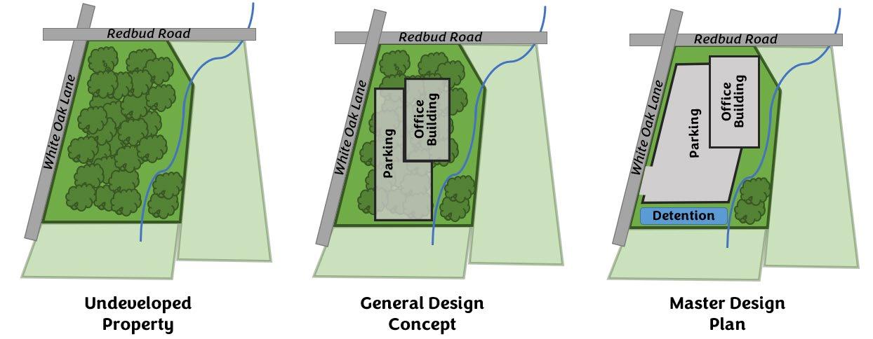
If the ROI is suitable for the developer, a master design is created. The lot or building and pavement configurations are refined, utility needs are understood, and the necessary clearing and grading is established. The design professional balances the developer’s overall concept and local government regulations in a way that can meet or exceed the expected ROI. From the stormwater perspective, it is this design that is provided to the local government for approval in the form of the WQMP.
This planning progression is the same when LID is considered, whether the site is originally undeveloped, as is shown in Figure 4.4.1.1, or has been previously developed. However, with LID, there are several additional steps that occur when creating the general design concept to consider LID practices and GI-SCMs. All but the last step shown in Figure 4.4.1.2 are discussed in this chapter.
Step 1 is addressed in Section 4.4.2 of this chapter.
Step 2 is addressed in Section 4.4.3 of this chapter.
Steps 3, 4, and 5 are the application of LID practices described in Section 4.4 of this chapter. After step 5, a general concept design in Figure 4.4.12 is well-established, and the design professional can easily move to the master design plan
Step 6 is the application of SCMs, which are addressed in Chapter 5 (SCM Design Specifications). The master design plan is well underway by this step.
Figure 4.4.1.2 Design Steps for LID Developments
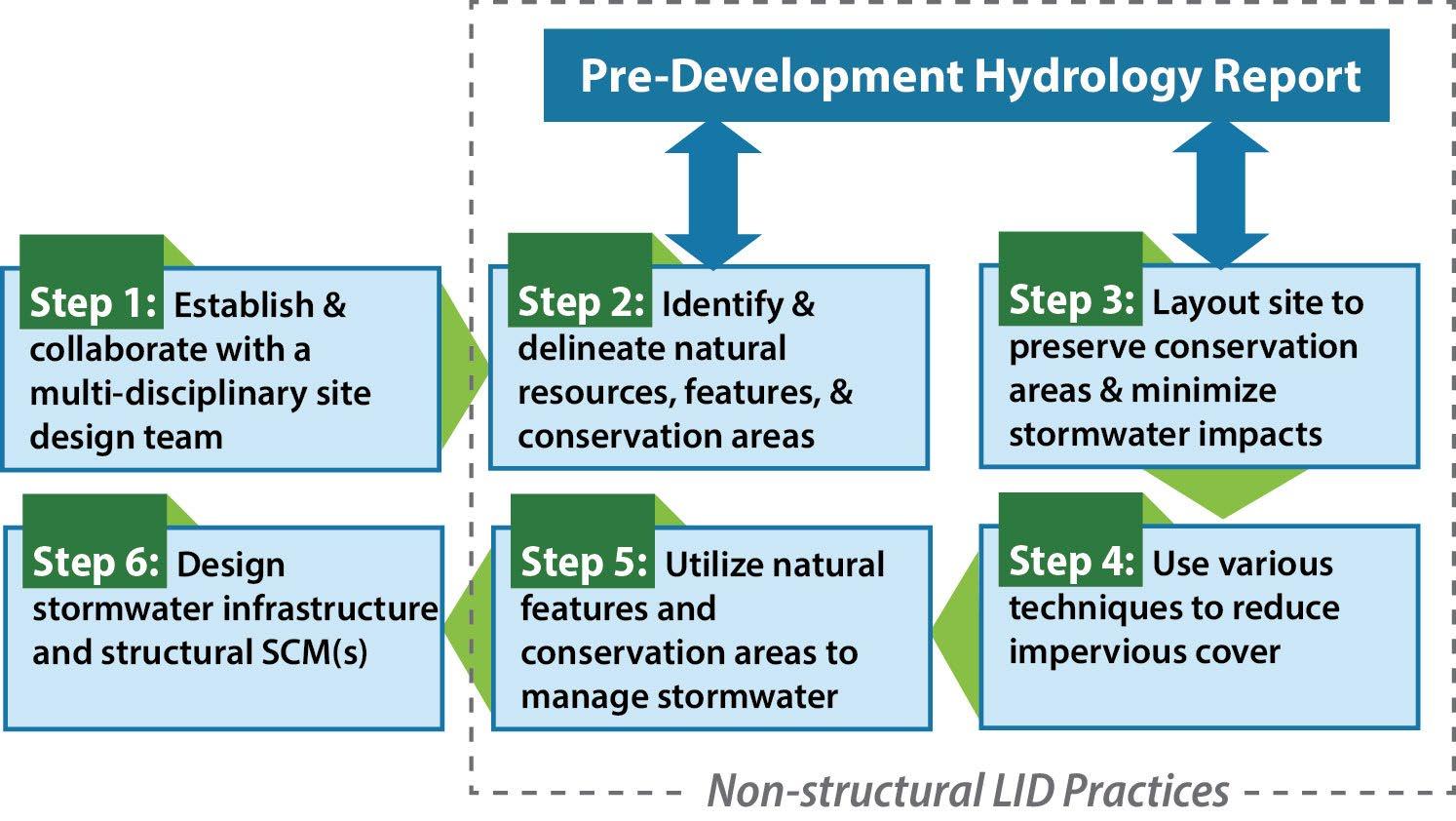
An important concept conveyed by Figure 4.4.1.2 is that the application of non-structural LID practices ends when a designer begins the analyses and computations for SCM design. In other words, LID planning takes place very early, so the layout of buildings, pavement, and pervious areas is established with application of LID practices before engineering design of site infrastructure, SCMs, roadways, and utilities, and before a site is cleared and graded. This early planning approach is critical to the successful use of LID practices because it allows the design team to see, then preserve, restore, and/or use, a site’s natural features for stormwater management. Thus, we fit the development to the site’s natural hydrology rather than the other way around. In contrast, site designers who attempt to fit the existing property to a preconceived or “cookie-cutter” layout, or who wait to consider LID practices until after the site layout and grading plans are established, are not likely to have a high degree of success applying LID.
4.4.2 Collaborate with a Multi-Disciplinary Design Team
A critical concept in Step 1 of Figure 4.4.1.2 that site designers should note is the necessity for early collaboration with a multi-disciplinary team to ensure successful LID designs. Successful LID designs demand knowledge and experience of plants and soil, which are considered design elements. As a result, stormwater designs are no longer the sole domain of the civil engineer. Rather, working with a team of skilled professionals and scientists to optimize the use of LID practices and GI-SCMs will, ideally, improve the developers ROI. Table 4.3.1 presents the disciplines and relevant skills that can help ensure LID design success.
When plants are included in LID designs, the local government strongly suggests the inclusion of a Registered Landscape Architect or a horticulturalist because of their knowledge of soil/plant interaction, and plant diversity, succession, and landscape templates. However, expanding the team further as indicated in Table 4.3.1 can provide substantial benefits, as the team can better maximize the use of natural features for stormwater management, while possibly minimizing
constructed features and their associated construction, materials, and maintenance costs. Regardless of which professionals comprise the design team, all members should be knowledgeable of, and preferably experienced in, stormwater management mechanisms and LID concepts. Local technical knowledge is preferred, especially where plant selection and maintenance are concerned.
Table 4.4.2.1 Design Team Disciplines and Relevant Skills
Discipline
Civil Engineering
Soil Science
Landscape Architecture
Horticulture
Forestry
Ecology
Skills Relevant to LID Designs
Hydrology, hydraulics, infrastructure, and utilities design, SCM design, stormwater quality and quantity control, design plan preparation
Soil health, profiles, texture, porosity, storage capacity, infiltration tests, borings, and restoration techniques
Multi-functional space design, open space function and design, hydrology, landscape design and templates
Functional landscape planning, plant varieties and needs, native plants, plant/soil health, stream buffer restoration, and long-term plant management
Health, preservation (or restoration), and management of wooded areas, tree selection for urban landscapes and green infrastructure SCMs, pest management
Desired wildlife vs pest habitats and management, stream buffer restoration and enhancement, sensitive flora and fauna avoidance/support
Geomorphology Stream restoration, bank stability, and stream health management in urban landscapes
The benefits of using a multi-disciplinary design team include the following.
Optimization/maximization of LID practices and multi-functional GI-SCMs
Robust understanding of how local, state, and Federal requirements for land developments can be met creatively and aesthetically, yet cost effectively
Robust stormwater design while potentially reducing costs for stormwater infrastructure and pavement
Potentially reduced needs for stormwater-related maintenance by future property owners for the long-term
Preservation or restoration of a property’s natural character and aesthetic features
These benefits can have the effect of meeting or exceeding the desired ROI of the land developer, while also maximizing the value of the property for future property owners. However, to ensure success, the entire team should come together well before the general design concept is developed and remain involved with the land development through site construction. The former will provide the greatest potential for the application of LID practices. The latter will ensure the protection and proper design and construction of SCMs.
4.4.3 The Pre-Development Hydrology Map and Conference
As explained in Chapter 2 (Relevant Regulations and Required Plans), a Pre-Development Hydrology Map is a sub-report that must be included with the WQMP regardless of whether LID practices are included in a proposed development design. The purpose of the report is to characterize the existing hydrologic conditions of a property. For a new development, the existing condition is an undeveloped condition. For a redevelopment, the existing condition is a developed condition. Both situations have a hydrologic condition that must be understood.
The Pre-Development Hydrology Map is developed for the reasons listed below, all of which can improve the developer’s understanding and estimation of the site’s ROI.
Optimizing the buildings, pavement, and stormwater SCM layout while avoiding, restoring, or using natural hydrologic features for stormwater control. Hydrologic characterization identifies hydrologic or environmental issues that must be considered during site design, whether LID is strongly considered. For example, potential onsite soil contamination due to a past land use may factor into the location of impervious surfaces (to eliminate infiltration in contaminated areas), if GI-SCMs are feasible, and if soil decontamination is required.
Identifying opportunities or limitations for LID practices and SCM feasibility.
Optimizing grading extents, construction needs and phasing, materials, and maintenance costs.
Mapping the site hydrology and other factors can allow the site design team and the local government’s plan reviewers to identify the potential need for additional data or information to support the future design. This keeps everyone “on the same page” and facilitates a more efficient design effort and plan review process.
Creating the Pre-Development Hydrology Map is really a mapping exercise of available data. Some of the useful data to include in the map is listed below. More detail is provided in Appendix D (Plan Preparation for WQMPs).
Topography (2 foot intervals or closer)
General land cover areas:
Undisturbed wooded areas and condition
Undisturbed non-wooded areas and condition
Managed turf or other managed landscape
Bare soil
Impervious (rooftop, pavement, gravel, etc.)
Hydrologic Soil Groups and urban fill or farmed soils
Waterbodies, wetlands, floodplains,
Sinkholes, seeps, springs, bogs, and swamps
Areas of prolonged wet conditions or flooding
Areas of ecological significance (such as endangered wildlife habitat)
Areas of shallow bedrock, high water table, hardpan, clay lenses, or other similar subsurface conditions, if known
Areas of known or suspected pollutants in the soil
Water supply, wellhead protection, or groundwater recharge areas
Existing conservation or protected areas
Existing utility corridors, buildings, pavement, and other areas to remain
Areas with geotechnical or structural concerns, contractive/expansive soils, etc.
Areas of cultural, historical, or archeological significance
It is recognized that some of the data listed in the table will be easy to gather by visual inspection or using maps available to the public (e.g., USGS Quadrangles, NRCS soil surveys, publicly available aerial photography, etc.), while other elements can require more involved engineering field tests or environmental surveys. While the collection of all the data listed is encouraged to develop a well-informed stormwater management vision for the site, performing geotechnical and environmental tests or surveys is not required to prepare the report. It is acceptable to use only readily available data to prepare the report.
Figures 4.4.3.1 and 4.4.3.2 present a rudimentary example of how a Pre-Development Hydrology Map can be used to guide a development layout The example is for a proposed redevelopment. Several LID practices and a GI-SCM are implemented in the example, all shown on the master design plan in Figure 4.4.3.2. These are: 1) restoration and preservation of a natural water feature (the daylighted stream); 2) restoration of a stream buffer; and 3) a pervious paver parking lot. These and more LID practices are described in Sections 4.5 through 4.7 GI-SCM design specifications are in Chapter 5.
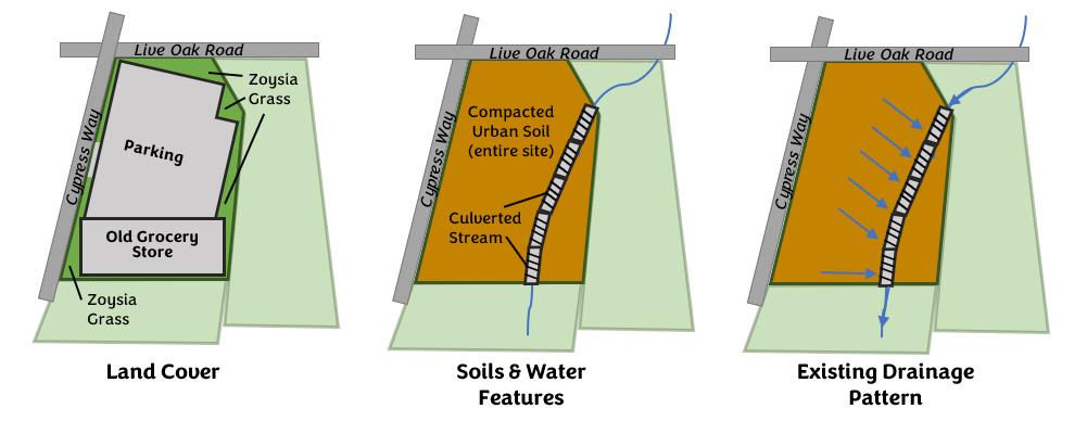
4.4.3.2 LID Design Progression Based on the Pre-Development Hydrology Map
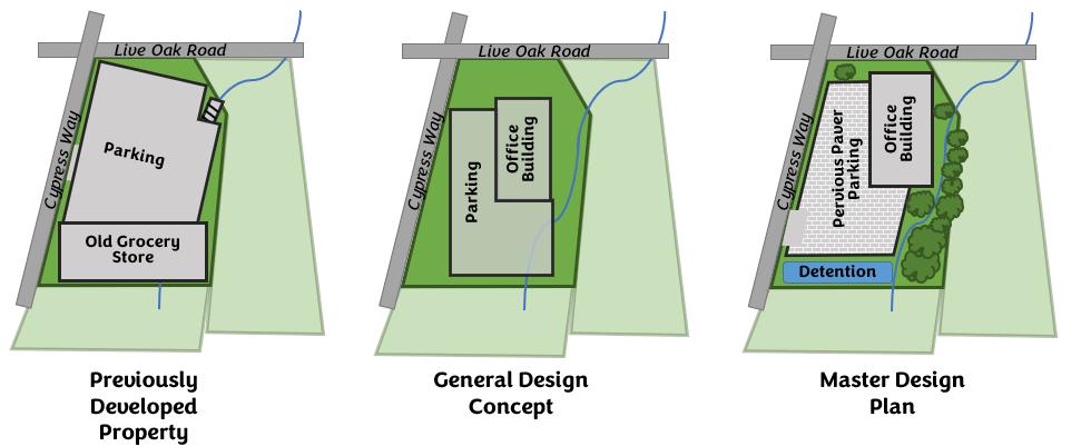
Consult the local government to determine if a meeting to review the Pre-Development Hydrology Map prior to submittal of the WQMP is mandatory. If not, design professionals may request a meeting after preparation of the Pre-Development Hydrology Map Stormwater designs will be not approved at the meeting. Rather, this is an opportunity for the design team and local government plan reviewers to discuss the potential water quality protection strategy for the proposed development. The objectives of such a meeting include:
review of the information provided in the report (and the master design plan if already determined)
discussion of potential limitations for application of SCMs
discussion of preliminary strategies and concerns for site clearing, grading, and construction
discussion of preliminary design strategies for erosion and sediment control, road geometry and layout, SCMs, stormwater easements, vegetated buffers, the use of LID practices, and any potential WQv reductions available for LID practices (see Appendix B).
determination of how the technical guidelines and criteria presented in this manual should be applied to the site.
Figure 4.4.3.1 Example Layers of a Pre-Development Hydrology Map
Figure
4.5 Preservation of Natural Features and Resources
After creation of the Pre-Development Hydrology Map to characterize the existing hydrology of the property (see Chapter 3), the layout of the future land development can begin to take shape. A number of LID design practices can be considered in this step to maximize hydrologic mimicry after development. The preservation of natural features and resources is integral to hydrologic mimicry and therefore, integral also to the success of LID designs. From a development design perspective, this these LID practices target preservation of native, uncompacted soils and vegetated open spaces, ideally in areas or ways that provide value to the property beyond hydrologic mimicry. For example, a preserved wooded areas can provide infiltration and evapotranspiration, but also reduces the cost of clearing and grading, provides a woodsy, natural landscape aesthetic, and may even provide amenity areas, such as walking trails or picnic areas.
Natural area preservation LID-BMPs are described in Sections 4.5.1, 4.5.2, 4.5.3, 4.5.4, 4.5.5 and 4.5.6
4.5.1 Preserve Stream Corridors and Floodplains
Preserve Stream Corridors & Floodplains
Description: Stream corridors and floodplains can be critical to water quality. They also provide infiltration, filtration, and evapotranspiration of stormwater, as well as habitat, shade, and bank stability.
Identify, delineate, and avoid land development in stream corridors and floodplains as much as possible. If such areas are already disturbed, that can be restored to a more natural condition.
Planning and Design Activities:
LID Design Practice
Key Benefits:
Preserves pre-development hydrology, and provides bank stability, shade, and habitat
Limits stormwater volumes and peak discharges
Provides undeveloped land for flood flows
Reduces clearing and grading
Provides natural character and aesthetic features
Perennial and ephemeral streams are fairly easy to recognize on land that has yet to be developed. However, taking notice of drainageways on properties that have already been developed is important, too, as these linear features may have been a natural stream prior land development and could benefit from restoration to a more natural form. Providing a wooded buffer for streams and natural drainageways can manage stormwater, act as a stream “right of way” during floods, and sustain the integrity of the watershed and stream ecosystem. Avoid clearing, grading, and development of these areas.
The Tennessee Department of Conservation (TDEC)) requires a minimum buffer of permanent stream buffer of 15feet (waters with available parameters for siltation or habitat alteration or unassessed waters, with average buffer width of 30-feet) and 30-feet (exceptional TN waters or waters with unavailable parameters for siltation or habitat alteration with average buffer width of 60-feet) Regardless of a stream’s regulatory status, a 60-foot or wider undisturbed buffer is preferred for stormwater filtration and infiltration, streambank stability, shade, and a supportive environment for both aquatic and bankside flora and fauna.
Ideally, stream buffers should be heavily wooded and left undisturbed. If the buffer does not meet these conditions, restore vegetation by planting native trees and preventing encroachments.
Development in floodplains and Special Flood Hazard Areas (SFHAs) should be avoided for buildings and other structures to minimize risk to human life and property damage and allow the area to accommodate flood flows.
Ideally, avoid any clearing, grading, and development in floodplains and leave them undisturbed. This prevents having to deal with regulations pertaining to development in floodplains and provides, to some degree, the code conflicts that sometimes occurred between floodplain rules and stream corridor rules (see Figure 4.5.1.1).
Where development in floodplain areas cannot be avoided, minimize the placement of impervious areas in the floodplain and comply with local government regulations.
Figure 4.5.1.1 Floodplain Boundaries in Relation to a Stream Buffer
Stream floodplains and stream buffers are two different features. Floodplains are low-lying flat lands that border streams and rivers. When the stream overflows its channel, the floodplain provides storage and conveyance of the excess flows. Floodplain boundaries are determined for flood events using mathematical models. In contrast, a stream buffer is an undisturbed streamside corridor set aside for purposes of water quality, streambank stability, and habitat preservation. Depending on the site topography, the 100year floodplain boundary may be inside or outside of a stream buffer. Source: ARC, 2001

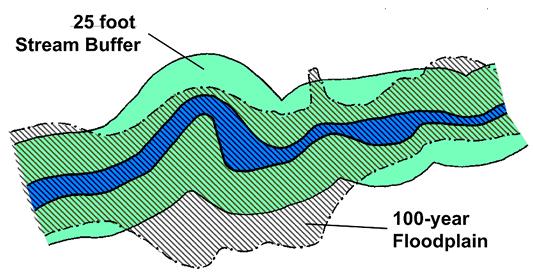
The remainder of this page was intentionally left blank.
4.5.2 Preserve Wooded Areas and Individual Trees
Preserve Wooded Areas and Individual Trees
Description: Stream corridors and floodplains can be critical to water quality. They also provide infiltration, filtration, and evapotranspiration of stormwater, as well as habitat, shade, and bank stability. Wooded areas that coincide with other natural features are key areas to preserve. For previously developed properties without many trees, use reforestation techniques to create wooded areas (see below).
Planning and Design Activities – Existing Tree Protection
Key Benefits:
LID Design Practice
Preserves pre-development hydrology
Limits stormwater volumes and peak discharges
Reduces clearing and grading
Provides shade, habitat, and improved air quality
Provides natural character and aesthetic features
May increase the value of the property after development
The following activities should be done to preserve wooded areas and mature trees.
Develop a Pre-Development Hydrology Map. Delineate the boundaries of wooded areas and mark the locations of individual mature trees. The items in the map are listed in the WQMP checklist provided in Appendix D Take special note of wooded areas or multiple mature trees that coincide with other features or resources, such as stream corridors and floodplains, native and well-draining soils, and endangered species habitats. These coincidental areas should be more highly valued for post-construction preservation because they can provide an enhanced stormwater or environmental function.
Once the site layout is better determined, individual, healthy, mature trees (not located in a wooded area) that are not located where buildings or pavement is planned should be preserved and integrated into the post-construction landscape.
Clearly identify trees and wooded areas to be preserved, specifying measures to protect these features during and after construction on the WQMP and erosion prevention and sediment control (EPSC) plan See Table 4.5.2.1
Table
Protection Measures for Existing Wooded Areas and Mature Trees
For individual trees, install high visibility fencing around the root zone, extending at least to the canopy drip line. For wooded areas, install fencing around the area along the drip line edge of the area.
In the fenced area, do not:
• allow vehicles or heavy equipment
• wash equipment or dump chemicals
• store construction materials or chemicals
• allow erosion or sediment discharges
Minimize foot traffic in fenced areas. If unavoidable, build boardwalks or lay sheets of plywood to limit compaction.
Water preserved trees as needed to ensure their health during construction.
Do not direct roadway runoff to the tree. The dripline area under an existing, mature tree is not suitable for use as a stormwater SCM. This may cause localized flooding and stress or kill the tree being preserved.
Do not change the grade of the site near the tree(s) root zones. Within the drip line, avoid exposing the roots or covering them with extra soil. Either of these will stress or kill the tree.
For trees preserved near impervious areas, consider using permeable pavers near the tree to allow rainwater to percolate into the soil provide water to tree roots. Bypass flood flows from the pavers.
If drainage patterns will change, ensure preserved trees will have a source of water for their root zones.
4.5.2.1
Planning and Design Activities – Reforestation
The following activities should be done to reforest areas of a developed property.
On the Pre-Development Hydrology Map (see Section 4.4.3 and Appendix D), delineate areas where reforestation can provide maximum benefit and also have a good chance of survival.
• Areas that provide maximum benefit are those where other natural features or resources are present, such as stream corridors and floodplains, native and well-draining soils, and endangered species habitats These areas should be more highly valued for post-construction preservation and reforestation because they can provide an enhanced stormwater or environmental function.
• The quality of the area is also important. Quality sites have a higher probability of supporting long-lived and healthy trees than poor sites. Urban environments are challenging for tree health and survival. Soil contaminants, high temperatures, high winds, compacted soil, poor drainage, and confined areas for root expansion should all be considered as challenges to a long tree life.
Once the site layout is better determined, designate locations where immature trees can be planted and integrated into the post-construction landscape. Remember, a single tree or group of trees planted primarily for landscape aesthetic IS NOT a stormwater control measure If stormwater treatment is needed by these trees, design the appropriate SCM that includes trees (e.g., bioretention area, urban bioretention, or green infrastructure manufactured treatment devices (GI-MTDs). Design specifications for all of these SCMs are provided in Chapter 5.
For a planned reforestation area, collaborate with a forester to develop the reforestation design, select the appropriate tree species (native is preferred), and oversee tree installation. The forester should remain involved for at least two growing seasons after the reforestation area has been planted.
For individual trees, a forester or landscape architect should be included in the design to determine appropriate tree placement, species, installation, and maintenance.
On EPSC and WQMP plans, clearly identify the location of tree installation and reforestation areas. Specify protection measures during and after construction per the guidance of the forester or landscape.
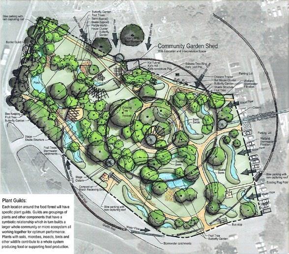

Figure 4.5.2.1 Examples of Urban Reforestation
Left: Site Plan for an urban food forest in Austin TX. Credit: American Forests; Right: Urban forest in Chattanooga TN. Source: Trees for Energy Conservation
4.5.3 Preserve Undisturbed Areas
Preserve Undisturbed Areas
Description: Undisturbed areas are areas that have not yet been developed, or otherwise graded, tilled, or compacted by man. They can be excellent areas for infiltration, filtration, and evapotranspiration because they usually have uncompacted, native soil and deeplyrooted vegetation. The best undisturbed areas for preservation are those located on well-drained, native soils.
Discussion:
LID Design Practice
Key Benefits:
Preserves pre-development hydrology
Limits runoff volumes and peak discharges
Reduces clearing and grading
Provides natural character
Undisturbed areas are hard to find in urban and suburban settings. However, they do exist, even if they are only on small pockets of land on a property that is largely developed. These areas can be highly valuable from a stormwater management perspective, even if they are not considered “buildable” land. In northeast Tennessee, it is not uncommon to find low-lying or even “swampy” areas. Many of these features already play a strong role in mimicking the natural hydrology of a property, often by flushing stormwater from pervious areas through and off the property. However, from a stormwater management perspective, the most valuable undisturbed areas are probably those located along stream corridors (i.e., natural stream buffers) or in the same areas as native, well-draining soils. Leaving these areas undisturbed can protect local streams, reduce stormwater runoff, and sustain the integrity of the watershed and stream/bayside ecosystems. Avoid clearing, grading, and development of these areas.
Planning and Design Activities:
The following activities should be done to preserve undisturbed areas.
On the Pre-Development Hydrology Map (see Section 4.4.3 and Appendix D), delineate the areas that are believed to be undisturbed by modern man. Make special note of undisturbed areas along stream corridors and where native, well-draining soils exist.
Develop the site layout, preserving the specially noted areas first. Once the site layout is better determined, allow any remaining undisturbed areas to remain (avoid clearing and grading in these areas), if possible. A more natural landscape for the future development can allow these areas to blend into the aesthetic.
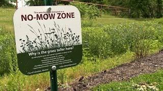
Collaborate with a forester or horticulturalist if any of these areas require vegetation enhancement. Ensure this is done in a way that will not compact the underlying native soils. Avoid using heavy equipment and vehicles in the area during enhancement installations.
Clearly identify the location of undisturbed areas that will be preserved on EPSC and WQMP plans. Specify and install protection measures during construction to avoid accidental clearing or grading, encroachments, erosion of the areas, or sediment discharges into the areas.
For post-construction, install signs that educate landscapers and/or the public as to the function and maintenance (or lack thereof) of these areas and the importance of leaving them undisturbed.
Figure 4.5.3.1 Example of Protection Sign
(Source: City of Columbia MO)
4.5.4 Fit the Design to the Terrain
Fit the Design to the Terrain LID Design Practice
Description: The layout of buildings, roads/streets, utilities, and other site infrastructure should, as much as possible, conform to the existing topography and natural features of the land. Streams, natural drainage ways, steep slopes, wetlands, and other features should be preserved by designing road layouts around them. Lots/buildings should utilize natural grading and drainage systems.
Key Benefits:
Preserves the natural hydrology and drainageways of a site
Reduces the need for clearing and grading
Provides a natural framework for site layout, design, and stormwater management
Figure 4.5.4.1 Comparison of Traditional Site Layout and “Fit to the Terrain” Layout
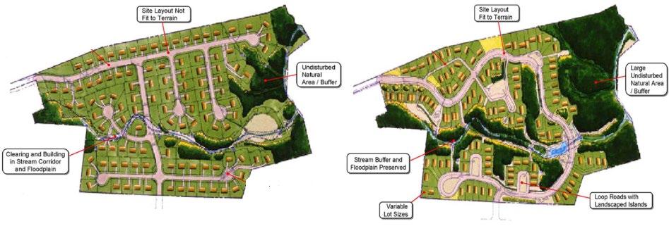
Planning and Design Activities:
Site designers should perform the following activities to implement this LID design practice.
Lay out the site to conform or “fit” the natural landforms and topography of the property, minimizing grading as much as possible. This preserves the natural hydrology and features on the site, and reduces clearing plants and grading native, uncompacted soil. Avoid floodplains and low-lying areas.
Roadway patterns should match the terrain, following natural contours. This provides buildable areas while reducing stormwater infrastructure (i.e., bridges and culverts). Consider viable access points for parking areas and buildings, avoiding steep slopes.
In areas that slope, the major axis of buildings should be oriented parallel to existing contours.
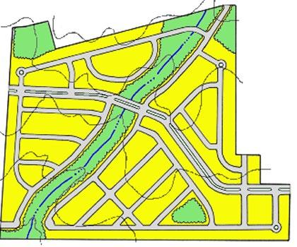
Figure 4.5.4.2 Fluid Grid Street Pattern
Left: A traditional residential layout means wide scale clearing and grading, loss of stream buffers, and development in floodplains. Right: The “Fit to Terrain” layout provides the same number of lots, but reduces clearing and grading, provides sufficient buffer for stream health, and avoids development in the floodplain. Adapted from: Georgia Stormwater Management Manual, 2001
(Source: ARC, 2016)
4.5.5 Minimize Siting on Porous or Erodible Soils
Minimize Siting on Porous or Erodible Soils
Description: Native, porous soils such as sand and sand mixes provide natural opportunities for stormwater infiltration. These areas should be preserved to support hydrologic mimicry after land development, and as potential options for the management of runoff from developed areas of the property. Unstable or easily erodible soils must be avoided altogether due to their greater erosion potential.
Discussion:
Soils with maximum permeabilities (hydrologic soil group A and B soils such as sands and sandy loams) allow for the most infiltration of stormwater into the subsoil. These areas should be conserved as much as possible and incorporated into undisturbed natural or planned open space areas. Conversely, buildings and other impervious surfaces should be located on those portions of the site with the least permeable soils (hydrologic soil groups C and D).
Development on highly erodible or unstable soils should be avoided for land disturbing activities and buildings to prevent erosion and sedimentation problems as well as potential future structural problems.
Planning and Design Activities:
LID Design Practice
Key Benefits:
Preserves the natural hydrology of a site
Provides areas for natural runoff reduction and structural LID-BMPs without underdrains
Reduces the need for clearing and grading
Reduces needs for erosion prevention and sediment control
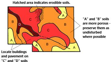
The following activities should be done to minimize development on porous and erodible soils.
A Tennessee licensed soil scientist should be consulted for this exercise, as they can easily identify highly porous and highly erodible soil. They can also identify other soils of concern, such as those with high shrink-swell potential.
On the Pre-Development Hydrology Map (see Section 4.4.3 and Appendix D), delineate areas of native soils that have maximum permeabilities (typically hydrologic soil groups A and B).
Also delineate areas of areas of highly erodible soil. The United States Department of Agriculture (USDA) National Resource Conservation Service (NRCS) prepares lists of highly erodible soils, called the Highly Erodible Land (HEL) Soil List for each state. It can be found online (enter “USDA-NRCS HEL Soil List” into search bar) See Figure 4.5.5.1
Develop the site layout, preserving areas of porous and erodible soils first. Once the site layout is better determined, allow any areas that are left to remain undisturbed, if possible.
Clearly identify the location of areas that will be preserved as “undisturbed” on EPSC and WQMP plans. Specify and install protection measures during construction to avoid accidental clearing or grading, encroachments, erosion of the areas, or sediment discharges into the areas. If these areas will be disturbed for landscape purposes, avoid the removal of topsoil and the use of vehicles and heavy equipment.
Figure 4.5.5.1 Example Soil Map (Source: SCMM, 2016)
4.5.6 Reduce Limits of Clearing and Grading
Reduce Limits of Clearing and Grading
Description: Clearing and grading should be limited to the minimum amount needed for the development and road access. Site foot-printing should be used to disturb the smallest possible land area on a site.
Planning and Design Activities:
LID Design Practice
Key Benefits:
Preserves the natural hydrology and drainageways
Reduces the need for clearing and grading
Provides shade, habitat, and improved air quality
Provides natural character and aesthetic features
Minimal disturbance methods should be used to limit the amount of clearing and grading that takes place on a development site, preserving more of the undisturbed vegetation and natural hydrology of a site. Methods that support minimum disturbance are as follows.
Establish a limit of disturbance (LOD) based on maximum disturbance zone radii/lengths. These maximum distances should reflect reasonable construction techniques and equipment needs together with the physical situation of the development site such as streams, shoreline, or soils. LOD distances may vary by type of development, size of lot or site, and by the specific development feature involved.
Map all the LODs to identify the smallest possible land area on a site which requires clearing or land disturbance. This is called “site footprinting.” Examples of site footprinting is illustrated in Figure 4.5.6.1.
Using the LID design practice called “Fit the Design to the Terrain” (Section 4.5.4 above) is especially well-suited to limiting the limits of clearing and grading.
Clearly identify the location of areas that will be preserved versus those that can be cleared and graded on CBMP and stormwater management plans. Specify and install protection measures during construction to avoid accidental clearing or grading, encroachments, erosion of the areas, or sediment discharges into the areas.
Consider the specification and use of special procedures or equipment which will reduce land disturbance. For example, the use of compact machinery when grubbing, grading, loading, or hauling in close proximity to preserved areas can help construction site personnel better navigate these areas and avoid accidental encroachments.
Figure
4.5.6.1 Examples of Mass Grading and Site Footprinting
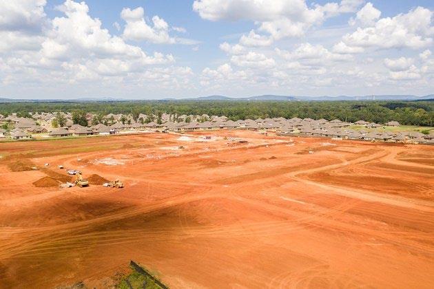
Left: Mass grading removes or compacts native soil and greatly reduces the potential for LID practices. (Source: Reed Contracting)
Right: An example of site footprinting, confined to the roadway, ROW, and a portion of the home sites. (Source: Specialty Grading)

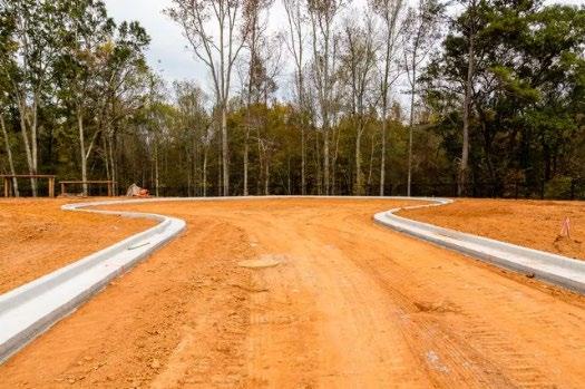
4.6 Reduction of Impervious Surfaces
As the future land development layout takes shape, utilizing LID design practices to preserve natural features (refer to Section 4.5), site designers can explore methods to potentially minimize impervious surfaces such as rooftops and pavements in the development (refer to Figure 4.6.1). LID design practices outlined in Sections 4.6.1, 4.6.2, and 4.6.3, along with GI-SCMs detailed in Chapter 5, offer various methods to diminish impervious surfaces.
Unlike other LID design practices, the ability of site designers to reduce the amount of imperviousness on a site is limited by local land development codes for streets, driveways, and parking lots. Local rules for minimum street widths, lane and ROW requirements, parking lot minimums, and pavement surfaces are all in play and must be followed. To the degree possible, the policies and guidance provided in this Manual do not conflict with local government land development regulations.
Figure 4.6.1 Stormwater Impacts from Impervious Surfaces and Pervious Surfaces (Adapted: Chesapeake & Atlantic Coastal Bys Trust Fund, 2013; Graphic: Integration and Application Network & Univ. of Maryland Center for Env. Science.)
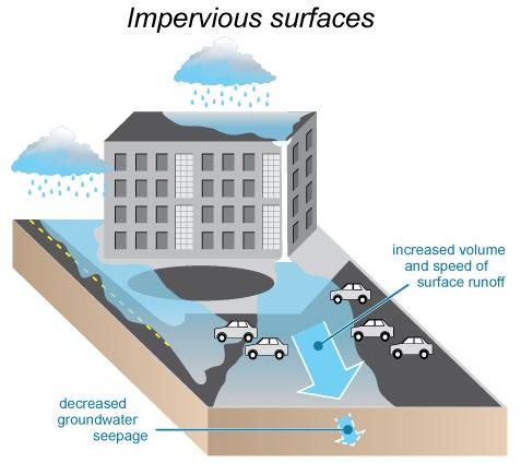
Impervious surfaces (roads, roofs, parking areas) increase the volume, speed, and temperature of runoff. This fast surge of water erodes stream banks and beds, reduces infiltration, and delivers warm, polluted flows into local streams and lakes.

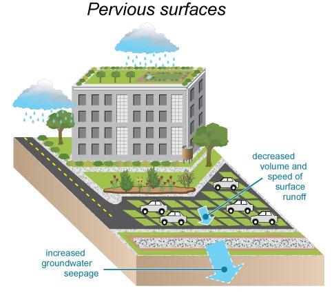
Pervious surfaces (green space, trees, and pervious pavement) decrease the volume and speed of runoff. Water seeps into the ground, or filters through vegetation, delivering cleaner and cooler water into local streams and lakes.

The remainder of this page is intentionally left blank.
4.6.1 Redevelopment and Infill Development
Redevelopment and Infill Development
Description: Redevelopment and infill strategies effectively minimize impervious surfaces compared to similar developments in suburban or rural regions. These practices align with LID principles, capitalizing on existing supportive infrastructure like roads and sewers, thereby reducing the necessity for additional construction to service the property
Discussion:
LID Design Practice
Key Benefits: When contrasted with new developments, redevelopment and infill projects offer:
Community saves costs by using existing infrastructure and services; developers cut expenses through minimized clearing/ grading
Often does not increase (and may decrease) impervious surface area (redevelopment only)
Redevelopment creates new buildings/pavement on a previously developed lot. Infill developments occur on vacant land within an existing community, enclosed by other developed properties. The term "infill" illustrates that the existing area is mostly built-out and the new development is "filling in" the gaps. Redevelopment and infill development can include the following.
Demolishing an existing building (and pavement) on a lot, creating a new site layout, and constructing a new residence or non-residential development in the same place
Single-family or multi-family homes being built on vacant lots in an existing neighborhood, or commercial or industrial properties built on vacant parcels in an established commercial/industrial area
Subdividing a lot or property within an existing established area into two or more lots and developing or redeveloping the newly created lots
Revitalizing a neighborhood or urban area through a mix of repurposing existing properties, demolition and redevelopment, and infill development on vacant lots
Planning and Design Activities:
The following activities should be done when considering redevelopment or infill development.

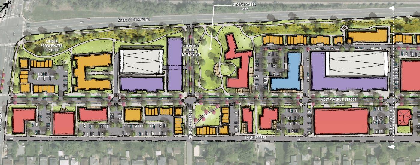
Consult real estate agents, local agencies, or the local government to find potential properties for re- or infill development. Departments that may be able to help are those involved with planning and zoning, neighborhood development, and historic development.
Develop a Pre-Development Hydrology Map (see Section 4.4.3 and Appendix D). Even though the area is already developed, there may be opportunities to use LID design practices to restore hydrologic features. Examples include daylighting a previously culverted stream or reducing existing pavement in favor of a small green space.
Work with existing topography, street and sidewalk layouts, and utilities to design building and parking areas. In some areas, zoning overlays, historic districts, or special design rules may exist and will need to be followed.
Figure 4.6.1.1 W. Walnut St. Redevelopment in Johnson City (Source: KimleyHorn)
4.6.2 Reduce Building and Pavement Footprints
Reduce Building and Pavement Footprints
Description: Finding reasonable ways to limit the size of buildings and pavement on a development is an obvious approach to employ when seeking natural hydrologic mimicry. Less impervious surface means less land disturbance, lower runoff volumes, and lower peak discharges. It also can provide significant stormwater benefits (see right) and, in some cases, reduce construction costs.
Key Benefits:
LID Design Practice
Preserves the natural hydrology of a site
Facilitates greater use of preservation-focused nonstructural LID-BMPs
Reduces the need for clearing and grading
Reduces the size and cost of site infrastructure
Planning and Design Activities: The following activities should be done for impervious area reductions.
Use the Pre-Development Hydrology Map (see Section 4.4.3 and Appendix D) and the natural preservation LID design practices (see Sections 4.5.1, 4.5.2, 4.5.3, 4.5.4, 4.5.5 and 4.5.6) to optimize locations and sizes for buildings and pavement.
Consider the following design approaches (where feasible and allowed by locally adopted land development rules,) to reduce impervious surfaces.
• Redevelop existing or choose to infill properties instead of developing green space (see Section 4.6.1)
• Use shared driveways and parking with other properties in the same area (Figure 4.6.2.1)
• Employ designs favoring shared driveways or single-lane roads in residential neighborhoods/lots. (Figure 4.6.2.2)
• Minimize the amount of parking to only that required by the local government
• Use porous or permeable surfaces for parking where feasible (see Section 4.6.4 and Chapter 5)
• Increase the vertical density for parking and buildings, instead of the impervious footprint (i.e., build upward instead of outward)
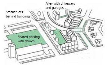
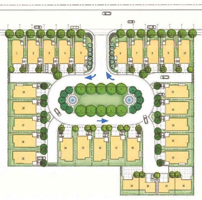
Figure 4.6.2.1 Example Shared Parking Plan (Source: City of Falls Church, VA)
Figure 4.6.2.2 Example Single Lane Road Layout (Adapted from: ProBuilder.com)
4.6.3
Disconnect Paved Areas
Disconnect Small Paved Areas
Description: Pavement disconnection is a technique that allows stormwater from small storms to discharge in vegetated areas that allow for infiltration, filtration, and increased time of concentration. This approach is generally applicable to small or narrow pavement areas, such as driveways, sidewalks, trails, and patios.
Planning and Design Activities:
LID Design Practice
Key Benefits:
Cost conscious stormwater quality method for small, paved areas
Can provide stormwater for driveways and entrance ways that may be difficult to include in onsite treatment SCMs
The following activities must be done when considering pavement disconnection.
Once the site layout is established, seek small areas of pavement that can be disconnected from other impervious areas or the onsite stormwater conveyance system during small storm events, or areas that will not discharge to the onsite conveyance system (such as a driveway into the property from the main roadway).
Inadvertent impacts must be considered. Follow the minimum requirements stated below. This practice is not suitable for large, paved areas, or those along streams or other potentially erosive or sensitive areas.
Pavement disconnection must meet the following minimum requirements.
The maximum contributing flow path of the impervious pavement being disconnected is 50 feet.
The length and width of overland flow over the vegetated pervious area must be greater than, or equal to, the length and width of the contributing flow path over the impervious area.
The overland flow must be sheet flow into and over the vegetated pervious area.
The soil of the vegetated pervious area must be well-drained or moderately well-drained. For native soils, this is typically hydrologic soil group A or B. For pervious areas that have been disturbed, soil restoration to eliminate compaction and improve soil permeability is allowed. Consult a Tennessee licensed Soil Scientist, Registered Landscape Architect, or agricultural extension for guidance on soil restoration.
The slopes for impervious and vegetated areas must be less than 5%
No more than 1,000 ft2 of pavement may discharge to the pervious area at a single location.
Permanent erosion prevention measures, such as a gravel strip is required where discharges may concentrate. Conversely, non-concentrated discharges along pavement edges (see Figure 4.6.3.1) do not necessitate permanent erosion control measures. Instead, focus on installing vegetation and stabilizing the area until it becomes well-established.
Philadelphia Water Department)
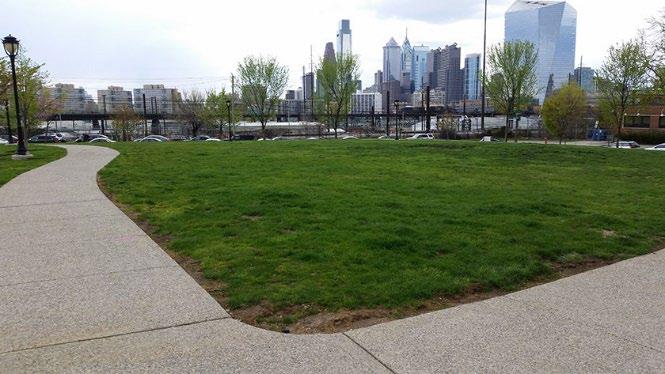
Figure 4.6.3.1 Example of Pavement Disconnection (Source:
4.6.4 Use Permeable Pavement Systems
Use Permeable Pavement Systems
Description: Permeable pavement allows rainwater to percolate into the base layer below the concrete or paver. When used instead of impervious pavement, these surfaces can mimic the natural hydrology of the area it covers (Figure 4.6.4.1). With proper design, these surfaces can manage stormwater from other areas.
Planning and Design Activities:
Green Infrastructure-SCM
Key Benefits:
Mimics natural hydrology during small storms
Provides a multi-functional surface useful for both transportation and stormwater management
Can provide an upscale and unique aesthetic
May reduce the size of stormwater infrastructure
The following considerations are important when contemplating the use of permeable pavement systems in a site design.
4.6.4.1 Water flowing Through Pervious Concrete (Source: National Ready Mixed Concrete Association)
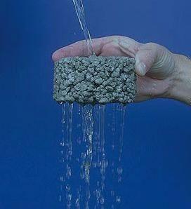
Consider the use of permeable pavements (e.g. pervious concrete, pervious pavers, porous asphalt, etc.) in parking areas and lowuse/light-load driving areas. However, some paver systems may be suitable for higher use/higher load areas. Consult local concrete/paver vendors for more information on paver types, use, and load criteria.
These surfaces are suitable and encouraged for use as driveway surfaces on single-family residential (SFR) lots. However, they cannot be claimed as an SCM for compliance with stormwater management rules in the cities of Johnson City, Kingsport, Bristol, or Elizabethton when used in this manner. This is due to difficulties inherent in oversight of regulated stormwater SCMs on SFR properties. These surfaces can be used in residential common areas, such as amenity area parking lots.
Permeable pavement systems must be designed in keeping with the use and load specifications for the material being used and the design specifications provided in Chapter 5, Section 5.8.
Permeable pavement systems are highly versatile in terms of color and design (Figure 4.6.4.2).
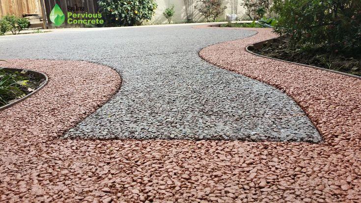
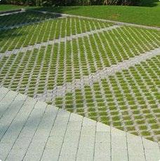
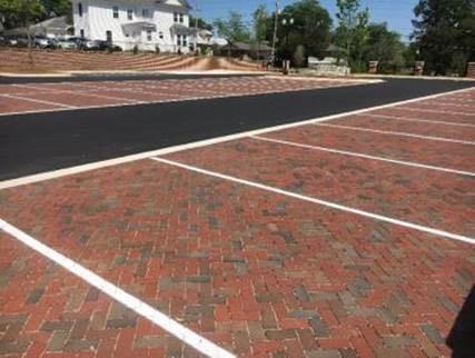
Figure 4.6.4.2 Examples of Design Versatility of Permeable Pavement Systems
Figure
Sources: Left, Bay Area Pervious Concrete; Middle, multiple pervious surfaces shown, source unknown; Right, City of Auburn AL
4.7 Use of Natural Features and Preserved Areas
After the layout of the future development is created, site designers should look at the natural areas and resources that have been preserved (or restored) as possible areas for stormwater management. There are a number of ways to do this, as indicated by the LID design practices listed below and described in the sections that follow.
Section 4.7.1 Use Undisturbed Areas and Stream/Shore Buffers for infiltration from small impervious areas, as filters for overland flow, or areas where other SCMs can be located.
Section 4.7.2 Use Natural Drainageways and Vegetated Swales for stormwater conveyance through the property.
Section 4.7.3 Connect to Parks/Greenways and Provide Pocket Parks to enhance onsite green spaces by connecting them to public use areas or create hydrologically mimicking amenities within the development.
Section 4.7.4 Create Multi-Functional Spaces describes how stormwater SCMs can serve multiple site purposes with thoughtful design.

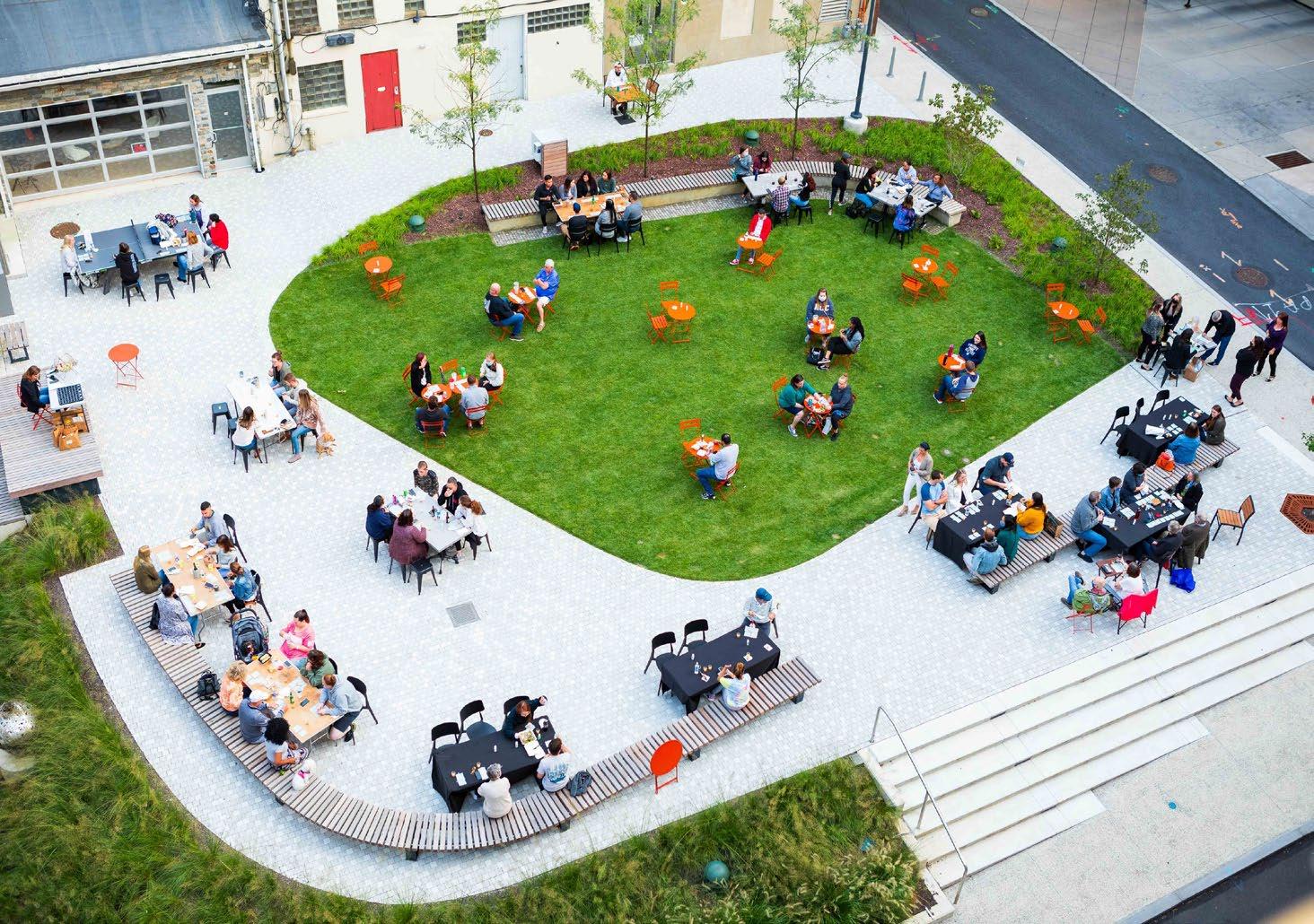
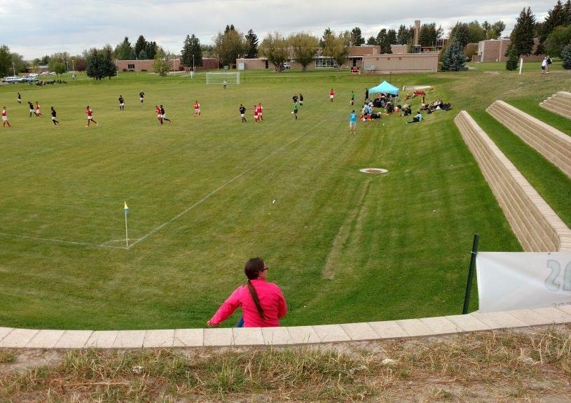
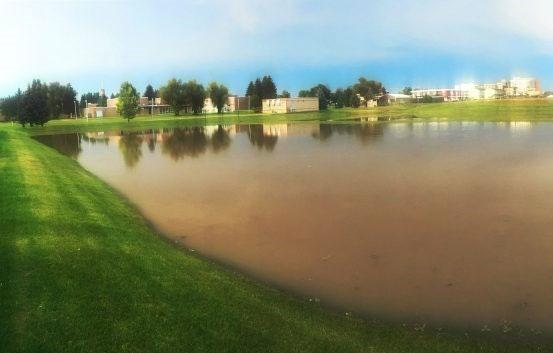
Figure 4.7.1 Examples of “Use of Natural Features and Preserved Areas” LID Design Practices
(Top left) Green way connection to a multi-family residential development provides public amenity to residents, City of Sacramento, CA; (Right): A pocket park in Allentown, PA, Land Collective; (Bottom) Detention basin used as recreational fields in Great Falls, MT. Picture on left shows the basin when dry and the one on the right shows it after a storm event. TDH Engineering.
Same detention basin
4.7.1
Use of Undisturbed Areas and Stream/Shore Buffers
Use Undisturbed Areas and Stream/Shore Buffers
Description: With proper design, preserved stream or shoreline buffers and other undisturbed areas on a development can provide areas for natural infiltration and filtration of stormwater runoff.
Planning and Design Activities:
LID Design Practice
Key Benefits:
Provides multiple environmental benefits (stormwater and stream/shore stability, shading, etc.)
May reduce the size of stormwater infrastructure
The following considerations are important when contemplating the use of preserved areas or stream/shoreline buffers for stormwater management.
This LID practice relies on natural infiltration, not GI-SCMs engineered to infiltration. Group 1 and 2 GI-SCMs that operate via infiltration/biofiltration cannot be located in stream/shore buffers and floodplains. Select only those natural areas that will remain preserved and undisturbed for the life of the development. If there is a chance of disturbance in the future (e.g., due to the construction of the next phase of a development), the area cannot be used to accept and treat surface runoff.
The preserved area, if not previously disturbed, should not disturbed during clearing, grading, and development construction, in keeping with the State of Tennessee Construction General Permit (TN-CGP) and local government restrictions on stream buffers during and after construction. If already disturbed, soil restoration is required to eliminate compaction and improve soil permeability. Consult a Tennessee licensed Soil Scientist, Registered Landscape Architect, or local agricultural extension for guidance. Furthermore, the area should undergo restoration to foster the growth of dense, healthy, and diverse vegetation over time Managed turf is not acceptable vegetation for these areas. See Figure 4.7.1.1 for an example of stream buffer plant design and diversity.
This LID practice is suitable only for small impervious areas that can safely be discharged to the preserved area as sheet flow. Criteria are as follows.
• The maximum contributing flow path of the impervious pavement is 50 feet. The length and width of overland flow over the preserved area must be greater than, or equal to, the length and width of the contributing flow path over the impervious area.
• The slopes of the impervious area must be less than 5%.
• No more than 1,000 ft2 of pavement may discharge to the preserved area at a single location.
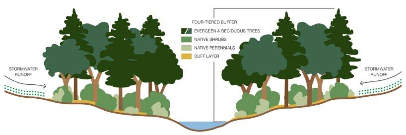
Figure 4.7.1.1 Graphic Showing Vegetation in a Tiered Stream Buffer (Source: The LID Certification TM System)
4.7.2 Use Natural Drainageways and Vegetated Swales
Use Natural Drainageways and Vegetated Swales
Description: Preserved natural drainageways, constructed grass channels, and vegetated swales can provide an inexpensive means for stormwater conveyance within the boundaries of the land development. They are less hydraulically efficient than curb and gutter, pipes, and lined channels, resulting in longer travel times, which reduces pollutants and temperatures and lowers peak discharges.
Planning and Design Activities:
LID Design Practice
Key Benefits:
Slows, filters, and cools stormwater, especially for small, frequent storm events
Can be combined with other LID design practices to enhance hydrologic mimicry
Provides natural character
Lower construction and maintenance costs
The following criteria must be considered when using natural drainageways and vegetated swales for onsite stormwater conveyance. Stormwater must discharge to the drainageway or swale in a non-erosive manner. Where discharges to the feature are concentrated/channelized flow, energy dissipation must be provided (refer to Chapter 5, Section 5.16).
A vegetated swale alone is not considered an SCM for water quality treatment. It can be used for pretreatment or simply as a stormwater conveyance feature. However, if water quality treatment is needed, consider the use of a dry enhanced swale SCM (Chapter 5, Sections 5.3) instead of a vegetated swale. Dry enhanced swales can provide both water quality treatment and stormwater conveyance.
Vegetated swales shall be designed as follows:
A vegetated swale must be designed to accommodate the peak flow for the water quality design storm (Qwq), and the 2year, 24-hour design storm without eroding (see Chapter 3 for more information on the Qwq). Larger flows must be accommodated by the swale as required by the local government for onsite stormwater conveyance
The maximum flow velocity in the vegetated swale must be less than or equal to one foot per second (1.0 ft/s).
The bottom width shall be a maximum of 6 feet. If a larger channel is needed to accommodate onsite flows, a compound cross-section (i.e., a benched channel) is required.
Swale side slopes shall be 3:1 (horizontal : vertical) or flatter.
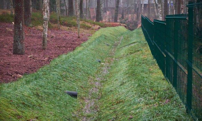

The swale should be entirely vegetated with dense, deep-rooted plants that can withstand occasional inundation and water flows. Managed turf is suitable, but tall, dense, non-woody plants are preferred. Areas of bare soil or nonvegetated ground cover (e.g., mulch, river rock, etc.) are not permitted.
Figure 4.7.2.1 Examples of Vegetated Swales
Source: WAYPOINT Property Inspection, LLC
Source: Ft. Wayne, IN
4.7.3 Connect to Parks/Greenways and Provide Pocket Parks
Connect to Parks/Greenways & Provide Pocket Parks LID Design Practice
Description: Preserve open space and enhance development amenities by connecting private land developments with city greenways or creating privatelyowned “pocket parks” within a development.
Key Benefits:
Mimics natural hydrology during small storms
Provides multi-functional spaces, useful as both landscape features and private space amenities
Can improve property aesthetic and value
Planning and Design Activities – Park/Greenway Connections:
Connections to public use areas can be considered amenities to the residents or businesses within land developments in close proximity to these areas. The connection can provide access to a larger green space for recreation, picnicking, or exercise. The following considerations are important when contemplating a park/greenway connection or pocket park.
Consult with the local planning and zoning departments to remove obstacles to the connection of a private land development to a public park or greenway.
Although green space within the land development is preferred from a stormwater management perspective, a park/greenway connection does not have to involve a park-like setting. It can simply consist of a connection via a pedestrian/bike path, trail, or street/parking access.
Consider the use of signs to identify where the public park/greenway end and private property begins.
Planning and Design Activities– Private Pocket Parks:
A pocket park is a small outdoor space, usually no more than ¼ of an acre, located in an urban or suburban area for people to gather, relax, and enjoy the outdoors (Figure 4.7.3.1). In a private setting, they are amenities for the owners/users of the property where they are located. Successful pocket parks are accessible, engaging, comfortable, and sociable spaces.
Good locations for pocket parks are small, disturbed, open spaces that are left after the site layout and disturbance areas are known. They can also be integrated with a green infrastructure SCM, such as a bioretention area. Consider adding signs that educate park users on the SCM and advise them to enjoy, but not enter, it.
In commercial/industrial settings, the park should be accessible by foot. In a neighborhood, it should be accessible by foot and bicycle.
Consult a Landscape Architect for park location selection, design, and vegetation.
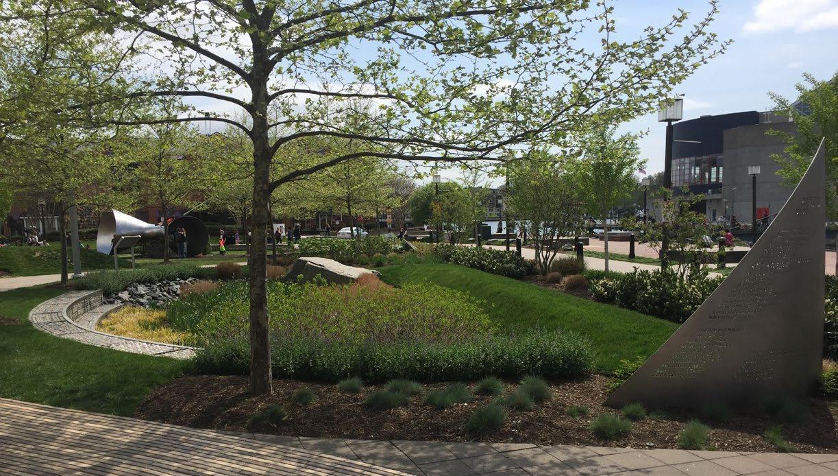
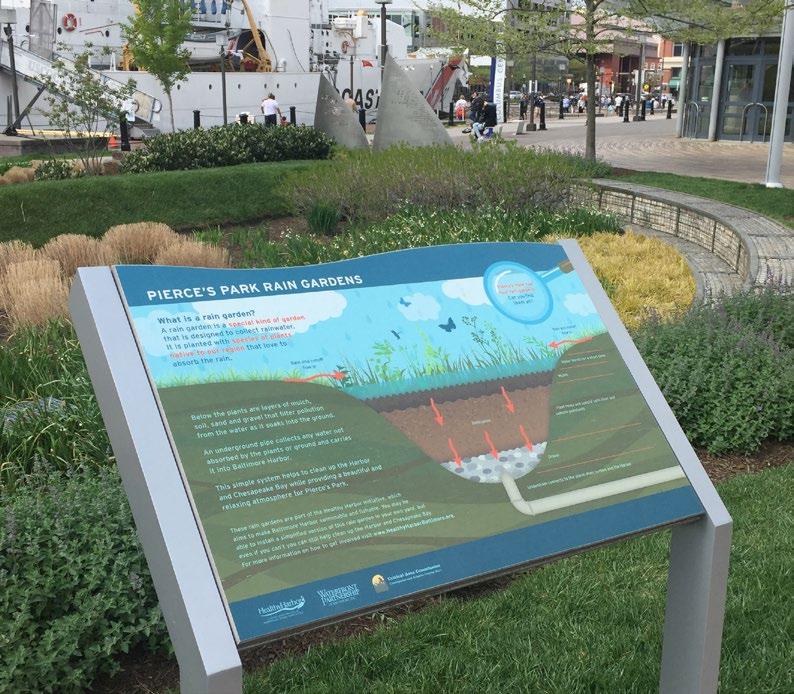
Figure 4.7.3.1 Example of a Pocket Park in Baltimore, MD with an Integrated Bioretention SCM
Source: WSP
4.7.4 Provide Multifunctional Landscaping
Provide Multi-Functional Landscaping LID Design Practice
Description: Some SCMs can serve other functions on a land development. Identifying and taking advantage of these opportunities may save land, since two necessary functions occupy the same space. It can also reduce both construction and maintenance costs and provide additional value to the property for future property owners.
Discussion:
Key Benefits:
Provides multi-functional spaces, useful for stormwater management and other functions
May reduce costs for BMP construction and maintenance
May reduce the size of stormwater infrastructure
Some LID design practices and stormwater control measures (both green infrastructure-SMCs and traditional SCMs) can provide site functions beyond stormwater management. Examples include:
LID design practices and SCMs can meet both stormwater rules and land development landscape requirements
Recreational fields that double as stormwater detention ponds or emergency flood storage areas
Pedestrian walking trail constructed within preserved natural space or along preserved stream corridors
Planning and Design Activities:
Urban bioretention SCM that doubles as a landscaped parking lot island
Permeable/pervious surfaces provide both stormwater control and parking/drive surfaces
LID practices that double as a pocket park
The following considerations are important when contemplating the use of stormwater features as multi-functional spaces.
The local government places the responsibility for the inspection and maintenance of all SCMs on the property owner. This must be kept in mind when designing a multi-functional space. The SCM should be designed to protect the stormwater functionality and accessibility for inspection and maintenance.
Consult the local government to determine landscape requirements for property developments. These requirements should not conflict with the vegetation requirements for SCMs.
SCM protection is especially important when it provides functions to property users beyond stormwater management. Permanent protection measures can be active (such as a physical fence) or passive (such as a walkway and bench) that direct pedestrians around or between SCMs. Often, they can be integrated aesthetically into the SCM design. Consult the SCM design specifications in Chapter 5 for more information.
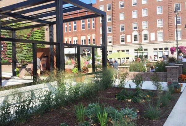
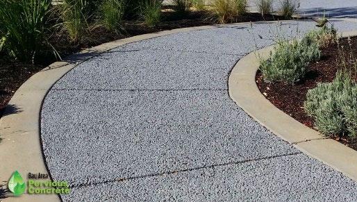
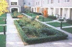

Figure 4.7.4.1 Examples of Multi-Functional LID Design Practices and SCMs
Left: Rain gardens and cisterns are featured in this urban pocket park (Snyder & Assoc.); Middle: Pervious concrete sidewalk (Bay Area Pervious Concrete); Right: Urban bioretention provides a pleasant landscape for townhomes (knowyourh2o.com)
4.8 References
ARC. Georgia Stormwater Management Manual Volume 2 Technical Handbook, 2016 Edition. Atlanta Regional Commission, 2016
City of Birmingham AL. Post-Construction Stormwater Design Manual. March 2019.
Ebrahimian Ali, Bridget Wadzuk, and Robert Traver. Evapotranspiration in green stormwater infrastructure systems. Department of Civil and Environmental Engineering, Villanova University, Villanova PA. June 27, 2019
Philadelphia Water Department. Philadelphia Stormwater Management Guidance Manual, Version 3.2. October 2020.
USEPA Low Impact Development Center. Low Impact Development (LID). A Literature Review. EPA-841-B-00-005, October 2000.
Table of Contents
CHAPTER 5: SCM DESIGN SPECIFICATIONS
5.8.10
5.11.11
5.12.5
5.17.2
5.1 Bioretention Area
design specification
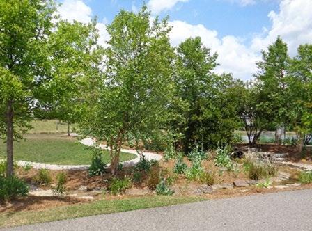
Overview
SCM Group(s): 1 & 2
Bioretention areas are low impact development stormwater control measures (SCMs) with vegetated, shallow depressions used to capture and filter stormwater runoff through an engineered soil mix. Stormwater is either infiltrated into the subsoil or exfiltrated through an underdrain. This SCM is becoming more popular because of its versatility in location, configuration, size, and landscape.
ADVANTAGES/BENEFITS
Considered a green infrastructure SCM
Reduces pollutant discharges and runoff volume
Can be designed to address small, localized flooding issues
Enhances site aesthetics and habitat availability
DISADVANTAGES/LIMITATIONS
Not often suitable for detention of the 2-yr storm and larger events
Highly sensitive to poor construction erosion and sediment control practices; cannot be used as a sediment trap/basin during construction
LOCATION, SIZING, & COMPONENTS
An underdrain and internal water storage is required for most applications
Not appropriate for slopes greater than 20%
The amount of impervious surface area draining to the bioretention SCM cannot exceed 20 times the bioretention SCM surface area
Minimum 2-foot separation from seasonally high-water table
Runoff pretreatment is required at all inlets
Energy dissipation is required at all inlets
LONG-TERM PROTECTION
Primary concerns are plant damage and soil compaction
Protect from entry by vehicles and heavy equipment
LONG-TERM MAINTENANCE
Primary routine maintenance activities will be inlet, pretreatment device, plant bed cleaning, and plant care (e.g., weeding, pruning, mulching, leaf and landscape debris removal, plant replacement)
Consider permanent signs to dissuade entry and use of SCM as a pet relief area if SCM is near a pedestrian area
Select plants that can withstand occasional short-term inundation
Provide trash cans and pet waste stations in the drainage area
Northeast Tennessee Water Quality SCM Manual
5.1.1 General Description
Bioretention areas (sometimes called “rain gardens”) are SCMs that capture and infiltrate (or temporarily store) the water quality treatment volume (WQv) using soils and vegetation in shallow, landscaped basins. If the native soils readily allow infiltration, the captured stormwater will exit the basin and soak into the surrounding soil. If not, the filtered stormwater drains into an underdrain then discharges to the onsite stormwater drainage system. In northeast Tennessee, the lack of soils with appropriate infiltration rates and a high presence of karst terrain are factors that will influence the design of most bioretention areas. An underdrain will be required in most applications to facilitate proper operation and prevent sinkhole formation More detail on soil infiltration rate criteria and other infiltration feasibility factors is provided later in this design specification.
5.1.2 Design Applications
Bioretention areas are highly versatile SCMs appropriate for numerous design applications They can be used for all soil types since runoff simply percolates through an engineered soil mix and can be returned to the stormwater system via an underdrain if the infiltration rate of the underlying soils is low. The most important design factor to consider when designing this SCM is the scale at which it will be applied. There are few limits on their geometry which means they can be sized to fit into tight site layouts. Bioretention areas are often used at commercial, institutional, and residential sites in spaces that are traditionally pervious and landscaped, such as parking lot islands and buffer areas (see Figure 5.1.2.1). With proper design and maintenance, this SCM can also be used in highly impervious or space-constrained, high-traffic areas.
Examples of Bioretention Area Applications
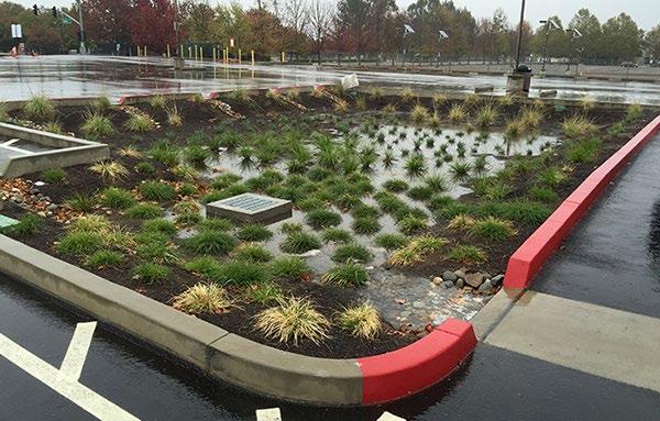
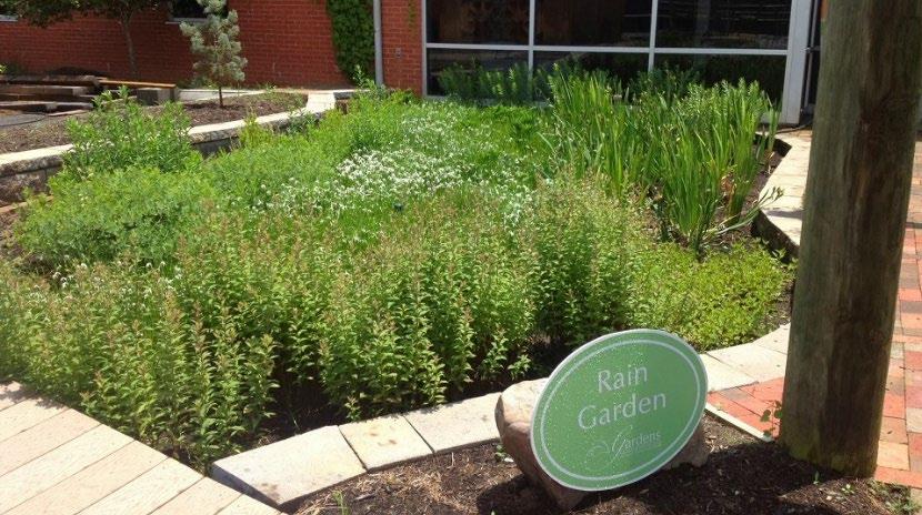
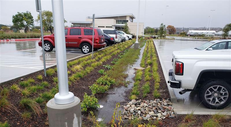
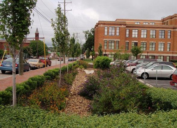
Figure
5.1.2.1
Location and photo source: (top left) Sacramento State Campus, Sacramento State Office of Water Programs; (top right) location unknown, The Nature Conservancy; (bottom right) Metro Water Services parking lot in Nashville TN; (bottom left) University of Tennessee Gardens, Univ. of TN campus in Knoxville, TN
Typical locations for bioretention areas include the following:
Parking lot islands Bioretention areas can be sited as linear features (between parking space rows) or within parking lot islands. Flow into the bioretention areas is achieved with sheet flow over flush pavement edges (with the SCM), or through curb cuts if curbing around these areas is required by local government parking lot design requirements. Curb cuts are more prone to blockage, clogging, and erosion and thus have a minimum opening width of 18 inches. For flush pavement edges between rows of parking stalls, curb blocks are highly recommended to prevent inadvertent vehicle entry into the SCM. An apron of dense turf or cobbles around the edge of the area functions as a filter strip to provide pretreatment.
Parking lot edge. Small parking lots can be graded so that flows reach a flush pavement edge or curb cut before reaching catch basins or storm drain inlets. The turf at the edge of the parking lot functions as a filter strip to provide pretreatment for the bioretention practice. The depression for the bioretention area is located in the pervious area adjacent to the parking lot.
Courtyards. Stormwater collected in a storm drain system or roof leaders can be directed to courtyards or other pervious areas on site where bioretention can be installed.
Unused pervious areas on a site. Bioretention areas can be applied in unused pervious areas on a site to provide both stormwater management and landscaping. Storm flows can be redirected from a storm drainpipe to discharge into the area.
Dry Extended Detention (ED) basin. A bioretention area can be located on an upper shelf of an extended detention basin, after the sediment forebay, in order to boost treatment. A bypass or diverter must be implemented to send large flows directly into the basin. See Section 5.4 (Dry Extended Detention Basin) for more information on design of a dry ED basin.
Retrofitting. Numerous options are available to retrofit bioretention areas in the urban landscape. These are described more fully in Section 5.13 (Urban Bioretention)
5.1.3 SCM Suitability
Use Table 5.1.3.1 to determine if a bioretention area is suitable for the application being considered.
Table 5.1.3.1 Bioretention Suitability Factors
Stormwater Quality Treatment Bioretention areas designed in keeping with the specifications established herein will satisfy local government stormwater quality treatment standards.
Channel Protection
It may be possible to size a bioretention area to provide channel protection (extended detention of the 1-year, 24-hour storm) for smaller sites. However, this is unnecessary for bioretention areas that discharge to another control that is designed to provide channel protection (like a detention basin).
For larger sites or where the WQv is diverted to the bioretention area (an offline design configuration), channel protection must be provided by another control, such as a dry ED basin.
Detention
Bioretention areas are generally not suitable for peak discharge (detention) control, even for small design storms (the 2-year event). The bioretention area must be designed to bypass these flows. Bioretention areas can be helpful in addressing small, limited, onsite drainage issues when designed with additional storage capacity for volumes higher than the WQv. This is done by providing additional internal water storage (IWS) When allowed, IWS shall be designed in accordance with Section 5.15 (Underdrains & Internal Water Storage).
Northeast Tennessee Water Quality
Factor Suitability
Pollutant Treatment
Capability
Treatment of Waste and Other Pollutants
Bioretention areas can be used to address following common stormwater pollutants)1:
Suitability by Land Use
1 Georgia Stormwater Management Manual, Volume 2 Technical Handbook, 2016 Edition.
*Cadmium, copper, lead, and zinc
Bioretention areas shall not be used to treat wastes and other pollutants, many types of which are listed below, should they be present in the contributing drainage area to the bioretention area:
Construction sediment/waste
Landscape storage or waste
Sewage, pet, and livestock waste
Medical waste
Household & commercial wastes
Hazardous wastes
•
Gasoline, motor oils, greases, and other petroleum-based products
Fats, oils & grease (from food preparation)
Pesticides, fertilizers, herbicides
Other byproducts and waste materials expected, based on the property’s land use
Privately owned bioretention SCMs are not allowed in the public right-of-way.
General suitability criteria by land-use type are as follows. See Chapter 3 (Standards, Methods, and SCM Selection) for more information.
Commercial Industrial Private Roadways Single Family Residential Multi-Family Residential Yes Yes (with liner) Yes Common Areas Only
*These policies do not preclude the use of bioretention areas on individually owned single family or multi-family residential lots. However, bioretention areas placed on residential lots will not be considered by the local government as suitable for compliance with local government stormwater management requirements due to the inherent difficulties in oversight and enforcement of long -term protection and maintenance requirements on residential lots
5.1.4 SCM Location Requirements
Location constraints for bioretention areas are provided in Table 5.1.4.1.
Table 5.1.4.1 Bioretention Area Location Requirements
Physical Element
Minimum SCM Setbacks
Requirement
Minimum setbacks, measured from the edge of the bioretention area, are as follows:
Building foundations:
Offline configuration: 10 feet from a building’s foundation, if positioned downslope of the building; 30 feet from buildings that are downslope.
Online configuration: safe passage of the 100 -year storm event is required; therefore, the distance of the edge of the SCM from a building’s foundation shall be determined based on the expected extent of flooding around the SCM for the 100-year event.
100 feet from private water supply wells.
200 feet from public water supply reservoirs (measured from edge of water)
1200 feet from public water supply wells.
100 feet from underground septic systems.
Physical Element
Flow Avoidance
Utility Avoidance
Requirement
At least 5 feet down gradient from underground utility lines.
Bioretention areas shall not be located where it will receive continuous or dry weather inflows from springs, seeps, sump pumps, wash stations, or other sources.
Bioretention areas shall not be located above underground dry utility lines (electric, cable, and telephone) and water/wastewater infrastructure.
Design professionals must consult the local utility to determine the horizontal and vertical clearance required between SCMs and dry and wet utility lines.
5.1.5 Design Requirements
Figures 5.1.5.1a and 5.1.5.1b are general schematics of a bioretention area with and without an underdrain An alternate underdrain design is shown in Section 5.15 (Underdrain & Internal Water Storage Design Specification). After the schematics, Tables 5.1.5.1 and 5.1.5.2 provide the minimum standards and design specifications for the design of bioretention areas and their contributing drainage areas. The criteria provided in the tables are applicable to the design of both Group 1 and Group 2 bioretention areas unless stated otherwise
Figure 5.1.5.1a Schematic of a Bioretention Area Without an Underdrain (Group 1 SCM)
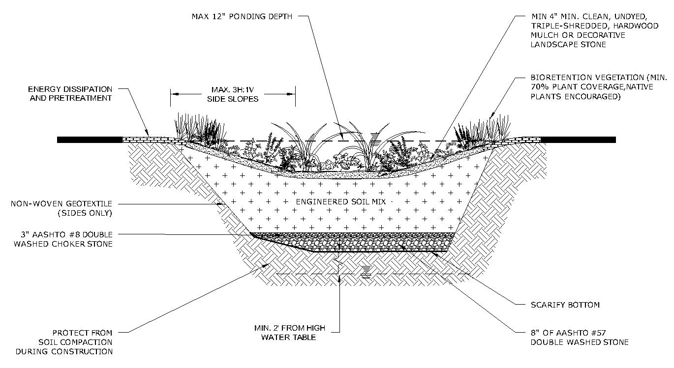
5.1. 5.1b Schematic of a Bioretention Area with an Underdrain and IWS (Group 2 SCM)
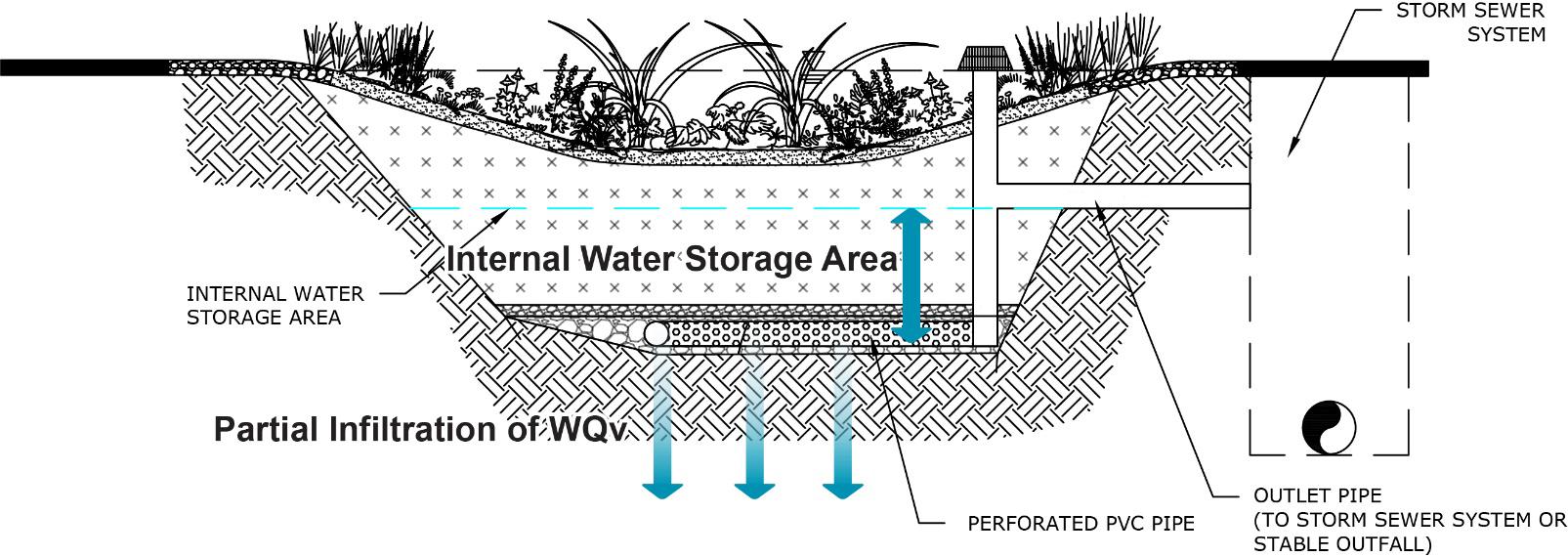
Table 5.1.5.1 Design Specifications for the Contributing Drainage Area
Design
Drainage Area
Slope
Controls for Waste & Other Pollutants
Specification(s)
Maximum contributing drainage area (CDA) = 5 acres; 0.5 to 2.0 acres is preferred
Contributing drainage areas greater than 5 acres can be divided into multiple areas, each drainage area draining to a separate bioretention area or another SCM.
Maximum slope = 20%; 5% is preferred.
Energy dissipation techniques upstream of the inlets must be used for CDA slopes greater than 5% to ensure WQv flow will not bypass the inlets and have a maximum inflow velocity of 5 ft/sec.
Terracing or inlet controls may be used to slow runoff velocities.
Bioretention areas are not allowed in areas where slopes exceed 20%.
Appropriate controls shall be included in the design of the contributing drainage area to the SCM to address any wastes and o ther pollutants (see Table 5.1.3.1 above) that are expected on the property after construction Use the proposed land use as a guide to determine appropriate controls. Examples of such controls include, but are not limited to, dumpsters, trash cans, covered materials/waste storage areas, covered materials transfer areas, oil and grease waste controls, and pet waste stations
Table 5.1.5.2 Design Specifications for the Bioretention Area
Design Element
Infiltration Feasibility Policies
Specification(s)
Bioretention areas shall be designed as a Group 2 SCM (i.e., with an underdrain and internal water storage) unless ALL the following conditions are met:
The SCM will be constructed in uncompacted, native soil that has an infiltration rate between 0.5 and 11 inches/hour, and these soil conditions can be maintained throughout construction of the land development.
Sufficient protection measures to prevent soil compaction within and around the bioretention area after construction are included in the design
The development and the SCM meets all infiltration feasibility factors established in the Infiltration Feasibility Form provided in Appendix C (Infiltration Feasibility Form).
Figure
Northeast Tennessee Water Quality SCM Manual
Design Element
Class V Injection Well Permits
Water Quality
Volume (WQv)
Use in a Water Quality Treatment Train
Offline and Online Design Configuration
Specification(s)
Infiltration tests are required for Group 1 SCMs before and after bioretention area construction
See Appendix F (Policies for Soil Infiltration Tests & Soil Borings) for infiltration test requirements. Additional geotechnical information may be required by the local government.
Although unlikely, bioretention areas may be subject to a Class V Injection Well Permit pursuant to Tennessee Department of Environment and Conservation (TDEC) rule 0400-45-06-.06. This permit may be avoided by ensuring the bioretention area excavation is wider than it is deep and using a design configuration with an underdrain. Regardless, the requirement for a permit is determined by TDEC, not the local government. When a permit is required, a copy must be provided to the local government prior to, or with, the su bmission of the Water Quality Management Plan.
The water quality rainfall depths (P) for determination of WQv are as follows:
Bioretention areas without an underdrain (Group 1 SCM): P = 1.0 inch
Bioretention areas with an underdrain (Group 2 SCM): P = 1.25 inches. Acceptable methods to determine WQv are presented in Chapter 3 (Standards, Methods, and SCM Selection).
Bioretention areas that cannot treat the entire WQv for its contributing drainage area must be used in a treatment train or replaced with an alternate SCM that can treat the entire WQv.
If the bioretention area cannot manage the entire WQv for its contributing drainage area, it must be placed in a treatment train with another SCM. See Chapter 3, Section 3.2.4 for treatment train policies and calculations.
An offline configuration is the preferred design configuration for most bioretention area applications as they are designed and constructed away from the main flow path for the drainage area, thus avoiding large flood flows. A flow splitter, diversion structure, or other means is used upstream of the bioretention area’s inlets to redirect the bioretention area’s design volume (typically this will be the WQv) from the main flow path to the SCM while still allowing larger flows to remain in the main flow path. The structure shall include a low-flow orifice, weir, or other hydraulic structure, sized to pass the peak discharge of the design volume (typically this will be the water quality peak discharge, Qwq) to the bioretention area. The design procedure (see Table 5.1.6.1) provides the method required for diversion structure sizing.
An online configuration is designed and constructed so the main flow path for the drainage area passes through the bioretention area. This creates a high potential for frequent sediment deposition in the engineered soil mix and corresponding need for remedial maintenance. Thus, an online bioretention area is permissible only for drainage areas that are 100% impervious and have low potential for sediment and debris loads, such as drainage from a small building rooftop. Regardless of design configuration (offline or online), bioretention areas shall always be located upstream of other SCMs (e.g., detention basins designed for flood control, SCMs in a water quality treatment train, etc.).
Flow regulators (flow splitters, diversion structures, and overflow structures) shall be designed in keeping with Section 5.17 (Overflow Controls).
The entire bioretention area must be accessible for maintenance without requiring the entry of vehicles or heavy equipment in the bioretention area.
Maintenance Access and Easement
A maintenance easement to (and including) the bioretention area must be provided from a public roadway. The easement must be free of permanently affixed obstructions (e.g., trees, pools, fences without gates, permanent signs, etc.) to allow maintenance vehicles and equipment to safely pass.
Design Element
Inlets, Energy Dissipation, & Pretreatment
Surface Area and Geometry
Side Slopes
Ponding Depth
Minimum Depth to Water Table
Minimum Hydraulic Head
Drawdown Time
Specification(s)
Maximum stormwater entry velocity = 5 ft/sec
Stormwater shall enter the bioretention area as sheet or shallow concentrated flow. Energy dissipation measures, such as vegetated buffer strips or rock aprons shall be provided. These measures may also provide stormwater pretreatment
Pretreatment is required within or immediately after each inlet to remove gross solids, trash, and sediment from stormwater prior to flowing into the main treatment area. Guidance is as follows:
Vegetated filter strips and gentle side slopes of dense grass are suitable pretreatment measures for lateral, non-concentrated inflows. Rock aprons or other methods may be preferred for more concentrated inflows. Pretreatment options and design specifications are provided in Section 5.16 (Inlets, Energy Dissipation, and Pretreatment Measures).
Swales that will receive direct concentrated stormwater may require a 6-inch drop to a pea gravel diaphragm flow spreader at the upstream end of the control to slow and spread runoff entering the swale.
Consider screens, grates, baffles, or other pretreatment measures for debris capture in areas where high amounts of floatables (litter, trash, etc.) is expected.
Recommended minimum surface area = 3% to 5% of the CDA.
Stormwater flowing into the bioretention area must be distributed evenly across its entire surface area. Ensure the planting bed/engineer soil mix are not bypassed or short- circuited (e.g., inlets or curb cuts that are very close to outlet structures, or incoming flow diverted immediately to the underdrain).
Side slopes = 1:1 or flatter, except when one or more vertical side walls are necessary.
For bioretention areas near pavement or in space-constrained areas, a drop curb design or a precast structure can be used to create a stable, vertical side wall. Safety precautions, such as railing, fencing, walls, grates, etc. shall be included in the design for vertical drops exceeding 6 inches.
If three vertical sides or greater are needed, design professionals must use Section 5.13 (Urban Bioretention).
Maximum surface ponding depth = 12 inches.
Minimum separation distance (bottom of excavation to seasonally high-water table) = 2 feet
Soil borings shall be used to determine the seasonally high-water table. See Appendix F (Policies for Soil Infiltration Tests & Soil Borings) for soil boring requirements.
Minimum hydraulic head = 3 feet
The hydraulic head is the difference in the inflow elevation, including the design ponding depth, to the outflow elevation at the underdrain invert elevation or bottom of SCM at its downstream end.
Bioretention areas without an underdrain (Group 1 SCM):
Maximum water ponding time = 12 hours
The WQv shall exfiltrate the bioretention area to at least 2 feet below the bottom of the area within 48 hours.
Bioretention areas with an underdrain (Group 2 SCM):
The WQv, excluding water contained in the internal water storage (IWS) area, shall fully discharge from the underdrain within 48 hours.
Northeast Tennessee Water Quality SCM Manual
Design Element
Overflow Structure
Specification(s)
An overflow structure that safely passes runoff that exceeds the design volume (typically this will be the WQv) must be included in the design to prevent overfilling the SCM and flooding in adjacent areas. Small, offline bioretention areas may be excepted from this requirement depending on situation.
The overflow inlet is typically a yard drain catch basin (with suitable debris/trash rack), though any number of conventional systems could be used. It must be set at the maximum ponding elevation (i.e., no more than 12 inches above the mulch layer).
The overflow structure shall bypass the underdrain and discharge to the outlet pipe/channel for the bioretention area (e.g., typically an onsite stormwater conveyance system or stabilized watercourse). Discharges to a channel must be non-erosive (maximum of 5 ft/sec).
See additional requirements for bypass/overflow structures in the online configuration row of this table (below), and guidance provided in Section 5.17 (Overflow Controls).
The remaining rows specify the subsurface layers of the SCM, starting at the bottom.
Limit the excavation to the width and depth specified in the design.
In-situ Soil
Liner Layer(s)
If an impermeable liner is not included in the design, scarify the bottom of the excavation to a minimum depth of 6 inches by raking, disking, or tilling prior to placement of SCM layers. The sidewalls shall be uniform with no voids and scarified prior to backfilling.
Trim all large roots on the sides and bottom of the excavation before layers are placed. Place layers in a way that does not cause compaction of the underlying in-situ soil.
For most applications, a non-woven geotextile fabric having a flow rate greater than 110 gal/min/ft2 shall be installed on the sides only of the excavation to maintain separation between the in-situ soil and bioretention area layers.
Where karst terrain is a concern or soil contaminants are known or suspected, place an impermeable liner on the sides and bottom of the excavation.
Bioretention areas without an underdrain (Group 1 SCM): 8-inch layer of AASHTO #57 stone (double washed).
Bioretention areas with an underdrain (Group 2 SCM): see Section 5.15 (Underdrain & Internal Water Storage)
Bottom Stone Layer
Upturned elbow underdrain: the bottom stone layer is the same as the “stone jacket” layer specified for the underdrain.
Elevated underdrain: the bottom stone layer is the same as the internal water storage (IWS) layer specified for the underdrain
Underdrains & Internal Water Storage (IWS)
Stone Choker Layer
Engineered Soil Mix Layer
Bioretention areas without an underdrain (Group 1 SCM): An underdrain with IWS is not included in the SCM.
Bioretention areas with an underdrain (Group 2 SCM): An underdrain and a minimum of 12 inches of internal water storage must be provided. See Section 5.15 (Underdrain & Internal Water Storage) for specifications. See also Figures 5.1.5.1a and 5.1.5.1b.
Bioretention areas without an underdrain (Group 1 SCM): 3-inch layer of double-washed AASHTO #8 stone or AASHTO #89 pea gravel placed on the bottom stone layer.
Bioretention areas with an underdrain (Group 2 SCM): see Section 5.15 (Underdrain & Internal Water Storage)
Minimum depth of the engineered soil mix layer = 18 inches
Beyond the minimum, the design depth is determined by the design volume (typically this will be the WQv), the geometry of the bioretention cell, and plant needs for establishment and long-term root growth.
Northeast Tennessee Water Quality
Design Element
Specification(s)
The engineered soil mix shall be a homogenous mix and meet the standards in the following two tables to provide adequate infiltration, nutrient uptake, and plant support.
Material
Medium to coarse washed sand: 70-85%
Particle size: 0.050 to 2.0 mm
Silt + clay 10 to 20%, with clay content less than 10%
Clean, fine soil:
Engineered Soil Mix Layer (continued)
Clay particle size: < 0.002 mm
Silt particle size: 0.002 to 0.050 mm
Organic Matter 5 to 8%
*Animal or poultry manure, at any stage of composition, shall not be used for organic matter content
AASHTO T88 Standard Method of Test for Particle Size Analysis of Soils
AASHTO T194 Standard Method of Test for Determination of Organic Matter in Soils
pH 5.5 to 7.5
Magnesium
Phosphorus* (as phosphate P205)
Potassium (K20)
Soluble Salts
Minimum 32 parts per million (ppm)
Maximum 60 ppm as plant available phosphorus
Minimum 78 ppm
Maximum 500 ppm
The volume of engineered soil mix specified and placed shall be based on 110% of the required volume for the SCM to account for settling just after mix placement in the SCM.
Assume an infiltration rate of 2 inches per hour for the engineered soil mix when determining the ponding depth and media depth.
Mulch Layer See Section 5.1.7 below, titled Vegetation Design Specifications, for mulch standards.
Planting Bed See Section 5.1.7 below, titled Vegetation Design Specifications, for planting bed standards.
5.1.6 Design Procedure
Table 5.1 6.1 provides the design procedure for a bioretention area.
Table 5.1.6.1 Design Procedure Step
Evaluate bioretention area feasibility.
Step 1
Use the feasibility criteria provided in Tables 5.1.3.1 and 5.1.4.1 to determine if a bioretention area is feasible for the selected location on the land development site. Consider especially whether it is appropriate for the proposed development based on the intended land use of the property, the maintenance burden, and assumptions or knowledge of how the property owner(s) will care for the bioretention area after construction (e.g., self-maintenance, property/facilities management maintenance, landscape contractor). If possible, include the property owner(s) in SCM selection since they will be responsible for maintenance.
Northeast
Step Design Activity
If a bioretention area is determined to be feasible and appropriate for the proposed development, create a rough layout of its dimensions, taking into consideration existing trees, utility lines, and other obstructions to ascertain if it will fit into the desired space, given its general design requirements.
If design intention is for a bioretention area without an underdrain (a Group 1 SCM), complete the Infiltration Feasibility Form provided in Appendix C (Infiltration Feasibility Form) to be sure that all feasibility criteria are addressed.
Determine the goals and primary function of the bioretention area.
Consider whether the intention is to:
Step 2
Step 3
Comply with the local government stormwater quality requirements (i.e., treat the WQv, provide channel protection, etc.).
Include additional storage capacity for a higher level of stormwater quality treatment or to address a small onsite drainage issue.
Enhance landscape and provide aesthetic qualities.
Calculate the design storage volume (DSv) for the contributing drainage area.
Typically, the DSv = WQv, unless the bioretention area cannot manage the entire WQv or will be used to control a volume larger than the WQv.
Use one of the calculation methods explained in Chapter 3 (Standards, Methods, and SCM Selection) to calculate WQv.
Determine the minimum surface area of the bioretention area.
The minimum required surface area of the bioretention area is determined using Darcy’s Law equation. �������� = (������������)(�������� ) [(����)��������� + �������� �(�������� )
where:
Step 4
Step 5
Step 6
Step 7
Step 8
Step 9
Af = surface area of the ponding area (ft2)
DSv = design storage volume (typically this will be the water quality treatment volume) (ft3)
df = planting media depth (ft)
k = coefficient of permeability of engineered soil mix (ft/day) (use 0.5 ft/day)
hf = average height of water ponding above bioretention bed (ft)
tf = planting media design drain time (days) (Use two days)
Check for adequate capacity to manage the entire WQv storm.
Route the hydrograph of the water quality storm event through the bioretention area to ensure it captures the entire WQv including the peak flow of the storm event if the WQv occurs after the peak flow.
Size the overflow structure and any flow regulators (for OFFLINE bioretention areas only).
See Section 5.16 (Inlets, Energy Dissipation, and Pretreatment Measures) and Section 17 (Overflow Controls) for requirements.
Group 2 bioretention areas only: Design the underdrain.
See Section 5.15 (Underdrain & Internal Water Storage) for requirements
Design the pretreatment measures.
See Section 5.16 (Inlets, Energy Dissipation, and Pretreatment Measures) for requirements
Design the vegetation, mulch layer, and protection measures.
See Section 5.1.7 (below) for the vegetation design requirements See Section 5.1.8 (below) for protection measure guidance.
Northeast Tennessee Water Quality SCM
5.1.7 Vegetation Design Requirements
Plants are critical to bioretention area performance and function. Plants filter and transpire stormwater, providing both pollutant removal and runoff volume reduction. They maintain soil health by preventing erosion and providing organic matter for nutrient replenishment. Further, they function as habitat for surface and subsurface fauna that help keep the soil loose and permeable for stormwater infiltration. As well, the plants are the primary visual attribute of the bioretention area and should be enhance the landscaping of the property.
The importance of plants to bioretention area function means they, like any SCM component, have design, installation, and maintenance specifications. Much of the design and maintenance of a bioretention area centers on plant coverage and replacement. Table 5.1 7.1 provides the vegetation specifications for bioretention areas.
Table
5.1.7.1 Vegetation Design Specifications
Vegetation Design Element
Minimum Coverage
Plant Survival
Plant Selection
Specification(s)
A minimum of 70% of the bioretention surface area must be covered by vegetation, predominately grasses, flowering plants, and/or shrubs, as indicated in the “Plant Selection” row of this table. Remaining areas must be covered by mulch (see the last row of this table), native ground cover, or decorative landscape stone having a size large enough to withstand the maximum inflow velocity of 5 ft/sec.
Trees, if allowed, are limited to no more than one tree per 50 ft2 of surface area. Trees are not required and must be carefully selected as their root systems can damage the underdrain.
The minimum coverage requirement must be achieved within the first two growing seasons (March through November) after installation, and then maintained thereafter.
Areas of bare soil are not allowed.
Plant replacement is required when the minimum coverage goal of 70% is not achieved.
Tree replacement is not required; however, any bare soil resulting from the removal of a tree must be covered.
Select plants for the bioretention area that will tolerate cycles of drought and inundation, as both conditions will occur Salt tolerant plans should be selected for bioretention areas that will receive drainage from areas treated for ice in winter
Non-native, flowering annuals are often not well suited to such conditions, and thus can require a lot of care.
Trees must be appropriate for use within an SCM and for the bioretention area location if near a building or beneath existing overhead utility lines.
Evergreens are preferred as seasonal leaf drop can clog inlets, outlets, and the mulch layer.
Trees that do not form extensive root structures are preferred, as roots can damage subsurface components of the bioretention area.
For guidance on appropriate plant species, consult a plant and landscape expert, such as a landscape architect, local nursery, or Master Gardener from the Tennessee Extension Master Gardener program. (https://mastergardener.tennessee.edu/).
Native plant species better suited to local hydrologic conditions are recommended.
Plants suitable for United States Department of Agriculture Plant Hardiness Zoned 6b and 7a (depending on your zip code) are recommended.
Consider future maintenance needs of vegetation when designing the bioretention area. The level of plant care needed to maintain the landscape should influence plant selection.
Plant Location Requirements pertaining to the location of plants are as follows:
Northeast
Vegetation Design Element
Mulch Layer
Specification(s)
Woody vegetation shall not be located at points of stormwater inflow.
Trees shall not be located directly above underdrains. Locate trees close to the perimeter of the bioretention surface area, or in pretreatment filter strips Do not apply mulch in filter strip areas
Place mulch after plants are installed.
Depth of mulch layer = 3 to 4 inches
Mulch shall be clean, undyed, triple-shredded, hardwood mulch, free of weeds and debris.
The following materials are PROHIBITED for use as a mulch layer.
Shredded pine bark (will float and clog outlets and downstream stormwater systems).
Un-composted bark mulch, lawn and landscape clippings, and immature composted materials (will alter oxygen and nitrogen content of underlying soil .)
Rubber mulch or “crumb rubber” (can release pollutants and clog outlets and downstream stormwater systems)
Plastic sheeting of any kind, as it can disintegrate from sun exposure.
Compliance with the vegetation standards set forth in Table 5.1 7.1 shall be shown in a vegetation plan that is included with the water quality management plan (WQMP). An example of a vegetation plan for a bioretention area is provided in Figure 5.1.7.1. Plan preparation requirements are below the figure.
Figure 5.1.7.1 Example of a Bioretention Area Vegetation Plan
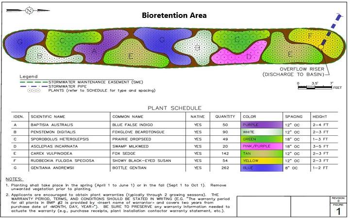

Requirements for a SCM vegetation plan are as follows.
Northeast Tennessee Water Quality
The plan must be prepared by a professional qualified in landscape design by their education or experience.
The plan shall include one or more labeled plans/details (to scale) showing the plants to be installed, their numbers, and locations. Plan notes showing a plant schedule and installation instructions are encouraged. This additional information allows both the plant installer at the time of construction, as well as the person(s) responsible for maintenance of the SCM after construction, to understand the original vegetation design and its compliance with the minimum standards.
Landscaped SCMs may not be recognized under the local government’s codes as property landscaping. Therefore, additional requirements for property landscaping may apply.
5.1.8 Protection Design Guidance
SCMs designed for stormwater quality purposes must be maintained in keeping with the approved SCM design for the life of the land development 1 . Design professionals can assist property owners with this requirement by including protective features in and around SCMs to limit the potential for damage by external factors. Often, the landscape and impervious features around an SCM can be tailored to its specific needs, and therefore used to protect its critical components.
For bioretention areas, protection is especially important for the planting bed. Encroachments by vehicles, heavy equipment, and pedestrians can damage plants, compact the engineered soil mix, damage the overflow structure, and potentially deform or crush the underdrain. However, bioretention areas are especially well-suited to a variety of protection methods that can enhance the property’s landscape aesthetic or impervious surface function. Protection methods that work well are listed in Table 5.1.8.1. Examples of bioretention protection are shown in Figure 5.1.8.1.
Passive Protection Measures
Natural fencing around the perimeter (e.g., dense, woody, or prickly shrubs or tall grass)
Driveways, sidewalks, or walkways around the SCM
Pedestrian benches on the perimeter
Geometry/sizing to allow maintenance without vehicles/equipment entering the bioretention area
Active Protection Measures
Decorative fencing
Curbs or curb blocks
Hardscaping (cobble, boulder, or block edging; block walls; etc.)
Educational or directive (e.g., no pets) signs
Pet waste stations and trash cans near the SCM
* The list presented in the table is not exhaustive. There may be other possible protection measures.
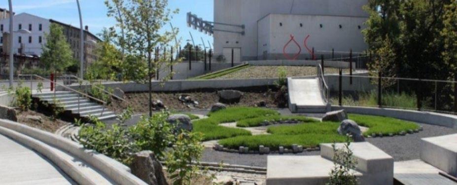
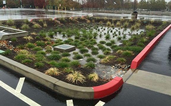
1 Tennessee Department of Environment and Conservation Rule 0400-40-10-.04
Table 5.1.8.1 Bioretention Protection Methods*
Figure 5.1.8.1 Examples of Bioretention Area Protection
Left: Pathways along and through a bioretention area guide pedestrians to appropriate places to walk (City of Philadelphia, PA Water Department); Right: Concrete curbing around a parking lot bioretention area keeps vehicles and people out while allowing stormwater in (Sacramento State University);
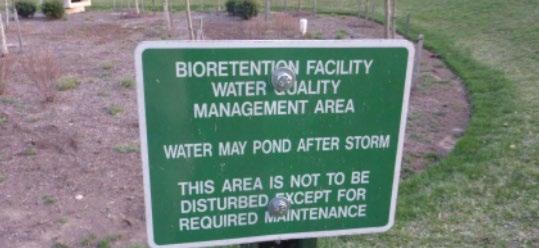
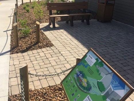
5.1.9 Site Preparation and Land Disturbance Requirements
The following information is provided to support proper and effective construction and protection of bioretention areas during land disturbance activities and site construction. Mandatory requirements are identified using “shall” or “must.” All other statements can be regarded as non-mandatory guidance. Site preparation and land disturbance practices described in this section shall be shown on Erosion Prevention and Sediment Control (EPSC) plan for the proposed land development. Table 5.1.9.1 provides requirements for site preparation and land disturbance practices for land developments with bioretention areas.
Table 5.1.9.1
Site Preparation and Land Disturbance Requirements for Bioretention Areas
SCM Type Policy
Preservation of the native, uncompacted soil during site construction and construction phasing and sequencing are critical to the success of a Group 1 bioretention area. Thus, the following requirements apply:
The location of the bioretention area shall include a protection zone extending a minimum of 10 feet around the perimeter of the bioretention area and shall be protected from encroachments by vehicles, equipment, and workers during site construction. To the extent practical, work within the perimeter should be confined only to that required for installation of the bioretention area.
Bioretention Areas Without an Underdrain (Group 1 only)
The bioretention area protection zone shall be identified and marked prior to commencement of land disturbance activities using highly visible orange fencing (or similar visible protective measures) and signage to advise construction personnel not to enter the area. Construction vehicle and equipment parking, thoroughfares, wash-off areas, and sediment traps/basins shall not be located in the bioretention area protection zone.
Clearing, grubbing, and grading using heavy equipment is prohibited in the protection zone. When these activities are necessary for construction of the bioretention area, hand tools or smaller equipment that can reach into the protection zone must be used to avoid compaction of the native soil within the zone.
Erosion prevention and sediment control (EPSC) measures must safeguard the protection zone both prior to, during, and if necessary, after its installation
Site construction shall be sequenced such that the bioretention area is installed only after the area draining to it has been fully and permanently stabilized.
Figure
Left: A sign indicating how the bioretention area functions and protecting against foot or equipment traffic (source unknown). Right: Decorative fencing, benches, and signage all help protect this bioretention area (City of Oak Ridge, TN)
Northeast Tennessee Water Quality
Bioretention Areas with an Underdrain (Group 2 only)
Construction phasing and sequencing are critical to the success of Group 2 bioretention areas
Thus, the following requirements apply:
Bioretention areas can infiltrate stormwater even though they have an underdrain. This capability should be preserved during construction, if possible, by identifying and protecting the bioretention area location using highly visible orange fencing (or similar visible protective measures) and signage to advise construction personnel not to enter the area.
Construction vehicle and equipment parking, thoroughfares, roadways, parking, and washoff areas shall not be located where bioretention areas will be located.
When protection from clearing and grading activities is not possible, the bioretention area shall not be excavated lower than 2 feet above the final design elevation of the bottom of the practice. This prevents further compaction of the soil below the practice by vehicles and heavy equipment. Once the area is excavated to grade, the impacted area must be tilled to a depth of 12 inches below the bottom of the bioretention area.
Bioretention areas that have a drainage area less than 2 acres may be used as sediment traps (NOT SEDIMENT BASINS) during construction. When the bioretention area is to be used as a sediment trap, the following requirements shall apply:
(1) The maximum excavation depth of the trap must be at least 1 foot higher than the post-construction (final) invert (bottom of the bioretention area).
(2) Conversion of the temporary sediment trap to a permanent bioretention area shall include trap dewatering, sediment removal, and permanent stabilization.
The bioretention area shall be protected using erosion prevention and sediment control measures before, during, and, if necessary, after installation.
Site construction shall be sequenced such that the bioretention area is installed only after the area draining to it has been fully and permanently stabilized.
Figures 5.1.9.1 and 5.1.9.2 provide examples of good site preparation and land disturbance practices, and results of poor practices, respectively.
Figure 5.1.9.1 Examples of Good Site Preparation and Land Disturbance Practices


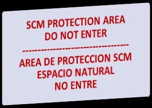
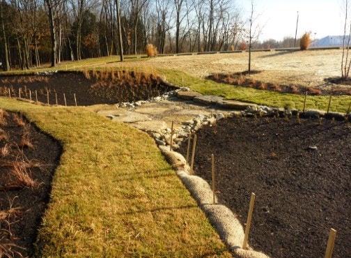
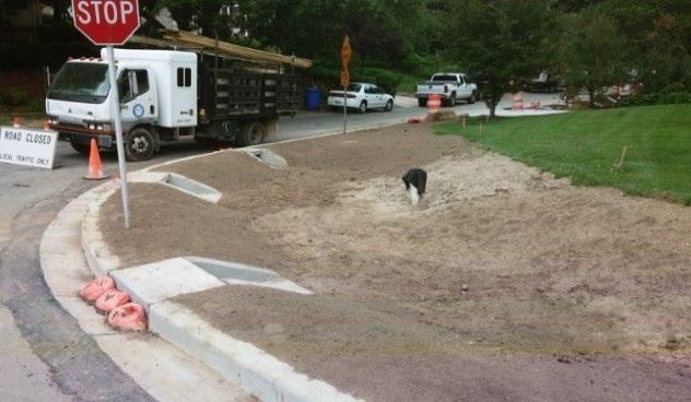
Left: A future bioretention area is protected during construction (adapted from a photo by North Carolina State University Extension); Middle: erosion prevention and sediment control measures surround this newly installed bioretention area until construction in the area surrounding it is fully completed. (University of Cincinnati’s Clermont College, the Water Environment Foundation); Right: Inlets are blocked to prevent inflows of stormwater during construction of a bioretention area. Note that all surrounding areas are fully stabilized. (Source: Montgomery County, MD Department of Environmental Protection)
Figure 5.1.9.2
Results of Poor Land Disturbance Practices During Bioretention Area Construction
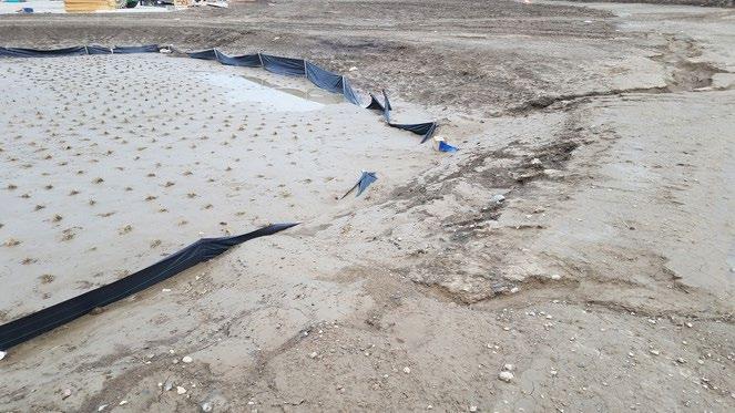
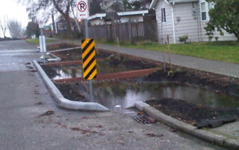
5.1.10 Installation Requirements
The information in Table 5.1 10.1 provides a typical construction sequence to properly install bioretention areas. These steps may be modified to reflect different applications or site conditions. Installation practices shall be shown in the EPSC and WQMP plans, as appropriate for the proposed land development.
Table 5.1.10.1 Installation Steps
Step
Step 1
Step 2
Step 3
Requirement
The installation site shall be checked for existing utilities prior to construction. Construction of the bioretention area shall be performed only after the area draining to it has been fully stabilized to prevent sediment discharges. Where this requirement cannot be met, a temporary bypass shall be designed to prevent stormwater discharge to the bioretention area until its drainage area is fully stable. It may be necessary to block certain curb or other inlets while it is being constructed. Supervision during construction is required to ensure the bioretention area is constructed/installed in accordance with the approved EPSC and WQMP plans. The design professional or a designee under their supervision must inspect the bioretention area at critical stages of construction. Examples of critical stages of construction include protection zone and erosion prevention and sediment control measure installation, excavation, underdrain installation, and final inspection. This ensures that the contractor’s interpretation of the plan is consistent with the design professional’s intentions and allows the design professional to certify (in the as-built plan) that the bioretention area is built in keeping with the permitted plan.
Construction sites can have many different contractors responsible for different portions of the site or aspects of construction. Therefore, subtle differences in site grading, drainage, and paving elevations from those identified in the design, or relative to different areas/aspects of construction, can affect the hydraulics of the proposed bioretention area. The following practices should be done prior to construction to ensure the approved design is still valid:
During the preconstruction meeting, review and confirm that the actual boundaries of the bioretention area’s contributing drainage area and inlet elevations conform with the approved design.
Any changes that result from the preconstruction meeting must be shown as a revision to the WQMP and resubmitted to the local government for approval. This includes changes to material certifications for aggregate, engineered soil mix, and liners if not approved prior to the preconstruction meeting.
Install protection and erosion prevention and sediment control measures as indicated in Table 5.1 9. 1 above.
Left: Improper sequencing and poor erosion prevention and sediment control measures destroyed this bioretention area before it coul d ever start functioning (Source: Cuyahoga Soil & Water Conservation District); Right: Failed bioretention area due to poor land disturbance and construction (Source: City of Ballard, WA)
Northeast
Step
Step 4
Step 5
Step 6
Step 7
Step 8
Step 9
Requirement
Special protection measures, such as erosion control fabrics, may be necessary to protect vulnerable side slopes from erosion during the construction.
Pretreatment measures shall be excavated first and then sealed to trap sediments prior to installation of the main treatment area.
Excavate the bioretention area to its appropriate design depth and dimensions. Excavators or backhoes, if used, must be located on the sides of the bioretention area and have adequate reach inside the footprint for full excavation.
For bioretention areas without an underdrain, DO NOT allow vehicles or heavy equipment in the protection zone.
For bioretention areas with an underdrain, DO NOT allow vehicles in the main treatment area. For excavation of large bioretention areas, use a cell construction approach where the area is split into 500- to 1,000-square foot temporary cells with a 10- to 15-foot earth bridge in between. This allows cell excavation from the sides.
Continue to avoid the use of heavy equipment and vehicles in the main treatment area (and protection zone) for the remainder of the steps listed below.
Scarify (loosen by ripping) the bottom soils to a depth of 6 to 12 inches to promote greater infiltration.
Proceed to steps 7 through 11, taking care to place bioretention area layers in ways that do not cause compaction of the in-situ soil beneath the SCM.
If using a geotextile fabric, place the fabric only on the sides of the bioretention area (with a 6-inch overlap). Place the required depth of stone on the bottom, install the perforated underdrain pipe (if part of the plan) and its required stone jacket, and add the choking layer.
Apply the engineered soil mix in 12 inch lifts until the desired top elevation of the bioretention area is achieved.
Wait a few days to check for settlement and add additional engineered soil mix as needed to achieve the design elevation.
Note: The batch receipt confirming the source of the engineered soil mix must be included with the Record Drawing
Install temporary irrigation measures, if needed, to ensure plants will be watered during the remainder of site construction.
Step 10 Install plants as shown in the vegetation plan (see Section 5 1.7 and Table 5.1.7.1 above)
Step 11
Step 12
Place the surface cover (i.e., mulch, river stone, or turf).
If coir or jute matting will be used in lieu of mulch, the matting will need to be installed prior to planting (Step 10), and holes or slits will have to be cut in the matting to install the plants.
Erosion/sediment control devices can be removed from the inlets once the bioretention area’s side slopes have good vegetative stability and the drainage area is fully and permanently stabilized.
If the area draining to the bioretention cell includes newly installed asphalt, the erosion/sediment control devices at inlets should remain in place for at least three storm events after asphalt installation. A substantial amount of fine particles and grit are discharged from newly installed asphalt during the first several storms that produce runoff after installation.
Maintenance will be required to remove the particles and grit if erosion/sediment control devices are removed too early.
Northeast Tennessee Water Quality
Step Requirement
Maintain the bioretention area in keeping with Section 5.1.11 below.
Step 13
Prepare the Record Drawing and submit to the local government for review and approval with the engineer’s as-built certification before a temporary or final Certificate of Occupancy can be obtained. Advise the landowner (i.e., the person(s) taking ownership of the property immediately after its development) of the presence of the bioretention area and provide them with a copy of the property’s Record Drawing and SCM location map. The plan must clearly show the location of the bioretention area on the property and list the activities (and their frequencies) necessary for its proper maintenance.
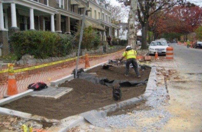
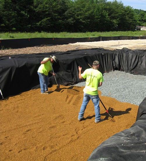
5.1.11 SCM Maintenance on an Active Construction Site

Using hand tools instead of heavy equipment for small bioretention areas can ensure their successful operation after construction. (Far left source: Chesapeake Stormwater Network; Near left source: Courtesy of Stormwater Facilities, www.stormwaterfacilities.com)
SCM maintenance is regulated by local government ordinance from the moment they are installed. As well, SCMs must pass a final inspection prior to construction termination. This inspection will be performed to ensure they are constructed in accordance with the approved WQMP, undamaged, and free of sediment and debris. Thus, SCM maintenance is good practice to ensure construction termination goes smoothly. Relevant policies are as follows:
The property owner is responsible for SCM maintenance. If the property is still an active construction site, these responsibilities may fall to the land disturbance permittee until the project receives final approval from the local government and/or a Certificate of Occupancy.
Property owners may have others, such as a site contractor or landscaping company, maintain the bioretention area on their behalf. However, the local government will hold the property owner responsible for ensuring it is maintained in proper operating condition (i.e., as designed and constructed) regardless of who performs maintenance activities.
Maintenance activities, which include ensuring proper operation of the SCM as designed and required SCM inspections, must begin immediately following installation of the bioretention area.
Maintenance activities shall be performed in keeping with the Northeast Tennessee SCM Inspection and Maintenance Manual Additional guidance on maintenance of newly installed bioretention areas located on active construction sites is provided in Table 5.1.11.1
Table 5.1.11.1 Maintenance Activities for Newly Installed
Contributing Drainage Area
Keep the contributing drainage area clean. Sweep trash, debris, and sediment frequently so that it does not wash in the basin during a rain event.
The contributing drainage area should be fully stabilized before installation of the bioretention. If it is not, prevent inflows to the area by blocking or using diversion measures until the contributing drainage area is fully and permanently stabilized.
Cover stockpiles of construction and landscape materials to prevent their exposure to rainfall.
Figure 5.1.10.1 Examples of Good Installation Practices for Bioretention
Bioretention Areas
Northeast Tennessee Water Quality SCM
Area or Component
Bioretention Area
Education
Post-Installation Maintenance Requirement
When asphalt is placed in the contributing drainage area to a bioretention area, keep erosion/sediment control devices at inlets for at least three storm events after asphalt installation. This prevents the discharge of fine particles and grit from the newly installed asphalt to the bioretention area.
Ensure bioretention area plants are watered and growing as expected.
Remove and replace diseased, dying, or dead plants as soon as they are noticed.
Ensure the planting bed remains free of sediment and wastes.
Ensure vehicles, equipment, and people are not allowed in the bioretention area. Evidence of unwanted entry may look like tire tracks or footprints; mulch or stone displacement, or damage to components or vegetation; immediately determine and eliminate the cause and repair the area.
Consider installing temporary fencing.
Visually observe bioretention area function after rain events; there should be no standing water within 48 to 72 hours after a storm event, depending on the frequency of rainfall. If long-standing water is observed:
Inspect underdrain via the observation well looking for standing water indicative of a blockage or damage; make repairs if needed.
If underdrain/outlet blockages and damage can be ruled out, then the engineered soil mix may be clogged. This repair requires removal and replacement of the engineered soil mix, underdrain cleaning, and plant removal and reinstallation.
Inspect the bioretention area for erosion or significant sediment buildup; immediately determine and eliminate the cause and repair the area.
Alert onsite subcontractors to the SCM and the following requirements:
No muddy vehicles or equipment in the drainage area to the basin.
No stockpiling of material in the bioretention area.
No uncovered stockpiles in the contributing drainage area
Block inlets prior to asphalt placement in the contributing drainage area.
Remove sediment, trash, debris, and empty trash cans frequently.
Advise landscaping subcontractors on proper protection and maintenance of the bioretention area, especially the following:
No heavy equipment (hand tools only).
No dumping of lawn clippings or landscape debris
Plant maintenance needs/requirements (see above).
Mulch specifications (i.e., clean, undyed, natural hardwood mulch)
5.1.12 References
ARC. Georgia Stormwater Management Manual Volume 2 Technical Handbook, 2016 Edition. Atlanta Regional Commission, 2016
5.2 Cistern/Rainwater Harvesting
design specification SCM Group: 1
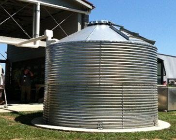
Overview
Cisterns are low impact development stormwater control measures (SCMs) used to intercept, divert, store, and release rain falling on rooftops for future use. This reduces the volume of stormwater discharged from a development. Less volume discharged means less pollutants are discharged. So, cisterns remove pollutants by removing stormwater. Cisterns are becoming more popular because of their versatility in uses, location, configuration, and size. (Photo at right courtesy of Chattanooga Area Food Bank)
ADVANTAGES/BENEFITS
Reduces stormwater volume and thus pollutant discharges
Provides a water source for non-potable uses (toilet flushing, irrigation)
DISADVANTAGES/LIMITATIONS
The intended use must support the drainage of the harvested WQv to drain completely from the cistern within 72 hours of capture
Requires competent person for cistern operation, maintenance, and repair
Plumbing codes must be followed for cisterns that provide water to the interior of buildings
Not suitable for potable water use with tar, gravel, and/or asbestos shingled roofs
LOCATION, SIZING, & COMPONENTS
Sized based on the size of the contributing drainage area, local rainfall patterns, and projected demand for harvested rainwater
Pretreatment should be provided upstream of all cisterns to prevent leaves and other debris from clogging the system
Above ground cisterns must be UV-resistant and opaque to inhibit algae growth
Underground cisterns must be designed to support anticipated loads
LONG-TERM
PROTECTION
The cistern must remain operational throughout the year and thus be protected from freeze/thaw conditions
Protect from tampering
Suitable for a wide variety of protective designs
LONG-TERM MAINTENANCE
Primary routine maintenance activities will be pretreatment device, cleaning, routine draining of the cistern, ensuring any pumps are operational, inspecting for erosion around overflow, and ensuring algae is not growing in the tank
Consider permanent signs to dissuade tampering
5.2.1 General Description
Cisterns, also known as rainwater harvesting systems, are a stormwater management practice of intercepting, diverting, and storing rainfall for later use. In a typical cistern, rainfall is collected from a gutter and downspout system, screened, “washed,” and conveyed into an above- or below-ground tank. Once captured, stored water may be used for non-potable indoor and outdoor uses. This reduction in stormwater discharges means there is a similar reduction in the pollutant load discharged from a property than would be discharged if a cistern were not present. Thus, if properly designed, operated, and maintained, cisterns can significantly reduce post-construction runoff rates, volumes, and pollutant loads on development sites. Figure 5.2.1.1 shows examples of surface and subsurface applications.
Figure 5.2.1.1 Examples of Surface and Subsurface Cisterns
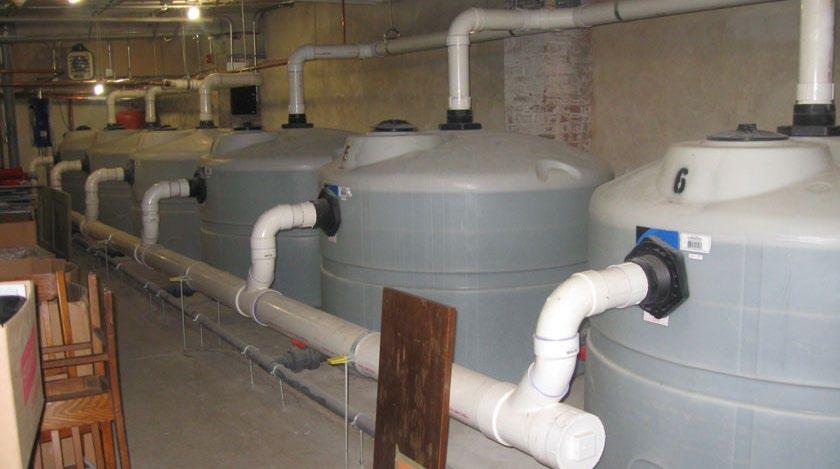
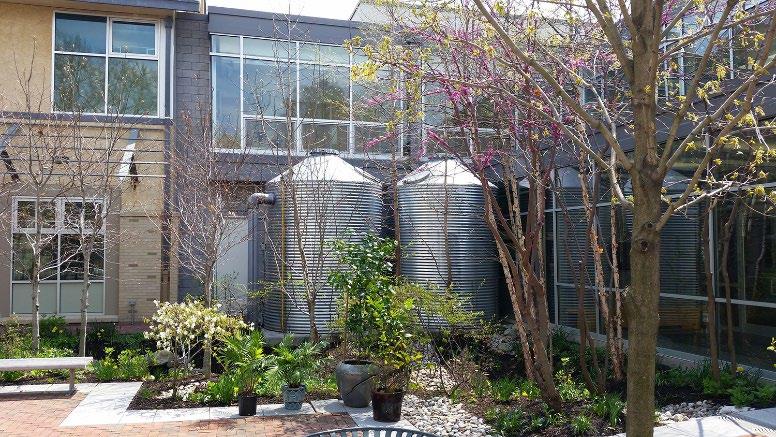
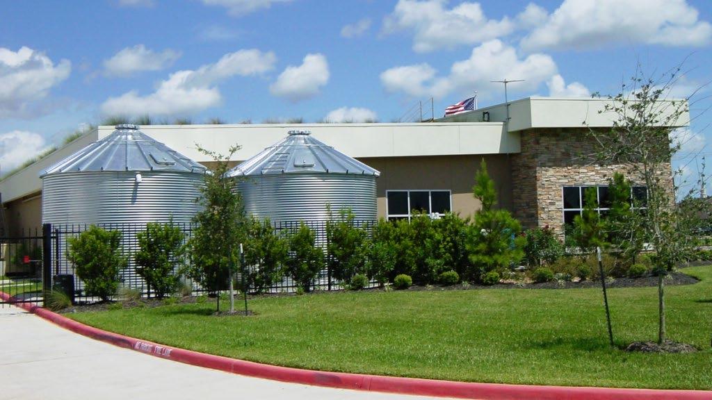
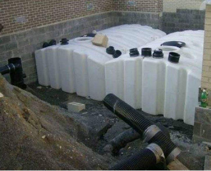
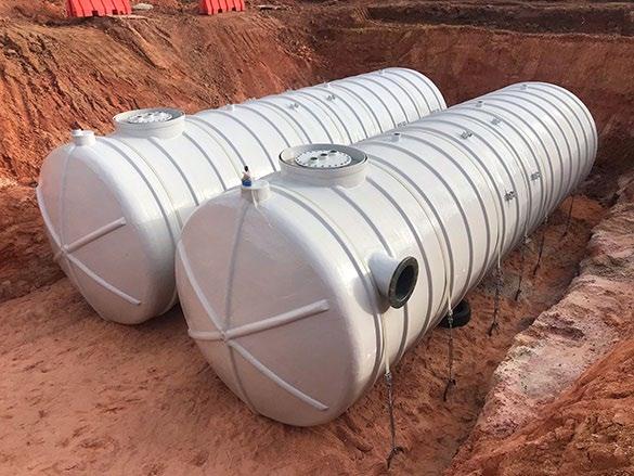
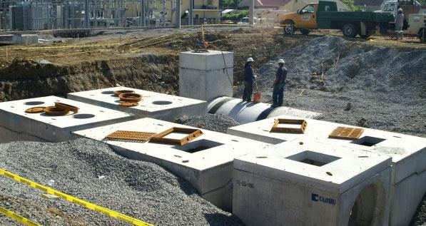
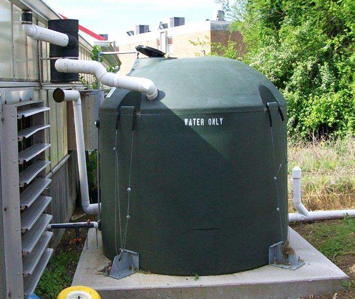
Top left: Surface cisterns in Philadelphia, PA, Philadelphia Water Department; Top right: Subsurface cistern system in Philadelphia, PA, Philadelphia Water Department; Middle left: Galvanized steel (Source: Protank); Middle right: Multiple precast concrete units (Source: unknown); Bottom left: Polyethylene Modular Units (Source: VADCR, 2011); Bottom middle: Fiberglass units (Source: Rain Harvest Systems);Bottom right: Polyethylene tank (Source: Knox County, TN)
Northeast
When compared to other SCMs, cisterns have relatively few physical constraints that impede their use on a development and can be applied on a wide variety of development sites. They are especially well-suited for use on commercial, institutional, municipal, and multi-family residential buildings on urban and suburban development. Beyond physical constraints, cisterns have a moderate to high construction cost, and a relatively high maintenance burden, but require a relatively small amount of surface area when compared with other SCMs. Cisterns are often a component of “green buildings,” such as those that achieve certification in the Leadership in Energy and Environmental Design (LEED) Green Building Rating System.
Cisterns are sometimes referred to as a rain tank or a rain barrel. For purposes of this document, these terms are used for small cisterns that are employed in single family residential applications, most often for purposes of providing water for a home’s landscape or garden. However, homeowner operation and maintenance of home rain barrels typically does not meet the performance standards required for an SCM (i.e., water re-use may be performed on a hap-hazard, as-needed basis). Further, local government administration and oversight of these standards would be difficult and costly at the single-family residential lot level. While the local government does not discourage homeowners from employing rain barrels at their homes, they cannot be proposed by a design professional to meet local government stormwater quality standards for a development. This rule does not exclude the installation of a cistern in a residential common area that has a regular need/use for harvested water and will have frequent onsite property/facilities management to oversee SCM operation, maintenance, and repairs.
5.2.2 Cistern Qualification as an SCM
A cistern can only be identified as a water quality SCM if it is designed to achieve two important objectives on a consistent, year-round basis: 1) rainwater harvest; and 2) rainwater re-use. These two objectives are not mutually exclusive as both must be achieved for the cistern to provide long-term value in pollutant reduction. Without harvest, rainwater cannot be re-used for other purposes. Without re-use, the cistern will not have storage capacity to harvest more rainwater and thus will not reduce pollutants throughout the year.
This specification focuses on providing a design framework for addressing harvest and reuse of the WQv. Thus, local government approval of a cistern as the selected SCM to meet stormwater quality control requirements is contingent upon the following two requirements.
1. The cistern must have a consistent, year-round, onsite drawdown/demand for the harvested water. The demand for harvested water must be able to withstand periods of drought and inundation. While seasonal practices (such as irrigation) may be incorporated into the site design, they must accept cistern drawdown at least an equal rate during non-seasonal periods or a secondary use must be readily available (e.g., discharge to an alternate use or secondary SCM for treatment during non-irrigation months).
2. The development for which the cistern is proposed must have a competent operator for oversight, maintenance, and repair of the cistern (e.g., the owner, a dedicated property or facilities manager, etc.). Automated cisterns are preferred; however, if the cistern will be operated manually, the operator must be located onsite.
Therefore, the cistern design configurations presented in this specification are targeted for continuous (year-round) use of rainwater through indoor use, irrigation, and/or treatment in a secondary SCM.
5.2.3
Typical Design Configurations
The three basic types of cistern system configurations that can meet user demands and local government stormwater objectives are described below.
CONFIGURATION 1: Year-round indoor use with optional seasonal outdoor use. The first configuration is for yearround indoor use along with optional seasonal outdoor use, such as irrigation. Because there is no onsite secondary SCM incorporated into the design for non-seasonal (or non-irrigation) months, the system is designed for the interior
use, which must have a water demand sufficient to provide for WQv drawdown within 72 hours as required. Seasonal outdoor use is then an added benefit. It should be noted that the seasonal irrigation will provide an economic benefit in terms of water usage. In this configuration, the cistern tank is sized, at a minimum, for the 1-inch WQv rainfall, plus any additional water needs for indoor use or optional outdoor use
CONFIGURATION 2: Seasonal outdoor use and approved year-round secondary SCM The second configuration uses stored rainwater to meet a seasonal or intermittent water use, such as irrigation. However, because these uses are only intermittent or seasonal, this configuration also relies on an approved secondary SCM to treat stormwater during the off-season period. The cistern’s drawdown and release rate shall be designed based on the water quality treatment mechanisms employed by the receiving secondary SCM.
The secondary SCM serves as the “backup” SCM during non-irrigation months. This configuration is not considered a treatment train since the cistern serves only as a water storage and delivery device to the secondary SCM. Therefore, a volume reduction cannot be taken for the downstream (secondary) SCM. In fact, both the cistern and the secondary SCM may need to be “upsized” in this configuration. If the cistern will discharge to a Group 2, 3, or 4 SCM, the cistern tank must be sized, at a minimum, for the WQv rainfall requirement of the secondary SCM. For example, if the cistern will discharge to an urban bioretention area, the cistern tank must be sized to capture the 1.25-inch rainfall (per the WQv calculation methods described in Chapter 3), and the urban bioretention area sizing must include the contributing drainage area for the cistern. Group 1 SCMs, having a WQv rainfall requirement of 1-inch, can be most easily employed as a secondary practice to the cistern since it, too, is considered a Group 1 SCM.
CONFIGURATION 3: Year-round indoor use, optional seasonal outdoor irrigation, and treatment in a secondary SCM, if necessary. This configuration provides for a year-round internal non-potable water demand and seasonal outdoor, automated irrigation system demand It incorporates a secondary SCM to provide water treatment when indoor demand and/or seasonal irrigation cannot provide for WQv drawdown within 72 hours on a year-round basis. In this case, cistern sizing and drawdown is addressed in the same manner as Configuration 2 above.
5.2.4 System Components
Whether it is used to supply water for non-potable indoor or outdoor uses, a well-designed cistern system typically consists of the major components listed below. These components are shown in Figures 5.2.4.1 and 5.2.4.2. Some cistern systems may require additional components, depending on application, design configuration, and other site-specific factors, like:
the roof surface,
the rainwater collection and conveyance system (e.g., gutter and downspout system),
pretreatment devices (e.g., leaf screens, first flush diverters, roof washers),
the storage tank,
the distribution system (which may or may not require a pump, depending on site characteristics, and
the overflow pipe (which allows excess stormwater to bypass the cistern).
When designing a cistern system, design professionals should consider each of these components, as well as the size of the contributing drainage area, local rainfall patterns, and projected water demand, to determine how large the storage tank must be to provide enough water for the desired non-potable indoor or outdoor use. Commercial cistern manufacturers can provide substantial information to assist design professionals in the selection of the appropriate cistern for the intended application and site characteristics.
5.2.4.1 Basic Components of an Above Ground Cistern (Source: Georgia Department of Community Affairs, 2009)
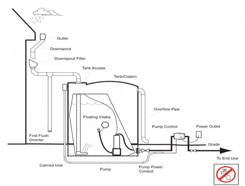
5.2.4.2 Basic Components of an Underground Cistern (Source: Georgia Department of Community Affairs, 2009)
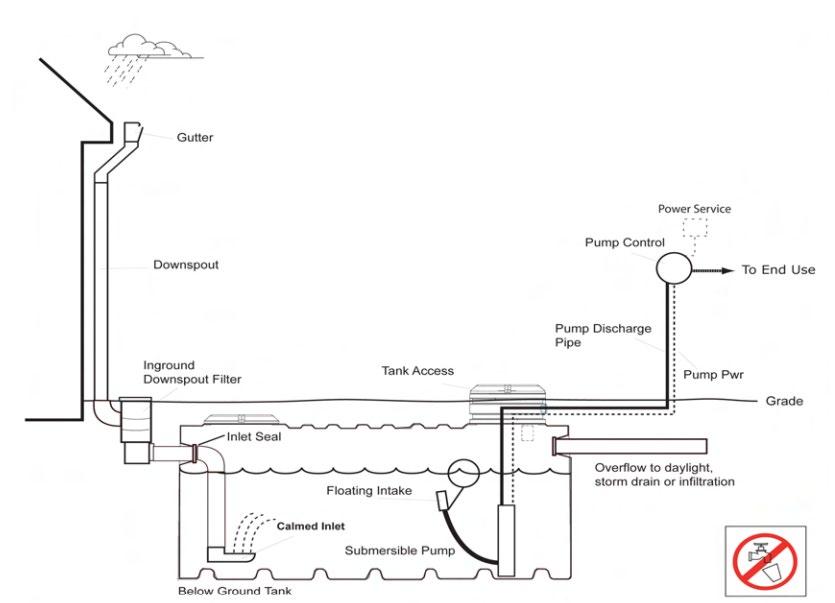
Figure
Figure
5.2.5 Limitations of This Design Specification
The criteria provided in the remainder of this design specification do not describe the complete design of a working cistern. Rather, they are intended as “guardrails” for cisterns that are proposed as SCMs, so they can meet local government stormwater quality control requirements and adhere to plumbing/building codes if they are intended for indoor water supply uses. Within the boundaries provided by these criteria, design professionals are strongly encouraged to work with a commercial cistern manufacturer to ensure proper design of functional cisterns.
5.2.6 SCM Suitability
Use Table 5.2.6.1 to determine if a cistern is suitable for the application being considered.
Table 5.2.6.1 Cistern Suitability Factors
Factor
Suitability
Stormwater Quality Treatment Cisterns designed in keeping with the specifications established herein will satisfy local government stormwater quality treatment standards.
Channel Protection
Cisterns are not intended to provide extended detention; therefore, a cistern cannot be used to meet channel protection requirements. However, cisterns can be designed to accept large volumes of stormwater, beyond the WQv. Large volume cisterns can reduce the channel protection volume need by reducing the amount of stormwater discharged to the onsite system.
Detention
Pollutant Treatment Capability
Cisterns are not typically intended to provide detention storage; therefore, a cistern cannot be used to meet detention requirements. However, cisterns can be designed to accept large volumes of stormwater, beyond the WQv. Large volume cisterns can reduce a property’s detention need by reducing the amount of stormwater discharged to the onsite system.
Cisterns can be used to address following common stormwater pollutants however pollutant removal percentages varies and is dependant on the type of cistern used 1 Consult the National Pollutant Removal Performance Database (Version 3) available at www.cwp.org, the National Stormwater Best Management Practices (BMP) Database at www.bmpdatabase.org/ for more information regarding cistern/rainwater harvesting pollutant removal capabilities.
Total Suspended Solids (TSS)
Total Phosphorus (TP)
Total Nitrogen (TN) Fecal Bacteria Metals* varies varies varies varies varies
1 Georgia Stormwater Management Manual, Volume 2 Technical Handbook, 2016 Edition.
*Cadmium, copper, lead, and zinc
Cisterns shall not be used to treat wastes and other pollutants, many types of which are listed below, should they be present in the contributing drainage area to the cistern:
Construction sediment/waste
Treatment of Waste and Other Pollutants
Landscape storage or waste
Sewage, pet, & livestock waste
Medical waste
Household & commercial wastes
Hazardous wastes
Gasoline, motor oils, greases, & other petroleum-based products
Fats, oils, & grease (from food preparation)
Pesticides, fertilizers, herbicides
Other byproducts and waste materials expected, based on the property’s land use
Suitability by Land Use
Privately owned cisterns are not allowed in the public right-of-way.
General suitability criteria by land-use type are as follows. See Chapter 3 (Standards, Methods, and SCM Selection) for more information.
Yes
*These policies do not preclude the use of cisterns on individually owned single family or multi-family residential lots. However, cisterns placed on residential lots will not be considered by the local government as suitable for compliance with local government stormwater management requirements due to the inherent difficulties in oversight and enforcement of long-term protection and maintenance requirements on residential lots.
5.2.7 SCM Location Requirements
Location constraints for cisterns are provided in Table 5.2.7.1
Table 5.2.7.1 Cistern Location Requirements
Physical Element
Minimum SCM Setbacks
Requirement
Minimum setbacks, measured from the cistern, are as follows:
Building foundations:
Overflow devices shall be designed to avoid ponding or soil saturation within 10 feet of building foundations.
Underground tanks should be at least 10 feet from building foundations
Appropriate minimum setbacks from septic drain fields shall be observed.
Secondary SCMs may have setback requirements. Refer to the design specification of the secondary SCM for more information.
Utility Avoidance
Available Space
Cisterns shall not be located above underground dry utility lines (electric, cable, and telephone) and water/wastewater infrastructure. The underground utilities shall be marked and avoided during the installation of underground tanks and piping associated with the cistern system. Design professionals must consult the local utility to determine the horizontal and vertical clearance required between SCMs and dry and wet utility lines.
Adequate space is needed for the cistern’s tank, piping, pumps (if any), overflow, and any secondary SCM. Space limitations are rarely a concern with cisterns if they are included during the initial building design and site layout of a residential or commercial development. Storage tanks can be placed underground, indoors, on rooftops, or within buildings that are structurally designed to support the added weight, and adjacent to buildings.
5.2.8 Design Requirements
Tables 5.2.8.1 and 5.2.8.2 provide local government criteria and guidance for cistern design. Work with a commercial cistern manufacturer for more comprehensive design information.
Table 5.2.8.1 Design Specifications for the Contributing Drainage Area
Design Element
Size No restrictions.
Slope
Specification(s)
No restrictions, however the designer may want to consider the following:
Placing a cistern at a higher elevation may reduce or eliminate water pumping needs.
Cisterns can be useful in areas of steep terrain where other SCMs are inappropriate, provided the systems are designed in a way that protects slope stability.
Restricted to impervious surfaces only, rooftops only preferred.
Typically, rooftops comprise the entirety of a cistern’s contributing drainage area. However, there may be applications where other impervious surfaces could drain to a cistern, especially for cistern tanks located underground.
Design professionals should consider both the intended use for the harvested rainwater and the pollutants expected from the contributing drainage area.
Surface Type and Rainwater Quality
Controls for Waste & Other Pollutants
If the cistern is intended to provide water for uses with significant human exposure (e.g. pool filling, watering vegetable gardens), care shall be taken in the choice of roof materials.
Water harvested from certain types of rooftops, such as asphalt sealcoats, tar and gravel, painted roofs, galvanized metal roofs, sheet metal, or any material that may contain asbestos may leach trace metals and other toxic compounds, making the water unsafe for humans. In general, harvesting rainwater from such roofs should be avoided, unless new information determines that these materials are sufficient for the intended use.
If a sealant or paint roof surface is desired, it is recommended to use one that has been certified for such purposes by the National Sanitation Foundation (ANSI/NSF standard).
Appropriate controls shall be included in the design of the contributing drainage area to the SCM to address any wastes and other pollutants (see Table 5.2.6.1 above) that are expected in the contributing drainage area
Table 5.2.8.2 Design Specification for the Cistern
Design Element
Water Quality Volume (WQv)
Cistern Siting and Access
Soils
Specification(s)
The water quality rainfall depth (P) for determination of WQv: P = 1.0 inch.
Acceptable methods to determine WQv are presented in Chapter 3 (Standards, Methods, and SCM Selection)
Above ground cisterns shall not be located where any part of the system will encounter continuous or dry weather inflows from springs, seeps, sump pumps, wash stations, or other sources.
Cistern placement shall take into consideration accessibility by truck for installation, removal, maintenance, and repair.
Cistern components shall be safely accessible for visual inspection and maintenance. Adhere to local government building codes and OSHA requirements for tank maintenance access via tank openings, stairs, and ladders.
Storage tanks shall only be placed on native soils or on fill in accordance with the manufacturer's guidelines, or in consultation with a geotechnical engineer.
The bearing capacity of the soil upon which the cistern will be placed must be considered, as full cisterns can be very heavy. This is particularly important for above-ground cisterns, as significant settling could cause the cistern to lean or in some cases to potentially topple. An aggregate or concrete base may be appropriate depending on the soils.
Pretreatment
Sizing
Pretreatment of rainwater will likely be needed to remove debris, dust, leaves, and other materials that accumulate on rooftops.
Pretreatment devices typically used for cisterns include leaf screens, roof washers, and first flush diverters.
As with all SCMs, pretreatment devices prevent SCM clogging by screening, filtering, or diverting material that would otherwise build-up within an SCM causing treatment failure and costly repairs.
Pretreatment devices are intended to be more easily accessible and cleaned than the main treatment/storage area of an SCM. Thus, design professionals should take steps to ensure pretreatment devices are designed to be readily accessible for cleaning by cistern operators.
Cisterns intended to meet local government stormwater quality rules alone shall be sized to at least capture the WQv (see the first row in this table).
The required size of a cistern is governed by several factors, including the size of the contributing drainage area, local rainfall patterns, and projected demand for harvested rainwater.
If a rainwater harvesting model is being used to design a rainwater harvesting system, ensure that the precipitation data is provided by NOAA Atlas 14, most recent version.
Materials used to construct storage tanks shall be structurally sound, watertight, and sealed using a water-safe, non-toxic substance.
Repurposed tanks shall only be used if their previous use was storage of potable water or foodgrade products.
Above ground cistern tanks:
shall be UV and impact resistant and shall be opaque to prevent the growth of algae screened to discourage mosquito breeding and reproduction.
shall not have unsecured openings large enough for small children to enter the tank
must be placed on a secure base to prevent cistern from toppling.
Cistern Tanks
Drawdown Time
Piping Systems
Overflow
Underground storage tanks:
shall be designed to support the overlying sediment and any other anticipated loads (e.g., vehicles, pedestrian traffic, etc.).
shall have a minimum of 18 to 24 inches of soil cover and be located below the frost line.
should be buried above the seasonally high-water table (preferred). Buoyant forces can cause a tank to float out of the ground. Ensure underground tanks are sited and protected properly to avoid negative impacts of soils and high-water table.
Shall have a standard size manhole or equivalent opening to allow access for cleaning, inspection, and maintenance purposes. The access point shall be secured/locked to prevent unwanted access.
The WQv shall discharge from the cistern tank within 72 hours following the end of the preceding rain event.
Piping systems for cisterns that will serve indoor water use shall adhere to local government plumbing code, including those regarding water filtering and treatment.
Any hookup to a municipal backup water supply shall be designed in accordance with all applicable codes and shall have a backflow prevention device to keep municipal water separate from stored rainwater.
An overflow pipe or structure shall be provided to allow harvested rainwater to bypass the cistern (or cistern tank) when it reaches its storage capacity. The overflow device must have a conveyance capacity that is equal to or greater than that of the inflow pipe and should direct excess water to secondary storage for later use, or to the onsite stormwater conveyance system. The overflow
device shall not direct discharges over steep slopes or toward other tanks, buildings, and foundations.
Protective measures may be needed to ensure overflow discharges do not cause erosion in pervious areas.
5.2.9 Protection Design Guidance
SCMs designed for stormwater quality purposes must be maintained in keeping with the approved SCM design for the life of the land development 1 Design professionals can assist property owners with this requirement by including protective features in and around SCMs to limit the potential for damage by external factors
For cisterns, damage can be caused by intentional tampering or mishaps caused by vehicles or equipment (e.g., loaders, forklifts, floor cranes, etc.) working in close proximity. Cisterns are especially well-suited to a variety of protection methods. Some of these methods are listed in Table 5.2.9.1 Examples are shown in Figure 5.2.9.1.
Table 5.2.9.1 Cistern Protection Measures*
Tampering
Signage prohibiting tampering without qualified staff
Locating components in locked enclosures
Securing lids, manholes, valves, pumps, etc., with locks
Vehicle/Equipment Damage
Locating components away from high traffic areas
“Shielding” the components with fences, walls, curbs, bollards, or sturdy vegetation (shrubs, etc.)
*The list presented in the table is not exhaustive. There may be other possible protection measures.
5.2.9.1 Examples of Cistern Protection
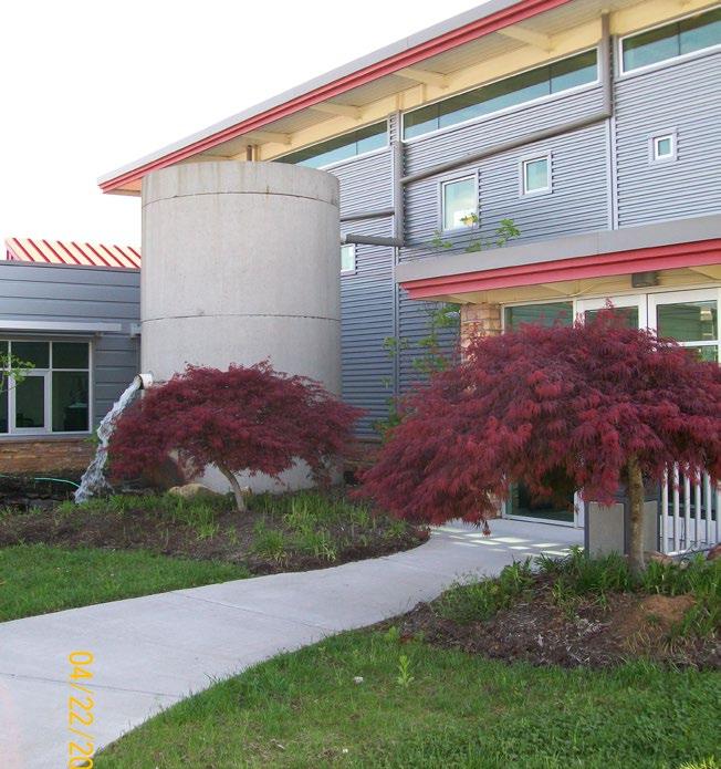
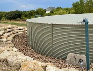
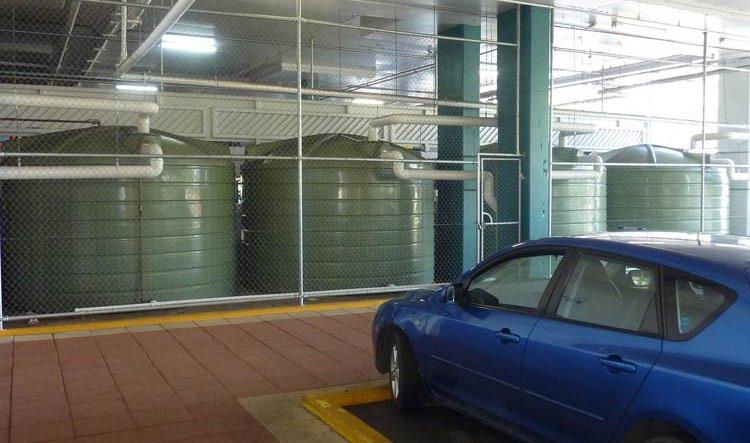
5.2.10 Installation Requirements
Cisterns shall be installed in keeping with the Water Quality Management Plan (WQMP) approved by the local government.
5.2.11 SCM Maintenance on an Active Construction Site
SCM maintenance is regulated by local government ordinances from the moment they are installed. As well, SCMs must pass a final inspection prior to construction termination. This inspection will be performed to ensure they are constructed
5.2 Cistern Design Specification Version: September 1, 2024
Figure
Left: A cistern is located away from high traffic areas and shielded by plants. (Hallsdale Powell Utility District offices, Knoxville, TN); Middle: Hardscaping protects this Pioneer® Metal Water Tank (www.rainranchers.com); Right: Indoor cisterns protected by fencing, high visibility paint, and vehicle curbs (The Tank Factory).
in accordance with the approved WQMP, undamaged, and free of sediment and debris. Thus, SCM maintenance is good practice to ensure construction termination goes smoothly. Relevant policies are as follows:
The property owner is responsible for SCM maintenance. If the property is still an active construction site, these responsibilities may fall to the land disturbance permittee until the project receives final approval from the local government and/or a Certificate of Occupancy.
Property owners may have others, such as a site contractor or landscaping company, maintain the cistern on their behalf. However, the local government will hold the property owner responsible for ensuring it is maintained in proper operating condition (i.e., as designed and constructed) regardless of who performs maintenance activities.
Maintenance activities, which include ensuring proper operation of the SCM as designed and required SCM inspections, must begin immediately following installation of the cistern
Maintenance activities shall be performed in keeping with the Northeast Tennessee SCM Inspection and Maintenance Manual. Additional guidance on maintenance of newly installed cisterns located on active construction sites is provided in Table 5.2.11.1.
Keep the cistern’s contributing drainage area clean Consider:
construction activities that will occur in the contributing drainage area (usually on a rooftop) that may result in waste (roofing materials packaging, nails, grit, etc.).
Contributing Drainage Area
Cistern
construction and landscape activities or materials stockpiles in the areas near the cistern’s contributing drainage area that can be carried onto the roof by wind Cover temporary stockpiles of construction and landscape materials to prevent wind exposure.
seasonal or storm blown landscape litter falling from nearby trees (leaves, branches, etc.)
See also the post-installation maintenance requirements for the secondary SCM, if one is present
Visually observe the cistern’s function when it rains. Check for system leaks, adequate drawdown of the WQv (within 72 hours), and tank stability. Repair problems immediately.
Ensure the secondary SCM (if present) is maintained according to its post-installation maintenance requirements.
If protective measures (fencing, bollards, enclosure) are not yet present, secure the area as appropriate for remaining activities. If needed, mark the area with high-visibility fencing or tape.
Alert onsite subcontractors to the location of the cistern and how to avoid it.
5.2.12 References
ARC. Georgia Stormwater Management Manual Volume 2 Technical Handbook, 2016 Edition. Atlanta Regional Commission, 2016
Georgia Department of Community Affairs, 2009. Georgia Rainwater Harvesting Guidelines, 2009 Georgia Amendments to the International Plumbing Code, Appendix I. Area or Component
Table 5.2.11.1 Maintenance Activities for Newly Installed Cistern
Post-Installation Maintenance Requirement
5.3 Dry Enhanced Swale
design specification
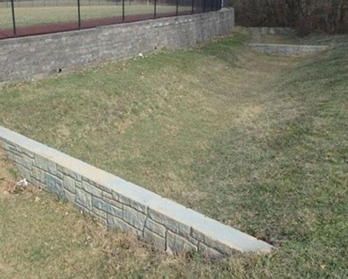
STORMWATER QUALITY CONTROL
Overview
SCM Group(s): 1 & 2
Dry enhanced swales are structural stormwater control measures SCMs that capture and treat the water quality volume (WQv) within dry cells formed by check dams or other means. The primary stormwater treatment mechanism of a dry enhanced swale is biofiltration. Infiltration and evapotranspiration are secondary mechanisms. These SCMs can also be designed as part of the onsite stormwater conveyance system for large storms (up to the 25-year event). (Photo on left from MD Dept. of Environment)
ADVANTAGES/BENEFITS
Provides stormwater treatment and runoff conveyance
Less expensive to install than curb-and-gutter
Reduces runoff velocity
Easy to maintain
DISADVANTAGES/LIMITATIONS
Does not provide stormwater detention
Cannot be used on slopes greater than 4%
Channel Protection Volume (CPv) No
Reduces runoff velocity
SCM operation is allowed only after the SCM’s drainage area is fully and permanently stabilized
DESIGN CONSIDERATIONS FOR LOCATION, SIZING, & COMPONENTS
Maximum contributing drainage area is 5 acres
Channel slope cannot exceed 4%
Typical SCM Footprint Size
(percent of contributing impervious drainage area, if sized for stormwater quality control only)
Permissible bottom width ranges from 2 to 8 feet
Minimum 2-foot separation from seasonally high-water table
Runoff pretreatment is required at all inlets
Energy dissipation is required at all inlets
Minimum required distance from the edge of buildings to the edge of a dry enhanced swale ranges from 10 to 100 feet
DESIGN CONSIDERATIONS FOR LONG-TERM PROTECTION
Primary concerns are plant damage and soil compaction
Suitable for a wide variety of SCM protection designs (curb blocks, plant borders, rocks/cobbles, decorative fencing, signage, etc.)
DESIGN CONSIDERATIONS FOR LONG-TERM MAINTENANCE
Primary routine maintenance activities will be inlet, pretreatment device, and channel cleaning, and grass/plant care
Dense, healthy grass is a must for SCM function
Locate the SCM near a water source to allow grass watering during extremely dry periods
Consider permanent signs to dissuade entry and use of SCM for pet relief or extra parking if SCM is near a pedestrian or parking area
5.3.1
General Description
Dry enhanced swales are SCMs designed for pollutant removal and stormwater conveyance. They differ from a normal drainage channel or swale because they have components that provide stormwater treatment of the Water Quality Volume (WQv). In fact, enhanced swales are shallow, linear bioretention areas covered with grass. They are designed with limited longitudinal slopes to force the WQv to flow slow and shallow, thus allowing particulate filtration and erosion protection. Berms and/or check dams installed perpendicular to the flow path further slow the water and allow the WQv to infiltrate into a bed of engineered soil mix. In most applications in northeast Tennessee, the engineered soil mix will overlay an underdrain The WQv will biofilter through the engineered soil mix before entering the underdrain as cleaner water. Infiltration into the surrounding in-situ soil will occur if an underdrain is not present
Enhanced swales must not be confused with a filter strip or grass channel Filter strips and grass channels do not include an engineered soil mix and underdrain; thus swales provide a much higher level of water quality treatment. However, both a grass channel and filter strip may be used for pretreatment of stormwater before its entry into the enhanced swale.
5.3.2 Design Applications
Dry enhanced swales are typically used in place of stormwater pipes and grass channels to provide treatment of the WQv from one or more upstream impervious areas along with conveyance of stormwater from larger storms (see Figure 5.3.2.1) Uses along parking lot edges, private roadways, and paved trails are common.
Figure 5.3.2.1 Examples of Dry Enhanced Swale Applications
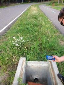
5.3.3 Feasibility
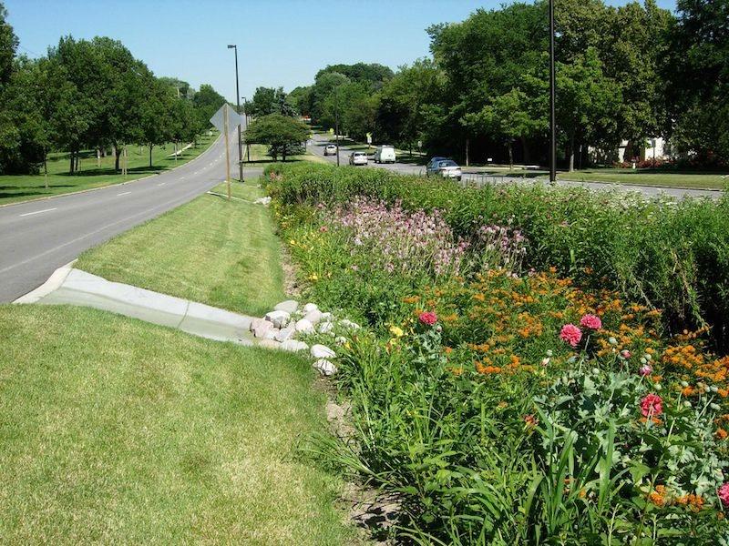
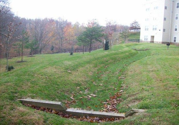
Use Table 5.3.3.1 to determine if a dry enhanced swale is suitable for the application being considered.
Table 5.3.3.1 Dry Enhanced Swale Suitability Factors
Stormwater Quality Treatment Dry enhanced swales designed in keeping with the specifications established herein will satisfy local government stormwater quality treatment standards.
Channel Protection
Typically, dry enhanced swales are not used to provide extended detention of the channel protection volume (CPv). However, for small sites, it may be possible to size a swale to manage the CPv.
Detention Dry enhanced swales do not provide stormwater detention
Left: A dry enhanced swale in Parma, Ohio. Note the underdrain that empties into the outlet structure. (NC State Extension Publications); Middle: Dry enhanced swale in a roadway median (Soils.org); Right: A dry enhanced swale in Montgomery County, MD (North Carolina Dept of Environmental Quality).
Pollutant Treatment
Capability
Treatment of Waste and Other Pollutants
Dry enhanced swales can be used to address following common stormwater pollutants 1:
1 Georgia Stormwater Management Manual, Volume 2 Technical Handbook, 2016 Edition.
*Cadmium, copper, lead, and zinc
Dry enhanced swales shall not be used to treat wastes and other pollutants, many types of which are listed below, should they be present in the contributing drainage area to the swale:
Construction sediment/waste
Landscape storage or waste
Sewage, pet, and livestock waste
Medical waste
Household & commercial wastes
Hazardous wastes
•
Suitability by Land Use
Gasoline, motor oils, greases, and other petroleum-based products
Fats, oils & grease (from food preparation)
Pesticides, fertilizers, herbicides
Other byproducts and waste materials expected, based on the property’s land use
Privately owned dry enhanced swales are not allowed in the public right-of-way.
General suitability criteria by land-use type is as follows. See Chapter 3, Standards, Methods, and SCM Selection for more information. Commercial
*These policies do not preclude the use of dry enhanced swales on individually owned single family or multi-family residential lots. However, swales placed on residential lots will not be considered by the local government as suitable for compliance with local government stormwater management requirements due to the inherent difficulties in oversight and enforcement of long-term protection and maintenance requirements on residential lots
5.3.4 SCM Location Requirements
Location constraints for dry enhanced swales are provided in Table 5.3.4.1
Table 5.3.4.1 Dry Enhanced Swale Location Requirements
Physical Element Requirement
Minimum setbacks, measured from the edge of the swale, are as follows:
Building foundations:
Offline configuration: 10 feet from a building’s foundation, if positioned downslope of the building and no closer than 30 feet from buildings that are downslope
Minimum SCM Setbacks
1 Source:
Online configuration: safe passage of the 100-year storm event is required; therefore, the distance of the edge of the SCM from a building’s foundation shall be determined based on the expected extent of flooding around the SCM for the 100-year event
100 feet from private water supply wells.
200 feet from public water supply reservoirs (measured from edge of the water)
Physical Element
Flow Avoidance
Utility Avoidance
Requirement
1200 feet from public water supply wells
100 feet from underground septic systems.
At least 5 feet down gradient from underground utility lines
Dry enhanced swales shall not be located where it will receive continuous or dry weather inflows from springs, seeps, sump pumps, wash stations, or other sources.
Dry enhanced swales shall not be located above underground dry utility lines (electric, cable, and telephone) and water/wastewater infrastructure.
Design professionals must consult the local utility to determine the horizontal and vertical clearance required between SCMs and dry and wet utility lines.
5.3.5 Design Requirements
Figure 5.3.5.1 presents a general schematic for a dry enhanced swale. After the figure, Tables 5.3.5.1 and 5.3.5.2 provide the minimum standards and specifications for the design of dry enhanced swales. These criteria shall be applied to both Group 1 and Group 2 dry enhanced swales unless stated otherwise.
Figure 5.3.5.1 General Schematic of a Dry Enhanced Swale
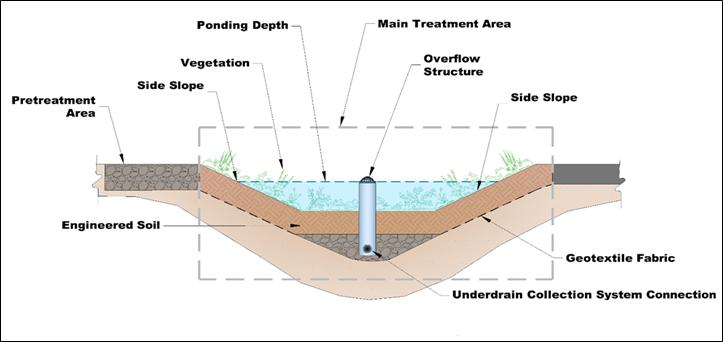
Internal Water Storage not shown Not
Table 5.3.5.1
Design Specifications for the Contributing Drainage Area
Design Element
Drainage Area
Flow Path Slope
Controls for Waste & Other Pollutants
Table
Specification(s)
Maximum contributing drainage area (CDA) = 5 acres; 0.5 to 2.0 acres is preferred
Maximum slope to a swale = 5% .
Appropriate controls shall be included in the design of the contributing drainage area to the SCM to address any wastes and other pollutants (see Table 5.3.3.1 above) that are expected on the property after construction. Use the proposed land use as a guide to determine appropriate controls. Examples of such controls include, but are not limited to, dumpsters, trash cans, covered materials/waste storage areas, covered materials transfer areas, oil and grease waste controls, and pet waste stations.
5.3.5.2 Design Specifications for the Dry Enhanced Swale
Design Element
Infiltration Feasibility Policies
Class V Injection Well Permits
Water Quality Volume (WQv)
Use in a Water Quality Treatment Train
Offline and Online Design Configuration
Specification(s)
Dry enhanced swales shall be designed as a Group 2 SCM (i.e., with an underdrain and internal water storage) unless ALL the following conditions are met.
The SCM will be constructed in uncompacted, native soil that has an infiltration rate between 0.5 and 11 inches/hour, and these soil conditions can be maintained throughout construction of the land development.
Sufficient protection measures to prevent soil compaction within and around the swale after construction are included in the design.
The development and the SCM meets all infiltration feasibility factors established in the Infiltration Feasibility Form provided in Appendix C (Infiltration Feasibility Form).
Infiltration tests are required for Group 1 SCMs before and after swale construction. See Appendix F (Policies for Soil Infiltration Tests & Soil Borings) for infiltration test requirements.
Although unlikely, dry enhanced swales may be subject to a Class V Injection Well Permit pursuant to Tennessee Department of Environment and Conservation (TDEC) rule 0400-45-06-.06. This permit may be avoided by ensuring the swale excavation is wider than it is deep and using a design configuration with an underdrain. Regardless, the requirement for a permit is determined by TDEC, not the local government. When a permit is required, a copy must be provided to the local government prior to, or with, the submission of the Water Quality Management Plan.
The water quality rainfall depth (P) for determination of WQv are as follows:
Dry enhanced swales without an underdrain (Group 1 SCM): P = 1.0 inch
Dry enhanced swales with an underdrain (Group 2 SCM): P = 1.25 inches
Acceptable methods to determine WQv are presented in Chapter 3, Section 3 2.3 (Determining the WQv).
Dry enhanced swales that cannot treat the entire WQv for its contributing drainage area must be used in a treatment train or exchanged with an alternate SCM that can treat required WQv.
If the dry enhanced swale cannot manage the entire WQv for its contributing drainage area, it must be placed in a treatment train with another SCM. See treatment train policies and calculations in Chapter 3, Section 3.2.4 for treatment train policies and calculations.
An online configuration is a common configuration for dry enhanced swales. Online swales are designed and constructed so the main flow path for the drainage area passes through the swale. The swale should be designed to safely convey the peak discharge for the 25-year, 24-hour storm event (Qp25) with a minimum of 6 inches of freeboard without damage to adjacent property.
Design Element
Specification(s)
An offline configuration is designed and constructed away from the main flow path for the drainage area, thus avoiding large flood flows. A flow splitter, diversion structure, or other means is used upstream of the swale’s inlets to redirect the swale’s design volume (typically this will be the WQv) from the main flow path to the SCM while still allowing larger flows to remain in the main flow path. The structure shall include a low-flow orifice, weir, or other hydraulic structure, sized to pass the peak discharge of the design volume (typically this will be the water quality peak discharge, Qwq) to the swale See Section 5.17 (Overflow Controls Design Specification) for the diversion structure sizing design procedure.
Regardless of design configuration (offline or online), dry enhanced swales shall always be located upstream of other SCMs (e.g., detention basins designed for flood control, SCMs in a water quality treatment train, etc.).
The entire dry enhanced swale must be accessible for maintenance without requiring the entry of vehicles or heavy equipment in the swale.
Maintenance Access and Easement
A maintenance easement to (and including) the dry enhanced swale must be provided from a public roadway. The easement must be free of permanently affixed obstructions (e.g., trees, pools, fences without gates, permanent signs, etc.) to allow maintenance vehicles and equipment to safely pass.
Maximum stormwater entry velocity = 5 ft/sec.
Stormwater shall enter the dry enhanced swale as sheet or shallow concentrated flow Energy dissipation measures, such as vegetated buffer strips or rock aprons shall be provided. These measures may also provide stormwater pretreatment
Pretreatment is required immediately below each inlet to remove gross solids, trash, and sediment from stormwater prior to flowing into the main treatment area.
Energy Dissipation & Pretreatment
Vegetated filter strips and gentle side slopes of dense grass are suitable pretreatment measures for lateral non-concentrated inflows. Rock aprons or other methods may be preferred for more concentrated inflows. Pretreatment options and design specifications are provided in Section 5.16 (Inlets, Energy Dissipation, and Pretreatment Measures).
Swales that will receive direct concentrated stormwater may require a 6 inch drop to a pea gravel diaphragm flow spreader at the upstream end of the control to slow and spread runoff entering the swale.
Consider screens, grates, baffles, or other pretreatment measures for debris capture in areas where high amounts of floatables (litter, trash, etc.) is expected.
Longitudinal swale slope = 1% to 2% preferred; 4% maximum.
For slopes greater than 2%, limit the energy slope to the required range of 1% to 2% using drop structures with a vertical height of 6 to 12 inches. Spacing between vertical drops shall be a minimum of 50 feet.
Bottom width = 2 ft minimum; 8 ft maximum.
Swale Slope and Bottom
Side Slopes
Flow Velocity
Bottom lateral slope = 0% (flat)
The WQv must flow evenly across the width of the swale.
Bottom elevation = minimum of 1 foot below the lowest invert elevation of adjacent roadbeds and parking areas.
Ensure the WQv will not bypass or short-circuit the bottom (e.g., inlets or curb cuts that are very close to outlet structures, or incoming flow diverted immediately to the underdrain).
Side slopes = 4:1 or flatter; 2:1 preferred
Maximum peak flow velocity for the 2-year, 24-hour storm event = 5 ft/sec
Design Element
Ponding Depth
Minimum Depth to Water Table
Minimum Hydraulic Head
Drawdown Time
Overflow Structure
Specification(s)
Maximum surface ponding depth at the downstream end = 18 inches
Average surface ponding depth = 12 inches.
Minimum separation distance (bottom of swale to seasonally high-water table) = 2 feet
Soil borings shall be used to determine the seasonally high-water table. See Appendix F (Policies for Soil Infiltration Tests & Soil Borings) for soil boring requirements.
Minimum hydraulic head = 3 to 5 feet.
The hydraulic head is the difference in the inflow elevation, including the design ponding depth, to the outflow elevation at the underdrain invert elevation or bottom of swale at the downstream end
The maximum water ponding time = 48 hours; 24 hours is preferred.
All water shall discharge from the swale within 48 hours.
Dry enhanced swales are typically designed in an online configuration, so they will carry flows well above the WQv. Thus, an overflow structure is typically required at a downstream berm, headwall, or check dam for storms larger than the 25-year, 24-hour event, to allow larger events to safely overflow the swale.
Offline configurations require an overflow design to safely pass runoff that exceeds the swale’s design volume.
The remaining rows specify the subsurface layers of the SCM, starting at the bottom.
Limit the excavation to the width and depth specified in the design.
In-situ Soil
Impermeable Liner Layer
Bottom Stone Layer
Underdrains & Internal Water Storage
Stone Choker Layer
Engineered Soil Mix Layer
If an impermeable liner is not included in the design, scarify the bottom of the excavation to a minimum depth of 6 inches by raking, disking, or tilling prior to placement of SCM layers. The sidewalls shall be uniform with no voids and scarified prior to backfilling.
Trim all large roots on the sides and bottom of the excavation before layers are placed. Place layers in a way that does not cause compaction of the underlying in-situ soil.
An impermeable liner shall be installed on the sides and bottom of swales located where karst terrain is a concern or soil contaminants are known or suspected. Scarification of the in-situ soil is not necessary when an impermeable liner is used.
Swales without an underdrain (Group 1 SCM): 8 inch layer of AASHTO #57 stone (double washed)
Swales with an underdrain (Group 2 SCM): see Section 5.15 (Underdrain & Internal Water Storage).
Upturned elbow underdrain: the bottom stone layer is the same as the “stone jacket” layer specified for the underdrain.
Elevated underdrain: the bottom stone layer is the same as the internal water storage (IWS) layer specified for the underdrain
Swales without an underdrain (Group 1 SCM): An underdrain with IWS is not included in the SCM.
Swales with an underdrain (Group 2 SCM): An underdrain and a minimum of 12 inches of internal water storage must be provided. See Section 5.15 (Underdrain & Internal Water Storage) for specifications.
Swales without an underdrain (Group 1 SCM): 3 inch layer of double-washed AASHTO #8 stone or AASHTO #89 pea gravel placed on the bottom stone layer
Swales with an underdrain (Group 2 SCM): see Section 5.15 (Underdrain & Internal Water Storage).
Minimum depth of the engineered soil mix layer = 30 inches.
Design Element
Specification(s)
Beyond this minimum, the design depth is determined by the design volume (typically this will be the WQv), the geometry of the dry enhanced swale, and plant needs for establishment and longterm root growth.
The engineered soil mix shall be a homogenous mix and meet the standards in the following two tables to provide adequate infiltration, nutrient uptake, and plant support. Material
Medium to coarse washed sand:
Clean, fine soil:
Organic Matter
70-85%
Particle size: 0.050 to 2.0 mm
Silt + clay 10 to 20%, with clay content less than 10%
Clay particle size: < 0.002 mm
Silt particle size: 0.002 to 0.050 mm
5 to 8%
*Animal or poultry manure, at any stage of composition, shall not be used for organic matter content
Magnesium
Phosphorus* (as phosphate P205)
Potassium (K20)
Soluble Salts
AASHTO T88 Standard Method of Test for Particle Size Analysis of Soils
AASHTO T194 Standard Method of Test for Determination of Organic Matter in Soils
to 7.5
Minimum 32 parts per million (ppm)
Maximum 60 ppm as plant available phosphorus
Minimum 78 ppm
Maximum 500 ppm
The volume of engineered soil mix specified and placed shall be based on 110% of the required volume for the SCM to account for settling just after mix placement in the SCM.
Assume an infiltration rate of 2 inches per hour for the engineered soil mix when determining the ponding depth and media depth.
Planting Bed See Section 5.3.7 of this design specification, titled Vegetation Design, for planting bed standards.
5.3.6
Design Procedures
Table 5.3 6.1 provides the design procedure for a dry enhanced swale
Table 5.3.6.1 Design Procedure
Evaluate dry enhanced swale feasibility.
Use the feasibility and location criteria provided in Tables 5.3 5.1 and 5.3 5.2 to determine if a dry enhanced swale is feasible for the selected location on the land development site. Consider especially whether it is appropriate for the proposed development based on the intended land use of the property, the maintenance burden, and assumptions or knowledge of how the landowner(s) will care for the dry enhanced swale (e.g., maintain it themselves, through a property manager, or hiring a landscape
Step
Step 2
Step 3
Step 4
Step 5
Step 6
Step 7
Step 8
Design Activity
contractor). Communicate the requirements for long-term maintenance to the landowner(s) before deciding.
If a dry enhanced swale is determined to be feasible and appropriate for the proposed development, create a rough layout of its dimensions, taking into consideration existing trees, utility lines, and other obstructions to ascertain if it will fit into the desired space, given its general design requirements.
Determine the goals and primary function of the dry enhanced swale.
Consider the purpose(s) of the dry enhanced swale as listed below and design it accordingly:
Comply with the local government stormwater quality requirements (i.e., treat the WQv, provide channel protection, etc.).
Include additional storage capacity for a higher level of stormwater quality treatment or to address a small onsite drainage issue.
Enhance landscape and provide aesthetic qualities.
Calculate the design storage volume (DSv) for the contributing drainage area.
Typically, the DSv = WQv, unless the dry enhanced swale cannot manage the entire WQv.
Use one of the calculation methods explained in Chapter 3 Section 3 2.3 (Determining the WQv) to calculate WQv.
Determine the storage volume of the preliminary layout of the dry enhanced swale.
�������� = �������� +(������������ ���� ����) where:
VP = volume provided in temporary storage (ft3)
PV = ponding volume (ft3), for a maximum ponding depth of 12 to 18 inches at the downstream end of the swale
VES = volume of engineered soil mix (ft3)
n = porosity of the engineered soil mix (most engineered soil has a porosity of 0.25; gravel has a porosity of 0.40)
Determine if the proposed dry enhanced swale meets the WQv requirement.
If VP ≥ WQv, proceed with Step 6.
If VP ≤ WQv, redesign the swale to provide sufficient volume for the WQv and recalculate VP.
Create the swale design.
Size the swale bottom width, depth, length, slope, and side slopes.
Maximum ponding depth is 18 inches.
Longitudinal slope must not exceed 4% (1 to 2% is recommended).
Bottom width should be from 2 to 8 feet.
Side slopes must be no greater than 4:1; 2:1 is preferred.
Full discharge of the swale within 48 hours.
Compute the number of check dams required and their heights to detain the WQv so it infiltrates into the engineered soil mix. All larger storms should flow over the check dams without eroding the swale.
Check for adequate capacity to manage the entire WQv storm.
Route the hydrograph of the water quality storm event through the swale to ensure it captures the entire WQv, even when the WQv includes the peak flow of the water quality storm event.
Group 2 dry enhanced swales only: Design the underdrain.
See Section 5.15 (Underdrains and Infiltration Sumps) for requirements.
Step Design Activity
Step 9
Step 10
Step 11
Step 12
Step 13
Calculate the drawdown time.
The entire WQv must discharge from the swale within 48 hours.
Check the velocity, erosion potential, and freeboard for the 2-year and 25-year, 24-hour storm events.
Modify the design until erosive velocities are eliminated.
Provide 6 inches of freeboard for the 25-year event.
Size the overflow structure (for all swales) and any flow regulators (for offline swales only).
See Section 5.17 (Overflow Controls) for requirements.
Design the pretreatment measures.
See Section 5.16 (Inlets, Energy Dissipation, and Pretreatment Measures) for requirements.
Design the vegetation and protection measures.
The vegetation design shall be in accordance with the vegetation design requirements provided in Table 5.3.7.1. Use guidance found in Section 5.3.9 (below) to design protection measures.
5.3.7 Vegetation Design
Dense, healthy grass is critical to the performance and function of a dry enhanced swale as a water quality treatment SCM. Plants filter and transpire stormwater, providing both pollutant removal and runoff volume reduction. They maintain soil health by preventing erosion and providing organic matter for nutrient replenishment. Further, they function as habitat for surface and subsurface fauna that help keep the engineered soil mix loose and permeable for stormwater infiltration. The importance of plants to dry enhanced swale function means they, like any SCM component, have design, installation, and maintenance specifications. Much of the design and maintenance of a dry enhanced swale centers on plant coverage and replacement. Table 5.3.7.1 provides the vegetation specifications for a dry enhanced swale.
Table 5.3.7.1 Vegetation Design Specifications
Vegetation Design Element
Minimum Coverage
Specification(s)
The entire (100%) surface area of the dry enhanced swale must be covered by dense, healthy grass. Stone/cobbles may be used where grass cannot be reliably established, provided they are sized sufficiently to remain in place during storm events. Areas of bare soil are not allowed in the swale
Shrubs and trees are allowed in the area surrounding the swale but shall not be planted within the channel and shall not be accompanied by, or placed within, mulch beds. (Mulch of any type is prohibited in the swale.) Shrubs and trees are best suited for the upper areas of side slopes or outside the channel entirely to avoid damage (caused by roots) to the engineered soil mix, liner, and underdrain.
To prevent erosion of the bottom and side slopes, vegetation shall be established by sodding the dry enhanced swale with the desired grass species. Seeding is prohibited when installing the swale. Thus, grass coverage of 100% of the swale surface area must be achieved as soon as installation is finished.
A dense and vigorous vegetative cover must be established over any pervious areas located within the contributing drainage area to the swale before runoff is accepted into it. Otherwise, the swale can become clogged with sediment carried by the stormwater runoff discharging to it.
Vegetation Design Element
Plant Survival
Plant Selection
Recommended Signage
Specification(s)
Grass replacement is required when the minimum coverage goal of 100% is not achieved. The use of sod is preferred over seeding to significantly reduce the potential for soil erosion within the swale’s main treatment area.
Select grass for the swale that will:
tolerate cycles of drought and inundation, as these conditions are expected.
root deeply to resist scouring
tolerate salt (for swales that will receive drainage from areas treated for ice in winter).
For guidance on appropriate grass species, consult a plant and landscape expert, such as a landscape architect, local nursery, or Master Gardener from the Tennessee Extension Master Gardener Program (https://mastergardener.tennessee.edu/).
Native grasses may be better suited to local hydrologic conditions.
Grass suitable for United States Department of Agriculture (USDA) Plant Hardiness Zone 6a7a (depending on your zip code) are recommended.
Consider future maintenance needs when selecting grass for the swale. The level of care needed to maintain the grass should influence its selection.
If the swale is covered with turf grass, consider installing signage at the swale advising the use of push mowers or string trimmers only. Commercial mowers can compact the swale bottom and damage the underdrain.
Compliance with the vegetation standards set forth in Table 5.3 7.1 shall be shown in a vegetation plan that is included with the water quality management plan (WQMP) for the property. Requirements are provided below:
The plan must be prepared by a professional qualified in landscape design by their education or experience.
The plan shall include one or more labeled plans/details (to scale) showing the plants to be installed, their numbers, and locations. Plan notes showing a plant schedule and installation instructions are encouraged. This additional information allows both the plant installer at the time of construction, as well as the person(s) responsible for maintenance of the SCM after construction, to understand the original vegetation design and its compliance with the minimum standards.
Landscaped SCMs may not be recognized under the local government’s codes as property landscaping. Therefore, additional requirements for property landscaping may apply.
5.3.8 Protection Design Guidance
SCMs designed for stormwater quality purposes must be maintained in keeping with the approved SCM design for the life of the land development 2 Design professionals can assist property owners with this requirement by including protective features in and around SCMs to limit the potential for damage by external factors. Often, the landscape and impervious features around an SCM can be tailored to its specific needs, and therefore used to protect its critical components.
For dry enhanced swales, protection is especially important for the swale bottom. Encroachments by vehicles, heavy equipment, and pedestrians can kill the grass, compact the engineered soil, and potentially deform or crush the underdrain (if present). The good news is that dry enhanced swales are especially well-suited to a variety of protection methods that can both protect the area and enhance the property’s landscape aesthetic or impervious surface function. Examples of protection measures are shown in Figure 5.3 8.1 Types of protection methods that work well with dry enhanced swales are listed in Table 5.3 8.1
2 Tennessee Rule 0400-40-10-.04
Passive Protection Measures
Natural fencing around the perimeter (e.g., dense, woody, or prickly shrubs or tall grass)
Driveways, sidewalks, or walkways around the SCM
Pedestrian benches on the perimeter
Geometry/sizing to allow maintenance without vehicles/equipment entering the swale
Active Protection Measures
Decorative fencing
Curbs or curb blocks
Hardscaping (cobble, boulder, or block edging; block walls; etc.)
Educational or directive (e.g., no pets) signs
Pet waste stations and trash cans near the SCM
*The list presented in the table is not exhaustive. There may be other possible protection measures.
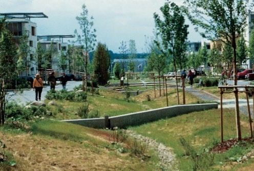

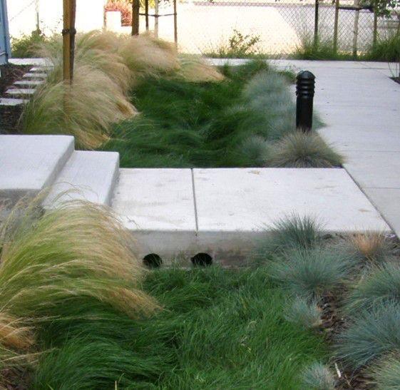
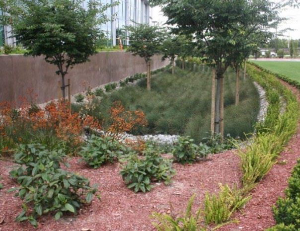
5.3.9 Site Preparation and Land Disturbance Requirements
The following information is provided to support proper and effective construction and protection of dry enhanced swales during land disturbance activities and site construction. Mandatory requirements are identified using “shall” or “must.” All other statements can be regarded as non-mandatory guidance. Site preparation and land disturbance practices described in this section shall be shown on the Erosion Prevention and Sediment Control (EPSC) plan for the proposed land development. Table 5.3.9.1 provides requirements for site preparation and land disturbance practices for land developments with dry enhanced swales
Table 5.3.9.1 Site Preparation and Land Disturbance Requirements for Dry Enhanced Swales
Preservation of the native, uncompacted soil during site construction is critical to the success of the dry enhanced swale. Thus, the following requirements apply:
Dry Enhanced Swale Without an Underdrain (Group 1 SCMs only)
Areas where dry enhanced swales will be located, including a protection zone extending a minimum of 10 feet around the perimeter, shall be protected from entries by vehicles, equipment, and workers during site construction. To the extent practical, work within the perimeter should be confined only to that required for installation of the dry enhanced swale.
The protection zone shall be identified and marked prior to commencement of land disturbance activities using highly visible orange fencing (or similar visible protective measures) and signage to advise construction personnel not to enter the area.
Table 5.3.8.1 Dry Enhanced Swale Protection Measures*
Figure 5.3.8.1 Examples of Dry Enhanced Swale Protection Measures
SCM Type Policy
Left: Passive protection is provided by pedestrian paths along both sides of the swale. (urbanbluegreengrids.com); Middle: a sidewalk allows pedestrians to cross over this thick grass swale (NACTO.org). Right: h decorative landscaping around this grassed dry swale is an example of passive protection. (Duke Farms, Hillsborough, NJ)
Dry Enhanced Swales with an Underdrain (Group 2 SCMs only)
Construction vehicle and equipment parking, thoroughfares, wash-off areas, and sediment traps/basins shall not be located in the dry enhanced swale protection zone.
Clearing, grubbing, and grading using heavy equipment is prohibited in the protection zone. When these activities are necessary for construction of the dry enhanced swale, hand tools or smaller equipment that can reach into the protection zone must be used to avoid compaction of the native soil within the zone.
Dry enhanced swales shall not be used as sediment traps or sediment basins.
Erosion prevention and sediment control (EPSC) measures must safeguard the protection zone both prior to, during, and if necessary, after its installation.
Site construction shall be sequenced such that the swale is installed only after the area draining to it has been fully and permanently stabilized.
Construction phasing and sequencing are critical to the success of Group 2 dry enhanced swales. Thus, the following requirements apply:
Dry enhanced swales can infiltrate stormwater even though they have an underdrain. This capability should be preserved during construction, if possible, by identifying and protecting the swale using highly visible orange fencing (or similar visible protective measures) and signage to advise construction personnel not to enter the area.
Construction vehicle and equipment parking, thoroughfares, and wash-off areas shall not be located where the dry enhanced swale will be located.
When protection from clearing and grading activities is not possible, the dry enhanced swale shall not be excavated lower than two (2) feet above the final design elevation of the bottom of the practice. This prevents further compaction of the soil below the practice by vehicles and heavy equipment. Once the area is excavated to grade, the impacted area must be tilled to a depth of 12 inches below the bottom of the dry enhanced swale.
The dry enhanced swale shall be protected using erosion prevention and sediment control measures before, during, and, if necessary, after installation
Site construction shall be sequenced such that the dry enhanced swale is installed only after the area draining to it has been fully and permanently stabilized.
5.3.10 Installation Requirements
The information in Table 5.3.10.1 provides a typical construction sequence to properly install dry enhanced swales. These steps may be modified to reflect different applications or site conditions. Installation practices shall be shown in the EPSC and WQMP plans, as appropriate for the proposed land development.
Table
5.3.10.1 Installation Steps
Step
Step 1
Requirement
The installation site shall be checked for existing utilities prior to swale construction to avoid potential conflicts and/or damages to utilities.
Construction of the dry enhanced swale shall be performed only after the area draining to it has been fully stabilized to prevent sediment discharges to a newly installed swale and its sensitive plants. Where this requirement cannot be met, a temporary bypass shall be designed to prevent stormwater discharge to the swale until its drainage area is fully stable. It may be necessary to block certain curbs or other inlets while the swale is being constructed.
Step
Step 2
Step 3
Step 4
Step 5
Step 6
Step 7
Step 8
Requirement
Supervision during construction is required to ensure the dry enhanced swale is constructed/installed in accordance with the approved EPSC and WQMP plans. The design professional or a designee under their supervision must inspect the dry enhanced swale at critical stages of construction. Examples of critical stages of construction include protection zone and erosion prevention and sediment control measure installation, excavation, underdrain installation, and final inspection. This ensures that the contractor’s interpretation of the plan is consistent with the design professional’s intentions and allows the design professional to certify (in the as-built plan) that the dry enhanced swale is built in keeping with the permitted plan.
Construction sites can have many different contractors responsible for different portions of the site or aspects of construction. Therefore, subtle differences in site grading, drainage, and paving elevations from those identified in the design, or relative to different areas/aspects of construction, can affect the hydraulics of the proposed dry enhanced swale. The following practices should be done prior to construction to ensure the approved design is still valid:
During the preconstruction meeting, review and confirm that the actual boundaries of the dry enhanced swale’s contributing drainage area and inlet elevations conform with the approved design.
Any changes that result from the preconstruction meeting must be shown as a revision to the approved WQMP and resubmitted to the local government for approval. This includes changes to material certifications for aggregate, the engineer soil mix, and liners if not approved prior to the preconstruction meeting.
Install protection and erosion prevention and sediment control measures as indicated in Table 5.3.9.1 above.
Special protection measures, such as erosion control fabrics, may be necessary to protect vulnerable side slopes from erosion during the construction.
Pretreatment measures shall be excavated first and then sealed to trap sediments prior to installation of the main treatment area.
Excavate the dry enhanced swale to its appropriate design depth and dimensions. Excavators or backhoes, if used, must be located on the sides of the swale, and have adequate reach inside the footprint for full excavation.
For dry enhanced swales without an underdrain, DO NOT allow vehicles or heavy equipment in the protection zone.
For dry enhanced swales with an underdrain, DO NOT allow vehicles or equipment in the swale itself
For excavation of large swales, use a cell construction approach where the area is split into 500- to 1,000 square foot temporary cells with a 10-to-15-foot earth bridge in between. This allows cell excavation from the sides.
Continue to avoid the use of heavy equipment and vehicles in the main treatment area (and protection zone) for the remainder of the steps listed below.
It may be necessary to loosen (rip) the bottom soils to a depth of 6 to 12 inches to promote greater infiltration.
Place liners as specified in Table 5.3.5.2 with a 6 inch overlap at seams
Place the required depth of stone on the bottom, install the perforated underdrain pipe (if part of the plan) and its required stone jacket, and add the choking layer.
Apply the engineered soil mix in 12 inch lifts until the desired top elevation of the dry enhanced swale is achieved.
Step Requirement
Wait a few days to check for settlement and add additional engineered soil mix as needed to achieve the design elevation.
Note: The batch receipt confirming the source of the engineered soil mix must be included with the Record Drawing
Step 9
Step 10
Step 11
Install temporary irrigation measures, if needed, to ensure the grass will be watered during the remainder of site construction.
Install sod or other plants as shown in the approved vegetation plan (see Section 5.3.8 and Table 5.3.7.1 above).
Erosion/sediment control devices can be removed from the inlet once the dry enhanced swale’s side slopes have good vegetative stability, and the drainage area is fully and permanently stabilized. However, if the area draining to the swale includes newly installed asphalt, the erosion/sediment control devices in place to block the inlets should remain for at least three storm events after asphalt installation. A substantial quantity of fine particles and grit are discharged from newly installed asphalt during the first several storms that produce runoff after installation. Maintenance of the swale will be required to remove particles and grit if erosion/sediment control devices are removed too early.
Maintain the dry enhanced swale in keeping with Section 5.3.11 below.
Prepare the Record Drawing and submit it to the local government for review and approval with the engineer’s as-built certification before a temporary or final Certificate of Occupancy can be obtained.
Step 13
5.3.11
Advise the landowner (i.e., the person(s) taking ownership of the property immediately after its development) of the presence of the dry enhanced swale and provide them with a copy of the property’s Record Drawing and SCM location map. The plan must clearly show the location of the swale on the property and list the activities (and their frequencies) necessary for its proper maintenance.
SCM Maintenance on an Active Construction Site
SCM maintenance is regulated by local government ordinances from the moment they are installed. As well, SCMs must pass a final inspection prior to construction termination. This inspection will be performed to ensure they are constructed accordance with the approved WQMP, undamaged, and free of sediment and debris. Thus, SCM maintenance is good practice to ensure construction termination goes smoothly. Relevant policies are as follows:
The property owner is responsible for SCM maintenance. If the property is still an active construction site, these responsibilities may fall to the land disturbance permittee until the project receives final approval from the local government and/or a Certificate of Occupancy.
Property owners may have others, such as a site contractor or landscaping company, maintain the dry enhanced swale on their behalf. However, the local government will hold the property owner responsible for ensuring it is maintained in proper operating condition (i.e., as designed and constructed) regardless of who performs maintenance activities.
Maintenance activities, which include ensuring proper operation of the SCM as designed and required SCM inspections, must begin immediately following installation of the dry enhanced swale
Maintenance activities shall be performed in keeping with the Northeast Tennessee SCM Inspection and Maintenance Manual. Additional guidance on maintenance of newly dry enhanced swales areas located on active construction sites is provided in Table 5.3.11.1.
Table 5.3.11.1
Post-Installation Maintenance Activities
Contributing Drainage Area
Dry Enhanced Swale
Education
Keep the area draining to the SCM clean. Sweep trash, debris, and sediment frequently so that it does not wash in the swale during a rain event.
The area should be fully stabilized before the installation of the SCM. If it is not, prevent inflows to the SCM by blocking or using diversion measures until the contributing drainage area is fully stabilized. Stabilize the area as soon as possible to prevent the discharge of sediment to the SCM.
Cover stockpiles of construction and landscape materials to prevent their exposure to rainfall.
Ensure the grass is watered and growing as expected.
Remove and replace diseased, dying, or dead patches of grass as soon as they are noticed.
Ensure the swale remains free of sediment and wastes.
Ensure vehicles, equipment, and people are not allowed in the swale. Evidence of unwanted entries include tire tracks or footprints, stone displacement, or damage to components or vegetation
Immediately determine and eliminate the cause and repair the area. Consider installing fencing.
Visually observe swale function after rain events; there should be no standing water within 48 to 72 hours after a storm event, depending on the frequency of rainfall. If long-standing water is observed:
Inspect underdrain via the observation well looking for standing water indicative of a blockage or damage; make repairs if needed.
If underdrain/outlet blockages and damage can be ruled out, then the engineered soil mix may be clogged. This repair requires soil removal, underdrain cleaning, and reinstallation of the main treatment area; consult the design engineer.
Inspect the swale for erosion or significant sediment buildup; immediately determine and eliminate the cause and repair the area.
Alert onsite subcontractors to the SCM and the following requirements:
No muddy vehicles or equipment in the drainage area to the swale.
No stockpiling of material in the swale and no exposed stockpiles in the swale’s drainage area.
Block inlets prior to asphalt placement in the drainage area.
Remove sediment, trash, debris, and empty trash cans frequently.
Advise landscaping subcontractors on proper protection and maintenance of the dry enhanced swale, especially the following:
No heavy equipment, including commercial mowers (push mowers or string trimmers only).
No dumping of lawn clippings or landscape debris
Plant maintenance needs/requirements (see above).
5.3.12 References
ARC. Georgia Stormwater Management Manual Volume 2 Technical Handbook, 2016 Edition. Atlanta Regional Commission, 2016
Chesapeake Stormwater Network (CSN). 2008. Technical Bulletin 1: Stormwater Design Guidelines for Karst Terrain in the Chesapeake Bay Watershed. Version 1.0. Baltimore, MD. Available online at: http://chesapeakestormwater.net/2012/03/technical-bulletin-no-1-stormwater-design-guidelines-for-karstterrain/ Area or Component
CWP. 2007. National Pollutant Removal Performance Database, Version 3.0. Center for Watershed Protection, Ellicott City, MD.
CDM. 2000. Metropolitan Nashville and Davidson County Stormwater Management Manual Volume 4 Best Management Practices.
Federal Highway Administration (FHWA), United States Department of Transportation. Stormwater Best Management Practices in an Ultra-Urban Setting: Selection and Monitoring. Accessed January 2006. http://www.fhwa.dot.gov/environment/ultraurb/index.htm.
MWS 2021. Metropolitan Nashville-Davidson County Stormwater Management Manual Volume 5 Low Impact Development. Metro Water Services. Nashville, TN.
VADCR. 2011. Stormwater Design Specification No. 8: Infiltration, Version 1.9, March 1, 2011. Virginia Department of Conservation and Recreation. Available at: http://vwrrc.vt.edu/swc/NonProprietaryBMPs.html.
5.4 Conventional & Dry ED Basin
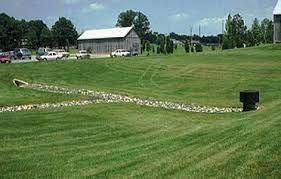
Water Quality Volume (WQv) Rainfall
Group 3 Design
P = 2.5 inches or the first 75% of the volume of the 1-yr, 24-hr storm, whichever is less
OTHER SCM ATTRIBUTES
Overview
A conventional detention basin is an above-ground storage facility that provides water quantity (i.e., flood) control through temporary detention of stormwater. A dry extended detention (ED) basin is a variant of the conventional design that also provides stormwater quality control by extending the storage time of the WQv. Pollutants in the WQv settle to the basin bottom and cleaner water is released downstream. Because conventional detention basins require an upstream SCM for water quality treatment, they are not included in SCM Groups 1 through 4. In contrast, dry ED basins are a Group 3 SCM and do not require an upstream SCM for water quality treatment when properly sized (Photo credit: Hamilton County, TN)
ADVANTAGES/BENEFITS
High community acceptance and understanding
Can have a pleasing aesthetic with surrounding landscaping
Channel Protection Volume (CPv) Yes
(cost scale is $-low, $$- medium, $$$-high)
Detention / Retention Control Yes
Small Storm Local Flood Control Yes
Typical SCM Footprint Size (percent of contributing drainage area)
Easy to maintain if sited and designed with maintenance in mind (i.e., sited as maintained open space without steep, rip-rap slopes)
Can provide multiple functions during dry periods (e.g., recreation)
DISADVANTAGES/LIMITATIONS
Large size relative to other SCMs
Poor siting and design can contribute to owner neglect
Dam height restrictions may apply in high relief areas
Basin drainage can be problematic for low relief terrain
LOCATION, SIZING, & COMPONENTS
Depth should not exceed 10 feet
Sediment forebays required at all inlets
Typical outlet configuration is a multi-stage riser
Emergency spillway/overflow required
LONG-TERM PROTECTION
Primary concerns are slope protection and damaged/clogged outlets
Secure outlet(s) to prevent entry by children
LONG-TERM MAINTENANCE
Primary routine maintenance activities will be inlet, pretreatment device and outlet cleaning, and plant care (e.g., mowing, removal of woody vegetation, pruning, leaf, and landscape debris removal)
Smaller outlets require frequent cleaning to prevent clogging
Consider permanent signs to dissuade use of SCM as a pet relief area
Maintenance is often neglected by property owners, especially when located in a remote or isolated area of a property
Northeast Tennessee Water Quality SCM
5.4.1
General Description
Generally, detention basins are stormwater control measures (SCMs) that provide for the temporary, above-ground storage of stormwater (see Figure 5.4.1.1). Stored water is released at controlled rates of discharges via an outlet structure at the downstream end of the basin. The structure has one or more openings (usually orifices or weir notches) along its vertical length and is often open at the top (see Figure 5.4.1.2) Each opening is designed to control the rate of stormwater discharges from the outlet structure in keeping with local government requirements. The outlet structure typically discharges to a stormwater conveyance system (onsite or public) or a local stream.
Figure 5.4.1.1 Examples of Extended Dry Detention Basin Applications
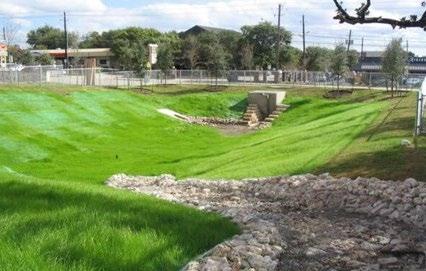

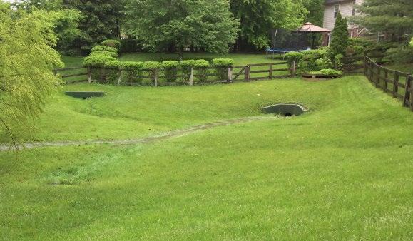
5.4.2
Design Applications
Generally, detention basins are one of the most commonly employed stormwater management techniques. While they may not always be suitable for highly urbanized developments because of their relatively large areal footprint, they possess relatively few other limitations Some minor design modifications may be necessary for developments with obvious karst topography.
Conventional detention basins and dry ED basins differ in the local government stormwater management standards each can address, as follows.
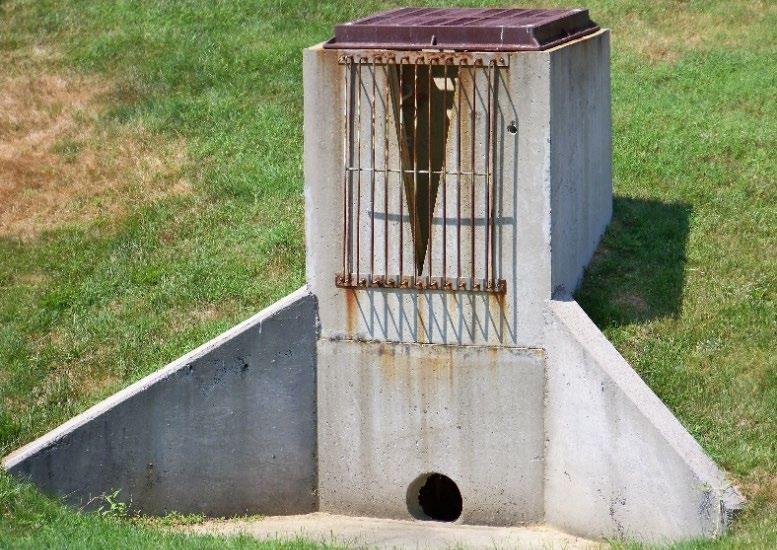
Top left: City of White House, TN; Top right: Clermont OH Soil & Water Conservation District; Bottom left and right: Detention basin used as recreational fields in Great Falls, MT during a dry period (left) and after a large storm (right), TDH Engineering.
Same detention basin
Figure 5.4.1 .2 Example of a Multi-Stage Outlet Structure
Water Quality Volume (WQv) – Conventional detention basins are not designed to detain the WQv and therefore are not included in an SCM Group. One or more upstream SCMs from SCM Groups 1, 2, 3, or 4 are required to provide stormwater quality treatment.
As a Group 3 SCM, dry ED basins are designed to detain the WQv. Suspended sediments and other pollutants are removed from the WQv by gravitational settling during the water detention period before it is discharged through the outlet structure. The basin must be properly maintained to prevent resuspension of deposited sediments.
Channel Protection Volume (CPv) – Both conventional detention basins and dry ED basins can be designed to provide extended detention of the CPv (i.e., the runoff volume from the 1-year, 24-hour storm). For a conventional detention basin, a CPv outlet will need to be included in the design of the outlet structure. However, dry ED basins that are designed to provide extended detention of the entire WQv for its contributing drainage area meet local government channel protection requirements without further design effort. See Chapter 3 (Standards, Methods, and SCM Selection) for more information.
Flood Protection (Qp) – Both conventional detention basins and dry ED basins can be designed to provide flood protection.
5.4.3 SCM Suitability
Use Table 5.4.3.1 to determine if a detention basin is suitable for the application being considered. Note: the criteria pertain to both conventional detention and dry ED basins (generally, “detention basins”), unless one or the other is explicitly named
Table 5.4.3.1 Suitability Factors
Stormwater Quality
Treatment
Channel Protection
Conventional detention basins, as defined herein, do not satisfy local government stormwater water quality treatment standards.
Dry ED basins designed in keeping with the specifications established herein will satisfy local government water quality treatment standards.
Detention basins can be designed to satisfy local government channel protection standards. However, dry ED basins sized to manage the entire WQv, as described in Chapter 3 (Standards, Methods, and SCM Selection), will meet the CPv standard without the need for additional design. If the basin cannot retain the entire WQv, then the CPv standard is not met.
Detention
Pollutant
Treatment
Capability
Detention basins can be designed to satisfy local government peak discharge (flood) control requirements
Dry ED basins designed in keeping with the specifications established herein can address the following common stormwater pollutants:
Northeast
Treatment of Waste and Other Pollutants
Detention basins shall not be used to treat wastes and other pollutants, many types of which are listed below, should they be present in the contributing drainage area to the basin:
Construction sediment/waste
Landscape storage or waste
Sewage, pet, and livestock waste
Medical waste
Household & commercial wastes
Hazardous wastes
Gasoline, motor oils, greases, and other petroleum-based products
Fats, oils & grease (from food preparation)
Pesticides, fertilizers, herbicides
Other byproducts and waste materials expected, based on the property’s land use
Privately owned detention basins are not allowed in the public right-of-way.
General suitability criteria by land-use type is as follows. See Chapter 3 (Standards, Methods, and SCM Selection) for more information.
Suitability by Land Use
5.4.4
SCM Location Requirements
Location constraints for detention basins are provided in Table 5.4.4.1. Note: the criteria pertain to both conventional detention and dry ED basins (generally, “detention basins”) unless one or the other is explicitly named.
Table 5.4.4.1 Dry Extended Detention Basin Location Requirements
*These policies do not preclude the use of dry ED basins on individually owned single family or multi-family residential lots. However, basins placed on residential lots will not be considered by the local government as suitable for compliance with local government stormwater management requirements due to the inherent difficulties in oversight and enforcement of long-term protection and maintenance requirements on residential lots Physical
Minimum setbacks, measured from the outer limit of the basin, are as follows:
15 feet from habitable structures. The first floor elevation for any structure adjacent to the basin shall have an elevation no lower than 1 foot above the top of the berm
SCM Setbacks
50 feet from private water supply wells.
50 feet from a septic tank/leach field.
TDEC specified distance per designated category from public water supply reservoirs
Detention basins shall not be located where they will receive inflows from sump pumps, wash stations, or other non-stormwater discharges.
Flow Avoidance
Utility Avoidance
Avoid locating detention basins where they will receive continuous or dry weather inflows from springs and seeps.
Detention basins shall not be located above underground dry utility lines (electric, cable, and telephone) and water/wastewater infrastructure.
Design professionals must consult the local utility to determine the horizontal and vertical clearance required between SCMs and dry and wet utility lines.
Northeast Tennessee Water Quality
5.4.5 Design Requirements
Figure 5.4.5.1 presents a general layout of a dry ED basin.
The criteria provided in Tables 5.4.5.1 and 5.4.5.2 shall be considered minimum standards and specifications for the design of detention basins and their contributing drainage areas These criteria shall be applied unless stated otherwise Note: the criteria pertain to both conventional detention and dry ED basins (generally, “detention basins”) unless one or the other is explicitly named.
5.4.5.1 Schematic of a Dry ED Basin
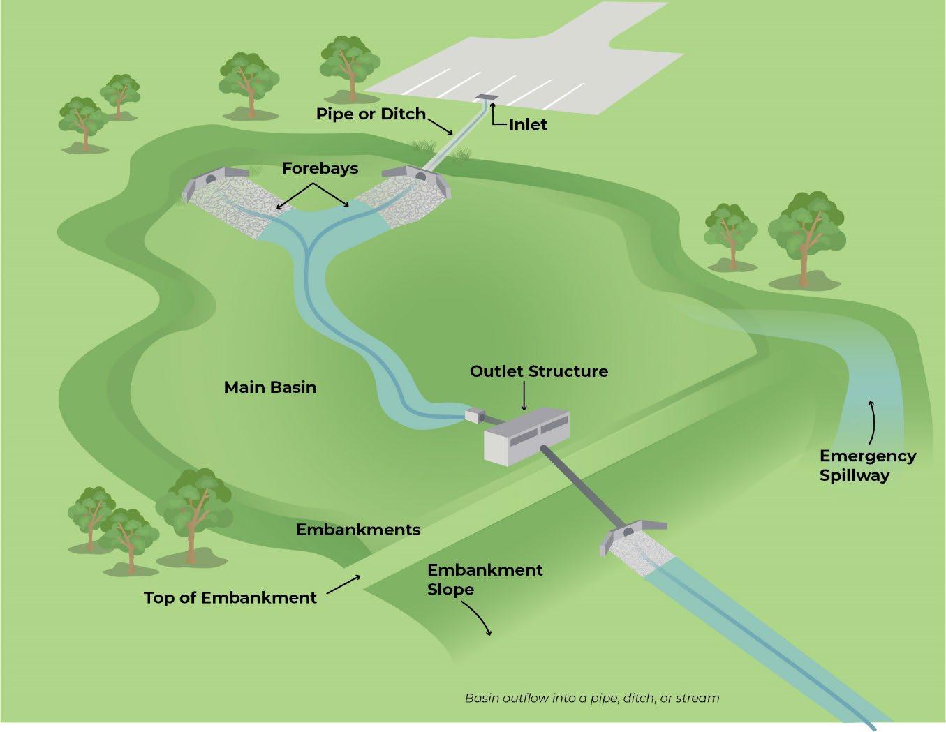
Table 5.4.5.1 Design Specifications for the Contributing Drainage Area
Design Element
Size
Specification(s)
Generally, no restrictions; however, the local government may impose a size restriction for very large contributing drainage areas to control the size of the detention basin. In this situation, multiple detention basins may be used.
Slope Contributing drainage area slope cannot exceed 1 5%.
Figure
Northeast
Design Element
Controls for Waste & Other Pollutants
Specification(s)
Appropriate controls shall be included in the design of the contributing drainage area to the SCM to address any wastes and other pollutants that are expected on the property after construction (see Treatment of Waste and Other Pollutants in Table 5.4.3.1 above) Use the proposed land use as a guide to determine appropriate controls. Examples of such controls include, but are not limited to, dumpsters, trash cans, covered materials/waste storage areas, covered materials transfer areas, oil and grease waste controls, and pet waste stations.
Table 5.4.5.2 Design Specifications for Detention Basins
Design Element
Water Quality Volume (WQv)
(Dry ED basins only)
Use in a Water Quality Treatment Train
(Dry ED basins only)
Drawdown Time
Energy Dissipation and Pretreatment
Specification(s)
The water quality rainfall depth (P) for determination of WQv is P = 2.5 inches, or the WQv is the first 75% of the volume of the 1-yr, 24-hr storm, whichever is less The design professional can select which volume to use.
Acceptable methods to determine WQv are presented in Chapter 3 (Standards, Methods, and SCM Selection).
Dry ED basins that cannot treat the entire WQv for its contributing drainage area must be used in a treatment train or replaced with an alternate SCM that can treat the entire WQv.
If the dry ED basin cannot manage the entire WQv for its contributing drainage area, it must be placed in a treatment train with another SCM. See treatment train policies and calculations in Chapter 3, Section 3.2.4 for treatment train policies and calculations.
Dry ED basins shall be designed to discharge the WQv fully within 48 hours after completion of a rain event using the orifice sizing guidance presented in Chapter 3 (Standards, Methods, and SCM Selection).
Note: the preferred minimum orifice size is 3 inches. If a smaller orifice is required, provide orifice anti-clogging protection with an over-perforated vertical standpipe with ½-inch orifices or slots that are protected by wirecloth and a stone filtering jacket. Adjustable slide gates can also be used to achieve this equivalent diameter, however anti-clogging must be provided
There are no restrictions on drawdown time for flood control storm events. Consult local government regulations regarding design storms and release rates.
Inflow channels shall be stabilized with flared riprap aprons or the equivalent to slow water to nonerosive velocities (maximum of 5 ft/sec)
A sediment forebay shall be provided immediately downstream of each inlet in both conventional detention and dry ED basins.
Forebays shall be sized to hold a minimum of 10% of the WQv of the basin Forebay volume can be considered as part of the WQv, not additional volume of the basin.
When determining forebay geometry, greater depth (ideally 4 to 6 feet) is preferred over greater width. This allows the forebay to dissipate turbulent inflows without resuspending previously deposited sediment; however, safety concerns and ease of maintenance must be considered when designing sediment forebays.
Other pretreatment devices (e.g., MTDs, filter strips, etc.) cannot be substituted for sediment forebays; however, basins that are expected to readily encounter litter, leaves, and other floatables should include screens, grates, or other measures at the forebay discharge points to reduce floatable entry into the main basin.
Design Element
Geometry
Ponding Depth
Minimum Depth to Water Table
Basin Bottom
Embankments (including the dam)
Storage Capacity
Specification(s)
Designing dry ED basins with a high length to width ratio (i.e., at least 1.5:1) and incorporating other design features to maximize the flow path effectively increases the detention time in the system by eliminating the potential of flow to short circuit the basin. Designing basins with relatively flat side slopes can also help to lengthen the effective flow path.
Maximum ponding depth = 10 feet.
The bottom of the basin shall not intersect the groundwater table.
A separation distance of 2 feet from the bottom of the basin to the seasonally high-water table may be required for detention basins located in a stormwater hotspot area or an area with known soil contamination. An impermeable liner below the basin may also be required. Hotspot designation is determined by the local government.
Soil borings shall be used to determine the seasonally high-water table. See Appendix F (Policies for Soil Infiltration Tests & Soil Borings) for soil boring requirements.
Bottom slopes must be between 2% and 4% and graded toward the outlet structure.
A low-flow channel may be designed across the facility bottom from the inlet to the outlet to convey low flows and prevent standing water after smaller storm events.
Conventional detention basin: Channel lining can be grass, riprap, or concrete.
Dry ED basin: Channel lining must be dense grass, with optional riprap placed on the sides of the channel.
Careful finish grading is required to avoid the creation of surface depressions upland of the outlet structure that may cause standing water
Preferred maximum height = 20 feet.
All embankments and spillways shall be designed to TDEC rules and regulations as applied to the Safe Dams Act of 1973, where applicable.
Embankments shall provide a minimum of 1-foot of freeboard
Preferred maximum embankment/dam slope is 3:1 ( h:v); 2:1 slopes or higher may be allowed where a lower slope cannot be reasonably achieved.
Benching is required if the slope is greater 2:1 and the embankment is higher than 10 feet.
In this case, a geotechnical slope stability analysis and stability engineering (if necessary) is mandatory
Areas external to the embankments (surrounding the detention basin) that are above the normal high-water elevation of the basin shall be sloped toward the basin to prevent standing water. Careful finish grading is necessary to avoid the creation of upland surface depressions that may retain runoff.
A minimum of 1 foot of freeboard shall be provided, measured from the top of the water surface elevation for the extreme flood to the lowest point of the dam embankment, not counting the emergency spillway.
Designs for basins that impound more than 30 acre-feet of water shall adhere to the Tennessee Safe Dams Act.
Routing calculations must demonstrate that the storage volume of the detention basin is adequate (not including freeboard) for all design storms. See Chapter 3 (Standards, Methods, and SCM Selection) for more information on storage design requirements.
Outlet Structure Outlet risers shall be located within the basin embankment for maintenance access and safety.
Design Element
Emergency Spillway
Safety Features
Ground Cover
Maintenance Access and Easement
Specification(s)
For detention basins that discharge directly to a mapped floodplain, the downstream invert elevation of the outlet barrel shall be at least 1-foot above the base flood elevation.
For detention basins that discharge directly to an unmapped stream or waterbody (e.g., stream or lake), the downstream invert elevation of the outlet barrel shall be at least 1-foot above the elevation of the edge of bank (for a stream) or normal pool elevation (for a lake)
For additional requirements to those listed in this row, see Chapter 3, Section 3.5 (Storage Facility Outlet Structures).
Water shall not be discharged from a dry ED basin in an erosive manner. Riprap, plunge pads or pools, or other energy dissipators shall be placed at the outlet of the barrel to prevent scouring and erosion. If a basin outlet discharges immediately to a channel that carries dry weather flow, care should be taken to minimize disturbance along the downstream channel and streambanks, and to reestablish a forested riparian zone in the shortest possible distance (if the downstream area is located in a water quality buffer).
All outlet structures shall be designed so as not to permit access by children.
An emergency spillway shall designed to safely pass the peak discharge of the 100-year, 24-hour storm event without negative impacts to downstream structures.
The emergency spillway shall be located a minimum 0.1 foot above the 100-year water surface elevation.
A safety bench shall be provided for embankments greater than 10 feet in height and having greater than a 3:1 side slope. For large basins, the safety bench shall extend no less than 15 feet outward from the normal water edge to the toe of the basin side slope. The slope of the safety bench shall not exceed 6%.
The property owner may consider fencing the basin for the purpose of safety management if the basin is not designed for recreational use during dry weather
The posting of warning signs near the basin to prohibit swimming and fishing in the facility is highly encouraged
See Section 5.4.7 below for detention basin vegetation standards.
A maintenance easement shall be provided to the basin from a driveway, public or private road. It shall be designed as follows:
a minimum width of 20 feet.
a maximum slope of no more than 15%.
a minimum drive path having a width of 12 feet free of permanently affixed obstructions (e.g., trees, pools, fences without gates, permanent signs, etc.) and appropriately stabilized to withstand maintenance equipment and vehicles
to the extent feasible, allow vehicles to turn around.
The entire detention basin, (including inlets, pretreatment devices, the storage area. embankments, outlet structure, and emergency spillway) shall be defined at the outer edge of the safety bench, or a minimum of 15 feet from the normal waer pool elevation (measured perpendicular from th epool elevation boundary) if a safety bench is not included in the pond desgn.
Access to the riser should be provided by lockable manhole covers, and manhole steps within easy reach of valves and other controls.
Northeast Tennessee Water Quality
5.4.6 Design Procedure
Table 5.4.6.1 provides the design procedure for a detention basin
Table 5.4.6.1 Design Procedure
Step Design Activity
Evaluate basin feasibility for control of WQv and CPv.
Step 1
Step 2
Conventional detention basins are often required by the local government for flood control purposes. However, design professionals should use the feasibility criteria provided in Tables 5.4.5.1 and 5.4.5.2 t o determine if upgrading a conventional detention basin design to a dry ED basin design is appropriate for stormwater quality control (WQv) and channel protection (CPv). Consider maintenance requirements (e.g., self-maintenance, property/facilities management maintenance, landscape contractor). If possible, include the property owner(s) in SCM selection since they will be responsible for maintenance.
If a dry ED basin is determined to be feasible and appropriate for the proposed development, create a rough layout of its dimensions, taking into consideration existing trees, utility lines, and other obstructions to ascertain if it will fit into the desired space, given its general design requirements.
Determine the goals and primary function of the basin.
Consider whether the intention is to:
Comply with the local government stormwater quality requirements (i.e., treat the WQv, provide, flood control, or include additional storage capacity for a higher level of stormwater quality treatment or to address a small onsite drainage issue.
Enhance landscape and provide aesthetic qualities.
Determine basin location and preliminary geometry.
Step 3
Step 4
This step involves initially designing the grading of the basin (rough contours, including the safety bench if needed), and determining the probable locations of inlets, the outlet structure, its discharge, and the emergency spillway Evaluate the side slopes, depth, and available storage volumes.
Design the basin for WQv and (if required) CPv control.
Note: the preferred minimum orifice size is 3 inches. If a smaller orifice is required, provide internal orifice protection with an over-perforated vertical standpipe with ½-inch orifices or slots that are protected by wirecloth and a stone filtering jacket. Adjustable slide gates can also be used to achieve this equivalent diameter, however anti-clogging protection must be provided
Set up a stage-storage-discharge relationship for the control structure as follows
Use the hydrologic methods established in Chapter 3 (Standards, Methods, and SCM Selection) to determine the WQv for the basin’s contributing drainage area. If the entire WQv can be managed by the basin, no additional design is required for CPv control.
Calculate the WQv orifice release rates and size for extended detention of 48 hours The orifice elevation is determined via the stage-storage-discharge relationship
Design the basin for flood control.
Consult local government requirements for flood control standards (e.g., post-development peak discharge shall not exceed pre-development peak discharge), as well as the required design storms, data requirements, and hydrologic methods for peak discharge determination.
Step 5
Calculate the flood control peak discharges (Qp) and water surface elevations, completing the design of orifices on the detention outlet riser/box.
Size the emergency spillway based on local government requirements for design storm, freeboard, and embankment slopes and elevations. Typically, the invert elevation of the emergency spillway 0.1 foot above the largest design storm’s water surface elevation.
Step Design Activity
Determine the pretreatment volume and design the sediment forebay(s).
Step 6
Step 7
Step 8
Sediment forebays are required at each inlet and must manage a minimum of 10% of the WQv. For ponds that have multiple inlets, determine the volume/sizing of each forebay based on expected inflow volumes at each inlet, ensuring that, together, the forebays will comply with the 10% requirement.
See Section 5.16 (Inlets, Energy Dissipation, and Pretreatment Measures) for more information.
If needed, design screens, grates, or other treatment devices to keep floatables from discharging from the forebay to the main basin.
Design inlets, outlet structures, maintenance access, and safety features.
See Table 5.4.4.2 for more details.
Design the vegetation and protection measures.
The vegetation design shall be in accordance with the vegetation design requirements provided in Table 5.4.7.1
Use guidance found in Section 5.4.8 (below) to design protection measures.
5.4.7 Vegetation Design Requirements
Turf grass or other non-woody ground cover are critical to detention basins, primarily to prevent erosion on the embankments and basin bottom. For a dry ED basin, vegetation also serves as a means of filtering low flows. Table 5.4.7.1 provides the vegetation specifications for detention basins.
Table 5.4.7.1 Vegetation Design Specifications
Vegetation Design Element
Minimum Coverage
Plant Survival
Plant Selection
Specification(s)
All pervious areas of the basin, including bottom, embankment, and interior and exterior of berms, shall be 100% stabilized with a thick stand of turf grass or similar non-woody, dense, vegetated ground cover to prevent soil erosion and provide filtration of low flows. Native vegetation is preferred.
Shrubs and trees are not encouraged due to potential issues with basin damage and maintenance but are allowed in limited numbers (approximately 1 tree per 10,000 ft2)
Riprap, if used, may be used for energy dissipation downstream of inlets and in forebays, and to stabilize steep slopes When used, ensure riprap will not impede basin maintenance
Mulch, wood chips, and other loose (unanchored) soil stabilization materials are prohibited.
Grass replacement with sod is required when the minimum coverage goal of 100% is not achieved.
Tree/shrub replacement is not required.
Grass must be resistant to cycles of drought and inundation, as both conditions will occur. For guidance on appropriate grass species, consult a plant and landscape expert, such as a landscape architect, local nursery, or Master Gardener from the Tennessee Extension Master Gardener program. (https://mastergardener.tennessee.edu/)
Native grasses better suited to local hydrologic conditions are recommended, provided a thick stand can be maintained
Grass suitable for United States Department of Agriculture Plant Hardiness Zoned 6b and 7a (depending on your zip code) are recommended.
Northeast Tennessee Water Quality SCM
Vegetation Design Element
Specification(s)
Deciduous trees and shrubs are strongly discouraged. Consider future maintenance needs of shrubs and trees, if used, when designing the basin. The level of plant care needed to maintain the landscape and their potential impacts on the maintenance of basin components should influence their selection to minimize care needs as much as possible. Potential long-term maintenance issues associated with shrubs and trees include poor grass growth, outlet clogging due to leave/debris drop, and root damage to embankments and components. Future property owners will need to deal with all of these issues. See also shrub/tree location requirements in “Plant Location” row below.
Plant Location
Trees and shrubs, if used, shall not be planted within 15 feet of the toe of an embankment and 25 feet from the principal spillway structure. They are not allowed on the dam or the embankments and are strongly discouraged on the basin floor.
Compliance with the vegetation standards set forth in Table 5.4.7.1 shall be shown in a vegetation plan that is included with the water quality management plan (WQMP). Plan preparation requirements are below.
The plan shall include one or more labeled plans/details (to scale) showing the plants to be installed, their numbers, and locations. Plan notes showing a plant schedule and installation instructions are encouraged. This additional information allows both the plant installer at the time of construction, as well as the person(s) responsible for maintenance of the SCM after construction, to understand the original vegetation design and its compliance with the minimum standards.
Landscaped SCMs may not be recognized under the local government’s codes as property landscaping. Therefore, additional requirements for property landscaping may apply.
5.4.8 Protection Design Guidance
For dry ED basins, protection is especially important for the outlet structure, which present a safety hazard. Use grates, screens, locks, and other protective equipment to prevent tampering and entry. Consult with the local government for fencing and other protective requirements, if any. Figure 5.4.8.1 shows examples of protected basins.
5.4.9 SCM Maintenance on an Active Construction Site
SCM maintenance is regulated by local government ordinance from the moment they are installed. As well, SCMs must pass a final inspection prior to construction termination. This inspection will be performed to ensure they are constructed in accordance with the approved WQMP, undamaged, and free of construction sediment and debris. Thus, SCM maintenance is good practice to ensure construction termination goes smoothly. Relevant policies are as follows:
The property owner is responsible for SCM maintenance. If the property is still an active construction site, these responsibilities may fall to the land disturbance permittee until the project receives final approval from the local government and/or a Certificate of Occupancy.
Property owners may have others, such as a site contractor or landscaping company, maintain the basin on their behalf. However, the local government will hold the property owner responsible for ensuring it is maintained in proper operating condition (i.e., as designed and constructed) regardless of who performs maintenance activities.
Maintenance activities, which include ensuring proper operation of the SCM as designed and required SCM inspections, must begin immediately following installation of the dry ED basin.
Maintenance activities shall be performed in keeping with the Northeast Tennessee SCM Inspection and Maintenance Manual. Additional guidance on the maintenance of a newly installed dry ED basin once it is constructed in its permanent (post-construction) state (i.e., no longer used as a sediment basin/trap) located on active construction sites, is provided in Table 5.4.9.1
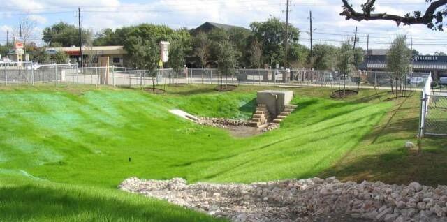
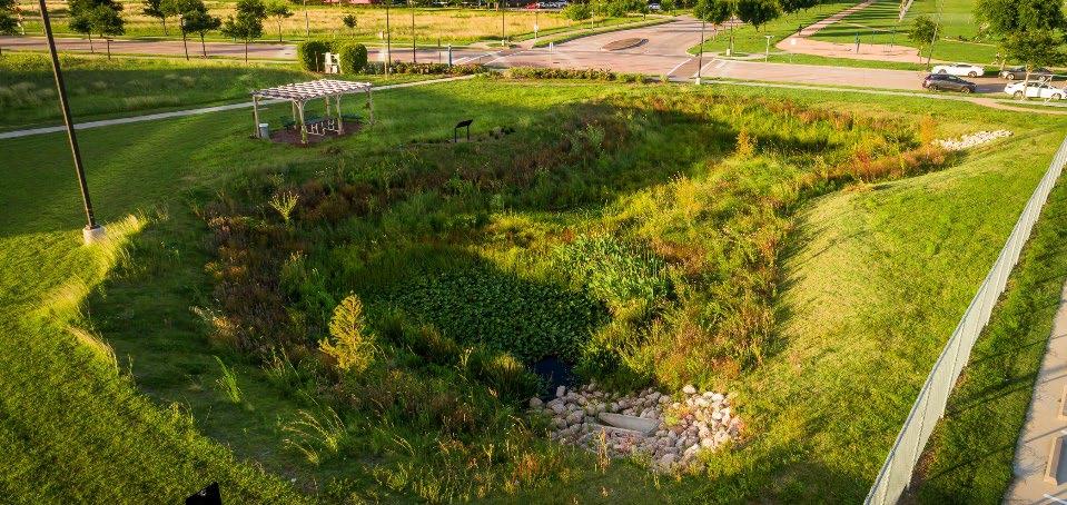
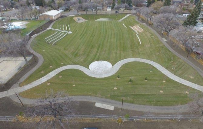
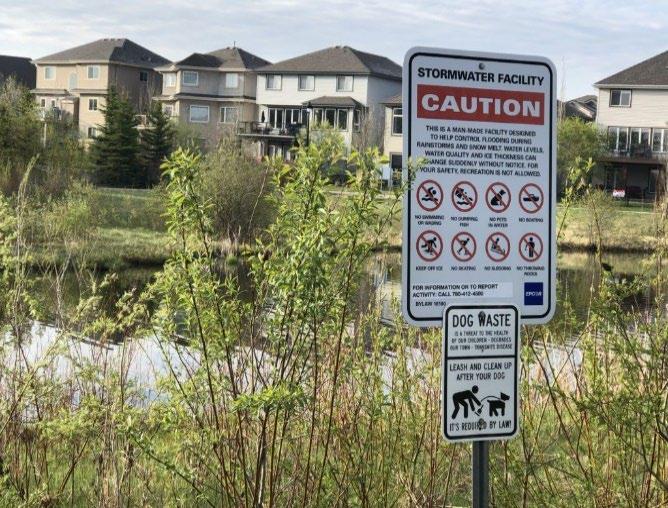
Table
5.4.9.1 Maintenance Activities for Newly Installed Dry Extended Detention Basins
Area or Component
Contributing Drainage Area
Basin
Education
Post-Installation Maintenance Requirement
Keep the contributing drainage area clean. Sweep trash, debris, and sediment frequently so that it does not wash in the basin during a rain event.
Stabilize the area as soon as possible to prevent the discharge of sediment to the SCM
Cover stockpiles of construction and landscape materials to prevent their exposure to rainfall.
Ensure the grass is watered and growing as expected.
Remove and replace diseased, dying, or dead grass as soon as they are noticed. Remove unwanted plants, especially fast-growing vines such as English Ivy and Kudzu to prevent damage to the basin
Clean the sediment forebay as often as needed to prevent inflows of sediment and debris
Inspect the area for erosion or significant sediment buildup; eliminate the cause and repair the area.
Alert onsite subcontractors to the SCM and the following requirements:
No muddy vehicles or equipment in the drainage area to the basin.
No stockpiling or dumping of material, including landscape debris and grass clippings, in the basin, and no exposed stockpiles in the basin’s drainage area.
Remove sediment, trash, debris, and empty trash cans frequently.
Figure
Top Left: Fencing can be installed around a basin’s permitter (City of White House, TN); Top Right: Some basins are designed for dual purposes. This basin is used as a recreational area. (Sacramento State University); Bottom Right: Safety signage installed at a detention basin in Edmonton, AB, Canada (Jolyn Hall, Schmidt Realty Group, Inc ); Bottom Left: Landscaping can deter people and vehicles from entering a detention basin in Houston, TX (photo: Bryan Malloch).
Northeast
5.4.10 References
ARC. Georgia Stormwater Management Manual Volume 2 Technical Handbook, 2016 Edition. Atlanta Regional Commission, 2016
SCM Group: 1
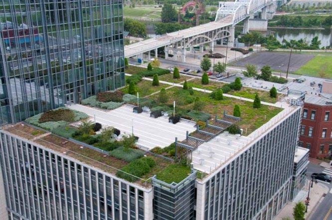
Overview
A green roof is a layer of vegetation installed on top of a conventional flat or slightly sloped roof that consists of waterproofing material, root barrier, permeable filter fabric, growing media, and specially selected plants. (Photo courtesy of Metro Water Services of Nashville and Davidson County, Tennessee)
ADVANTAGES/BENEFITS
Reduce post-construction stormwater volumes and pollutant loads without consuming valuable land
Particularly well-suited for urban developments
DISADVANTAGES/LIMITATIONS
Cost may be greater than a conventional roof
Requires more maintenance than a conventional roof
Only captures and treats stormwater that falls on the roof
DESIGN CONSIDERATIONS FOR LOCATION, SIZING, & COMPONENTS
Comply with the ASTM International Green Roof Standards
Structural load-bearing capacity of the roof
Roof pitch, access, and type
Existing roof equipment and access, available space
Green roofs may be installed on rooftops with slopes of up to 25% but are not generally recommended for use on rooftops with slopes greater than 10%.
The use of extensive green roof systems (2”-6” deep growing media) should be considered prior to the use of more complex and expensive intensive green roof systems (See Section 5.5.2 for information on extensive/intensive green roof systems)
A landscaping plan should be prepared for all green roofs. The landscaping plan should be reviewed and approved by the local government prior to construction
DESIGN CONSIDERATIONS FOR LONG-TERM PROTECTION
Protect from entry by humans and equipment to prevent soil compaction and plant/component damage
Suitable for a wide variety of protection designs (decorative fencing, signage, seating, etc.) if providing access to pedestrians
DESIGN CONSIDERATIONS FOR LONG-TERM MAINTENANCE
Primary routine maintenance activities will be plant care (e.g., weeding, pruning, mulching, leaf and landscape debris removal, plant replacement) and component maintenance
May need to locate the SCM near a water source for plant watering
5.5.1 General Description
Green roofs (also known as vegetated roofs, living roofs, or eco-roofs) are alternative roof surfaces that typically consist of a layered system of waterproofing, drainage materials, an engineered growing media, and plants. Green roofs capture and temporarily store stormwater in the media before it is conveyed into the storm drain system. A portion of the captured stormwater evaporates or is absorbed by plants, which helps reduce stormwater volumes and pollutant loads.
5.5.2 Design Applications
While green roof designs vary based on climate, building type, and usage, they generally can be categorized into two main types: intensive and extensive Intensive green roofs are the deepest (and usually heaviest), with a wide variety of plant species that typically require maintenance and an irrigation system. These roofs are often created for more than just stormwater management, such as gardens or crops for restaurants or amenity spaces with aesthetic appeal.
In contrast, extensive green roofs tend to be used only to meet minimum stormwater management requirements. Thus, they are relatively light, have little to no variety in vegetation, and are easier to install. Extensive green roofs are designed to have minimal maintenance requirements. Plant species are selected so that the roof does not need supplemental irrigation or fertilization after vegetation is initially established. These advantages make extensive green roofs ideal to meet local government stormwater quality objectives.
Some roofs, called semi-intensive green roofs, are designed with a mix of extensive and intensive areas. This allows a lower life-cycle cost than an intensive green roof, while still achieving the desired aesthetics and performance (UrbanStrong Green Building Specialists, 2024). Figure 5.5.2.1 shows a graphical comparison of intensive and extensive green roof system layers in profile. Table 5.5.2.1 presents a comparison of green roof types. Figure 5.5.2.2 shows examples of all three types of green roofs.
Figure 5.5.2.1 Profile Comparison Intensive and Extensive Green Roofs (Source: City of Portland OR, 2004)
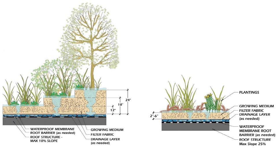
Table 5.5.2.1 Green Roof System Comparison (Source: Adapted from Archtoolbox.com)
Plant Options
moss, grass
moss, grass, herbs, flowers, shrubs
moss, grass, herbs, flowers, large shrubs, trees
5.5.2.2 Examples of Intensive and Extensive Green Roofs
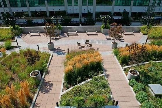
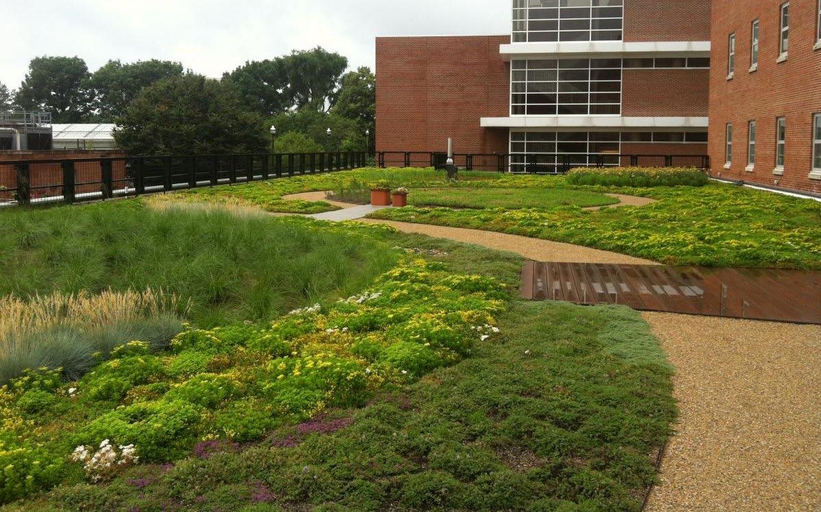
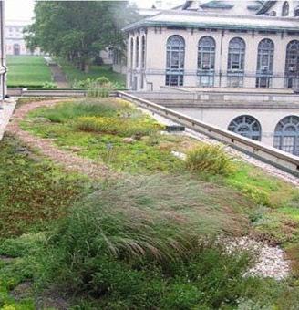

Green roof designs include waterproofing, support for the increased structural loads of fully saturated soil, plant media, and plants. They are designed so that water drains vertically through the media and then horizontally along a waterproofing layer towards the outlet, without water ponding on the roof They are constructed either “from scratch”
Figure
(Top left: intensive green roof at the Louisa apartments in Portland OR (Source:GBD Architects); Right: Semi-intensive green roof at CarnegieMellon University (Source:Green Roof Technology); Lower left: Extensive green roof on Howlett Hall at The Ohio State University (Source: Chadwick Arboretum & Learning Gardens)
by building up the roof layers, or using pre-made tray systems that create a seamless appearance but with less difficulty in construction. Figure 5.5.2.3 shows an example of a tray system and Figure 5.5.2.4 shows a layered system in use.
Figure 5.5.2.3 Examples of Modular (Tray) Green Roof System (Source: Greenrise Technologies, Murfreesboro TN)
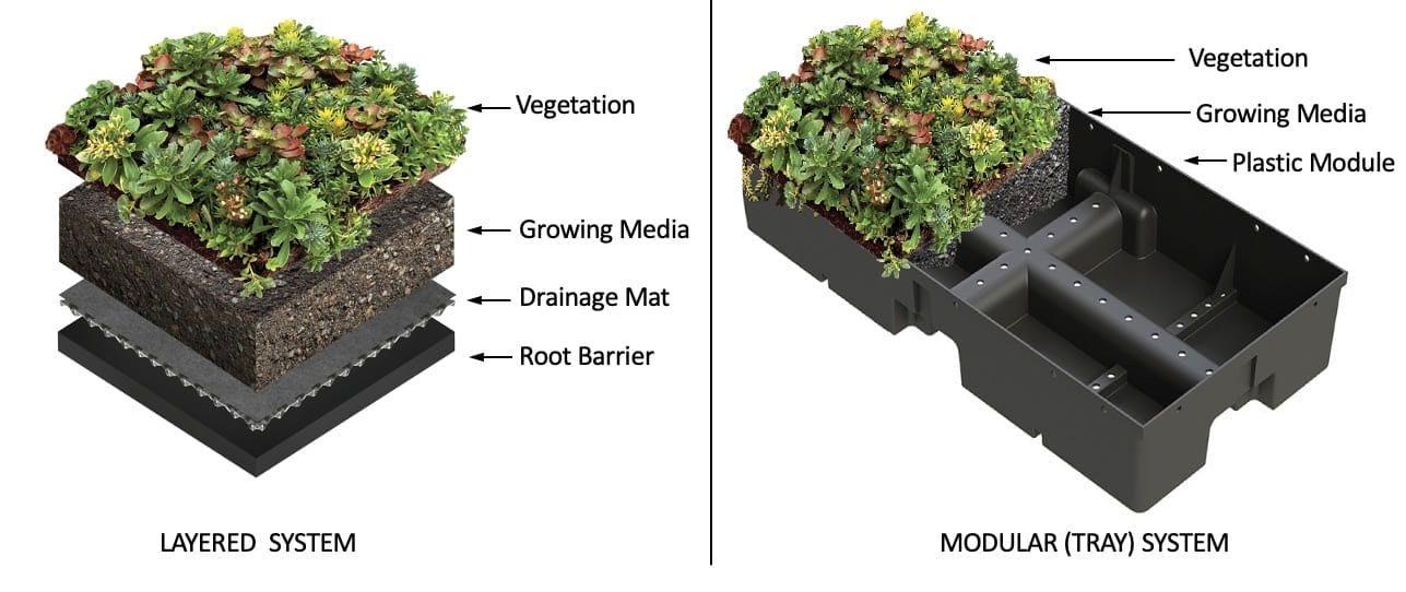
5.5.2.4 Green
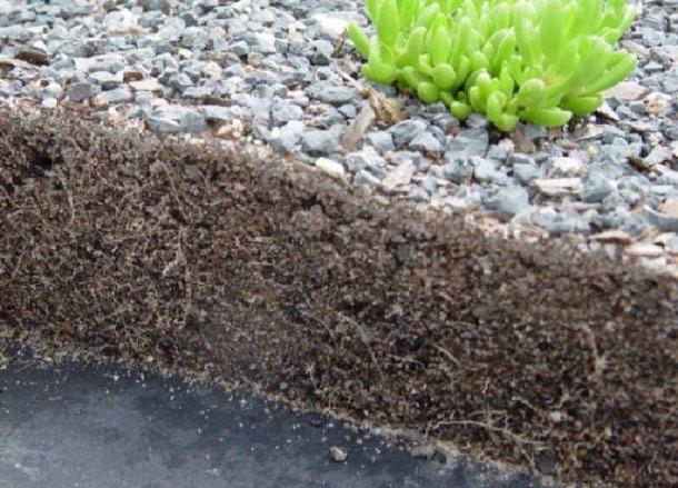
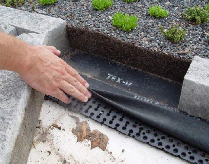
5.5.3 SCM Suitability
Use Table 5.5.3.1 to determine if a green roof is suitable for the application being considered.
Table 5.5.3.1 Green Roof Basin Suitability Factors
Factor
Suitability
Stormwater Quality Treatment Green roofs designed in keeping with the specifications established herein will satisfy local government stormwater quality treatment standards.
Channel Protection Channel protection volume (CPv) storage is not provided by a green roof.
Detention Stormwater detention is not provided by a green roof.
Figure
Roof System (Source: B.Hunt, North Carolina State University)
Pollutant Treatment
Capability
Treatment of Waste and Other Pollutants
Green roofs can be used to address the following common stormwater pollutants1:
Suitability by Land Use
1 Georgia Stormwater Management Manual, Volume 2 Technical Handbook, 2016 Edition.
*Cadmium, copper, lead, and zinc
Green roofs shall not be used to treat the following pollutants:
Construction sediment/waste
Landscape storage or waste
Sewage, pet, and livestock waste
Medical waste
Household & commercial wastes
Hazardous wastes
Gasoline, motor oils, greases, and other petroleum-based products
Fats, oils & grease (from food preparation)
Pesticides, fertilizers, herbicides
Other byproducts and waste materials expected, based on the property’s land use
General suitability criteria by land-use type are as follows.
*These policies do not preclude the use of green roofs on individually owned single family or multi-family residential lots. However, green roofs placed on residential lots will not be considered by the local government as suitable for compliance with local government stormwater management requirements due to the inherent difficulties in oversight and enforcement of long-term protection and maintenance requirements on residential lots
5.5.4 Limitations of This Design Specification
The criteria provided in the remainder of this design specification are not comprehensive to fully design of an operational green roof. Rather, they are intended as “guardrails” for green roofs that are proposed as SCMs to meet local government stormwater quality control requirements (the WQv standard) and adhere to local building codes and/or ASTM International Green Roof Standards. Additional design objectives, such as such as energy efficiency, green building or Leadership in Energy and Environmental Design (LEED) points, architectural considerations, visual amenities, and landscaping features, are beyond the scope of this specification. Regardless, beyond the standards provided by these criteria, design professionals must work with a commercial green roof manufacturer/installer to ensure proper design of functional green roofs. Additionally, consult references from Weiler and Scholz-Barth (2009), Snodgrass and Snodgrass (2006) and Dunnett and Kingsbury (2004) for more information on green roof design.
5.5.5
Design Requirements
Table 5.5.5.1 provides a limited set of standards and guidance for green roof design to meet the stormwater quality requirements of the local government
Table 5.5.5.1 Design Specifications for a Green Roof
The water quality rainfall depth (P) for determination of WQv: P = 1.0 inch. Since green roofs manage only the rainfall that falls on them, the contributing drainage area (A) for determination of WQv is the area of the green roof. Note: roof access paths, mechanical equipment, photovoltaic panels, and skylights are counted as part of the green roof for calculation purposes. These areas shall not exceed 20% of the roof area counted as green roof.
Design Element
Specification(s)
Acceptable methods to determine WQv are presented in Chapter 3 (Standards, Methods, and SCM Selection).
Location
Pretreatment
There are no location constraints for green roofs. However, green roofs proposed for residential land uses will be approved for compliance with the WQv standard only when placed on buildings owned in common (single and multi-family residential) or owned by the commercial property owner (multi-family residential only).
Pretreatment is not required on a green roof.
Drawdown Time Provide full treatment of the WQv within 72 hours of the rainfall event.
Building Codes
The green roof shall comply with all relevant local government building codes.
Consult a commercial designer/installer proficient in green roof design and construction for design specifications for the following green roof components Must comply with local building codes. In the event building codes do not address green roofs, must comply with the ASTM International Green Roof Standards
Roof deck
Structural components and capacity
Waterproofing layer
Insulation layer
Root barrier
5.5.6 Vegetation Design Requirements
Drainage layer, system, and outlet structures
Filter fabric
Growing media
Vegetation
Safety features
The importance of plants to a green roof’s function means they, like any SCM component, have design, installation, and maintenance specifications. Much of the design and maintenance of a green roof centers on plant coverage, health, and replacement. Table 5.5.6.1 provides the vegetation specifications for green roofs
Table 5.5.6.1 Vegetation Design Specifications
Vegetation
Minimum Coverage
Plant Survival
Plant Selection
Specification(s)
Green roofs shall have a vegetation coverage requirement of 100% of the green roof area, not including roof access paths, mechanical equipment, photovoltaic panels, and skylights.
The minimum coverage requirement must be achieved upon roof installation and then maintained thereafter.
Plant replacement is required when the minimum coverage goal of 100% is not achieved.
It is advisable for construction contracts to contain a replacement warranty that covers at least three grown seasons to help ensure adequate growth and survival of the vegetation planted on a green roof.
The general goal for vegetated roof systems designed for stormwater management is to establish a full and vigorous cover of low-maintenance vegetation that is self-sustaining and requires minimal mowing, trimming, or weeding. Green roof manufacturers/installers will have plant templates and resources to guide design professionals in achieving the desired vegetation design and aesthetic. See also ASTM E2400-06, Guide for Selection, Installation, and Maintenance of Plants for Green (Vegetated) Roof Systems.
The species and layout of the vegetation should reflect the location of the building, in terms of its height, exposure to wind, snow loading, heat stress, orientation to the sun, and shading by surrounding buildings. In addition, plants shall be selected that are fire resistant and able to withstand heat, cold, and high winds.
Compliance with the vegetation standards set forth in Table 5.5.6.1 shall be shown in a vegetation plan that is included with the water quality management plan (WQMP). Plan preparation requirements are below.
The plan must be prepared by a professional qualified in green roof design by their education or experience.
The plan shall include one or more labeled plans/details (to scale) showing the plants to be installed, their numbers, and locations. Plan notes showing a plant schedule and installation instructions are encouraged. This additional information allows both the plant installer at the time of construction, as well as the person(s) responsible for maintenance of the SCM after construction, to understand the original vegetation design and its compliance with the minimum standards.
5.5.7 Protection Design Guidance
SCMs designed for stormwater quality purposes must be maintained in keeping with the approved SCM design for the life of the land development 1 Design professionals can assist property owners with this requirement by including protective features in and around SCMs to limit the potential for damage by external factors. Often, the landscape and impervious features around an SCM can be tailored to its specific needs, and therefore used to protect its critical components.
For green roofs, protection is especially important for the planting area, the underlying layered components, and the roof drains and outlet(s). In general, walkways allow access for plant/roof maintenance. For semi-intensive and intensive green roofs, additional protective measures may be warranted depending on the intended use and design of the roof. Figure 5.5.7.1 shows an example of protective measures (i.e., sidewalk, bench, curbing) on an intensive green roof used as an amenity. Protection methods that work well are listed in Table 5.5.7.1.
Natural fencing such as vegetation borders/screens
Walkways and pedestrian benches
Geometry to allow maintenance without entering the planting area
Decorative fencing
Hardscaping
Educational or directive (e.g., no pets) signs
Trash cans
*The list presented in the table is not exhaustive. There may be other possible protection measures.
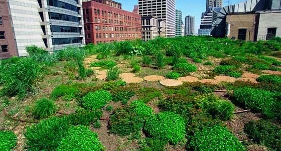


Table 5.5.7.1 Green Roof Protection Measures*
Figure 5.5.7.1 Examples of Protective Landscaping
Left: Stepping stones on a green roof in Chicago (Source: US National Park Service); Right: Pedestrian walkways, benches, and curbing on a green roof in Toronto, Canada (Source: City of Toronto ON, Canada)
5.5.8
SCM Maintenance on an Active Construction Site
SCM maintenance is regulated by local government ordinances from the moment they are installed. As well, SCMs must pass a final inspection prior to construction termination. This inspection will be performed to ensure they are constructed in accordance with the approved WQMP, and undamaged Thus, SCM maintenance is good practice to ensure construction termination goes smoothly. Relevant policies are as follows:
The property owner is responsible for SCM maintenance. If the property is still an active construction site, these responsibilities may fall to the land disturbance permittee until the project receives final approval from the local government and/or a Certificate of Occupancy.
Property owners may have others, such as a site contractor or landscaping company, maintain the green roof on their behalf. However, the local government will hold the property owner responsible for ensuring it is maintained in proper operating condition (i.e., as designed and constructed) regardless of who performs maintenance.
Maintenance activities, which include ensuring proper operation of the SCM as designed and required SCM inspections, must begin immediately following installation of the green roof.
Table 5.5.8.1 Maintenance Activities for Newly Installed Green Roofs
Maintenance activities shall be performed in keeping with the Northeast Tennessee SCM Inspection and Maintenance Manual Additional guidance on maintenance of newly installed green roofs located on active construction sites is provided in Table 5.5.8.1 Area or Component
Contributing Drainage Area
Keep the contributing drainage area clean. Sweep trash, debris, and sediment frequently so that it does not wash into the planting area during a rain event
Ensure SCM plants are watered and growing as expected
Remove and replace diseased, dying, or dead plants as soon as they are noticed.
Ensure the planting area remains free of sediment and wastes.
Ensure equipment, and people are not allowed in the planting area. Evidence of unwanted entry may look like tire tracks or footprints; mulch or stone displacement, or damage to components or vegetation; immediately determine and eliminate the cause and repair the area. Consider installing protection measures
Green Roof
Education
Visually observe the SCM’s function after rain events; there should be no standing water within 48 to 72 hours after a storm event, depending on the frequency of rainfall. If long-standing water is observed:
Inspect green roof components looking for standing water indicative of a blockage or damage; make repairs if needed.
If outlet blockages and damage can be ruled out, then the engineered soil mix may be clogged. This repair requires soil removal and reinstallation of the main treatment area; consult the design engineer.
Alert onsite subcontractors to the SCM and the following requirements:
No stockpiling of material on the planting surface and no exposed stockpiles in the planting bed’s drainage area.
Remove sediment, trash, debris, and empty trash cans frequently.
Green roof component protection
Advise landscaping subcontractors on proper protection and maintenance of the green roof, especially the following:
No heavy equipment (hand tools only).
No dumping of lawn clippings or landscape debris.
Area or Component
Post-Installation Maintenance Requirement
Plant maintenance needs/requirements (see above).
Green roof component protection
5.5.9 References
American Horticultural Society (AHS). 2003. United States Department of Agriculture Plant Hardiness Zone Map. Alexandria, VA.
ARC. Georgia Stormwater Management Manual Volume 2 Technical Handbook, 2016 Edition. Atlanta Regional Commission, 2016
ASTM International. 2019. Standard Test Method for Maximum Media Density for Dead Load Analysis of Green (Vegetated) Roof Systems. Standard E2399-05. ASTM, International. West Conshohocken, PA. available online: https://www.astm.org/e2399_e2399m-19.html
ASTM International. 2019. Standard Test Method for Saturated Water Permeability of Granular Drainage Media [FallingHead Method] for Green (Vegetated) Roof Systems. Standard E2396- 05. ASTM, International. West Conshohocken, PA. available online: https://www.astm.org/e2396_e2396m-19.html
ASTM International. 2019. Standard Test Method for Water Capture and Media Retention of Geocomposite Drain Layers for Green (Vegetated) Roof Systems. Standard E2398-05. ASTM, International. West Conshohocken, PA. available online: https://www.astm.org/e2398_e2398m-19.html
ASTM International. 2019. Standard Practice for Determination of Dead Loads and Live Loads Associated with Green (Vegetated) Roof Systems. Standard E2397-05. ASTM, International. West Conshohocken, PA. available online: https://www.astm.org/e2397_e2397m-19.html
ASTM International. 2019. Standard Guide for Selection, Installation, and Maintenance of Plants for Green (Vegetated) Roof Systems. Standard E2400-06. ASTM, International. West Conshohocken, PA. available online: https://www.astm.org/e2400_e2400m-19.html
Berhage, R., A. Jarrett, D. Beattie and others. 2007. Quantifying evaporation and transpiration water losses from green roofs and green roof media capacity for neutralizing acid rain. Final Report. National Decentralized Water Resource Capacity Development Project Research Project. Pennsylvania State University.
City of Portland OR. 2004. Stormwater Management Manual.
Clark, S., B. Long, C. Siu, J. Spicher and K. Steele. 2008. “Early-life runoff quality: green versus traditional roofs.” Low Impact Development 2008. Seattle, WA. American Society of Civil Engineers.
Dunnett, N. and N. Kingsbury. 2004. Planting Green Roofs and Living Walls. Timber Press. Portland, Oregon.
Maryland Department of Environment. (MDE). 2008. Chapter 5. Environmental Site Design. “Green Roofs.” Baltimore, MD. Miller, C. 2008. Green roofs as stormwater best management practices: Preliminary computation of runoff coefficients: sample analysis in the Mid-Atlantic states. Roofscapes, Inc. Philadelphia, PA.
MWS. 2012. Metropolitan Nashville-Davidson County Stormwater Management Manual Volume 5 Low Impact Development. Metro Water Services. Nashville, TN.
North Carolina State University (NCSU). 2008. Green Roof Research Web Page. Department of Biological and Agricultural Engineering. https://content.ces.ncsu.edu/plant-selection-for-extensive-green-roofs-in-the-research-trianglearea-of-north-carolina
Northern Virginia Regional Commission (NVRC). 2007. Low Impact Development Manual. “Vegetated Roofs.” Fairfax, VA. Philadelphia Water Department. July 2023. Stormwater Management Guidance Manual. Version 3.3
Schueler et al 2007. Urban Stormwater Retrofit Practices. Manual 3 in the Urban Subwatershed Restoration Manual Series. Center for Watershed Protection. Ellicott City, MD.
Snodgrass, E. and L. Snodgrass. 2006. Green Roof Plants: a resource and planting guide. Timber Press. Portland, OR.
UrbanStrong Green Building Specialists. 2023. www.urbanstrong.com
Van Woert, N., D. Rowe, A. Andersen, C. Rugh, T. Fernandez and L. Xiao. 2005. “Green roof stormwater retention: effects of roof surface, slope, and media depth.” Journal of Environmental Quality. 34: 1036-1044.
VADCR. 2011. Stormwater Design Specification No. 5: Vegetated Roof, Version 2.3, March 1, 2011. Virginia Department of Conservation and Recreation. https://swbmpvwrrc.wp.prod.es.cloud.vt.edu/wp-content/uploads/2017/11/BMPSpec-No-5_VEGETATED-ROOF_v2-3_03012011.pdf
Weiler, S. and K. Scholz-Barth 2009. Green Roof Systems: A Guide to the Planning, Design, and Construction of Landscapes over Structure. Wiley Press. New York, NY.
design
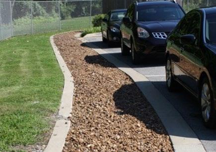
Overview
Infiltration basins are structural stormwater control measures (SCMs) that are shallow, landscaped areas filled with stone aggregate and sand filter layers for settling and infiltration of stormwater. Surface treatments can vary and include rock, grass, plants, and shrubs. Infiltration practices will have limited application in northeast Tennessee due to our region’s hilly terrain and high potential for karst features. (Photo courtesy of Nasville.gov)
ADVANTAGES/BENEFITS
Considered a green infrastructure (GI) SCM
Reduces post-construction stormwater volumes
Infiltration provides groundwater recharge
Good for small sites with porous soils
Can be designed to be an aesthetically pleasing landscaped area
DISADVANTAGES/LIMITATIONS
Limited applications due to lack of underdrain system
High clogging potential; shall not be used on sites with fine soils (clays or silts) in contributing drainage area
Highly sensitive to poor construction erosion and sediment control practices; cannot be used as a sediment trap/basin during construction
SCM operation is allowed only after the SCM’s drainage area is fully and permanently stabilized
May require a Class V Injection Well Permit
DESIGN CONSIDERATIONS FOR LOCATION, SIZING, & COMPONENTS
Completely drain within 48 hours after a rainfall event
No more than 6% slope (for pre-construction SCM footprint)
Stormwater pretreatment and energy dissipation are required at all inlets
DESIGN CONSIDERATIONS FOR LONG-TERM PROTECTION
Primary concern is soil compaction
Protect from entry by vehicles and heavy equipment
Suitable for a wide variety of protective designs (woody or prickly shrub borders, rocks/cobbles, decorative fencing, signage, etc.).
DESIGN CONSIDERATIONS LONG-TERM MAINTENANCE
Primary routine maintenance activities will be inlet and pretreatment device cleaning, and plant care (if vegetated)
Consider permanent signs to dissuade use as a pet relief area if SCM is near a pedestrian area
Provide trash cans and pet waste stations in the drainage area
5.6.1 General Description
Infiltration basins are shallow, landscaped excavations filled with an engineered soil mix and stone to create an underground reservoir for stormwater The water quality volume (WQv) gradually exfiltrates through the bottom and sides of the basin into the subsoil (see Figure 5.6.1.1). By diverting stormwater into the soil, an infiltration basin not only manages stormwater but also helps to preserve the natural water balance on a property. Infiltrated stormwater can recharge groundwater and preserve base flow. Vegetative cover (i.e., grass) is not required for an infiltration basin, but there must be some type of uncompacted, pervious ground cover such as decorative landscape stone to allow water to infiltrate into the rock-filled excavation; however, if grass is used to cover the basin, transpiration provides an additional stormwater/pollutant reduction mechanism.
5.6.2 Design Applications
Northeast Tennessee’s characteristic hilly terrain, combined with generally low native soil permeability and high potential for karst features (e.g., sinkholes) are all factors that limit the application of infiltration basins. The latter characteristic is of particular interest since infiltration basins do not include underdrain systems that discharge the WQv to an outlet. Thus, care must be taken in their selection to ensure the proposed development is suitable for their use. This will include confirmation that the proposed location of the infiltration basin (and a substantial area around it) are not underlain by or adjacent to soluble, carbonate bedrock, which is a primary indicator of karst hydrology.
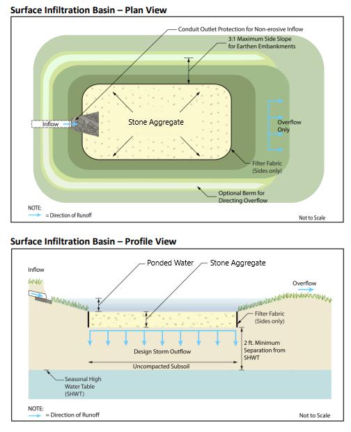
Another key factor in the selection of an infiltration basin for stormwater treatment is the pollutant expected after construction is finished. Infiltration basins are not intended to trap high sediment loads due to the potential for clogging of the storage stone. Therefore, they are best suited for drainage areas comprised of fully impervious surfaces only, in developments where future sediment loads are assured to be relatively low. An example of such a drainage area is a rooftop, courtyard, or parking area in an established office park that has little to no potential for further development
Typical locations for infiltration basins include:
Parking lot islands. Infiltration basins can be sited as trench features between parking space rows or within parking lot islands (see the left photo in Figure 5.6.2.1) Flow into the trench is achieved with sheet flow over flush pavement edges
Figure 5.6.1.1 Infiltration Basin Plan and Profile View
Adapted from the New Jersey Stormwater BMP Manual
(with the SCM) or through curb cuts if curbing around these areas is required by local government parking lot design requirements. Curb cuts are more prone to blockage, clogging, and erosion and thus have a minimum opening width of 18 inches. For flush pavement edges between rows of parking stalls, curb blocks are highly recommended to prevent inadvertent vehicle entry into the SCM. An apron of dense turf or cobbles around the edge of the area functions as a filter strip to provide pretreatment.
Parking lot edge. Small parking lots can be graded so that flows reach a flush pavement edge or curb cut and enter an infiltration basin (see the infiltration trench in the right photo in Figure 5.6.1.2). The turf at the edge of the parking lot functions as a filter strip to provide pre-treatment for the infiltration basin. The depression for the basin is located in the pervious area adjacent to the parking lot. Stormwater volumes greater than the WQv will discharge into the infiltration basin overflow shown at the far end of the trench.
Courtyards. Stormwater collected in a storm drain system or roof leaders can be directed to courtyards or other pervious areas on site where infiltration basins can be installed.
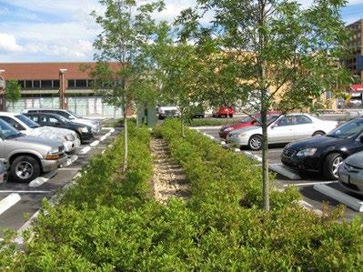
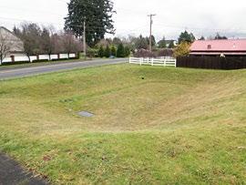
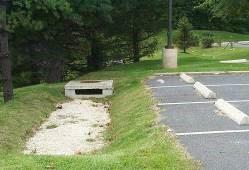
5.6.3 SCM Suitability
Use Table 5.6.3.1 to determine if an infiltration basin is suitable for the application being considered.
Table 5.6.3.1 Infiltration Basin Suitability Factors
Factor
Stormwater Quality Treatment
Suitability
Infiltration basins designed in keeping with the specifications established herein will satisfy local government stormwater quality treatment standards.
Channel Protection It may be possible to size an infiltration basin to infiltrate the channel protection volume for smaller sites.
Detention
Infiltration basins are generally not suitable for peak discharge (detention) control, even for small design storms (the 2-year event). The basin must be designed to bypass these flows. However, infiltration basins can be helpful in addressing small, limited, onsite drainage issues when designed with additional storage capacity for volumes higher than the WQv. Pollutant Treatment Capability
Infiltration basins can be used to address the following common stormwater pollutants1:
1 Georgia Stormwater Management Manual, Volume 2 Technical Handbook, 2016 Edition.
Figure 5.6.2.1 Examples of Infiltration basins
Left: Hill Center-Belle Meade, City of Nashville, TN; Middle: location unknown, Stormwater Partners of SW Washington; Right: location and source unknown
Factor
Treatment of Waste and Other Pollutants
*Cadmium, copper, lead, and zinc
Infiltration basins shall not be used to treat the following pollutants:
Construction sediment/waste
Landscape storage or waste
Sewage, pet, and livestock waste
Medical waste
Household & commercial wastes
Hazardous wastes
Gasoline, motor oils, greases, and other petroleum-based products
Fats, oils & grease (from food preparation)
Pesticides, fertilizers, herbicides
Other byproducts and waste materials expected, based on the property’s land use
Privately owned infiltration basins are not allowed in the public right-of-way.
General suitability criteria by land-use type are as follows. See Chapter 3 (Standards, Methods, and SCM Selection) for more information.
Suitability by Land Use
5.6.4 SCM Location Requirements
Location constraints for infiltration basins are provided in Table 5.6.4.1.
Table 5.6.4.1 Infiltration Basin Location Requirements
*These policies do not preclude the use of infiltration basins on individually owned single family or multi-family residential lots. However, basins placed on residential lots will not be considered by the local government as suitable for compliance with local government stormwater management requirements due to the inherent difficulties in oversight and enforcement of long-term protection and maintenance requirements on residential lots Physical Element
Minimum setbacks, measured from the edge of the infiltration basins, are as follows:
10 feet from a property line.
100 feet from building foundations
Minimum SCM Setbacks
Flow Avoidance
Recommended Land Use
Siting
100 feet from underground septic systems.
1200 feet from private and public water supply wells.
200 feet from public water supply reservoirs (measured from the edge of the water).
At least 5 feet down gradient from underground utility lines.
Infiltration basins shall not be located where it will receive continuous or dry weather inflows from springs, seeps, sump pumps, wash stations, or other sources.
Infiltration basins are best suited for drainage areas comprised of fully impervious surfaces only, in developments where future sediment loads are assured to be relatively low.
On properties with multiple SCMs, infiltration basins shall always be located so they do not receive discharges from other SCMs (e.g., from detention basins designed for flood control, etc.).
To reduce the potential for costly maintenance and/or system reconstruction, it is strongly recommended that the basin be located in an open space, with the top of the structure as close to the ground surface as possible.
Physical Element Requirement
Infiltration basins shall not be located beneath paved surfaces, such as parking lots.
Utility Avoidance
Infiltration basins shall not be located above underground dry utility lines (electric, cable, and telephone) and water/wastewater infrastructure.
Design professionals must consult the local utility to determine the horizontal and vertical clearance required between SCMs and dry and wet utility lines.
5.6.5 Design Requirements
Figure 5.6.5.1 shows the basic components of an infiltration basin. The criteria provided in Table 5.6.5.1 shall be considered minimum standards and specifications for the design of infiltration basins
Figure 5.6.5.1 Infiltration Basin Basic Components
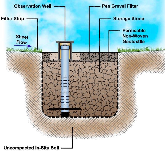
Table 5.6.5.1 Design Specifications for the Contributing Drainage Area
Design
Drainage Area
Specification(s)
Maximum contributing drainage area (CDA) = 5 acres; however, 2500 ft2 to 2.0 acres is preferred
Contributing drainage areas greater than 5 acres can be divided into multiple areas, each drainage area draining to a separate infiltration basin or another SCM.
Slope Maximum slope = 6%; however a nearly flat slope is preferred.
Design Element
Controls for Waste & Other Pollutants
Table
Specification(s)
Appropriate controls shall be included in the design of the contributing drainage area to the SCM to address any Wastes and Other Pollutants (see Table 5.6.3.1 above) that are expected on the property after construction. Use the proposed land use as a guide to determine appropriate controls. Examples of such controls include, but are not limited to, dumpsters, trash cans, covered materials/waste storage areas, covered materials transfer areas, oil and grease waste controls, and pet waste stations.
5.6.5.2 Design Specifications for the Infiltration Basin
Design Element
Specification(s)
Infiltration basins shall meet ALL the following conditions:
The SCM will be constructed in uncompacted, native soil that has an infiltration rate between 0.5 and 11 inches/hour, and these soil conditions can be maintained throughout construction of the land development.
Infiltration Feasibility Criteria
Sufficient protection measures to prevent soil compaction within and around the basin after construction are included in the design.
The development and the SCM meets all infiltration feasibility factors established in the Infiltration Feasibility Form provided in Appendix C (Infiltration Feasibility Form).
Infiltration tests are required for Group 1 SCMs before and after construction See Appendix F (Policies for Soil Infiltration Tests & Soil Borings) for infiltration test requirements. Additional geotechnical information may be required by the local government.
Class V Injection Well Permits
Although unlikely, infiltration basins may require a Class V Injection Well Permit from the Tennessee Department of Environment and Conservation (TDEC), pursuant to TDEC rule 0400-4506-.06, especially those that are designed to be deeper than its widest surface dimension. Consult TDEC for more information. Regardless, the requirement for a permit is determined by TDEC, not the local government. When a permit is required, a copy must be provided to the local government prior to, or with, the submission of the Water Quality Management Plan.
The water quality rainfall depth (P) for determination of WQv is 1.0 inch.
Acceptable methods to determine WQv are presented in Chapter 3 (Standards, Methods, and SCM Selection).
Water Quality
Volume (WQv)
If the infiltration basin can treat the entire WQv for its contributing drainage area, additional SCMs for stormwater quality treatment are not required in the contributing drainage area.
Infiltration basins are not appropriate for a treatment train since they do not discharge the WQv.
If an infiltration basin cannot treat the entire WQv calculated for its contributing drainage area, then an alternate or additional SCM must be selected to treat the entire WQv.
An offline configuration is the preferred design configuration for infiltration basins as they are located away from the main flow path for the drainage area, thus avoiding large flood flows.
A flow splitter, diversion structure, or other means is used upstream of the infiltration basin’s inlets to redirect the design volume (typically this will be the WQv) to the SCM while still allowing larger flows to remain in the main flow path.
Offline and Online Design Configuration
The structure shall be sized to pass the peak discharge of the design volume (typically this will be the water quality peak discharge, Qwq) to the infiltration basin The method to determine Qwq is provided in Chapter 3 (Standards, Methods, and SCM Selection)
An online configuration is designed and constructed so the main flow path for the drainage area passes through the infiltration basin This configuration can have a high potential for sediment deposition in the basin and a corresponding need for frequent remedial maintenance. Thus, an
Design Element
Specification(s)
online infiltration basin is permissible only for drainage areas that are 100% impervious and have low potential for sediment and debris loads, such as drainage from a small building rooftop Flow regulators (flow splitters, diversion structures, and overflow structures) shall be designed in keeping with Sections 5.16 (Inlets, Energy Dissipation, and Pretreatment Measures).
The entire infiltration basin must be accessible for maintenance without requiring the entry of vehicles or heavy equipment into the basin.
Maintenance Access and Easement
A maintenance easement to (and including) the infiltration basin must be provided from a public roadway. The easement must be free of permanently affixed obstructions (e.g., trees, pools, fences without gates, permanent signs, etc.) to allow maintenance vehicles and equipment to safely pass.
Stormwater shall enter the infiltration basin at non-erosive velocities (maximum of 5 ft/sec). Energy dissipation measures, such as vegetated buffer strips or rock or riprap areas, shall be provided.
Energy Dissipation & Pretreatment
Pretreatment, such as a dense grass filter strip, rock apron, or other means, shall be included immediately below inlet(s) to remove gross solids, trash, and sediment from stormwater prior to flowing into the main treatment area. Pretreatment options and design specifications are provided in Section 5.16 (Inlets, Energy Dissipation, and Pretreatment Measures).
In areas where litter, leaves, or other floatables are readily expected in stormwater to the infiltration basin, pretreatment shall additionally include a screen, grate, or other measure for debris capture prior to discharge into the infiltration basin.
The geometry of the infiltration basin shall be designed such that stormwater flowing into the infiltration basin is distributed evenly across its entire surface area, and to provide for construction and maintenance from the edge of the infiltration basin (to avoid entry by construction/maintenance workers). Geometry requirements are as follows:
Maximum basin width = 25 feet.
Geometry
Minimum basin depth = 3 feet, unless a shallow water table necessitates less.
Maximum basin depth = 8 feet; a depth between 3 to 5 feet is preferred.
Broader, shallower infiltration basins perform more effectively than narrower, deeper basins because stormwater is distributed over a larger surface area. As well, a basin depth less than the widest surface dimension will allow the owner to avoid a requirement by TDEC for a Class V Injection Well Permit.
Inlets and Pretreatment
Basin Bottom
Ponding Depth
Minimum Depth to Water Table
Minimum Hydraulic Head
Stormwater pretreatment must be provided at all inlets such that 100% of inflows to the base are pretreated. These measures may also be used for energy dissipation Typically, pretreatment is provided by a grass filter strip or pea gravel diaphragm at the inlet(s). However, grass channels, sediment forebays, check dams, splash blocks, level spreaders and other types of measures are also suitable and can prevent scour in the basin.
The bottom of the basin shall be flat across its length and width to evenly distribute infiltration, encourage uniform infiltration through the bottom, and reduce the risk of clogging.
Maximum surface ponding depth = 12 inches; although 9 inches is recommended.
Minimum separation distance (bottom of excavation to seasonally high-water table) = 2 feet.
Soil borings shall be used to determine the seasonally high-water table. See Appendix F (Policies for Soil Infiltration Tests & Soil Borings) for soil boring requirements.
Minimum hydraulic head = 3 feet
The hydraulic head is the difference in the inflow elevation, including the design ponding depth, to the outflow elevation at the bottom of basin.
Design Element
Drawdown Time
Overflow Structure
Specification(s)
The WQv shall exfiltrate the basin to at least 2 feet below the bottom within 72 hours.
An overflow structure that safely passes stormwater that exceeds the design volume of the infiltration basin (typically this will be the WQv) must be included in the design to prevent flooding the basin and adjacent areas.
Use one or more overflow inlets set slightly above the maximum water ponding elevation (or no more than 12 inches above the mulch layer if the basin is vegetated) to allow drainage of excess stormwater.
Overflow inlets can be a yard drain catch basin with a suitable debris/trash rack, though any number of conventional systems could be used. The right picture in Figure 5.6.1.2 (several pages above) shows a concrete overflow structure for the infiltration basin that serves a parking lot.
The overflow structure shall discharge to the onsite stormwater conveyance system or detention basin. Discharges must be non-erosive (maximum velocity of 5 ft/sec).
See additional design information in Section 5.17 (Overflow Controls).
The remaining rows specify the subsurface layers of the SCM, starting at the bottom.
Limit the excavation to the width and depth specified in the design.
In-situ Soil
Observation Well
Scarify the bottom of the excavation to a minimum depth of 6 inches by raking, disking, or tilling prior to placement of SCM layers. The sidewalls shall be uniform with no voids and scarified prior to backfilling.
Trim all large roots on the sides and bottom of the excavation before layers are placed. Place layers in a way that does not cause compaction of the underlying in-situ soil.
An observation well is required for all visual inspection of the stone aggregate reservoir. The well shall:
be installed along the centerline of the infiltration basin;
extend from an elevation at least 6 inches above design ponding depth to bottom of the basin;
be comprised of a 4 to 6 inch diameter perforated PVC (AASHTO M 252) pipe and;
be capped and locked to prevent tampering and vandalism.
A choker layer shall be used to separate the underlying in-situ soil from the stone aggregate reservoir. Choker layer options are as follows:
Bottom Choker Layer
Geotextile
Stone Aggregate Reservoir
Surface Layer
A 2-to-4-inch layer of washed choker stone (ASTM D 448 size No. 8, 3/8” to 1/8” or ASTM D 448 size No. 89, 3/8” to 1/16”); or,
A 6-inch layer of clean, washed sand.
A non-woven geotextile fabric having a flow rate greater than 110 gal/min/ft2 shall be installed on the sides only of the excavation to maintain separation between the in-situ soil and stone aggregate.
The basin shall be filled with double-washed, bank-run gravel, 1.5 to 2.5 inches in diameter with a void space of about 40% (AASHTO No. 3 stone). Soil/sand shall not contaminate the stone.
A non-woven geotextile fabric having a flow rate greater than 110 gal/min/ft2 shall be installed on top of the stone aggregate to maintain separation between the stone aggregate and stone or topsoil surface layer.
The surface layer protects the stone aggregate reservoir and acts as a filter layer for the basin. This is so the surface layer can be easily removed and replaced when it becomes clogged, thus avoiding a larger repair below the surface layer.
The surface layer shall be one of the following options:
Design Element
Specification(s)
Clean pea gravel (ASTM D 448 size No. 8, 3/8” to 1/8”), sand, or rock cobbles, having a depth of 6 to 8 inches
Permeable topsoil, such as the engineered soil mix used in bioretention areas, and ground cover/grass in keeping with Section 5.6.7 (Surface Layer Design Requirements) below. The depth of the topsoil layer will be dictated by the grass selected but shall be no less than 6 to 8 inches.
5.6.6 Design Procedure
Table 5.6.6.1 provides the design procedure for an infiltration basin.
Table 5.6.6.1
Design Procedure
Step Design Activity
Evaluate infiltration basin feasibility.
Step 1
Use the feasibility criteria provided in Tables 5.6.5.1 and 5.6.5.2 to determine if an infiltration basin is feasible for the selected location on the land development site. Consider especially whether it is appropriate for the proposed development based on the intended land use of the property, the maintenance burden, and assumptions or knowledge of how the property owner(s) will care for the infiltration basin after construction (e.g., self-maintenance, property/facilities management maintenance, landscape contractor). If possible, include the property owner(s) in the SCM selection since they will be responsible for maintenance.
If an infiltration basin is determined to be feasible and appropriate for the proposed development, create a rough layout of its dimensions, taking into consideration existing trees, utility lines, and other obstructions to ascertain if it will fit into the desired space, given its general design requirements.
Complete the Infiltration Feasibility Form provided in Appendix C (Infiltration Feasibility Form) to be sure that all feasibility criteria are addressed.
Determine the goals and primary function of the infiltration basin.
Consider whether the intention is to:
Step 2
Comply with the local government stormwater quality requirements (i.e., treat the WQv, provide channel protection, etc.).
Include additional storage capacity for a higher level of stormwater quality treatment or to address a small onsite drainage issue.
Enhance landscape and provide aesthetic qualities.
Calculate the design storage volume (DSv) for the contributing drainage area
Step 3
Typically, the DSv = WQv, unless the infiltration basin cannot manage the entire WQv or will be used to control a volume larger than the WQv.
Use one of the calculation methods explained in Chapter 3 (Standards, Methods, and SCM Selection) to calculate WQv.
Step 4
Determine the minimum surface area of the infiltration basin. ������������ = ������������ × ������������ ���� × (������������ + ������������ ) × ������������������������ where:
Ain = surface area at the maximum ponding elevation (ft2)
DSv = design storage volume (typically this will be the WQv) (ft3)
Din = planting media depth (ft)
Step Design Activity
k = coefficient of permeability of the surface layer (ft/day) (use 0.5 ft/day for topsoil/engineered soil media filter layers; use 300 ft/day for pea gravel or sand filter layer)
Hin = average height of water ponding above infiltration basin bed (ft) (use 50% of the maximum ponding elevation)
Tib = drawdown time (days) (can range between 1 to 3 days)
Step 5
Determine other parameters needed to size of diversion structures (if any) and overflow structures. Use the standard NRCS methods and the water quality calculation methods explained in Chapter 3 (Standards, Methods, and SCM Selection) to compute the curve number (CN), time of concentration (Tc), and the water quality peak discharge (Qwq).
Use Sections 5.16 (Inlets, Energy Dissipation, and Pretreatment Measures) and 5.17 (Overflow Controls) for structure guidance and requirements.
Step 6 Design the inlets, pretreatment measures, and energy dissipation measures.
Step 7
See Section 5.16 (Inlets, Energy Dissipation, and Pretreatment Measures) for requirements.
Design the surface layer and protection measures.
Vegetation, if used, shall be in accordance with the vegetation design requirements provided in Table 5.6.7.1 Use guidance found in Section 5.6.8 (below) to design protection measures.
5.6.7 Surface Layer Design Requirements
Table 5.6.7.1 provides the vegetation specifications for a grassed infiltration basin.
Table 5.6.7.1 Vegetation Design Specification
Vegetation Design Element
Minimum Coverage
Plant Survival
Plant Selection
Specification(s)
If the infiltration basin is designed to be vegetated, the entire (100%) surface area of the infiltration basin, not including inlets, outlets, overflow and diversion structures, and observation wells, must be covered by dense, healthy grass (turf, native, or ornamental grass/groundcover) or a washed stone or sand. Other types of vegetation (e.g., woody plants such as shrubs and trees) and non-vegetated ground cover (e.g., mulch, crumb rubber) are prohibited. This requirement also applies to any vegetated filter strips used for pretreatment and energy dissipation.
Areas of bare soil are not allowed on the basin surface, or in the land surrounding the basin’s main treatment area.
Sod or appropriate permanent seeding shall be applied as soon as the basin is installed to achieve 100% coverage of the surface area within 2 to four 4 weeks. If seeding is used, the basin shall not receive stormwater discharges until it is fully and densely grassed. This will prevent erosion on the surface of the basin.
Grass replacement is required when the minimum coverage goal of 100% is not achieved. The use of sod is preferred over seeding due to its ability to significantly reduce the potential for soil erosion within the basin’s main treatment area.
landscape expert, such as a landscape architect, local nursery, or Master Gardener from the Tennessee Extension Master Gardener program. (https://mastergardener.tennessee.edu/)
Native plant species better suited to local hydrologic conditions are recommended.
Vegetation Design Element
Specification(s)
Grass selected for the infiltration basin must be tolerant to cycles of drought and inundation, as these conditions are expected. For guidance on appropriate grass species, consult a plant and Plants suitable for the United States Department of Agriculture (USDA) Plant Hardiness Zone 6a7a are recommended depending on your zip code.
Consider future maintenance needs when selecting grass for the basin. The level of plant care needed to maintain the landscape should influence grass selection.
Compliance with the vegetation standards set forth in Table 5.6.7.1 shall be shown in a vegetation plan that is included with the water quality management plan (WQMP). Plan preparation requirements are below.
The plan must be prepared by a professional qualified in landscape design by their education or experience.
The plan shall include one or more labeled plans/details (to scale) showing the plants to be installed, their numbers, and locations. Plan notes showing a plant schedule and installation instructions are encouraged. This additional information allows both the plant installer at the time of construction, as well as the person(s) responsible for maintenance of the SCM after construction, to understand the original vegetation design and its compliance with the minimum standards.
Landscaped SCMs may not be recognized under the local government’s codes as property landscaping. Therefore, additional requirements for property landscaping may apply.
5.6.8 Protection Design Guidance
SCMs designed for stormwater quality purposes must be maintained in keeping with the approved SCM design for the life of the land development. Design professionals can assist property owners with this requirement by including protective features in and around SCMs to limit the potential for damage by external factors. Often, the landscape and impervious features around an SCM can be tailored to its specific needs, and therefore used to protect its critical components.
For infiltration basins, protection is especially important for the main treatment area. Encroachments by vehicles, heavy equipment, and pedestrians can kill the grass (if the basin is vegetated), compact the engineered soil, and damage interior components. However, infiltration basins are especially well-suited to a variety of protection methods that can enhance the property’s landscape aesthetic or impervious surface function. Protection methods that work well with infiltration basins are listed in Table 5.6.8.1. Examples of infiltration basin protection measures are shown in Figure 5.6.8.1.
Table 5.6.8.1 Infiltration Basin Protection Measures*
Passive Protection Measures
Natural fencing such as vegetation borders/screens (e.g., tall grass such as variegated liriope)
Dense vegetation or clumping at the perimeter
Driveways, sidewalks, or walkways around the SCM
Pedestrian benches on the perimeter
Geometry/sizing to allow maintenance without vehicles/equipment entering the area
Active Protection Measures
Decorative fencing
Curbs or curb blocks
Hardscaping
Block edging or walls
Cobble/boulder edging
Educational or directive (e.g., no pets) signs
Pet waste stations
*The list presented in the table is not exhaustive. There may be other possible protection measures.
Figure 5.6.8.1 Examples of Infiltration Basin Protection
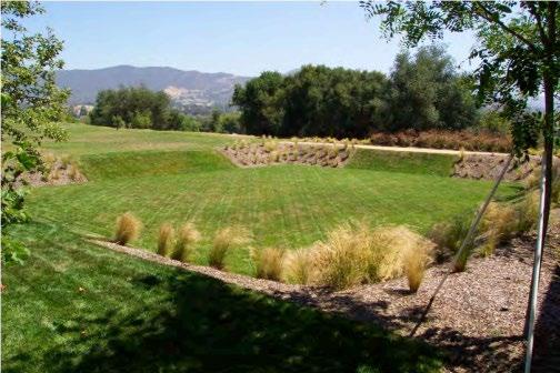
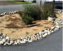
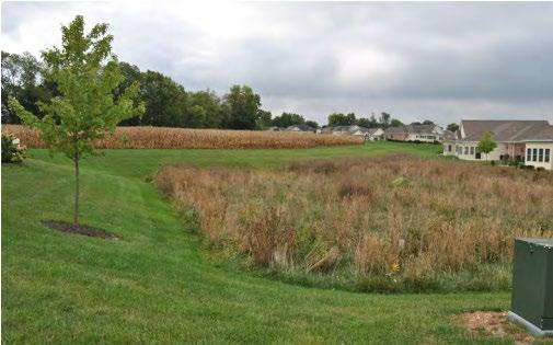
Top left: Steep side slopes and ornamental plant beds dissuade vehicle entry. However, remedial repairs are difficult to perform for a large surface area (Source: https://www.flickr.com/photos/scpr/4949432301); Top right: Tall native grasses dissuade entry into this basin (Source: Mount Joy Borough, PA); Left: Rock cobbles provide pretreatment, energy dissipation, and protection (Source: Mount Joy Borough, PA; Right: Rock cobbles protect the surface of this infiltration basin (Source: SuDS Wales).

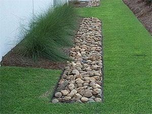
5.6.9 Site Preparation and Land Disturbance Requirements
The following information is provided to support proper and effective construction and protection of infiltration basins during land disturbance activities and site construction. Mandatory requirements are identified using “shall” or “must.” All other statements can be regarded as non-mandatory guidance. Site preparation and land disturbance basins described in this section shall be shown on the Erosion Prevention and Sediment Control (EPSC) plan for the proposed land development. Table 5.6.9.1 provides requirements for site preparation and land disturbance basins for land developments with infiltration basins.
Table
5.6.9.1 Site Preparation Basins
Policy
Preservation of the native, uncompacted soil during site construction and construction phasing and sequencing are critical to the success of an infiltration basin. Thus, the following requirements apply:
The location of the basin shall include a protection zone extending a minimum of 10 feet around the perimeter of the basin and shall be protected from encroachments by vehicles, equipment, and workers during site construction. To the extent practical, work within the perimeter should be confined only to that required for the installation of the infiltration basin.
The infiltration basin protection zone shall be identified and marked prior to commencement of land disturbance activities using highly visible orange fencing (or similar visible protective measures) and signage to advise construction personnel not to enter the area. Construction vehicle and equipment parking, thoroughfares, wash-off areas, and sediment traps/basins shall not be located in the infiltration basin protection zone.
Clearing, grubbing, and grading using heavy equipment is prohibited in the protection zone. When these activities are necessary for construction of the infiltration basin, hand tools or smaller equipment that can reach into the protection zone must be used to avoid compaction of the native soil within the zone.
Erosion prevention and sediment control (EPSC) measures must safeguard the protection zone both prior to, during, and if required, after its installation.
Site construction shall be sequenced such that the infiltration basin is installed only after the area draining to it has been fully and permanently stabilized.
5.6.10 Installation Requirements
The information in Table 5.6.10.1 provides a typical construction sequence to properly install infiltration basins. These steps may be modified to reflect different applications or site conditions. Installation basins shall be shown in the EPSC and WQMP plans, as appropriate for the proposed land development.
Table 5.6.10.1 Installation Steps
Step Requirement
The installation site shall be checked for existing utilities prior to construction.
Construction of the infiltration basin shall be performed only after the area draining to it has been fully stabilized to prevent sediment discharges. Where this requirement cannot be met, a temporary bypass shall be designed to prevent stormwater discharge to the infiltration basin until its drainage area is fully stable. It may be necessary to block certain curbs or other inlets while it is being constructed.
Step 1
Step 2
Supervision during construction is required to ensure the infiltration basin is constructed/installed in accordance with the approved EPSC and WQMP plans. The design professional or a designee under their supervision must inspect the infiltration basin at critical stages of construction. Examples of critical stages of construction include protection zone and ESPSC measure installation, excavation, and final inspection. This ensures that the contractor’s interpretation of the plan is consistent with the design professional’s intentions and allows the design professional to certify (in the as-built plan) that the infiltration basin is built in keeping with the permitted plan.
Construction sites can have many different contractors responsible for different portions of the site or aspects of construction. Therefore, subtle differences in site grading, drainage, and paving elevations from those identified in the design, or relative to different areas/aspects of construction, can affect the hydraulics of the proposed infiltration basin. The following activities should be done prior to construction to ensure the approved design is still valid:
During the preconstruction meeting, review and confirm that the actual boundaries of the infiltration basin’s contributing drainage area and inlet elevations conform with the approved design.
Any changes that result from the preconstruction meeting must be shown as a revision to the permitted plan and resubmitted to the local government for approval. This includes changes to material certifications for aggregate, engineered soil mix, and any geotextiles if not approved prior to the preconstruction meeting.
Install protection and EPSC measures as indicated in Table 5.6.9.1 above.
Step 3
Step 4
Step 5
Special protection measures, such as erosion control fabrics, may be necessary to protect vulnerable side slopes from erosion during the construction.
Pretreatment measures shall be excavated first and then sealed to trap sediments prior to excavation of the main basin.
Excavate the infiltration basin to its appropriate design depth and dimensions. Excavators or backhoes, if used, must be located on the sides of the infiltration basin, and have adequate reach inside the footprint for full excavation. DO NOT allow vehicles or heavy equipment in the protection zone
Step Requirement
For excavation of large infiltration basins, use a cell construction approach where the area is split into 500to 1,000-square foot temporary cells with a 10- to 15-foot earth bridge in between. This allows cell excavation from the sides.
Continue to avoid the use of heavy equipment and vehicles in the main treatment area (and protection zone) for the remainder of the steps listed below.
Step 6 Scarify (rip) the bottom soils to a depth of 6 to 12 inches to promote greater infiltration.
Step 7
Step 8
Step 9
Place the geotextile fabric in the basin (with a 6-inch overlap).
Place the bottom stone layer in the basin.
Apply the stone aggregate in 12-inch lifts until the desired surface elevation of the infiltration basin is achieved.
Wait a few days to check for settlement and add additional stone as needed to achieve the design elevation.
Install the surface layer
If the surface cover is grass, install grasses as shown in the vegetation plan (see Section 5.6.8 and Table 5.6.8.1). Install (or locate) temporary irrigation measures, if needed, to ensure plants will be watered during the remainder of site construction.
Step 10
Step 11
EPSC measures can be removed from the inlets once the infiltration basin’s side slopes have good vegetative stability, and the drainage area is fully and permanently stabilized. However, if the drainage area includes newly installed asphalt, the inlet blocks should remain in place for at least three storm events after asphalt installation. A substantial amount of fine particles and grit are discharged from newly installed asphalt during the first several storms that produce stormwater after installation. Maintenance will be required to remove the particles and grit if erosion/sediment control devices are removed too early.
Maintain the infiltration basin in keeping with Section 5.6.11 below.
Prepare the Record Drawing and submit it to the local government for review and approval with the engineer’s as-built certification before a final or temporary Certificate of Occupancy can be obtained. Advise the landowner (i.e., the person(s) taking ownership of the property immediately after its development) of the presence of the infiltration basin and provide them with a copy of the property’s Record Drawing. The plan must clearly show the location of the infiltration basin on the property and list the activities (and their frequencies) necessary for its proper maintenance.
5.6.11 SCM Maintenance on an Active Construction Site
SCM maintenance is regulated by local government ordinances from the moment they are installed. As well, SCMs must pass a final inspection prior to construction termination. This inspection will be performed to ensure they are constructed in accordance with the approved WQMP, undamaged, and free of sediment and debris. Thus, SCM maintenance is good practice to ensure construction termination goes smoothly. Relevant policies are as follows:
The property owner is responsible for SCM maintenance. If the property is still an active construction site, these responsibilities may fall to the land disturbance permittee until the project receives final approval from the local government and/or a Certificate of Occupancy.
Property owners may have others, such as a site contractor or landscaping company, maintain the infiltration basin on their behalf. However, the local government will hold the property owner responsible for ensuring it is maintained in proper operating condition (i.e., as designed and constructed) regardless of who performs maintenance activities.
Maintenance activities, which include ensuring proper operation of the SCM as designed and required SCM inspections, must begin immediately following installation of the infiltration basin
Maintenance activities shall be performed in keeping with the Northeast Tennessee SCM Inspection and Maintenance Manual. Additional guidance on maintenance of newly installed infiltration basins located on active construction sites is provided in Table 5.6.11.1.
Table 5.6.11.1 Maintenance Activities for Newly Installed Infiltration basins
Area or Component
Contributing Drainage Area
Keep the contributing drainage area clean. Sweep trash, debris, and sediment frequently so that it does not wash in the basin during a rain event.
The area should be fully stabilized before installation of the basin. If it is not, prevent inflows to the basin by blocking or using diversion measures until the contributing drainage area is fully stabilized. Stabilize the area as soon as possible to prevent the discharge of sediment to the SCM.
Cover stockpiles of construction and landscape materials to prevent their exposure to rainfall.
Infiltration basin If the basin is grassed, ensure the grass is watered and growing as expected.
Remove and replace diseased, dying, or dead grass as soon as they are noticed.
Ensure the grassed area remains free of accumulated sediment and wastes.
Ensure vehicles, equipment, and people are not allowed in the infiltration basin. Evidence of unwanted entry may look like tire tracks or footprints; stone displacement, or damage to components or grass; immediately determine and eliminate the cause and repair the area. Consider installing temporary fencing.
Inspect the area for erosion or significant sediment buildup; immediately determine and eliminate the cause and repair the area.
Alert onsite subcontractors to the SCM and the following requirements:
No muddy vehicles or equipment in the drainage area to the basin.
No stockpiling of material in the basin and no exposed stockpiles in the basin’s drainage area.
Block inlets prior to asphalt placement in the drainage area.
Remove sediment, trash, debris, and empty trash cans frequently.
Education
Advise landscaping subcontractors on proper protection and maintenance of the infiltration basin, especially the following:
No heavy equipment (hand tools only).
No dumping of lawn clippings or landscape debris
Plant maintenance needs/requirements (see above).
5.6.12 References
ARC. Georgia Stormwater Management Manual Volume 2 Technical Handbook, 2016 Edition. Atlanta Regional Commission, 2016
CDM. 2000. Metropolitan Nashville and Davidson County Stormwater Management Manual Volume 4 Best Management Basins.
Chesapeake Stormwater Network (CSN). 2008. Technical Bulletin 1: Stormwater Design Guidelines for Karst Terrain in the Chesapeake Bay Watershed. Version 1.0. Baltimore, MD. Available online at: http://chesapeakestormwater.net/2012/03/technical-bulletin-no-1-stormwater-design-guidelines-for-karstterrain/
CWP. 2007. National Pollutant Removal Performance Database, Version 3.0. Center for Watershed Protection, Ellicott City, MD.
Federal Highway Administration (FHWA), United States Department of Transportation. Stormwater Best Management Basins in an Ultra-Urban Setting: Selection and Monitoring. Accessed January 2006. http://www.fhwa.dot.gov/environment/ultraurb/index.htm.
MWS. 2012. Metropolitan Nashville-Davidson County Stormwater Management Manual Volume 5 Low Impact Development. Metro Water Services. Nashville, TN.
VADCR. 2011. Stormwater Design Specification No. 8: Infiltration, Version 1.9, March 1, 2011. Virginia Department of Conservation and Recreation. Available at: http://vwrrc.vt.edu/swc/NonProprietaryBMPs.html.
5.7 Manufactured Treatment Device
design specification
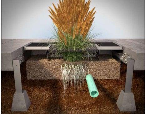
Water Quality Volume (WQv) Rainfall
Depends on SCM Group (see Section 5.7.4 below) OTHER SCM ATTRIBUTES
(cost
Channel Protection Volume (CPv) No
Detention / Retention Control No
Small Storm Local Flood Control No
Typical SCM Footprint Size (percent of contributing drainage area) Minor
Construction Cost $$
Operation & Maintenance Cost (when properly maintained) Varies by type
Overview
Manufactured treatment devices (MTDs) are pre-manufactured structural stormwater control measures (SCMs) that are purchased from a manufacturer or vendor and installed onsite (sometimes requiring onsite assembly). The purpose of the MTD is to remove pollutants from the stormwater that passes through them. Some MTDs use low impact development methods to remove pollutants using soil infiltration, biofiltration, and plant evapotranspiration.
(Photo source: Hydro International)
ADVANTAGES/BENEFITS
Application flexibility: A wide variety of MTDs are available in many different types, configurations, and sizes
Often includes all necessary components (inlets, pretreatment, main treatment, outlet, and overflow)
Very small to no surface footprint
Good for high impervious and high density developments with no room for SCMs with larger footprints
Some types are useful for hotspots and pollutants other than TSS
Manufacturers/vendors often provide support for MTD design, construction, and maintenance
DISADVANTAGES/LIMITATIONS
MTDs that serve developments where litter/floatables are common (e.g., fast-food restaurants) will require frequent cleaning
Some MTDs require regular replacement of components
Repairs can be costly; damage may require replacement of the entire MTD
Should not be made operational until site construction is complete
DESIGN CONSIDERATIONS FOR LOCATION, SIZING, & COMPONENTS
Requires NJDEP certification of MTD pollutant removal capability
Both local government and manufacturer specifications apply
DESIGN CONSIDERATIONS FOR LONG-TERM PROTECTION
Most components are located underground; additional protective features are typically minimal
Signs, stamps, or placards can be helpful in MTD awareness
DESIGN CONSIDERATIONS FOR LONG-TERM MAINTENANCE
See Table 5.7.2 MTD Feasibility Guidelines by Land Use and MTD Group
Primary routine maintenance activities will be drainage area cleaning (e.g., street sweeping), and device cleaning
Provide trash cans and pet waste stations in the drainage area as these may allow a reduction in the frequency of MTD cleaning
Northeast Tennessee Water Quality SCM Manual
5.7.1 General Description
MTDs are structural SCMs constructed by commercial manufacturers at an offsite location before they are installed and connected to the onsite stormwater system. Their purpose is to capture pollutants in stormwater runoff before they are conveyed to the downstream stormwater drainage system, another SCM, or a local waterbody. Most MTDs are installed underground and thus have a very small or even zero surface footprint. This makes them an attractive option for property owners, especially on small, space-limited sites where most other SCMs can take up a significant amount of land.
When MTDs were first introduced as “flow-through” devices, they operated very differently from more traditional SCMs, such as an extended detention pond or sand filter. They removed pollutants much more quickly. In general, older MTD designs can be grouped into two categories depending on their treatment type
Filtration MTDs operate via chemical or physical filtration using screen, cartridge, and granular media filter systems These MTDs are included in this design specification in the Group 3 MTD category. Examples are shown in Figure 5.7.1.1, although there are many more manufacturers and MTDs than are shown.
Hydrodynamic MTDs operate using mechanical or gravity separation, such as a hydrodynamic separator or baffle box settling system. These MTDs are included in this design specification in the Group 4 MTD category. Examples are shown in Figure 5.7.1.2 There are many more manufacturers and MTDs than shown in the figure.
Figure 5.7.1.1 Examples of Group 3 (Filtration) MTDs
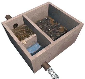
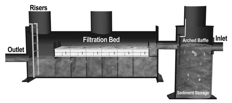
Figure 5.7.1.2 Examples of Group 4 (Hydrodynamic) MTDs


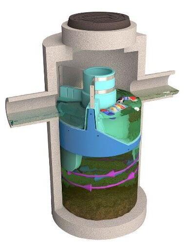
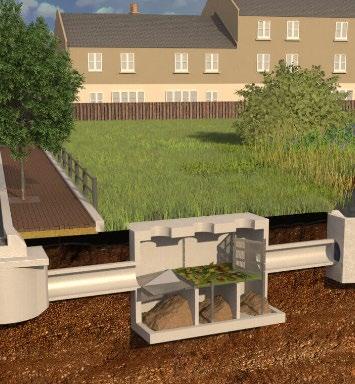
Top left: This graphic generally shows the operation of a Contech StormFilter® MTD. Blue arrows have been added to show the direction of flow for pollutant removal. (Adapted from a graphic by Contech Engineered Solutions ); Top right: Schematic of an AquaFilterTM Stormwater Filtration System by AquaShield (Source: Aquashield).
Left: A Cascade Separator® ready for installation (Source: Contech Engineered Solutions); Middle: Graphic of internal components of a Downstream Defender® hydrodynamic separator by Hydro International; Right: Baffles and screens in a Hydro DryScreen Separator (Source: Hydro International)
Northeast Tennessee Water Quality SCM Manual
Filtration and hydrodynamic MTDs are still available today and are included in this design specification as Group 3 and Group 4 SCMs, respectively. They have very little detention time and are generally good at removing trash, debris, and gross solids. These characteristics make them particularly useful as pretreatment devices for other, larger SCMs, such as extended detention ponds. These MTD designs can sometimes be adapted to address pollutants other than total suspended solids (TSS), such as petroleum, metals, etc., thus allowing their use for special pollutant abatement purposes. In the mid-2010s, the United States Environmental Protection Agency (USEPA) and state regulatory authorities began to emphasize “green infrastructure” (i.e., the use of infiltration, biofiltration, and evapotranspiration) as the most desirable approaches for pollutant removal. Many MTD manufacturers have green MTDs, henceforth called LID-MTDs, to their product lines. Today, there are a wide variety of LID-MTDs available in the commercial marketplace, with nearly all characterized by a compact surface footprint. They are included in this design specification as Group 2 MTDs. Examples of Group 2 MTDs are shown in Figure 5.7.1.3. There are many more manufacturers and MTDs than shown in the figure.
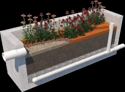
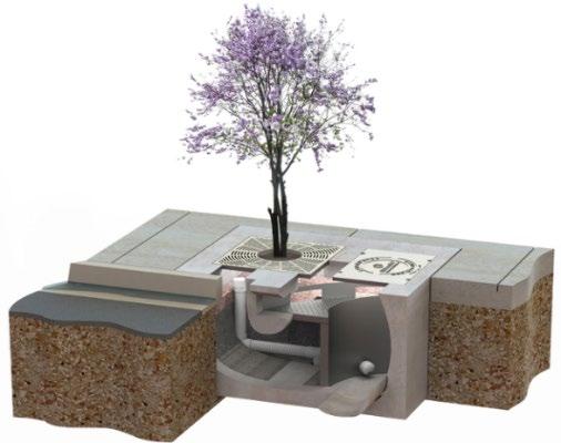
Group 1 MTDs operate via infiltration and evapotranspiration of stormwater and do not have an underdrain. Thus, they do not discharge stormwater to the onsite stormwater drainage system. At the writing of this manual, Group 1 MTDs could not be found for examples or further discussion. However, it is conceivable that these MTDs may become available in the future.
5.7.2 Third Party MTD Certification
The pollutant removal capabilities of MTDs have historically been difficult to determine. MTD performance is influenced by many factors, including influent particle size distribution, flow rate, device configuration, site conditions, pollutant types, etc. These variables make MTD testing to verify a manufacturer’s stated pollutant removal percentages a significantly costly and time-consuming effort. As MTDs have become more popular in the United States, third-party MTD testing collaboratives or initiatives have emerged to provide an objective evaluation of MTD pollutant removal. One of the most robust and comprehensive of these is the collaboration of the New Jersey Corporation for Advanced Testing (NJCAT) with the New Jersey Department of Environmental Protection (NJDEP).
NJDEP certification is required for MTDs proposed for developments within the jurisdiction of the local governments using this manual. This assures the local government that MTDs used within its jurisdiction are capable of protecting water quality. For the developer and design professional, it ensures their money is well-spent. Additional information about this collaborative and the NJDEP certifications are found at https://www.nj.gov/dep/stormwater/treatment.html
Figure 5.7.1.3 Examples of Group 2 (Biofiltration) MTDs
Left: StormVault Biofiltration Planter (Source: Jensen Precast); Right: Filterra® bioretention MTD (Source: Contech Engineered Solutions)
Northeast Tennessee Water Quality SCM Manual
5.7.3 Limitations of this Design Specification
The criteria provided in the remainder of this design specification are limited to policies regarding MTD selection, location, usage, and sizing. Beyond the policies provided herein, design professionals must work with a commercial MTD manufacturer/installer to ensure proper selection and installation of MTDs
5.7.4 MTD Groups
As with SCMs, MTDs are categorized into the same groups based on their treatment method. Table 5.7.4.1 defines and describes the groups for MTDs. These groups match the SCM groups, with the exception of the fifth group, called “Other’.
5.7.4.1 MTD Groups by WQv Treatment Method
Group WQv Treatment Method Description
1 Infiltration, evaporation, transpiration, or rainfall harvesting and reuse
2 Biologically active filtration with an underdrain
3 Sand or gravel filtration, settling
4 Pollutant/stormwater separation
Other Depends on pollutant(s) of concern
5.7.5 Design and Construction Policies
MTDs that remove stormwater volume through infiltration of stormwater into the in-situ soil. No underdrain.
MTDs that remove pollutants by filtering water through a planted soil/media bed, before discharging through an underdrain to the onsite stormwater system. Note: 12-inches of internal water storage is required for a Group 2 MTD. Thus, most MTDs in this Group will have to add a stone layer to meet this requirement.
MTDs that remove pollutants using removable/replaceable filters, inserts, or screens and/or media-filled cartridges, before discharging to the onsite stormwater system. Group 3 MTDs do not include drain filters, such as downspout filters, catch basin inserts, drop inlet baskets/filters, curb inlet inserts, and similar devices.
MTDs that use hydrodynamic forces (e.g., centrifugal) or gravity to remove pollutants, before discharging to the onsite stormwater system. Group 4 MTDs can also be used as pretreatment devices for other SCMs, etc.
MTDs that are designed to treat pollutants other than, or in addition to, TSS
The following policies shall apply to MTDs proposed in a water quality management plan (WQMP)
1. MTD design. All MTDs are considered SCMs and therefore are subject to all City requirements pertaining to SCMs They shall be designed in keeping with this design specification (i.e., the entirety of Section 5.7), the manufacturer’s specifications for the exact MTD make(s), model(s), and size(s) proposed for a land development, and any design caveats established by the independent third-party agency certifying, verifying, or confirming that TSS removal percentage, such as a maximum flow rate and MTD scaling, to ensure the pollutant removal effectiveness of the proposed MTDs as defined in the third-party certification.
2. NJDEP-certification of pollutant removal capability required. With the exception of Group 1 MTDs, NJDEP certification of the pollutant removal efficiency (in %) is required for MTDs proposed for use within the local government jurisdictions using this manual
NJDEP certifications are found at https://www.nj.gov/dep/stormwater/treatment.html and must be provided with the WQMP and the SCM Record Drawing. The MTD inspection and maintenance guides developed by the MTD manufacturer must also be included.
Table
Northeast Tennessee Water Quality SCM
3. Minimum % TSS Removal for MTDs. The minimum TSS removal percentage for MTDs included in designs for purpose of compliance with the Stormwater Quality Treatment (WQv) Standard is 50%. Note: MTDs that cannot achieve 80% TSS removal or greater must be placed in a treatment train to achieve the required 80% standard, or exchanged with an alternate SCM that can achieve the 80% standard
4. Situations where MTDs are required. MTDs from Group 3 (filtration) or Group 4 (hydrodynamic) are required as pretreatment measures or for full compliance with the City stormwater management requirements for the land uses listed below.
Parking lots with more than 100 parking spaces
Gas stations, automobile repair centers, and storage facilities for petroleum products
Any other land use that may have a higher-than-normal potential for pollutant discharges, as deemed appropriate by the local government.
MTDs selected for these situations must be designed with a minimum of 60 gallons of internal volume dedicated to the storage of spilled petroleum. This extra storage provides time for spill recovery crews to remove the petroleum before it discharges from the MTD.
5. MTD usage guidelines. Prior to selection for a site, MTDs shall be evaluated for their appropriateness for the onsite conditions, the pollutants expected at the site, and the potential for effective long-term maintenance by the owner(s) in keeping with the MTD maintenance plan. Table 5.7.5.1 presents MTD feasibility guidelines by MTD group and land use. Additional MTD usage policies follow the table. Table 5.7.5.2 lists the locations where MTDs cannot be used
Drainage areas with soil contamination or special (i.e., non-TSS) pollutants
(in lieu of a sediment forebay)
“Yes” indicates MTDs in the group are generally suitable for the land use.
“No” indicates the MTDs in the group are generally prohibited for the specified situation or land use.
“Limited” indicates the MTDs in the group have limited suitability, based on site conditions, expected pollutants, or concerns about required maintenance and future owner capabilities to effectively inspect and maintain the MTD. The local government will consider these concerns when evaluating the MTD for a proposed development
Table 5.7.5.1 MTD Feasibility Guidelines by Land Use and MTD Group
Table 5.7.5.2 Prohibited Locations and Uses
Location or Use
Federal Emergency Management Agency (FEMA)-designated Special Flood Hazard Areas (SFHAs) or floodplains in general.
Wellhead protection areas or groundwater recharge protection areas.
Developments where a prior land use on or near the property resulted in, or in the potential for, pollution of the soil with toxic or hazardous chemicals, pathogens, petroleum products, or other contaminant(s).
Locations where wet soil or groundwater from infiltration of runoff from the MTD into the surrounding soil can damage or otherwise negatively impact nearby utilities, road bases, building foundations, basements, crawl spaces, or areas of cultural, historic, or archeological significance.
Like all SCMs, MTDs shall not be used to treat the pollutants listed below unless specifically designed to do so. Information and design specifications from the MTD manufacturer indicating MTD suitability for such pollutants are required for local government approval.
Construction sediment/waste
Landscape storage or waste
Sewage, pet, and livestock waste
Medical waste
Household & commercial wastes
Hazardous wastes
Gasoline, motor oils, greases, and other petroleum-based products
Fats, oils & grease (from food preparation)
Pesticides, fertilizers, herbicides
Other byproducts and waste materials expected, based on the property’s land use
Groups 1 and 2
Group 1
Group 1
Group 1
All groups
6. Infiltration Feasibility Requirements for Group 1 MTDs. Group 1 MTDs shall not be approved unless ALL of the following conditions are met:
The SCM will be constructed in uncompacted, native soil that has an infiltration rate between 0.5 and 11 inches/hour, and only if these soil conditions can be maintained throughout construction of the land development.
Sufficient protection measures to prevent soil compaction within and around the bioretention area after construction are included in the design.
The development and the SCM meet all infiltration feasibility factors established in the Infiltration Feasibility Form provided in Appendix C (Infiltration Feasibility Form).
Infiltration tests are required for Group 1 MTDs before and after installation. See Appendix F (Policies for Soil Infiltration Tests & Soil Borings) for infiltration test requirements.
Although unlikely, Group 1 MTDs may be subject to a Class V Injection Well Permit pursuant to Tennessee Rule 0400-45-06-.06. This permit may be avoided by ensuring the MTD excavation is wider than it is deep. When required by TDEC, a copy of the permit must be provided with the WQMP at the time of its submission for approval.
7. MTDs in Treatment Trains. MTDs that cannot treat the required water quality control volume/peak rate for its contributing drainage area must be used in a treatment train or replaced with an alternate SCM that can treat the entire WQv. When MTDs are used in a treatment train, the policies and calculations in Section 5.7.7 (below) shall apply.
8. Flow diverter design. When MTDs are selected for installation in an off-line configuration, the design of the flow diverter that manages discharges greater than the MTD’s design flow must be included in the WQMP.
9. Permanent MTD identification. Once installed, MTDs shall be identified using a sign, placard, or stamp that can be permanently affixed to a grate, manhole, or other above-ground element of the MTD
Northeast Tennessee Water Quality SCM
10. Construction sequencing/MTD protection. MTDs must be protected from inflows of construction sediment and waste. Ideally, they should be installed only after its contributing drainage area is fully and permanently stabilized. If this is not feasible, block the inflows to MTDs until full, permanent stabilization occurs.
11. MTD substitutions during construction. Deviation from the make, model, size, number, and design of an MTD shown in an approved WQMP is prohibited without prior written approval for MTD substitution from the local government. The local government may require resubmittal of the WQMP with the substituted MTD to provide approval. In any case, the Record Drawing shall provide accurate information for the MTD(s) installed onsite.
Failure to obtain prior written approval for MTD substitutions may result in delays in construction inspections, approvals, or obtaining Temporary or Permanent Certificates of Occupancy.
5.7.6 MTD Sizing
See Chapter 3, Section 3.2.5 (Calculating the Water Quality Peak Discharge) for the sizing method for MTDs in Groups 1 and 2. The sizing method for MTDs in Groups 3, 4, and 5 is below. When sizing MTDs, design professionals shall adhere to sizing qualifiers related to the verified pollutant removal efficiencies that are provided by approved third party MTD certification agencies. Such qualifiers can include, but are not limited to, a maximum flow rate, hydraulic loading rate, and MTD scaling.
MTDs in Groups 3, 4, and 5 must be sized for the maximum runoff generated from the 1-year, 24-hour design storm. This requires use of a different calculation procedure than that used for MTDs in other tiers to determine the water quality peak discharge (Qwq). Equation 1 shall be used to design Tier 4 MTDs.
Equation 1
������������ = ������������
where: Qwq = maximum water quality peak discharge (cfs)
C = Rational Method runoff coefficient for the drainage area (C = 0.95 for 100% impervious areas, otherwise see Chapter 3, Section 3.2.5).
i = rainfall intensity for 1-year, 24-hour storm at the location of the MTD (inches/hour); see steps 1 and 2 below
A = area draining to the MTD (acres)
The following steps explain how the rainfall intensity (i) is determined.
Step 1. Determine the maximum time of concentration (Tc) for the MTD’s drainage area using NRCS 1 methods.
Step 2. The rainfall intensity is found using published precipitation frequency estimates published by the National Weather Service (NWS) Office of Water Prediction (OWP) in the NOAA 2 Precipitation-Frequency Atlas of the United States, latest edition This data is available on the NOAA Precipitation Frequency Data Server (PFDS) In the NOAA Atlas:
a. select the data description of precipitation intensity,
b. select the location by station or using the map function of the PFDS, at (or as close as possible to) the location of land development.
c. Find the data column for the 1-year, 24-hour storm. The rainfall intensity (i) is the value (in inches/hour) closest to the time of concentration (Tc) for the drainage area to the MTD.
1 NRCS is the acronym for National Resource Conservation Service, which was formerly named the Soil Conservation Service (SCS)
2 NOAA is the acronym for the National Oceanic and Atmospheric Administration
Northeast Tennessee Water Quality SCM
The example below illustrates how to determine Qwq
Example: Determine the Maximum Water Quality Peak Discharge, Qwq
A site designer has selected a hydrodynamic separator (an MTD from Group 4) for a proposed small commercial redevelopment in downtown Johnson City, TN. The development has a total area of 1.2 acres, all of which is impervious and located within a single drainage area. Determine the maximum water quality peak discharge, Qwq, to size the MTD.
Step 1: Using NRCS methods, the site designer determines the time of concentration, Tc, is 9.3 minutes.
Step 2: Using NOAA’s online Precipitation Frequency Data Server (PFDS), the site designer selects the “precipitation intensity” data description and navigates to the location of the redevelopment on the PFDS map. The resulting Point Precipitation Frequency Estimates table is partially shown in the screen capture below.
Step 3: The duration value in the table closest to the time of concentration, Tc, is 10 minutes. Thus, the rainfall intensity (i) is found for a rainfall having an average recurrence interval of 1-year and duration of 10 minutes. Thus, the rainfall intensity (i) = 2.96 inches/hour See the red box in the screen capture
Step 4: For Equation 1, C = 0.95 and A = 1.2 acres Using Equation 1:
Qwq = 0.95(2.96 in/hr)1.2 acres
Qwq = 3.37 cfs
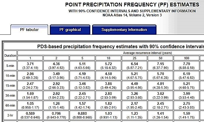
5.7.7 Using MTDs in a Treatment Train
A design option for SCMs that cannot manage the entire WQv, is to place it in a treatment train with an SCM. When an MTD is used in a treatment train, the following policies shall apply.
1. MTD placement: MTDs must always be the upstream SCM when placed in a treatment train.
2. Multiple MTDs prohibited: MTDs cannot be placed in a treatment train with another MTD.
3. TSS Removal Calculation: Treatment trains must provide an overall treatment efficiency of at least 80% total suspended solids (TSS) removal. Use Equation 2 and Table 5.7.7.1 to determine the total % TSS removal of the treatment train.
Equation 2 ���� = ���� + ���� (���� ���� ����) ������������
where: R = % TSS Removal for the treatment train
A = the % TSS removal applicable to the upstream SCM (this will be the MTD); use the certified % TSS removal (see Section 5.7.4 above)
B = the % TSS removal of the downstream SCM (from Table 5.7.7.1)
Table 5.7.7.1 % TSS Removal Values for SCMs when Used in a Treatment Train1
1 – The % TSS Removal values listed in the table are used when the SCM cannot manage the entire WQv for its drainage area and is placed in a treatment train with an MTD. If the SCM can manage the entire WQv as specified in Chapter 3, Table 3.1, then the SCM is presumed to achieve 80% TSS removal, per Tennessee Rule 0400-40-10-.04, and a treatment train is not necessary.
5.7.8 Vegetation Design (MTDs in Groups 1 and 2)
MTDs in Groups 1 and 2 include vegetation, which provide pollutant removal, runoff volume reduction, and visual appeal Their importance to MTD function means that plants, like any SCM component, have design, installation, maintenance, and replacement specifications. Plants contained within the MTD must be in keeping with plant specifications provided by the manufacturer. In the event the manufacturer does not provide plant specifications, or the local government finds the manufacturer’s information inadequate to fully display the intended vegetation for the MTD in the WQMP, the design professional may be required to provide a vegetation plan.
5.7.9
Protection Design
SCMs designed for stormwater quality purposes, including MTDs, must be maintained in keeping with the approved SCM design for the life of the land development 3 . Design professionals can assist property owners with this requirement by including protective features in and around MTDs to limit the potential for damage by external factors.
Many MTDs are designed by their manufacturer with protection in mind. With most of the MTD’s components located underground, manhole covers, grates, or other protective devices are typically included to provide adequate protection from entries into the main treatment area in highly urbanized settings. Additional protection methods can include natural or decorative fencing, curbing/curb blocks, signs, stamps, or placards. The placement of trash cans around the development can also help limit the discharge of floatables to the MTD.
5.7.10 MTD Maintenance on an Active Construction Site
Maintenance of SCMs, including MTDs, is regulated by local government ordinance from the moment they are installed. MTDs must also pass a final inspection prior to construction termination. This inspection will be performed to ensure they are constructed in accordance with the approved WQMP, undamaged, and free of sediment and debris. Thus, MTD maintenance is good practice to ensure construction termination goes smoothly. Relevant policies are as follows:
The property owner is responsible for MTD maintenance. If the property is still an active construction site, these responsibilities may fall to the land disturbance permittee until the project receives final approval from the local government and/or a Certificate of Occupancy.
Property owners may have others, such as a site contractor or landscaping company, maintain the MTD on their behalf. However, the local government will hold the property owner responsible for ensuring it is maintained in proper operating condition (i.e., as designed and constructed) regardless of who performs maintenance activities.
3 Tennessee Department of Environment and Conservation Rule 0400-40-10-.04
Northeast Tennessee Water Quality SCM
Maintenance activities, which include ensuring proper operation of the MTD as designed and required MTD inspections, must begin immediately following installation of the MTD.
Maintenance activities shall be performed in keeping with the Northeast Tennessee SCM Inspection and Maintenance Manual. Additional guidance on maintenance of newly installed MTDs located on active construction sites is provided in Table 5.7.10.1
Table 5.7.10.1 Maintenance Activities for Newly Installed MTDs
Area or Component
Contributing Drainage Area
Entire MTD
Keep the contributing drainage area clean and fully stabilized to prevent erosion. Sweep trash, debris, and sediment frequently so that it does not wash in the MTD during a rain event.
Cover stockpiles of construction and landscape materials to prevent their exposure to rainfall.
Block stormwater inflows to the MTD until the development is permanently and fully stabilized.
Inspect the MTD frequently and follow the manufacturer’s recommended activities for maintenance. Remove accumulated sediment, landscape debris, and trash from the MTD as often as possible
Inspect inlets and visible components of the MTD for clogging and damage; remove clogs and repair or replace damaged components as soon as they are noticed.
For Group 1 and 2 MTDs, maintain the plants (watering, weeding, etc.) in keeping with the manufacturer’s guidelines.
Alert onsite subcontractors to the SCM and the following requirements:
No muddy vehicles or equipment in the drainage area to the MTD.
Education
No stockpiling or dumping of material, including landscape debris, into the MTD.
Do not blow leaves or lawn clippings into the MTD.
Remove sediment, trash, debris, and empty trash cans in the drainage area frequently.
End of manufactured treatment device design specification
5.8 Permeable Pavement Systems
design specification
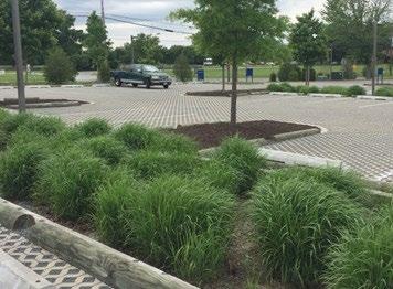
Overview
Channel Protection Volume (CPv) Yes
Detention / Retention Control Yes
Storm Local Flood
Cost
& Maintenance Cost (when properly maintained)
SCM Group(s): 1 & 3
Permeable pavement systems are green infrastructure (GI) stormwater control measures (SCMs) that function as both a stormwater control facility and useable pavement (e.g., parking spaces, parking lanes, walkways, etc.). The rainfall that falls on the pavement soaks into an underlying stone reservoir through voids in the pavement surface. It either infiltrates into the native soil below (Group 1 design configuration) or is collected by an underdrain that discharges to the onsite stormwater conveyance system (Group 3 configuration). These SCMs can also accept and treat stormwater from other areas of the land development.
ADVANTAGES/BENEFITS
Multi-functional SCM reduces post-construction stormwater rates, volumes, and pollutant loads without consuming valuable land for a single-function stormwater SCM
Particularly well suited for use on urban development sites and in low-traffic areas, such as overflow parking lots
Can be used for detention as well as water quality control
DISADVANTAGES/LIMITATIONS
Relatively high construction costs, which are typically offset by savings on stormwater infrastructure (e.g., storm drain system)
Systems should be installed only by experienced personnel
DESIGN CONSIDERATIONS
SCM should be designed to completely drain within 48 hours
An underdrain is not required if the pavement is located in native soil that has an infiltration rate between 0.5 in/hr and 11 in/hr
The distance from the bottom of the practice to the top of the seasonal high-water table should not be less than two 2 feet
LONG-TERM PROTECTION CONSIDERATIONS
Protect from materials that could cause clogging and failure of system (e.g., mulch, soil, sand, sediment/debris, leaf litter, etc.)
Educational signage, curbs, and decorative walls work well for protective designs
LONG-TERM OPERATION AND MAINTENANCE CONSIDERATIONS
Operational factors include structural surface integrity, clogging/damage, cleanliness, and surrounding area maintenance
Regular landscape maintenance (e.g., debris removal, weeding, pruning, plant removal and replacement, mulching)
Periodic cleaning of landscape debris, trash, and sediment from the permeable pavement and its drainage area
Subsurface clogging may require replacement of subsurface layers or pavement surface(s)
5.8.1 General Description
There are a variety of permeable pavement surfaces available in the commercial marketplace each of which is briefly described below.
Permeable Paver Systems: A pavement surface composed of structural units with void areas that are filled with pervious materials such as gravel, sand, or grass turf. Permeable paver systems are installed over a gravel base course that provides structural support and stores stormwater that infiltrates through the system into the underlying permeable soils or into an underdrain connected to the stormwater conveyance system. Permeable pavement systems are generally designed and installed by the manufacturer. Many vendors offer maintenance packages. Three basic types of permeable paver systems are discussed below.
Permeable Pavers. Permeable pavers are solid structural units (e.g., blocks, bricks) that are installed in a way that provides regularly spaced openings through which rainfall and stormwater can rapidly pass through the pavement surface and into the underlying stone reservoir (Figure 5.8.1.1a). The regularly spaced openings, which generally make up between 8% and 20% of the total pavement surface, are typically filled with pea gravel. Typical permeable paver systems consist of the pavers (typically 1.5 to 3 inches thick), a fine gravel bedding layer, and an underlying stone reservoir.
Concrete Grid Pavers. Concrete grid pavers are precast concrete units that allow water to pass through large openings that are filled with gravel, sand, or topsoil and turf (Figure 5.8.1.1b). Concrete grid pavers are typically 3.5 inches thick and have a void ratio between 20% and 50%. This means the material used to fill the spaces between the grids has a large influence on the overall permeability (i.e., void space) of the system. A typical installation consists of the pavers, a 1 to 1.5 inch sand or pea gravel bedding layer, and an underlying stone reservoir. “Void structured concrete” is a design variation that uses molded cast-in-place concrete rather than pavers.
Plastic Grid Pavers. Plastic grid pavers are similar to concrete grid pavers, but use flexible, interlocking plastic units to provide strength and structure. The units allow rainfall and stormwater to pass through large openings that are filled with gravel, sand, or topsoil and turf (Figure 5.8.1.1c). Since the empty plastic grids have a void ratio of between 90% and 98%, the material used to fill the spaces between the grids has a large influence on the overall permeability (i.e., void space) of the system.
Pervious Concrete. Pervious concrete (also known as porous concrete) is similar to conventional concrete in structure and form but consists of a special open-graded surface course, typically 4 to 8 inches thick, that is bound together with Portland cement. This open-graded surface has a void ratio of 15% to 25% (conventional concrete pavement has a void ratio of between 3% and 5%), which gives it a high permeability that allows rainfall and stormwater to rapidly pass through it into the underlying stone reservoir (Figure 5.8.1.1d). Although this system may not need an underlying base layer to support traffic loads, a base layer can increase the water
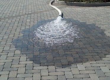

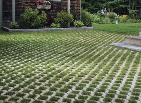
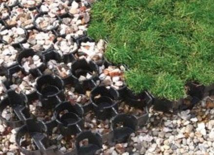
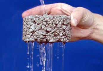
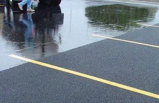
Figure 5.8.1.1e Porous Asphalt
Figure 5.8.1.1b Concrete Grid Pavers
Figure 5.8.1 1a Permeable Pavers
Figure 5.8.1.1c Plastic Grid Pavers
Figure 5.8.1.1d Pervious Concrete
Figure 5.8.1.1 Permeable Surfaces
Northeast
storage capacity. Pervious concrete applications are generally designed by the site’s design engineer and installed by a local concrete company.
Porous Asphalt. Porous asphalt consists of standard bituminous asphalt in which the fine particles have been screened and reduced, creating void spaces that allow the surface to be highly permeable to rainfall and stormwater. Porous asphalt often has a lower construction and maintenance burden than permeable pavers and pervious concrete. (Figure 5.8.1.1e). The void space of porous asphalt is approximately 16%, as opposed to two to three percent for conventional asphalt. Designs typically consist of at least four layers: a 2 to 4 inch layer of asphalt; a 1 to 2 inch filter layer of half-inch crushed aggregate; a 12 inch minimum reservoir layer of 1 to 3 inch aggregate; and a layer of geotextile material. As with pervious concrete, porous asphalt is usually designed by the site’s design engineer and installed by a local paving company.
5.8.2 Design Applications
Permeable pavement systems are highly versatile SCMs appropriate for numerous design applications (depending on the type), including parking lots, on-street parking lanes, driveways, sidewalks, bike paths, playgrounds, and tennis courts. They are commonly used in commercial, institutional, and residential areas that have traditionally been surfaced with impermeable concrete or asphalt. There are few limits on their geometry which means they can be sized to fit into tight site layouts. Additionally, permeable pavements can be especially helpful in developed areas with little open space that cannot accommodate SCMs that require dedicated surface area (e.g., bioretention areas and extended detention basins). With proper design and maintenance, this SCM can have a very long service life and so is a great alternative in highly impervious or space-constrained high traffic areas (see Figure 5.8.2.1).
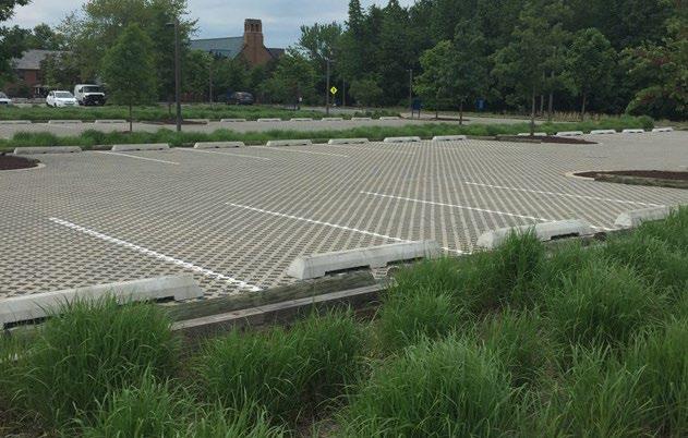
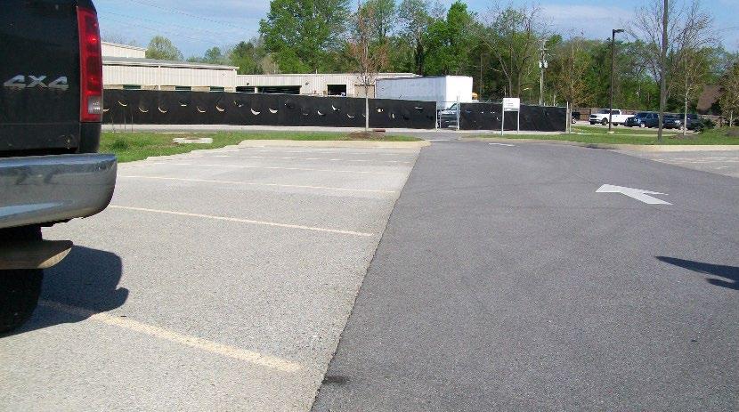
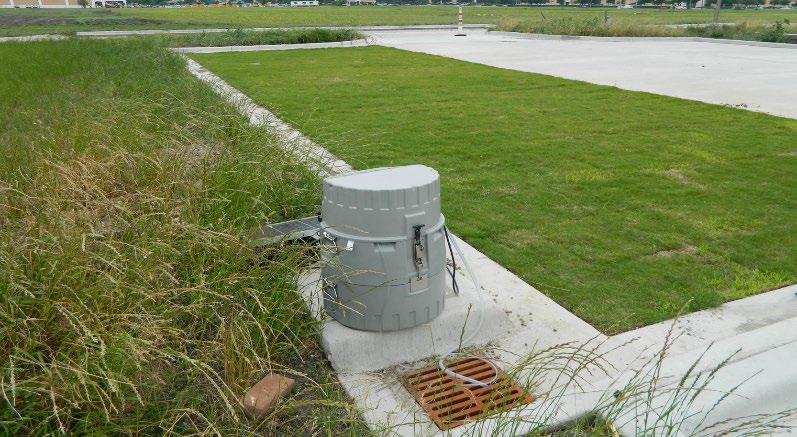
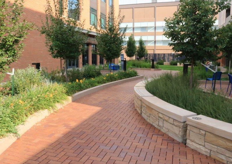
Figure 5.8.2.1 Examples of Permeable Pavement Systems Applications
(Top left: St. Mary’s College, MD parking lot with concrete grid pavers filled with gravel; Top right: Plastic grid pavers filled with grass used at the Texas AgriLife Center in Dallas, TX (Source: Texas A&M University); Bottom right: Permeable pavers used in walkway (City of Boulder CO); Bottom left: Parking lot with pervious concrete parking spaces (Hallsdale Powell Utility District, Knox County TN).
Permeable pavement systems can manage both the rainfall that falls on their surface and stormwater discharged to the pavement from other impervious areas (called “run-on”). For example, roof downspouts can discharge to a properly sized permeable pavement system, thus allowing the SCM to manage stormwater for large impervious surfaces (see Figure 5.8.2.1). This flexibility can decrease the necessity for extra spending and land utilization linked to traditional collection, conveyance, and management infrastructure.
Figure 5.8.2.1 Permeable Pavement Systems and Run-on
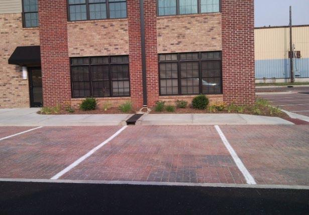

Impervious driveway Permeable pavers

5.8.3 Water Quality Management Plan (WQMP) Applicability

In an example of run-on to a permeable pavement system, the permeable paver parking lot is sized to manage the rainfall on the pavers, and run-on from the impervious driveways, sidewalks, and roof. Roof downspouts discharge to the permeable paver surface (The National Apartments located in Indianapolis IN)
Permeable pavement systems reduce the effective impervious cover of a development site by mimicking an undeveloped (i.e., pervious) surface area, but only to the degree their storage capacity allows. Thus, if the system is designed to manage the WQv alone, the system is permeable/pervious for the water quality rainfall (i.e., 1.0 to 2.5 inches depending on design) alone. As the depth of rainfall from a storm exceeds a pavement system’s storage capacity, or the rainfall intensity exceeds the system’s infiltration rate, the pavement no longer reduces stormwater volumes until storage becomes available again In this situation, the pavement system responds to rainfall like an impervious surface in that it generates stormwater that runs off its surface and discharges to the onsite stormwater infrastructure. So, the larger the storage capacity of the pavement system, the longer the pavement will remain hydrologically “pervious” during a storm event.
For this reason, all areas of a site must be accounted for as impervious surface area for assessing whether a site qualifies for an exemption from Water Quality Management Plan (WQMP) requirements. Proposed permeable pavements cannot be used to exempt a proposed development from stormwater requirements and avoid the design and approval of a site’s stormwater infrastructure. A proper design in a fully detailed WQMP is necessary to ensure the site is designed to manage stormwater from ALL design storm events, even for small sites that are on the edge of stormwater management requirement applicability.
5.8.4 General Material Specifications
Permeable pavement material specifications vary according to the specific pavement product selected. Table 5.8.4.1 provides a general comparison of material specifications for different permeable pavement types. The table is provided as general guidance only to assist in understanding of different types of permeable pavement systems. Similar information from individual pavement system manufacturers may differ.
Table 5.8.4.1 Comparison of General Material Specifications by Permeable Pavement Type
Material
Permeable Pavers
Surface open area: 5% to 15%.
Thickness: minimum three (3) inch width for standard passenger vehicles and low traffic uses. May be higher for heavier loads and high-traffic applications.
Compressive strength: 55 MPa
Open void fill media: aggregate.
Conformance with ASTM C936 specification.
Material
Concrete Grid Pavers
Plastic Reinforced Grid Pavers
Specification
Open void content: 20% to 50%
Thickness: minimum 3.5 inches.
Compressive strength: 35 MPa
Open void fill media: aggregate, topsoil/grass, coarse sand.
Void content: depends on fill material.
Compressive strength: varies, depending on fill material.
Open void fill media: aggregate, topsoil/grass, coarse sand.
Open void content: 16% to 22%.
Thickness: typically, two (2) to six (6) inches
Porous Asphalt
Pervious Concrete
5.8.5
Notes
Conformance with ASTM C1319 specification.
Compressive strength:
Open void fill media: None
Void content: 15% to 25%
Thickness: typically, four (4) to eight (8) inches.
Compressive strength: 2.8 to 28 MPa
Open void fill media: None.
SCM Suitability
Since permeable pavement has a very high stormwater reduction capability, it should always be considered as an alternative to conventional pavement. Use Table 5.8.5.1to determine if a permeable pavement system is suitable for the application being considered.
Table 5.8.5.1 Permeable Pavement System Suitability Factors
Stormwater Quality Treatment
Permeable pavement systems designed in keeping with the specifications established herein will satisfy local government stormwater quality treatment standards
Channel Protection
Permeable pavement systems designed as Group 3 SCMs that manage the entire WQv for their contributing drainage area also satisfy the local government CPv standard for their contributing drainage area without additional design requirements.
Detention
Pollutant Treatment
Capability
Permeable pavement systems can be designed to provide detention to meet local government flood control requirements.
Permeable pavement systems can be used to address the following common stormwater pollutants1:
1 Georgia Stormwater Management Manual, Volume 2 Technical Handbook, 2016 Edition.
* Cadmium, Copper, Lead, and Zinc
Treatment of Waste and Other Pollutants
Permeable pavement systems shall not be used to treat the following pollutants:
Construction sediment/waste
Landscape storage or waste
Sewage, pet, and livestock waste
Medical waste
Household & commercial wastes
Hazardous wastes
Gasoline, motor oils, greases, and other petroleum-based products
Fats, oils & grease (from food preparation)
Pesticides, fertilizers, herbicides
Other byproducts and waste materials expected, based on the property’s land use
Privately owned permeable pavement system SCMs are not allowed in the public right-of-way. General suitability criteria by land-use type for purposes of meeting local government stormwater management requirements are as follows. See Chapter 3, Standards, Methods, and SCM Selection for more information.
Suitability by Land Use
*These policies do not preclude the use of permeable pavement systems on individually owned single family or multi-family residential lots. However, systems placed on residential lots will not be considered by the local government as suitable for compliance with local government stormwater management requirements due to the inherent difficulties in oversight and enforcement of long-term protection and maintenance requirements on residential lots
5.8.6 SCM Location Requirements
Location constraints for permeable pavement systems are provided in Table 5.8.6.1
Table 5.8.6.1 Permeable Pavement System Location Requirements
Physical Element
Minimum SCM Setbacks
Flow Avoidance
Utility Avoidance
5.8.7
Requirement
Setbacks to structures and roads vary, based on the scale of the permeable pavement installation. At a minimum, small- and large-scale pavement applications shall be located:
15 feet down gradient from buildings (where this setback is infeasible, an impermeable liner may be used along the sides of the permeable pavement nearest the building foundation, extending from the surface to the bottom of the practice)
100 feet from private water supply wells
200 feet from public water supply reservoirs (measured from edge of water)
1200 feet from public water supply wells
50 feet from septic systems
at least 5 feet down-gradient from dry or wet utility lines.
Permeable pavement systems shall not be located where it will receive continuous or dry weather inflows from springs, seeps, sump pumps, wash stations, or other sources.
Permeable pavement systems shall not be located above underground dry utility lines (electric, cable, and telephone) and water/wastewater infrastructure. Consult the local utility to determine the horizontal and vertical clearance required between SCMs and dry and wet utility lines.
Design Requirements
The specifications in this document do not describe the complete design of a functional permeable pavement system. Beyond the design standards for WQv, CPv, and flood control to meet local government stormwater management requirements, design professionals must work with commercial permeable pavement system manufacturers/vendors and follow the manufacturer’s specifications for design and construction.
A generalized depiction of a Group 3 permeable pavement system cross section is provided in Figure 5.8.7.1. The underdrain would not be present for a Group 1 system. The minimum standards for permeable pavement system design are provided in Table 5.8.7.1
Figure 5.8.7.1 Generalized Permeable Pavement System Main Components (Group 3 Type)
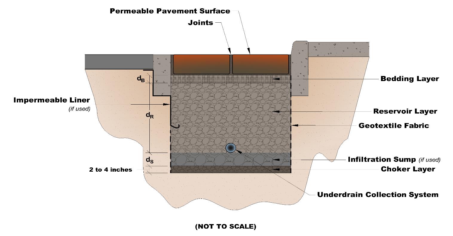
Table 5.8.7.1 Design Specification for Permeable Pavement Systems
Design Element
Specification(s)
Permeable pavement systems shall be designed with an underdrain collection system and without an infiltration sump unless ALL the following conditions are met:
Infiltration Feasibility Criteria
Class V Injection Well Permits
Water Quality Volume (WQv)
the SCM will be constructed in uncompacted, native soil that has an infiltration rate between 0.5 and 11 inches/hour, and these soil conditions can be maintained throughout the construction of the land development; and,
the development and SCM meets all infiltration feasibility factors established in the Infiltration Feasibility Form provided in Appendix C (Infiltration Feasibility Form).
Infiltration tests will be required both before and after permeable pavement system construction. See Appendix F (Policies for Soil Infiltration Tests & Soil Borings) for infiltration test requirements. Additional geotechnical information may be required by the local government.
Although unlikely, permeable pavement systems that do not have an underdrain may be subject to a Class V Injection Well Permit pursuant to Tennessee Department of Environment and Conservation (TDEC) rule 0400-45-06-.06. The requirement for a permit is determined by TDEC, not the local government. When a permit is required, a copy must be provided to the local government prior to, or with, the submission of the Water Quality Management Plan.
The water quality rainfall depth (P) for determination of WQv are as follows:
Permeable pavement without an underdrain (Group 1 SCM): P = 1.0 inch.
Design Element Specification(s)
Permeable pavement with an underdrain (Group 3 SCM): P = 2.5 inches or 75% of the total runoff volume from the 1-yr, 24-hr design storm, whichever is less. The design professional can select which volume to use.
In the WQv equation (Chapter 3, Equation 3.2.3.1), the SCM drainage area (A) is as follows:
If the pavement system is managing the rainfall that falls on the system only, A equals the surface area of the permeable pavement system itself.
If the pavement system will also manage stormwater from an adjacent impervious surface, A equals is the surface areas of both the system itself and the adjacent impervious surface.
Acceptable methods to determine WQv are presented in Chapter 3, Section 3.2.3 (Determining the WQv).
If the pavement system can treat the entire WQv for its contributing drainage area, additional SCMs for stormwater quality treatment are not required in the contributing drainage area.
Controls for Waste & Other Pollutants
Appropriate controls shall be included in the design of the permeable pavement system and any adjacent areas draining to it to address any wastes and other pollutants (see Table 5.8.5.1 above) that are expected after construction. Use the proposed land use as a guide to determine appropriate controls. Examples of such controls include, but are not limited to, dumpsters, trash cans, covered materials/waste storage areas, covered materials transfer areas, oil and grease waste controls, and pet waste stations.
Permeable pavement systems can be designed to provide detention for the local government’s specified design storm events as follows.
Detention (Flood Control)
Maintenance Access and Easement
The reservoir layer must be designed with consideration of the volume needed to detain the design storms (including chamber structures that can increase the available storage volume in the layer), expected exfiltration of water from the reservoir layer into the surrounding soil (if any), and any outlet structures used as part of the design.
Use routing calculations to provide a more accurate solution of the peak discharge and required storage volume.
Calculate outflow pathways to handle subsurface flows, which can be regulated using underdrains, the volume of storage in the reservoir layer, the bed slope of the reservoir layer, and/or a control structure at the outlet.
The entire permeable pavement system must be accessible for maintenance.
A maintenance easement to (and including) the permeable pavement system must be provided from a public roadway. The easement must be free of permanently affixed obstructions (e.g., trees, pools, fences without gates, permanent signs, etc.) to allow maintenance vehicles and equipment to safely pass.
Pavement Selection
Minimum Depth to Water Table
Drawdown Time
Permeable pavement system manufacturers typically provide substantial information to assist design professionals in the selection and design of the appropriate pavement system for the intended application and site characteristics.
Minimum separation distance (bottom of excavation to seasonally high-water table) = 2 feet
Soil borings shall be used to determine the seasonally high-water table. See Appendix F (Policies for Soil Infiltration Tests & Soil Borings) for soil boring requirements.
Group 1 permeable pavement systems (without an underdrain):
The WQv shall exfiltrate the bioretention area to at least 2 feet below the bottom of the area within 48 hours
Group 3 permeable pavement systems (with an underdrain):
The WQv shall fully discharge from the underdrain within 48 hours.
Design Element Specification(s)
Generally, Group 3 systems must be designed so the volume stored in the reservoir layer is detained for as long as possible (up to 48 hours) before completely discharging through the underdrain collection system.
Underdrain (Group 3 Systems only)
Internal Water Storage
5.8.8
Use the pavement manufacturer’s specification for the underdrain pipe. In the absence of manufacturer’s specifications, see Section 5.15 (Underdrain & Internal Water Storage). All underdrain designs shall include consideration of the expected use/loads/speeds the pavement will encounter (e.g., pedestrian traffic only, passenger vehicles only, etc.).
Internal water storage (also called infiltration sumps) is an additional storage volume layer designed to manage stormwater in excess of the WQv via exfiltration to the in-situ soil below the SCM. Infiltration sumps are optional features for both Group 1 and Group 3 permeable pavement systems. For more information, see Section 5.15 (Underdrains & Internal Water Storage).
Protection Design
SCMs designed for stormwater quality purposes must be maintained in keeping with the approved SCM design for the life of the land development (Tennessee Rule 0400-40-10-.04). Design professionals can assist property owners with this requirement by including protective features in and around SCMs to limit the potential for damage by external factors. Often, the landscape and impervious features around an SCM can be tailored to its specific needs.
For permeable pavement systems, protection is especially important to keep the pavement surface from clogging. These SCMs should be carefully located to minimize the amount of sediment, mulch, grass clippings, leaves, nuts, and fruits that will drop or be washed onto the pavement. Routine cleaning (blowing/sweeping) can mitigate this issue; however, where these materials will be significant year-round, use conventional pavement and select a different SCM to address stormwater treatment requirements. Protection methods for permeable pavement systems are listed in Table 5.8.8.1
Table 5.8.8.1
Permeable Pavement Protection Measures*
Protection Measures
Grade adjacent pervious areas to drain away from the permeable pavement system.
Locate trees and plants prone to dropping leaves, nuts, fruits, buds, or sap well away from the edges of the permeable pavement system.
Hardscaping to direct or contain debris within adjacent pervious areas
Educational or directive (e.g., no pets or maximum load) signs (see Figure 5.8.8.1).
Provide ample trash and cigarette disposal containers within the drainage area
Provide pet waste stations for systems located within or near pedestrian walking areas (e.g., sidewalks, trails, parking lots in recreational areas).
*The list presented in the table is not exhaustive. There may be other possible protection measures.
Figure 5.8.8.1 Examples of Permeable Pavement Protection Measures
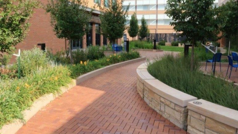
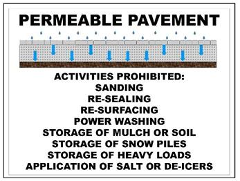
5.8.9 Site Preparation and Land Disturbance Requirements
The following information is provided to support proper and effective construction and protection of permeable pavement systems during land disturbance activities and site construction. Mandatory requirements are identified using “shall” or “must.” All other statements can be regarded as non-mandatory guidance. Site preparation and land disturbance practices described in this section shall be shown on the Erosion Prevention and Sediment Control (EPSC) plan for the proposed land development. Table 5.8.9.1 provides requirements for site preparation and land disturbance practices for land developments with permeable pavement systems.
Table 5.8.9.1
SCM
Site Preparation and Land Disturbance Requirements for Permeable Pavement Systems
Preservation of the native, uncompacted soil during site construction and construction phasing and sequencing are critical to the success of a Group 1 permeable pavement system. Thus, the following requirements apply:
The location of the permeable pavement system shall include a protection zone extending a minimum of 10 feet around the perimeter of the permeable pavement area and shall be protected from encroachments by vehicles, equipment, and workers during site construction. To the extent practical, work within the perimeter should be confined only to that required for installation of the permeable pavement system.
Permeable Pavement Systems Without an Underdrain (Group 1 SCMs)
The permeable pavement system protection zone shall be identified and marked prior to commencement of land disturbance activities using highly visible orange fencing (or similar visible protective measures) and signage to advise construction personnel not to enter the area. Construction vehicle and equipment parking, thoroughfares, wash-off areas, and sediment traps/basins shall not be located in the permeable pavement protection zone.
Clearing, grubbing, and grading using heavy equipment is prohibited in the protection zone. When these activities are necessary for the construction of the permeable pavement system, hand tools or smaller equipment that can reach into the protection zone must be used to avoid compaction of the native soil within the zone.
Erosion prevention and sediment control (EPSC) measures must safeguard the protection zone both prior to, during, and if necessary, after its installation.
Site construction shall be sequenced such that the permeable pavement system is installed only after the area draining to it has been fully and permanently stabilized
Left: Permeable pavement can be landscaped so that barriers, like curbing and walls, keep mulch, sediment, and plant debris within pervious areas (Source: City of Boulder CO); Right: Example layout for a sign to be located at a permeable pavement (Source: NCDEQ Stormwater Design Manual)
SCM Type Policy
Construction phasing and sequencing are critical to the success of Group 3 permeable pavement systems. Thus, the following requirements apply:
Permeable Pavement Systems with an Underdrain (Group 3 SCMs)
Permeable pavement systems can infiltrate stormwater even though they have an underdrain. This capability should be preserved during construction, if possible, by identifying and protecting the permeable pavement system location using highly visible orange fencing (or similar visible protective measures) and signage to advise construction personnel not to enter the area.
Construction vehicle and equipment parking, thoroughfares, roadways, parking, and washoff areas shall not be located where permeable pavement will be located.
The permeable pavement system shall be protected using erosion prevention and sediment control measures before, during, and, if necessary, after installation.
Site construction shall be sequenced such that the permeable pavement system is installed only after the area draining to it has been fully and permanently stabilized.
5.8.10 SCM Maintenance on an Active Construction Site
SCM maintenance is regulated by local government ordinances from the moment they are installed. As well, SCMs must pass a final inspection prior to construction termination. This inspection will be performed to ensure they are constructed in accordance with the approved WQMP, undamaged, and free of sediment and debris. Thus, SCM maintenance is a good practice to ensure construction termination goes smoothly. Relevant policies are as follows:
The property owner is responsible for SCM maintenance. If the property is still an active construction site, these responsibilities may fall to the land disturbance permittee until the project receives final approval from the local government and/or a Certificate of Occupancy.
Property owners may have others, such as a site contractor or landscaping company, maintain the permeable pavement system on their behalf. However, the local government will hold the property owner responsible for ensuring it is maintained in proper operating condition (i.e., as designed and constructed) regardless of who performs maintenance activities.
Maintenance activities, which include ensuring proper operation of the SCM as designed and required SCM inspections, must begin immediately following installation of the permeable pavement system.
Maintenance activities shall be performed in keeping with the Northeast Tennessee SCM Inspection and Maintenance Manual. Additional guidance on maintenance of newly installed permeable pavement systems located on active construction sites is provided in Table 5.8.10.1
5.8.10.1 General Maintenance Activities for Newly Installed Permeable Pavement Systems (all
types)
Activities
Construction sediment, materials stockpiles, and equipment and vehicles that exceed the pavement design loads are the most significant concerns for permeable pavement systems that are installed before active construction is complete. Employ the following activities to ensure the integrity of the pavement system is preserved throughout construction.
Keep the permeable pavement system clean, according to the manufacturer’s instructions and information in Tables 5.8.10.2, 5.8.10.3, 5.8.10.4, or 5.8.10.5.
Remove trash, debris, and sediment from adjacent areas frequently so they do not wash onto the permeable pavement system during a rain event.
Do not allow construction and landscaping materials to be stockpiled, loaded, unloaded, or transferred on the permeable pavement and impervious areas draining to it. If this cannot be avoided, place highly durable tarps on the pavement where these materials will be stockpiled, loaded, or transferred. Cover stockpiles entirely covered to prevent exposure to rainfall.
Stabilize pervious areas as soon as possible to prevent the discharge of construction sediment to the pavement. If unstable areas are still present, ensure that erosion protection and sediment control (EPSC) measures in these areas are maintained and effective. It may be necessary to use diversion measures to direct water away from the SCM until the area draining to it is stabilized.
Identify and cordon-off the permeable pavement from construction traffic to prevent heavy construction loads or tracking of construction-related sediments onto the permeable pavement area. Provide alternate routes for construction vehicles that avoid the pavement system and provide ample visual cues (signs, arrows, traffic barriers or cones, etc.) to ensure they can be seen and understood.
If the use of the pavement is necessary while construction is on-going, provide a fully paved, clean entry and exit location for access by non-construction vehicles only. DO NOT USE GRAVEL OR SIMILAR MATERIALS for this entry/exit, as they produce fine particles and dust when under vehicle/equipment loads, and tires will carry the particles onto the pavement. Over time, this will lead to pavement clogs in areas near the gravel and the need for repairs.
If necessary, cover the permeable pavement system to protect it from sediment tracking from light construction vehicles or construction foot traffic.
The rate of sediment deposition should be monitored and cleaning per manufacturer recommendations conducted frequently
Alert onsite construction and landscaping subcontractors to the presence of the permeable pavement system and advise them on the above rules, relevant to their onsite activities.
5.8.10.2 Additional Maintenance Activities for Permeable Paver Systems
Activities
The general maintenance guidelines, above, apply to permeable pavers. Following the manufacturer’s recommendation is best practice. Below are some guidelines specifically for permeable pavers.
Use a coarse-bristle “stable” broom to clean the surface of the pavers when sediment and debris are on the surface.
Weeds can grow quickly, even on active construction sites. Weeds can shift pavers apart over time. Apply a granular weed preventative between the joints during the growing season.
Do not use a high-pressure water system or compressed air units on permeable pavers, because they will push the particles deeper into the pavement.
Use a commercial vacuum sweeper to remove sediment accumulation and ensure continued porosity if necessary.
Table
Table
In the event of an oil spill, remove it promptly with granular oil absorbent. Spills should be soaked up, not rubbed. Rubbing will drive the stain deeper into the concrete.
Keep the joints topped off with sand to prevent the sand-bedding layer below from deteriorating, causing the pavers to shift.
5.8.10.3 Additional Maintenance Activities for Concrete Grid & Plastic Grid Pavement Systems
Activities
The general maintenance guidelines, above, apply to concrete and plastic grid pavement systems. Following the manufacturer’s recommendation is best practice. Below are some guidelines specific to concrete/plastic grid pavement systems, either filled with gravel, sand, or turf.
Grids filled with gravel or sand:
Sweep gravel/sand back into cells with a rake or broom.
If necessary, use a shop vacuum (6 horsepower or better) to remove a clog. The sand or gravel can be loosened to facilitate better cleaning before vacuuming. Rocks removed from the grid can be washed and put back into place.
Grids filled with turf:
Grids filled with turf should be mowed as appropriate for the grass species used
Do not aerate. Aeration can damage the pavement system’s base.
Protect from traffic until turf root system is well established.
Large oil/antifreeze spills will effectively sterilize affected soil for years and prevent growth of most vegetation. If this occurs, the soil, base course, rings, and grass should be replaced, and soil disposed of according to local codes relating to hazardous materials.
Table 5.8.10.4 Additional Maintenance Activities for Pervious Concrete
Activities
The general maintenance guidelines, above, apply to pervious concrete. Following the manufacturer’s recommendation is best practice. Below are some additional guidelines specific to pervious concrete.
Sediment can easily clog the pore space of pervious concrete. Using a leaf blower to remove light sediment and debris may be necessary. Additionally, a vacuum truck or walk behind unit may be needed to remove more significant sediment deposits.
Deep cleaning/unclogging is best accomplished by simultaneous pressure washing and vacuuming. Several equipment manufacturers have developed pressure washing/vacuum systems that have proven to rehabilitate the pore structure of pervious concrete.
If moss is visible on the pavement, it can be controlled by sprinkling baking soda on the surface, followed by a dry vacuuming within a few weeks to remove the debris
Use of chemicals to clean pervious concrete should be done with extreme caution to prevent damage to the aquifer, the biological organisms within the pervious system, or the pervious concrete pavement itself.
Table 5.8.10.5 Additional Maintenance Activities for Porous Asphalt
Activities
The general maintenance guidelines, above, apply to porous asphalt. Following the manufacturer’s recommendations is best practice. Below are some additional guidelines specific to porous asphalt.
Frequent broom sweeping of small areas and vacuuming large areas is recommended either with a truck or walk behind unit Vacuum sweepers can be fitted with water jets.
Table
Power washing is recommended for surface cleaning, especially in humid areas where moss may grow on the surface. Power washing should be followed up by sweeping or vacuuming to remove loosened particles
Specialized chemical combinations containing detergents and digesting agents can be applied to keep this debris from slowing down the pavement’s ability to drain water. Using safe digesting agents, coupled with cleaning agents that dissolve or emulsify these materials, will help restore the performance of these pavements.
5.8.11 References
American Society for Testing and Materials (ASTM). 2023. “Standard Specification for Solid Concrete Interlocking Paving Units”. ASTM C936. West Conshohocken, PA.
American Society for Testing and Materials (ASTM). 2023. “Standard Specification for Concrete Grid Paving Units”. ASTM C1319. West Conshohocken, PA.
ARC. Georgia Stormwater Management Manual Volume 2 Technical Handbook, 2016 Edition. Atlanta Regional Commission, 2016
Invisible Structures. Grasspave2 Maintenance Guide for Owners and Maintenance Staff. Online. Accessed January 2024. https://www.invisiblestructures.com/wp-content/uploads/GP2MaintenanceGuide.pdf
Jackson, N. 2007. Design, Construction and Maintenance Guide for Porous Asphalt Pavements. National Asphalt Pavement Association. Information Series 131. Lanham, MD. Available online at: https://www.asphaltpavement.org
Mrucagz, J. Wolf Paving. Asphalt Paving Blog. Online. November 20, 2018. Accessed January 2024. https://www.wolfpaving.com/blog/bid/85363/keep-your-porous-asphalt-pavement-looking-brand-new
National Ready Mix Concrete Association. Pervious Concrete Pavement and Operation Guide. Online. Accessed January 2024. https://www.perviouspavement.org/downloads/pervious_maintenance_operations_guide.pdf
North Carolina Department of Environmental Quality (NCDEQ). 2020. Stormwater Design Manual. Online. Accessed July 2024. https://www.deq.nc.gov/about/divisions/energy-mineral-and-land-resources/stormwater/stormwaterprogram/stormwater-design-manual
Tennessee Department of Environment and Conservation. Underground Injection Control. Nashville, TN. https://publications.tnsosfiles.com/rules/0400/0400-45/0400-45.htm
Tennessee Department of Environment and Conservation. National Pollution Discharge Elimination System General Permits. Nashville, TN. https://publications.tnsosfiles.com/rules/0400/0400-40/0400-40.htm
TRUEGRID® Paver. Maintenance Tips for Permeable Paver Performance. Online. Accessed January 2024. https://www.truegridpaver.com/permeable-paver-maintenance/
design specification
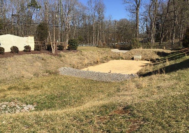
Water Quality Volume (WQv) Rainfall
Group 3 Design
P = 2.5 inches or the first 75% of the volume from the 1-yr, 24-hr storm, whichever is less
OTHER SCM ATTRIBUTES (cost
Channel Protection Volume (CPv) Yes
Detention / Retention Control No
Small Storm Local Flood Control Minor
Typical SCM Footprint Size (percent of contributing drainage area) Varies by type Construction Cost
& Maintenance Cost (when properly maintained)
SCM Group: 3
Overview
Sand filters are structural stormwater control measures (SCMs) with multiple chambers designed to treat stormwater through filtration, using a sediment forebay, a sand bed as the primary filter media, and an underdrain system. This design specification addresses the three types of sand filters: surface, perimeter, and underground (Photo on the left courtesy of the City of Concord, North Carolina)
ADVANTAGES/BENEFITS
High pollutant removal
Applicable to small drainage areas
Good for highly impervious areas
Good retrofit capability
DISADVANTAGES/LIMITATIONS
High maintenance burden
Not recommended for areas with high sediment content in stormwater, especially those where clay/silt is expected
Relatively costly when compared to other SCMs
Odor problems are possible
Should not be installed until site construction is complete
DESIGN CONSIDERATIONS FOR LOCATION, SIZING, & COMPONENTS
Must include sedimentation chamber for pretreatment
Requires 2 to 6 feet of head depending on sand filter type
Maximum drainage area of 10 acres (surface sand filters); maximum drainage area of 2 acres (perimeter and underground sand filters)
Drainage areas comprised primarily of impervious surfaces (minimum 75% impervious coverage, although a much higher percentage is preferred)
Underdrain system required (all types)
DESIGN CONSIDERATIONS FOR LONG-TERM PROTECTION
Protect access area mechanism from tampering
Protect from vehicles and heavy equipment
Landscaping must not cause clogging of the filtering area
DESIGN CONSIDERATIONS FOR LONG-TERM MAINTENANCE
Primary routine maintenance activities will be drainage area cleaning (e.g., street sweeping), sedimentation chamber cleaning, and sand replacement
Provide trash cans and pet waste stations in the drainage area
5.9.1 General Description
Sand filters (also referred to as filtration basins) are SCMs that capture and temporarily store stormwater and pass it through a filter bed of sand. The filtered stormwater is collected by the underdrain and returned to the onsite stormwater conveyance system. Most sand filter systems are multi-chamber structures (see Section 5.9.2, Design Applications for additional information).
Sand filters have few site constraints beside head requirements, so they can be used on development sites where other SCMs may not be feasible. Most often, sand filters are designed as off-line systems for treatment of the water quality treatment volume (WQv). However, they are not useful for flood protection (peak discharge control) and will typically need to be used in conjunction with a conventional detention basin. Sand filter facilities utilized on-line must be designed include flow diverters or overflow structures that will provide protection for the filter bed
Sand filter systems can be relatively expensive to construct and install and require a relatively high level of maintenance and inspection. Because of this, sand filters are not recommended for residential land uses.
Water Quality: In sand filter systems, stormwater pollutants are removed through a combination of gravitational settling, filtration, and adsorption. The filtration process effectively removes suspended solids and particulates, biochemical oxygen demand (BOD), fecal coliform bacteria, and other pollutants. Surface sand filters with a grass cover have additional opportunities for bacterial decomposition as well as vegetation uptake of pollutants, particularly phosphorus
Channel Protection (CPv): In keeping with design allowances specified for the channel protection (CPv) standard, sand filters designed to manage the entire WQv for its drainage area also meet the CPv standard (see Chapter 3, Section 3.3).
Overbank Flood Protection: Another SCM must be used in conjunction with a sand filter system to reduce the postdevelopment peak flows in keeping with local government requirements.
Extreme Flood Protection: Sand filter facilities must provide flow diversion and/or be designed to safely pass extreme storm flows and protect the filter bed and facility.
5.9.2 Design Applications
Sand filters are well suited for highly impervious areas where land available for SCMs is limited. Sand filters should primarily be considered for new construction or retrofit opportunities for commercial, industrial, and institutional areas where the sediment load is relatively low, such as: parking lots, driveways, loading docks, gas stations, garages, airport runways/taxiways, and storage yards. Sand filters may also be feasible and appropriate in some multi-family or higher density residential developments.
The three primary sand filter designs are described in the paragraphs that follow.
Surface Sand Filter – The surface sand filter is a ground-level open air structure that consists of a pretreatment sediment forebay and a filter bed chamber (see Figure 5.9.2.1). This system can treat drainage areas up to 10 acres in size and must be used in an off-line configuration only, unless otherwise permitted by the local government. Surface sand filters can be designed as an excavation with earthen embankments, as shown in the figure, or as a concrete or block structure.
5.9.2.1
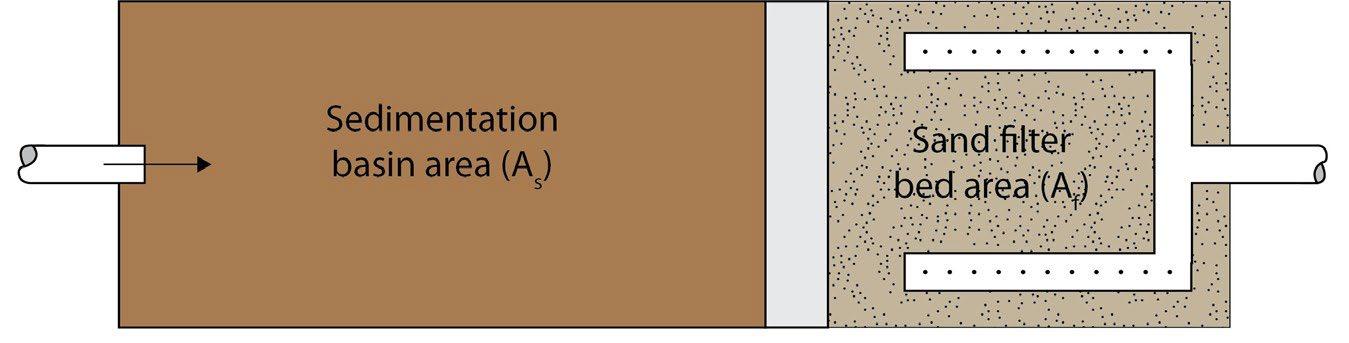
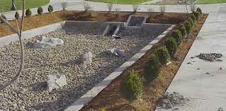
Figure
Examples of Surface Sand Filters
Left: Schematic of a surface sand’s filter basic components (Source: GDOT Drainage Manual, 2023); Right: Sand filter bed of a surface sand filter (Source: NCDEQ Stormwater BMP Manual).
Northeast Tennessee Water Quality SCM Manual
Underground Sand Filter – The underground sand filter (also known as the DC filter) is primarily intended for extremely space limited and highly dense areas. Due to their location below the surface, underground sand filters have a high maintenance burden and should only be used where properly trained inspection and maintenance staff can be ensured. In an underground sand filter, stormwater is conveyed to the sand filter via the stormwater conveyance system. The filter device typically has three chambers (see Figure 5.9.2.2). The initial chamber is a sedimentation (pretreatment) chamber that services as a temporary wet pool to capture heavy sediment and trash. It is connected to the filter bed chamber by a submerged wall that prevents the passage of oil and trash. The filter bed is 18 to 24 inches deep and may have a protective screen of gravel or permeable geotextile to limit clogging. By gravity, filtered water enters the underdrain, which discharges to the third chamber and the outlet. Flows beyond the filter capacity are diverted through an overflow weir.
Underground sand filters can be purchased, fully manufactured with all components, from manufacturers of drainage infrastructure and manufactured treatment devices. Thus, limited design specifications are provided for this SCM.
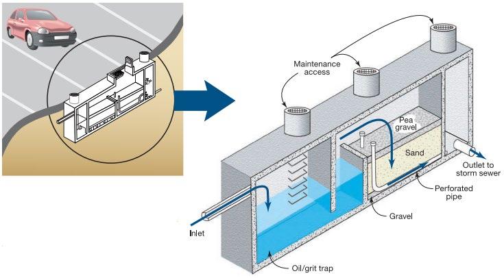

Perimeter Sand Filter – The perimeter sand filter (often called a Delaware sand filter) an enclosed filter system typically constructed just below grade in a vault along the edge(s) of an impervious area such as a parking lot or street . It works in much the same manner as an underground sand filter. The system consists of a sedimentation chamber and a sand bed filter. Stormwater flows directly from impervious surfaces into the structure through a series of inlets (typically grated) located along the top of the control. It is well suited for installation along parking areas. Figure 5.9.2.3 presents a schematic and real example of a perimeter sand filter.
5.9.2.3 Examples of Perimeter Sand Filters
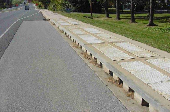


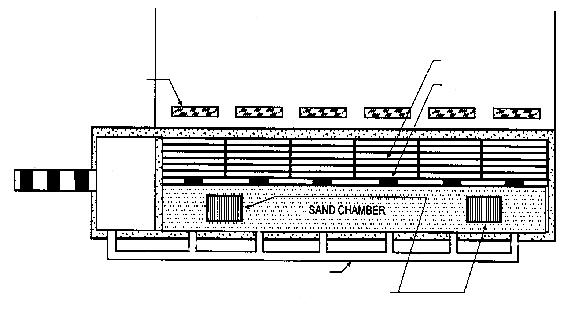


Far left: Perimeter sand filter in the rightof-way (Source: Delaware DOT); Near left: Schematic of basic design elements of a perimeter sand filter (Adapted from stormwatercenter.net)
Figure 5.9.2.2 Examples of Underground Sand Filters
Figure
Left: Drawing of underground sand filter application in a parking lot. Right: Schematic showing the three chambers of an underground sand filter (Adapted from Montgomery County, Maryland)
Northeast Tennessee Water Quality SCM Manual
5.9.3
SCM Suitability
Use Table 5.9.3.1 to determine if a sand filter is suitable for the application being considered.
Table 5.9.3.1 Sand Filter Suitability Factors (all types)
Factor
Stormwater Quality Treatment
Channel Protection
Suitability
Sand filters designed in keeping with the specifications established herein will satisfy local government stormwater quality treatment standards.
Sand filters sized to manage the entire WQv, as described in Chapter 3 (Standards, Methods, and SCM Selection), will meet the CPv standard without the need for additional design. If the basin cannot retain the entire WQv, then the CPv standard is not met.
Detention Sand filters are generally not suitable for peak discharge (detention) control.
Sand filters can be used to address following common stormwater pollutants1:
Pollutant Treatment
Capability
Treatment of Waste and Other Pollutants
1 Georgia Stormwater Management Manual, Volume 2 Technical Handbook, 2016 Edition.
* Cadmium, Copper, Lead, and Zinc
Sand filters shall not be used to treat the following pollutants:
Construction sediment/waste
Landscape storage or waste
Sewage, pet, and livestock waste
Medical waste
Household & commercial wastes
Hazardous wastes
Gasoline, motor oils, greases, and other petroleum-based products
Fats, oils & grease (from food preparation)
Pesticides, fertilizers, herbicides
Other byproducts and waste materials expected, based on the property’s land use
Privately owned sand filter SCMs are not allowed in the public right-of-way.
General suitability criteria by land-use type are as follows See Chapter 3 (Standards, Methods, and SCM Selection) for more information.
Suitability by Land Use
5.9.4
*These policies do not preclude the use of sand filters on individually owned single family or multi-family residential lots. However, sand filters placed on residential lots will not be considered by the local government as suitable for compliance with local government stormwater management requirements due to the inherent difficulties in oversight and enforcement of long-term protection and maintenance requirements on residential lots
Design Requirements
Design specifications for sand filters are presented in this section, as follows.
Table 5.9.4.1 presents specifications applicable to all three types of sand filters (surface, perimeter, and underground).
Northeast
The specifications in Table 5.9.4.1 are not sufficient for a comprehensive design of an underground sand filter. Thus, beyond the standards in the table, design professionals must work with a drainage supply/infrastructure manufacturer of underground sand filters to ensure proper design
Table 5.9.4.2 presents specifications applicable to surface and perimeter filters only.
The criteria provided in the tables shall be considered minimum standards and specifications for the design of sand filters and their contributing drainage areas
Table 5.9.4.1 Design Specifications for Surface, Perimeter, and Underground Sand Filters
Design Element
SAND FILTER LOCATION
Flow Avoidance
Utility Avoidance
Proximity to Trees
Soils
Controls for
Waste & Other Pollutants
Other constraints
Specification(s)
Sand filters shall not be located where they will receive continuous or dry weather inflows from springs, seeps, sump pumps, wash stations, or other sources.
Sand filters shall not be located above underground dry utility lines (electric, cable, and telephone) and water/wastewater infrastructure.
Design professionals must consult the local utility to determine the horizontal and vertical clearance required between SCMs and dry and wet utility lines.
Avoid locating a surface sand filter within 15 feet of shade trees to avoid continued wet conditions, algal blooms, and odors during dry periods.
Avoid location any type of sand filter where leaf litter and other landscape debris will collect and clog the inlets or filter bed.
Sand filters shall not be used in drainage areas with clay and/or silt soils as clogging and failure of the filter bed can occur if the drainage area is not fully stabilized.
Appropriate controls shall be included in the design of the contributing drainage area to the SCM to address any wastes and other pollutants (see Table 5.9. 3.1 above) that are expected on the property after construction. Use the proposed land use as a guide to determine appropriate controls. Examples of such controls include, but are not limited to, dumpsters, trash cans, covered materials/waste storage areas, covered materials transfer areas, oil and grease waste controls, and pet waste stations.
To avoid rapid clogging and failure of the filter media, the use of sand filters shall be avoided for drainage areas that:
have less than 75% impervious cover; or
are expected to yield high amounts of sediment comprised of clay/silt soils after construction is finished.
SAND FILTER DESIGN
The water quality rainfall depth (P) for determination of WQv is:
P = 2.5 inches, or
Water Quality
Volume (WQv)
Use in a Water Quality Treatment Train
the WQv is the first 75% of the volume of the 1-yr, 24-hr storm.
The design professional can select the volume to use for design from the above two options. Acceptable methods to determine WQv are presented in Chapter 3 (Standards, Methods, and SCM Selection).
If the sand filter cannot manage the entire WQv for its contributing drainage area, it must be placed in a treatment train with another SCM. See treatment train policies and calculations in Chapter 3, Section 3.2.4 for treatment train policies and calculations.
Design Element
Drawdown Time
Specification(s)
The treatment volume (typically this will be the WQv) shall fully discharge from the underdrain collection system within 48 hours.
Outlet Structures Sand filter discharge velocities shall not exceed 5 ft/sec.
Emergency Overflow/Spillway
An emergency or bypass spillway shall be included to safely pass flows that exceed the treatment volume (typically this is the WQv).
An offline configuration is constructed away from the main flow path for the drainage area, avoiding large flood flows. A flow splitter, diversion structure, or other means is used upstream of the sand filter’s inlets to redirect the sand filter’s design volume (typically this will be the WQv) from the main flow path to the SCM while still allowing larger flows to remain in the main flow path.
Offline and Online Design Configuration
Surface and perimeter sand filters: An offline configuration is required
Underground sand filters: An offline configuration is preferred; however, consult the sand filter manufacturer.
Flow regulators (flow splitters, diversion structures, and overflow structures) shall be designed in keeping with Sections 5.16 (Inlets, Energy Dissipation, and Pretreatment Measures) and 5.17 (Overflow Controls).
Underdrain See Section 5.15 (Underdrains & Internal Water Storage) for design specifications
Safety Features
Maintenance Access and Easement
Inlets, access grates and outlets shall be designed and maintained so as not to permit access/entry by unauthorized personnel.
The entire sand filter must be accessible for maintenance by the appropriate equipment
A maintenance easement to (and including) the sand filter must be provided from a public roadway. The easement must be free of permanently affixed obstructions (e.g., trees, pools, fences without gates, permanent signs, etc.) to allow maintenance vehicles and equipment to safely pass.
Design Element
Minimum SCM Setbacks
Contributing Drainage Area
Energy Dissipation
Side Slopes
Minimum Depth to Water Table
Specification(s)
Minimum setbacks, measured form the edge of the sand filter, are as follows:
10 feet from a property line.
100 feet from private water supply wells. If the well is downgradient from a land use with a high pollutant load (hotspot area), then the minimum is 250 feet.
TDEC specified distance per designated category from public water supply wells
50 feet from underground septic systems.
Maximum contributing drainage area:
Surface sand filter: 10 acres
Perimeter sand filter: 2 acres.
Maximum slope of CDA (both sand filter types): 6%
Energy dissipation shall be provided for inflow velocities greater than 5 ft/sec
Exit velocities from sedimentation chambers must less than 5 ft/sec.
Surface sand filters: no restrictions; however, ensure side slopes are stable and the filter bed is safely accessible to maintainers that enter the filter bed.
Perimeter sand filters: use precast or cast-place structures to create a stable, vertical side wall.
Minimum separation distance (bottom of excavation to seasonally high-water table) = 2 feet
Table 5.9.4.2 Design Specifications for Surface and Perimeter Sand Filters
Northeast Tennessee Water Quality SCM Manual
Design Element
Minimum Hydraulic Head
Materials, Sizing, Geometry, and Underdrain
Specification(s)
Soil borings shall be used to determine the seasonally high-water table. See Appendix F (Policies for Soil Infiltration Tests & Soil Borings) for soil boring requirements.
Minimum hydraulic head:
Surface sand filter: 5 feet.
Perimeter sand filter: 2 to 3 feet.
The hydraulic head is the difference in the inflow elevation, including the design ponding depth, to the outflow elevation at the underdrain invert elevation or bottom of SCM at its downstream end.
Surface sand filter: see Section 5.9.5 below.
Perimeter sand filter: see Section 5.9.6 below.
5.9.5 Additional Specifications for Surface Sand Filters
The following specifications pertain only to surface sand filters A general schematic of a surface sand filter is presented in Figure 5.9.5.1.
Structure: The sand filter may be constructed of impermeable materials such as concrete, or through the use of excavations and earthen embankments. Inlet and outlet structures shall be located at opposite ends of the chamber.
System sizing: The entire sand filter system, including the sedimentation chamber, must be designed to temporarily hold at least 75% of the treatment volume (typically this will be the WQv) prior to filtration. Figure 5.9.5.2 illustrates the distribution of the treatment volume among the various components of the surface sand filter
Sedimentation chamber sizing: The sedimentation chamber must:
hold at least 25% of the treatment volume (typically this will be the WQv), and
have a length-to-width ratio of at least 2:1.
Filter (sand) bed sizing and composition:
Size the filter bed based on the principles of Darcy’s Law (i.e., the flow rate is proportional to the hydraulic gradient and the hydraulic conductivity). Use 3.5 ft/day for the coefficient of permeability (k) for sand. See Step 4 of the design procedure in Section 5.9.7.
The filter bed is comprised of an 18 inch layer of clean washed medium aggregate concrete sand (ASTM C-33) on top of the underdrain (see Figure 5.9.5.3).
Place a permeable filter fabric/geotextile between the sand bed layer and underdrain layer to prevent clogging of the underdrain.
Optional. If the sand bed will be vegetated, place a layer of permeable filter fabric/geotextile above the sand bed. A 3 to 4 inch layer of topsoil layered on top of the fabric. See also vegetative cover requirements below.
Excavation liner: Sand filters constructed of earthen walls/embankments, line the bottom and side slopes of the excavation with filter fabric before installation of the underdrain and filter media to prevent migration of the in-situ soil into the sand filter layers. If the possibility of sinkhole formation is a concern, use an impermeable liner.
Underdrain Design: See Section 5.15 (Underdrain & Internal Water Storage) and specifications below. The bullets below shall be used in place of specifications for the stone jacket and underdrain slope provided in Section 5.15
Stone underdrain jacket: The perforated pipe underdrain shall be embedded in an 8 inch gravel jacket of cleanwashed No. 1 stone aggregate (1.5 inches to 3.5 inches in diameter, with a void space of about 40%). Aggregate contaminated with soil shall not be used.
Slope: The underdrain shall have a minimum grade of 1/8 inch per foot (1% slope).
Vegetative cover: The filter bed of earthen surface sand filters may be covered with a 3 to 4 inch layer of topsoil and vegetative cover, overlaying a filter fabric/permeable geotextile above the sand bed. Typically, the cover is turf grass, but can also be any non-woody ground cover that will not damage the filter bed. Plants should be selected carefully to ensure no tap roots will penetrate the filter fabric located between the topsoil layer and filter bed (sand).
5.9.5.1

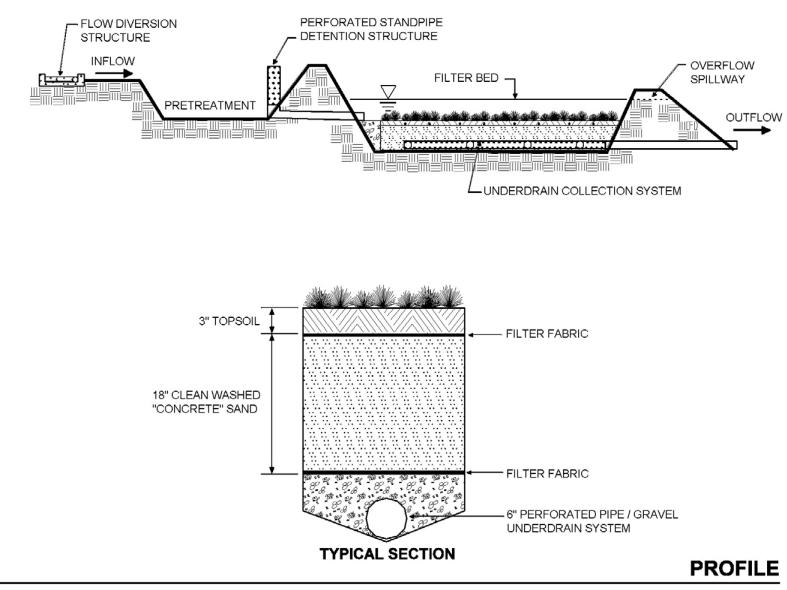
Figure
Schematic of Surface Sand Filter (Source: ARC, 2016)
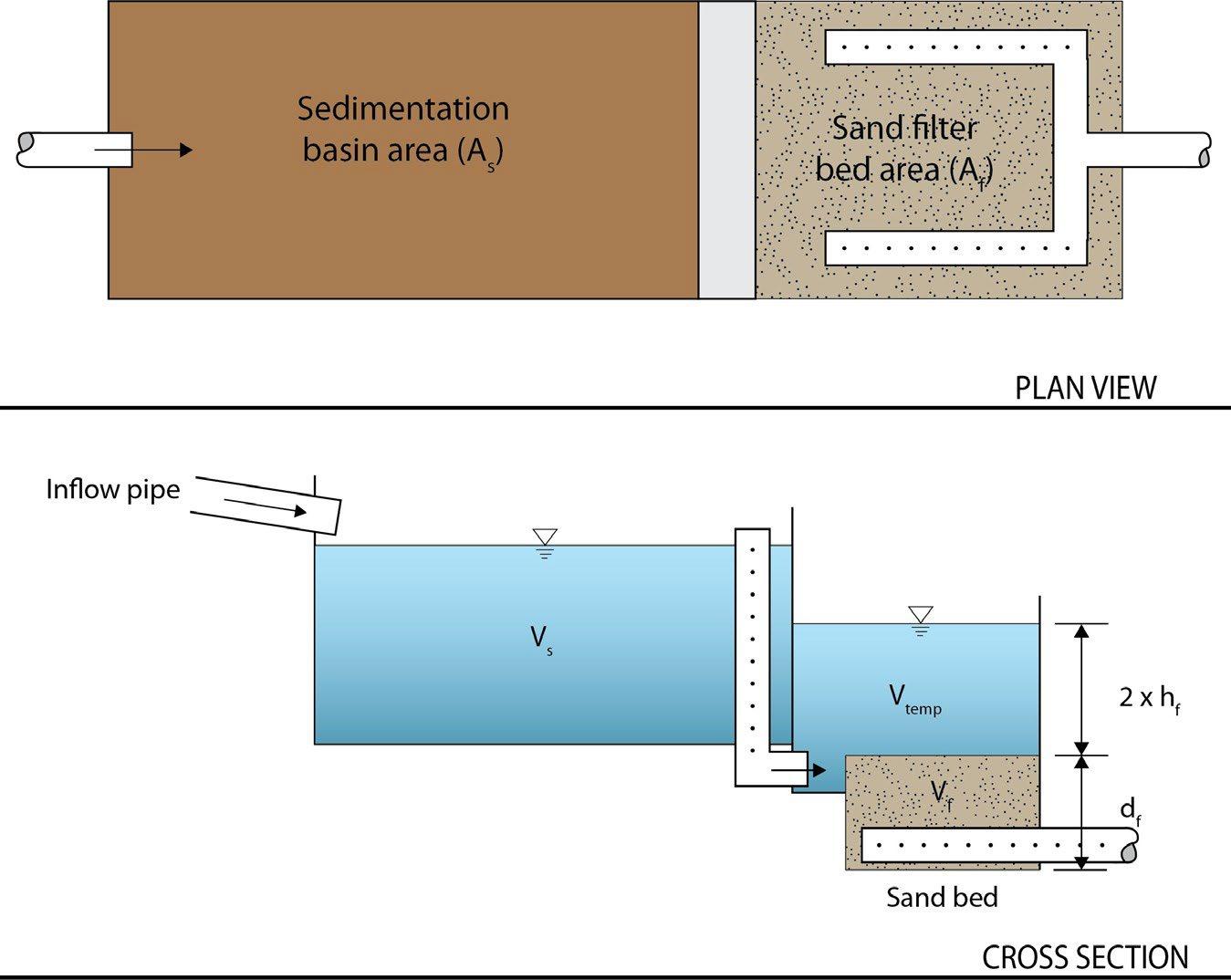
Source for both figures: GDOT Drainage Manual, 2014
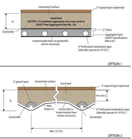
Variables depicted in Figures 5.9.5.2 and 5.9.5.3 are as follows:
As = the surface area of the sedimentation basin
Af = surface area of the filter media
Vs = volume within the sedimentation basin
Vtemp = temporary volume stored above the filter bed
Vf = volume within the voids in the filter bed
hf = average height of water above the filter media
df = depth of filter media (minimum 18 inches)
Figure 5.9.5.2 Surface Sand Filter Volumes
Figure 5.9.5.3 Surface Sand Filter Cross-Sections
Northeast Tennessee Water Quality
5.9.6 Additional Specifications for Perimeter Sand Filters
The following specifications pertain only to perimeter sand filters.
Structure: See Figure 5.9.6.1. Perimeter sand filters are typically constructed of impermeable materials such as concrete. Inflow enters perpendicular to the length of the sand filter through trench grates over the sedimentation chamber. The trench grates also provide access to the sedimentation chamber for maintenance purposes. Once filtered, the water enters an underdrain pipe located throughout the length of the filter bed chamber until the outflow point located at the downstream end of the filter.
5.9.6.1 Concrete Perimeter Sand Filter
Source: NCDEQ Stormwater Design Manual
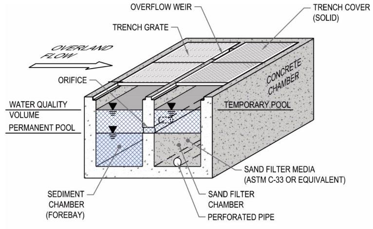
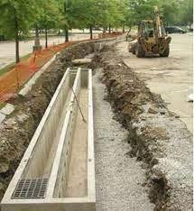
Source: MA (DEP, 2008)
System sizing: The entire sand filter system, including the sedimentation chamber, must be designed to temporarily hold at least 75% of the treatment volume (typically this will be the WQv) prior to filtration. Figure 5.9.6.2 illustrates the distribution of the treatment volume among the various components of the surface sand filter.
Sedimentation chamber sizing: The sedimentation chamber shall be sized to at least 50% of the computed WQv.
Filter (sand) bed sizing and composition:
Size the filter bed based on the principles of Darcy’s Law (i.e., the flow rate is proportional to the hydraulic gradient and the hydraulic conductivity). Use 3.5 ft/day for the coefficient of permeability (k) for sand. See Step 4 of the design procedure in Section 5.9.7
The filter bed is comprised of a 12 to 18 inch layer of clean washed medium aggregate concrete sand (ASTM C-33) on top of the underdrain (see Figure 5.9.6.2).
Place a permeable filter fabric/geotextile between the sand bed layer and underdrain layer to prevent clogging of the underdrain.
Access to the filter bed shall be provided through solid trench covers placed along the length of the filter bed chamber. Covers shall be sufficient in number and size to allow unimpeded access to the entire length, width, and depth of the filter bed for maintenance and repair. Covers may need to be secured to prevent tampering and vandalism.
Underdrain Design: See Section 5.15 (Underdrain & Internal Water Storage) and specifications below. The bullets below shall be used in place of specifications for the stone jacket and underdrain slope provided in Section 5.15 (Underdrain & Internal Water Storage).
Figure
Northeast Tennessee Water Quality SCM
Gravel jacket: The perforated pipe is embedded in an 8 inch gravel jacket of clean-washed No. 1 stone aggregate (1.5 inches to 3.5 inches in diameter, with a void space of about 40%). Aggregate contaminated with soil shall not be used.
Slope: The underdrain shall have a minimum grade of 1/8 inch per foot (1% slope).
Figure 5.9.6.2 Perimeter Sand Filter Dimensions and Volumes (Source: GDOT Drainage Manual, 2023)
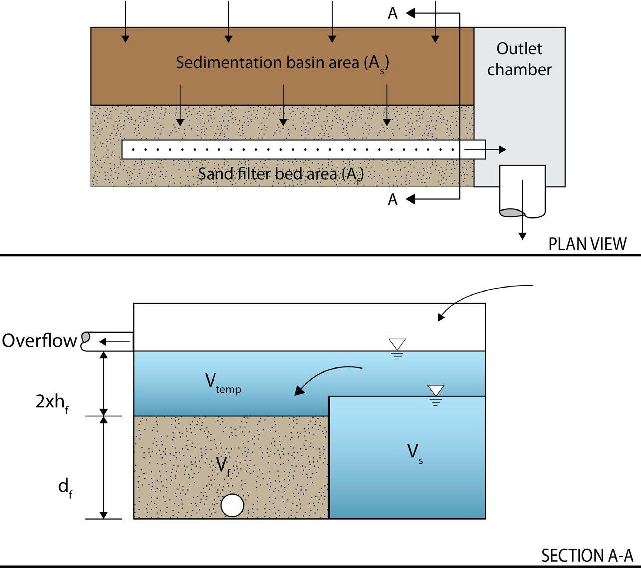
5.9.7 Design Procedure
Table 5.9 7.1 provides the design procedure for sand filters
Table 5.9.7.1 Design Procedure
Step Design Activity
Evaluate sand filter feasibility.
As = the surface area of the sedimentation basin
Af = surface area of the filter media
hf = average height of water above the filter media
df = depth of filter media
Vtemp = temporary volume stored above the filter bed
Vf = volume within the voids in the filter bed
Vs = wet pool volume within the sedimentation basin
Step 1
Use the specifications in Table 5.9.4.1 to determine if a sand filter is feasible for the selected location on the land development site. Consider especially whether it is appropriate for the proposed development based on the intended land use of the property, the maintenance burden, and assumptions or knowledge of how the property owner(s) will care for the sand filter after construction (e.g., self-maintenance, property/facilities management maintenance, landscape contractor). If possible, include the property owner(s) in SCM selection since they will be responsible for maintenance
If a sand filter is determined to be feasible and appropriate for the proposed development, determine which type will be used and create a rough layout of its dimensions, taking into consideration existing trees, utility lines, and other obstructions to ascertain if it will fit into the desired space, given its general design requirements.
Northeast
Step
Step 2
Step 3
Step 4
Step 5
Design Activity
Calculate the design storage volume (DSv) for the contributing drainage area.
Typically, the DSv = WQv, unless the sand filter cannot manage the entire WQv or will be used to control a volume larger than the WQv.
Use one of the calculation methods explained in Chapter 3 Section 3.2.3 (Determining the WQv) to calculate WQv.
Determine the water quality peak discharge (Qwq) and head, then size the diversion structure for flows larger than the WQv.
See Chapter 3, Section 3.2.5 (Calculating the Water Quality Peak Discharge) for determination of Qwq
The overflow elevation is typically set for a maximum design storm, up to the 25-year, 24-hour storm event. Consult the local government to determine the appropriate design storm.
The graphic (below) and associated text provides an example of flow diversion structure design.
Size the orifice to the sedimentation chamber (the low flow orifice) using the orifice equation: ���� =��������������������������������(2���� ℎ) where:
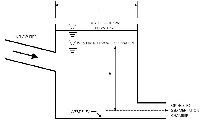
Diagram Source: stormwatercener.net
Size the filter (sand) bed chamber.
where:
Af = surface area of the ponding area (ft2)
DSv = design storage volume (typically this will be the WQv) (ft3)
df = planting media depth (ft)
k = coefficient of permeability of planting media (ft/day) (use 3.5 ft/day for sand)
hf = average height of water ponding above filter bed (ft)
tf = design drain time (days) (two days is the recommended maximum)
Size the sedimentation chamber.
Surface sand filter: Size to at least 25% of the computed WQv and have a length-to-width ratio of 2:1.
Perimeter sand filter: Size to at least 50% of the computer WQv.
The same approach (the Camp-Hazen equation) is used to compute the required surface area for both types of sand filters.
Step Design Activity
where:
As = surface area of the sedimentation chamber (ft2)
QO = rate of outflow from sedimentation chamber = WQv over a 24-hour period
w = Particle settling velocity (ft/sec) (use 0.0033 ft/sec) 1
E’ = sediment trapping efficiency (use 2.30)
The equation reduces to:
Step 6
Step 7
Step 7a
Compute the minimum volume of the entire sand filter (Vmin), including both the sedimentation chamber and filter bed chamber.
Compute storage volumes for entire system and the sedimentation orifice size. ���������������� =
For a SURFACE SAND FILTER (see Figures 5.9.5.2 and 5.9.5.3 for variable definitions).
(1) Compute Vf = water volume within filter bed/gravel/pipe = Af * df * n; where n = porosity =0.4
(2) Compute Vf-temp = temporary storage volume above the filter bed = 2 * hf * Af
(3) Compute Vs = volume within sediment chamber = Vmin - Vf - Vf-temp
(4) Compute hs = height in sedimentation chamber = Vs/As
(5) Ensure hs and hf fit available head and other dimensions still fit. Change as necessary in design iterations until all site dimensions fit.
(6) Size orifice from sediment chamber to filter chamber to release Vs within 24-hours at average release rate with 0.5 hs as average head.
(7) Design outlet structure with perforations allowing for a safety factor of 10 times the orifice capacity.
(8) Size distribution chamber to spread flow over filtration media – level spreader weir or orifices.
For a PERIMETER SAND FILTER (see Figure 5.9.6.2 for variable definitions)
(1) Compute Vf = water volume within filter bed/gravel/pipe = Af * df * n where: Af = surface area of filter bed (ft2)
df = filter bed depth (1.5 ft)
n = porosity = 0.4
7b
Step 8
Step 9
(2) Compute Vw = wet pool storage volume As * 2 feet minimum
(3) Compute Vf-temp = temporary storage volume = Vmin – (Vf + Vw)
(4) Compute htemp = temporary storage height = Vf-temp / (Af + As)
(5) Ensure htemp > 2 * hf, otherwise decrease hf and re-compute. Ensure dimensions fit available head and area. Change as necessary in design iterations until all site dimensions fit.
(6) Size distribution slots from sediment chamber to filter bed chamber.
Design inlets, pretreatment facilities, underdrain, and outlet structures.
See Table 5.9 4.2 and Sections 5.9.5 and 5.9.6 for more specifications
Computer the overflow weir sizes.
For a SURFACE SAND FILTER:
1 Shaver and Baldwin, 1991
Step Design Activity
(1) Size overflow weir at elevation hs in sedimentation chamber (above perforated standpipe) to handle a surcharge of flow through the sand filter system from the 25-year storm.
(2) Plan inlet protection for overflow from sedimentation chamber and size overflow weir at elevation hf in filtration chamber (above the perforated standpipe) to handle a surcharge of flow through filter system from the 25-year storm.
For a PERIMETER SAND FILTER: Size the overflow weir at the end of the sedimentation chamber to handle excess inflow, set at the WQv elevation.
Design the vegetation (if desired for surface sand filters only) and protection measures.
Step 10
Vegetative cover requirements are addressed in Section 5.9.5
Use guidance found in Section 5.9.8 (below) to design protection measures.
5.9.8 Protection Design Guidance
SCMs designed for stormwater quality purposes must be maintained in keeping with the approved SCM design for the life of the land development 2 Design professionals can assist property owners with this requirement by including protective features in and around SCMs to limit the potential for damage by external factors. Often, the landscape and impervious features around an SCM can be tailored to its specific needs, and therefore used to protect its critical components. For surface sand filters, protection is important for the filter bed and other exposed components, to prevent damage by persons or vehicles that may inadvertently enter the filter bed. Protection methods that work well are listed in Table 5.9.8.1
Table 5.9.8.1 Sand Filter Protection Measures*
Natural fencing such as vegetation borders/screens (woody/prickly shrubs or tall grass)
Driveways, sidewalks, or walkways around the SCM
Fencing, curbs, curb blocks
Hardscaping, such as block walls, boulders, cobbles
Educational or directive (e.g., no pets, no entry) signs
Pet waste stations and trash cans near the SCM
* The list presented in the table is not exhaustive. There may be other possible protection measures.
5.9.9 Site Preparation, Land Disturbance, and Installation Requirements
The information in Table 5.9 9.1 provides a typical construction sequence to properly install sand filters. These steps may be modified to reflect different applications or site conditions. Installation practices shall be shown in the EPSC and WQMP plans, as appropriate for the proposed land development.
2 Tennessee Rule 0400-40-10-.04
Table 5.9.9.1 Installation Steps
Step
Step 1
Step 2
Step 3
Step 4
Step 5
Step 6
Requirement
The installation site shall be checked for existing utilities prior to construction.
Sand filters can quickly become clogged if they receive sediment as a result of construction. Thus, sequence site construction so the sand filter is installed only after the area draining to it has been fully and permanently stabilized.
If this is infeasible, block the inlet(s) to the sand filter to entirely prevent inflows of stormwater and cover the filter bed (if exposed) to avoid damage during construction. Install additional erosion prevention and sediment control (EPSC) measures as necessary. For surface sand filters, consider installing temporary signage and high visibility fencing to alert onsite construction staff to the SCM’s presence.
Supervision during construction is required to ensure the sand filter is constructed/installed in accordance with the approved EPSC and WQMP plans. The design professional or a designee under their supervision must inspect the sand filter at critical stages of construction, such as underdrain installation and final inspection. This ensures that the contractor’s interpretation of the plan is consistent with the design professional’s intentions and allows the design professional to certify (in the as-built plan) that the sand filter is built in keeping with the permitted plan.
Construction sites can have many different contractors responsible for different portions of the site or aspects of construction. Therefore, subtle differences in site grading, drainage, and paving elevations from those identified in the design, or relative to different areas/aspects of construction, can affect the hydraulics of the proposed sand filter. The following practices should be done prior to construction to ensure the approved design is still valid:
During the preconstruction meeting, review and confirm that the actual boundaries of the sand filter’s contributing drainage area and inlet elevations conform with the approved design.
Any changes that result from the preconstruction meeting must be shown as a revision to the WQMP and resubmitted to the local government for approval. This includes changes to material certifications for aggregate, media, and liners if not approved prior to the preconstruction meeting.
Install protection and EPSC measures so that construction site stormwater is directed away from the sand filter area.
Special protection measures, such as erosion control fabrics, may be necessary to protect vulnerable side slopes from erosion during the construction.
Excavate the sand filter to its appropriate design depth and dimensions, providing appropriate shoring and sheeting for deep excavations.
If the drainage area to the filter is not fully stabilized, it may be appropriate to excavate the sedimentation chamber first, then seal it to trap sediments prior to installation of the main treatment area.
During and after excavation of the sand filter, all excavated materials shall be placed downstream, away from the sand filter, to prevent redeposit of the material during runoff events.
Confirm and document invert elevations and dimensions for all structures such as vaults and pipes prior to Step 5
Install structures such as inlet boxes, reinforced concrete boxes, inlet controls, and outlet controls according to approved WQMP.
For earthen surface sand filters, place liner layer on bottom and sides ensuring continuous contact with subgrade. Ensure adequate overlap of 16 inches.
For sand filters constructed of concrete or other hard materials (surface and perimeter), place pre-cast vault or perform form work, reinforcement, and concrete work in conformance with project specifications.
Step Requirement
Step 7
Step 8
Step 9
Step 10
Place underdrain gravel jacket and set the underdrain according to plans.
Place geotextile above underdrain.
Secure the geotextile at least 4 feet outside filter bed.
Place sand layer in 6 to 8 inch lifts within structure or excavated area, over the underdrain and storage stone and cover with debris screen, stone filter layer, or non-woven fabric.
Backfill to finished sand grade. Ensure backfill is properly compacted in accordance with specifications. Ensure backfill process does not disrupt pipe placement and configuration.
Install any remaining structures that could not be placed in Step 5, such as inlet boxes, reinforced concrete boxes, inlet controls, and outlet controls according to approved WQMP.
For surface sand filters that will have other cover (e.g., river cobbles, pea gravel), place the surface cover. For surface sand filters with vegetative cover:
Step 11
Install filter fabric/geotextile on sand layer, with at least 16 inches of overlap at seams and at least 4feet of extension beyond filter bed.
Install temporary irrigation measures, if needed, to ensure plants will be watered during the remainder of site construction
Install plants as shown in the approved WQMP.
Step 12
Step 13
EPSC measures can be removed from the inlets once the sand filter’s side slopes and contributing drainage area are fully and permanently stabilized. However, if the area draining to the sand filter includes newly installed asphalt, the erosion/sediment control devices in place to block the inlets should remain in place for at least three storm events after asphalt installation. A substantial amount of fine particles and grit are discharged from newly installed asphalt during the first several storms that produce runoff after installation.
Maintenance will be required to remove the particles and grit if erosion/sediment control devices are removed too early.
Maintain the sand filter in keeping with Section 5.9.10 below.
Prepare the Record Drawing and submit to the local government for review and approval with the engineer’s as-built certification before a final or temporary Certificate of Occupancy can be obtained.
Advise the landowner (i.e., the person(s) taking ownership of the property immediately after its development) of the presence of the sand filter and provide them with a copy of the property’s Record Drawing and SCM maintenance plan. The plan must clearly show the location of the sand filter on the property and list the activities (and their frequencies) necessary for its proper maintenance.
5.9.10 SCM Maintenance on an Active Construction Site
SCM maintenance is regulated by local government ordinance from the moment they are installed. As well, SCMs must pass a final inspection prior to construction termination. This inspection will be performed to ensure they are constructed in accordance with the approved WQMP, undamaged, and free of sediment and debris. Thus, SCM maintenance is good practice to ensure construction termination goes smoothly. Relevant policies are as follows:
The property owner is responsible for SCM maintenance. If the property is still an active construction site, these responsibilities may fall to the land disturbance permittee until the project receives final approval from the local government and/or a Certificate of Occupancy.
Property owners may have others, such as a site contractor or landscaping company, maintain the sand filter on their behalf. However, the local government will hold the property owner responsible for ensuring it is maintained in proper operating condition (i.e., as designed and constructed) regardless of who performs maintenance activities.
Northeast Tennessee Water Quality SCM Manual
Maintenance activities, which include ensuring proper operation of the SCM as designed and required SCM inspections, must begin immediately following installation of the sand filter.
Maintenance activities shall be performed in keeping with the Northeast Tennessee SCM Inspection and Maintenance Manual. Additional guidance on maintenance of newly installed sand filters located on active construction sites is provided in Table 5.9.10.1.
Table 5.9.10.1 Maintenance Activities for Newly Installed Sand Filters
Contributing Drainage Area
Sand Filter
Keep the contributing drainage area clean. Sweep trash, debris, and sediment frequently so that it does not wash in the basin during a rain event.
The area should be fully stabilized before installation of the SCM. If it is not, prevent inflows to the sand filter as described previously. Stabilize the area as soon as possible to prevent the discharge of sediment to the SCM
Cover stockpiles of construction and landscape materials to prevent their exposure to rainfall.
For surface sand filters that have vegetative cover, ensure SCM plants are watered and growing as expected.
Ensure the filter bed remains free of accumulated sediment, landscape debris, and trash
Ensure vehicles, equipment, and people are not allowed in the sand filter. Evidence of unwanted entry may look like tire tracks or footprints; sand or stone displacement, or damage to components; immediately determine and eliminate the cause and repair the area. Consider installing temporary fencing.
Visually observe sand filter function after rain events; there should be no standing water in 48 after a storm event, depending on the frequency of rainfall . If long-standing water is observed:
Education
Inspect underdrain via the observation wells, looking for standing water indicative of a blockage or damage; make repairs if needed.
If underdrain/outlet blockages and damage can be ruled out, then the filter bed may be clogged. This repair may require filter media removal, underdrain cleaning, and reinstallation of the filter bed chamber; consult the design engineer.
Alert onsite subcontractors to the SCM and the following requirements:
No muddy vehicles or equipment in the drainage area to the sand filter
No stockpiling of material in the filter bed and no exposed stockpiles in the filter’s drainage area.
Block inlets prior to asphalt placement in the drainage area.
Remove sediment, trash, debris, and empty trash cans frequently.
Advise landscaping subcontractors on proper protection and maintenance of the sand filter, especially no dumping of lawn clippings or landscape debris in the filter area and to cover materials stockpiles.
5.9.11 References
ARC. Georgia Stormwater Management Manual Volume 2 Technical Handbook, 2016 Edition. Atlanta Regional Commission, 2016
Georgia Department of Transportation. Drainage Design for Highways. Revision 3.3. March 31, 2023.
Knox County, TN. Stormwater Management Manual. Volume 2. January 2018.
Montgomery County, Maryland, Department of Environmental Protection. Structural Maintenance: Underground Sand Filters. Stormwater Facility Maintenance Program. 2013 Area or Component
North Carolina Department of Environmental Quality. Stormwater Design Manual. C-6. Sand Filter. Revised November 7, 2018.
Shaver, E. and R. Baldwin. 1991. Sand Filter Design for Water Quality Treatment. Delaware Department of Natural Resources and Environmental Control. Dover, DE.
Stormwatercenter.net Performance Criteria: Stormwater Filtering Systems. Online. Accessed February 2024. https://www.stormwatercenter.net/Manual_Builder/Performance%20Criteria/Filtering%20Systems.htm
5.10 Stormwater Wetland
design specification
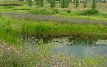
Water Quality Volume (WQv) Rainfall Group 3 Design
P = 2.5 inches or the first 75% of the volume from the 1-yr, 24-hr storm, whichever is less OTHER SCM ATTRIBUTES
Channel Protection Volume (CPv) Yes
Detention / Retention Control Yes
Small
SCM Group: 3
Overview
Stormwater wetlands are above-ground stormwater storage facilities that provide water quantity (i.e., flood) control through temporary detention of stormwater and stormwater quality control by extending the storage time of the WQv. Stormwater is treated through natural filtration, plant uptake, and settling during extended detention in the wetland before discharging offsite, or to the onsite stormwater conveyance system.
ADVANTAGES/BENEFITS
Provides both stormwater quality and quantity control
Some design variations can serve very large drainage areas
Can provide a park-like amenity and natural wildlife habitat
Relatively low maintenance costs
Ideal for use in flat terrain and in areas with high groundwater
DISADVANTAGES/LIMITATIONS
The wetland itself requires a large land area
A permanent wetland pool must be maintained
Requires strict control of incoming sediment to sustain wetlands
Mosquitos can be problematic
DESIGN CONSIDERATIONS FOR LOCATION, SIZING, & COMPONENTS
Best located in areas with a continuous high-water table or baseflow
Minimum dry weather inflow to outflow path of 2:1 (length:width)
Requires design of a variable pool areas and depths
Sediment forebay required at each inlet
DESIGN CONSIDERATIONS FOR LONG-TERM PROTECTION
Primary concerns are dumping (trash, landscape debris, etc.) and poor plant management (mowing, clearing, etc.) due to landscaper ignorance about the SCM
Consider permanent “no mow zone” or similar signs to alert landscapers to the presence and preservation of the wetland
Maintained vegetated areas and quiet walkways along the wetland border can support its protection as intentional landscape or even a property amenity
DESIGN CONSIDERATIONS FOR LONG-TERM MAINTENANCE
Primary routine maintenance activities will be plant care (e.g., plant replacement, invasive species management) and inlet/outlet cleaning (trash, debris, plant matter, etc.)
Consider permanent signs to dissuade entry, dumping, and use of SCM as a pet relief area if located near a pedestrian area
Provide trash cans and pet waste stations in the drainage area
Northeast Tennessee Water Quality
5.10.1. General Description
Stormwater wetlands (sometimes also called constructed wetlands) are stormwater control measures (SCMs) designed and constructed as shallow marsh systems. They are typically designed to remove pollutants from stormwater and provide flood control by reducing peak discharges for large storms They are among the most effective stormwater practices in terms of pollutant removal. Stormwater entering the wetland displaces a portion of the retained pool volume as it flows slowly through the wetland. During this time multiple pollutant removal processes occur including filtration of water through plant leaves, gravitational settling in pool areas, and uptake of nutrients and other pollutants by plants, soil, and microorganisms A multi-stage outlet structure at the downstream end of the wetland provides peak flow control
Stormwater wetlands differ from natural wetland systems in that they are designed specifically for the purpose of treating stormwater. They also often have less biodiversity than natural wetlands both in terms of plant and animal life. However, they are similar to natural wetlands in that they require a continuous base flow or a high-water table to support wetland vegetation and function
5.10.2. Design Configurations
Stormwater wetlands can be designed in either a Level 1 or Level 2 configuration, as follows.
Level 1 designs are “full control” designs. They provide for WQv, channel protection volume (CPv) control, and flood control (post-development to pre-development peak discharge matching) for large storm events regulated via a multistage outlet riser and emergency spillway.
Level 2 designs are “WQv only” designs. They address the WQv, but cannot provide extended detention, thus requiring another SCM, such as a wet detention basin, for CPv and flood control. Stormwater wetlands with Level 2 designs are suitable for a parallel installation to a wet detention basin. The latter facility can help maintain the permanent pool within the wetland.
As well, there are several types of stormwater wetland s, each differing in the relative number and volume of dry storage areas and shallow water and deep-water pools The wetland types are described in the following paragraphs and shown in Figure 5.10.2.1 Schematics of each wetland type are shown at the end of this design specification (Section 5.10.14).
Extended Detention (ED) Shallow Wetland (Level 1 – full control) – The extended detention (ED) shallow wetland design is the same as the shallow wetland; however, part of the WQv is provided as extended detention above the surface of the marsh and released over a period of 24 hours. This design can treat a greater volume of stormwater in a smaller space than the shallow wetland design. Plants that can tolerate both wet and dry periods need to be specified in the ED zone.
Basin/Shallow Wetland System (Level 1 – full control) – The basin/wetland system has two separate cells: a wet basin and a shallow marsh. The wet basin traps sediments and reduces velocities prior to stormwater entry into the wetland. Additional treatment is then provided in the remainder of the wetland. A basin/wetland system requires less land than the shallow wetland and ED shallow wetland systems.
Shallow Wetland (Level 2 – WQv only) – In a shallow wetland, most of the water quality volume (WQv) is in the relatively shallow high marsh or low marsh depths. The only deep portions are the forebay at the wetland inlet and the micropool at the outlet. A disadvantage of this design is that a relatively large amount of land is typically needed to store the WQv since the pool is very shallow.
Pocket Wetland (Level 2 – WQv only) – The stormwater wetland design variations described above serve a minimum drainage area of 10 to 25-acres, depending on source water availability. In contrast, a pocket wetland is intended for smaller drainage areas of 5 to 10 acres. However, it often requires excavation down to the water table for a reliable water source to support the wetland system. Pocket wetlands are smaller, more compact wetland systems intended for use where drainage area sizes will not support a larger wetland system.
Submerged gravel wetland – Due to their significant difference from the stormwater wetland design variations described above, design specifications for submerged gravel wetlands are addressed in Section 5.11 (Submerged Gravel Wetland).
Figure 5.10.2.1 Examples of Stormwater Wetland Variations
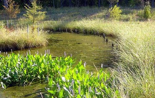
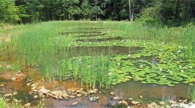
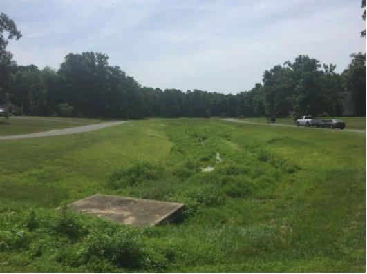
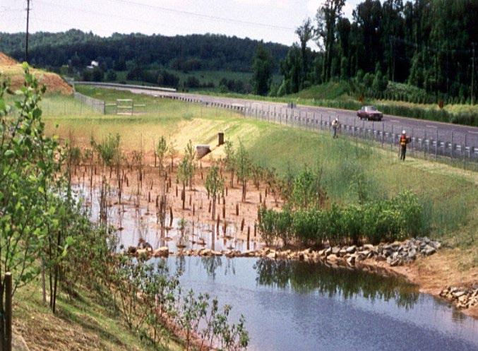
5.10.3. SCM Suitability
Use Table 5.10.3.1 to determine if a stormwater wetland is suitable for the application being considered.
Table 5.10.3.1 Stormwater Wetland Suitability Factors
Factor Suitability
Hydrologic Feasibility
Stormwater Quality Treatment
IMPORTANT! A continuous base flow or high-water table is required to support wetland vegetation. See Section 5.10.5 (Hydrologic Requirements & Design Options) below for more information.
Level 1 and Level 2 stormwater wetlands designed in keeping with the specifications established herein will satisfy local government water quality treatment standards.
Channel Protection
Level 1 stormwater wetlands sized to manage the entire WQv, as described in Chapter 3 (Standards, Methods, and SCM Selection), will meet the CPv standard without the need for additional design. If the basin cannot retain the entire WQv, then the CPv standard is not met.
Level 2 stormwater wetlands do not provide extended detention and therefore cannot meet the CPv standard.
Detention
Level 1 stormwater wetlands can be designed to satisfy local government peak discharge (flood) control requirements.
Level 2 stormwater wetlands do not provide peak discharge control.
Top left: Shallow wetland (Maryland Department of Transportation); Top right: Extended detention shallow wetland (Maryland Department of Environment); Bottom right: Basin/wetland system ( Connecticut Stormwater Quality Manual); Bottom left: Pocket wetland (Athens-Clarke County, GA)
Northeast Tennessee Water Quality SCM Manual
Factor Suitability
Level 1 wetland systems designed in keeping with the specifications established herein can address the following common stormwater pollutants:
Pollutant Treatment
Capability (Level 1 Designs)
Pollutant Treatment
Capability (Level 2 Designs)
1 – If designed for the WQv specified in Tennessee Department of Environment and Conservation Rule 0400-40-10-.04
2 – Georgia Stormwater Management Manual, Volume 2 Technical Handbook, 2016 Edition.
3 – Cadmium, Copper, Lead, and Zinc
Level 2 wetland systems designed in keeping with the specifications established herein can address following common stormwater pollutants:
Treatment of Waste and Other Pollutants
1 – If designed for the WQv specified in Tennessee Department of Environment and Conservation Rule 0400-40-10-.04
2 – Georgia Stormwater Management Manual, Volume 2 Technical Handbook, 2016 Edition.
3 – Cadmium, Copper, Lead, and Zinc
Stormwater wetlands shall not be used to treat the following pollutants:
Construction sediment/waste
Landscape storage or waste
Sewage, pet, and livestock waste
Medical waste
Household & commercial wastes
Hazardous wastes
Gasoline, motor oils, greases, and other petroleum-based products
Fats, oils & grease (from food preparation)
Pesticides, fertilizers, herbicides
Other byproducts and waste materials expected, based on the property’s land use
Privately owned detention basins are not allowed in the public right-of-way.
General suitability criteria by land-use type are as follows. See Chapter 3 (Standards, Methods, and SCM Selection) for more information.
Suitability by Land Use
*These policies do not preclude the use of stormwater wetlands on individually owned single family or multi-family residential lots. However, wetlands placed on residential lots will not be considered by the local government as suitable for compliance with local government stormwater management requirements due to the inherent difficulties in oversight and enforcement of long -term protection and maintenance requirements on residential lots
5.10.4. SCM Location Requirements
Location constraints for stormwater wetlands are provided in Table 5.10 4.1
Table 5.10.4.1 Stormwater Wetland Location Requirements
Physical Element
Minimum SCM Setbacks
Requirement
Minimum setbacks for all wetland designs, measured from the edge of the stormwater wetland, are as follows:
10 feet from property lines
Northeast Tennessee Water Quality SCM
Physical Element
Prohibited Locations
Trout Streams
Requirement
100 feet from private water supply wells; if the well is downgradient from a hotspot land use, then the minimum setback is 250 feet.
TDEC specified distance per designated category from public water supply reservoirs
50 feet from underground septic systems
5 miles from airports (due to propensity for waterfowl habitation).
Stormwater wetlands cannot be located within navigable waters of the U.S., including wetlands, without obtaining a Section 404 permit under the Clean Water Act, and any other applicable State permit. In some isolated cases, a wetlands permit may be granted to convert an existing degraded wetland in the context of local watershed restoration efforts.
Stormwater wetlands often intersect the groundwater table. Thus, these SCMs are not suitable for locations:
with an underlying water supply aquifer
where they will receive stormwater discharges from land uses where high level(s) of pollutant(s) are expected (see Treatment of Wastes and Other Pollutants in Table 5.10.3.1 above)
locations where soil contamination is known or suspected.
Stormwater wetlands can have a thermal influence on downstream trout waters. Avoid placement in locations that discharge directly to trout streams.
Utility Avoidance All utilities shall be located outside of the stormwater wetland.
Waterway Avoidance
Stormwater wetlands shall not be located in a stream or any other navigable waters of the United States, including natural (i.e., not constructed) wetlands. Where an appeal or variance of this policy is desired, the property owner must obtain coverage under a Section 404 permit under the Clean Water Act and/or an Aquatic Resource Alteration Permit (ARAP) and provide proof of such coverage with the Water Quality Management Plan.
5.10.5. Hydrologic Requirements & Design Options
A primary cause of stormwater wetland failure is the inability to maintain the permanent pool elevation (PPE) at its design elevation. Poorly draining soil and a frequent high groundwater elevation are critical to PPE support, and therefore stormwater wetland operation and their ultimate success or failure. Thus, knowledge of the seasonal high-water table (SHWT) and in-situ soil permeability are critical to determine the feasibility of a stormwater wetland as a viable SCM.
Soil permeability tests and SWHT determination and infiltration tests shall be performed by either a professional geologist or civil (geotechnical) engineer with an active license in the State of Tennessee.
SOIL PERMEABILITY: Permeable soils are not well-suited for a constructed stormwater wetland without a high-water table. Underlying soils of hydrologic group “C” or “D” should be adequate to maintain wetland conditions. Most group “A” soils and some group “B” soils will require a liner.
Soil permeability must be tested in the proposed stormwater wetland location to ensure that excessive infiltration will not cause the SCM to dry out. If necessary, stormwater wetlands should have a highly compacted subsoil or an impermeable liner to minimize infiltration.
SOIL BORINGS AND CORE INTERPRETATION: Soil borings provide information on the SHWT Table 5.10.5.1 provides soil boring location and depth requirements.
Table 5.10.5.1 Soil Boring Requirements
Factor Requirement
A minimum of:
one (1) boring within the footprint of the proposed stormwater wetland embankment; and,
Location
Depth
one (1) boring in the vicinity of the proposed outlet structure; and,
one (1) boring for every 20,000 square feet within the proposed wetland area.
Soil borings shall be conducted to a depth of at least 10 feet below the estimated lowest bottom elevation of the stormwater wetland.
Each soil core shall be observed to determine the anticipated SHWT based on:
the date of soil boring with respect to any visual observations of water in the core (or boring)
recent and seasonal rainfall patterns
the presence of hydric soils
redoximorphic features or other indicator of water table variation
and depth to bedrock if encountered.
If mottling showing redoximorphic features is observed, at any season of the year, the SHWT shall be taken as the highest level at which the mottling is observed, except when the water table is observed at a level higher than the level of the redoximorphic depletions or concentrations. Otherwise, use best practices for SWHT determination as appropriate for water table/soil conditions at the location of the wetland. Use the most recent version of the USDA-NRCS reference document titled Field Indicators of Hydric Soils in the United States – A Guide for Identifying and Delineating Hydric Soils for more information on determining whether saturated soils are present
HYDROLOGIC SUPPORT DESIGN OPTIONS. Three options exist for the design of wetlands depending on the depth to groundwater and native soils, as follows:
1. Wetland intersecting groundwater (required configuration for pocket wetlands): If the wetland will intersect a shallow groundwater table, groundwater may be utilized to maintain the PPE at the design elevation. The PPE established for the wetland shall be within 6 inches above or below the SHWT. Based on the results of the water balance calculations [see Chapter 3 (Standards, Methods, and SCM Selection)], an impermeable liner may be required under the deep pools to reduce the likelihood of the pools drying up completely during a time of unusually low groundwater elevation.
2. Wetland above groundwater with low-permeability native soils: If the SHWT is below the proposed wetland elevation and soil testing shows that the native soil beneath the wetland is clay or similar with an infiltration rate of less than 0.01 in/hr, the wetland will hold water and can be designed without an impermeable liner. If, during construction, any areas with more permeable soil types are discovered, an impermeable liner shall be designed and installed for these areas.
3. Wetland above groundwater with highly permeable native soils (allowed only if other SCMs are not feasible for the proposed development): If the native soils above the SHWT are highly permeable soils like loam and sand, installation of an impermeable liner with an infiltration rate of less than 0.01 in/hr is required. The liner can be constructed of clay, other soils that meet the infiltration rate requirement, or an impermeable geomembrane. Location constraints for stormwater wetlands are provided in Table 5.10.4.1.
WATER BALANCE. Once the hydrologic support design option is determined, design professionals are strongly encouraged to perform a water balance calculation BEFORE further design activities are undertaken. The water balance must demonstrate that the stormwater wetland can withstand a 30-day drought at summer evaporation rates without creating
a drawdown that will dry the wetland and damage or destroy the wetland vegetation. See Chapter 3, Section 3.2.8 for more information on water balance calculations.
5.10.6. Components
Figure 5.10.6.1 presents a general schematic cross-section of a stormwater wetland.
Figure 5.10.6.1 General Cross-Section of A Stormwater Wetland

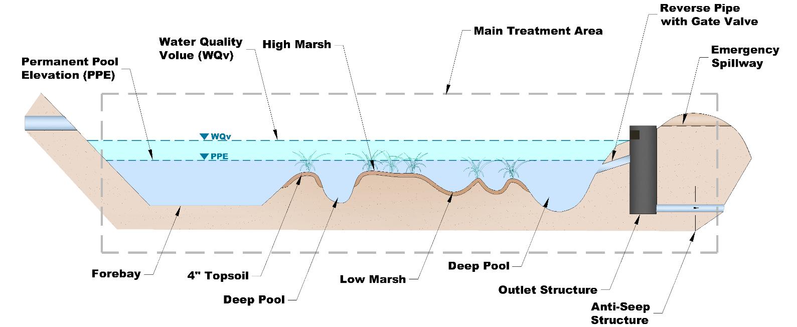
In general, stormwater wetlands consist of seven primary components, described below.
1. Inlet(s): Stormwater enters the wetland via one or more inlets A specific type of inlet is not required. Inlets can be swales, pipes, diverter boxes, areas of sheet flow, or other methods of transporting water to the wetland.
2. Forebay: The forebay is a deep pool that directly follows the inlet and provides two important functions: (1) dissipates stormwater velocity and energy; and (2) collects gross solids and sediment to ease maintenance. The forebay essentially acts as a pretreatment device for the stormwater wetland. The water flows out of the forebay and into the wetland. The entrance to the forebay is deeper than the exit of the forebay. This design will dissipate the energy of the water entering the system and ensure that l arge solids settle out.
3. Deep pools: Deep water cells include the outlet pool and deepwater channels running through the wetland. Very little rooted vegetation exists in these areas because they are always under water, but they may support submerged and floating plants. However, the deep pool at the outlet should not have any vegetation to avoid outlet clogging. Deep pools provide additional pollutant removal and storage volume as well as habitat for aquatic wildlife such as mosquito-eating fish.
4. Low marsh: Low marsh areas are shallow water areas inundated by the permanent pool to a depth of 3 to 6 inches with occasional drying during periods of drought. Low marsh areas provide a constant hydraulic connection between the inlet and outlet structure of the stormwater wetland. The top of low marsh areas represents the top of the permanent pool elevation (PPE). Wetland tolerant, herbaceous plants (i.e., plants with flexible, green stems and few to no woody parts) are recommended for this area because they are more efficient in the pollutant removal process and less likely to encourage mosquito growth.
5. High marsh: High marsh areas support a greater density and diversity of wetland plants (described in the paragraph above), thus providing much of the vegetative pollutant uptake
Inlet
Northeast Tennessee Water Quality SCM
6. Lowland: Lowland areas (not shown in the figure) are located above the permanent pool and are wet only during larger storm events. Rooted plants including woody vegetation can live in this zone to provide shade and nonaquatic wildlife habitat Vegetation must be able to withstand irregular inundation and occasional drought.
7. Upland: Lowland areas (not shown in the figure above) are never wet. They are not a required element of wetland design and can be eliminated if space is a concern. They may serve as an amenity and provide access for maintenance. Some wetlands have upland areas as an island in the center of the wetland.
8. Outlet: For a Level 2 stormwater wetland (WQv only), the outlet consists of a drawdown orifice placed at the top of the shallow water elevation so that stormwater in the shallow land area will be able to slowly discharge from the wetland. For a Level 1 wetland, an outlet riser is designed to discharge the WQv/CPv and flood control events (i.e., providing peak discharge control). An emergency spillway may be included at the top of the outlet riser or can be located on the wetland embankment.
In addition to the above eight components, basin/shallow wetland configurations must include a wet basin located in parallel. Design specifications for the latter SCM are provided in Section 5.14 (Water Quality Basin).
Additional components (not shown) for all stormwater wetland types include a safety bench, and upland areas for maintenance access and a wetland buffer. Upland areas may also serve as amenity areas or even islands in the center of the wetland for waterfowl and upland vegetation
5.10.7. Design Specifications
Design specifications are provided in Tables 5.10.7.1 and 5.10.7.2 and shall be considered minimum standards and specifications for the design of stormwater wetlands and their contributing drainage areas. The schematics of stormwater wetlands provided at the end of this design specification (Section 5.10.14) may also be helpful with wetland design.
Table 5.10.7.1 Design Specifications for the Contributing Drainage Area
Design
Size
Specification(s)
For pocket wetlands: minimum contributing drainage area = 5 acres.
For all other stormwater wetlands: the minimum contributing drainage area is:
25 acres if stormwater is the only source of water for the wetland.
10 acres if groundwater will supply the wetland (i.e., the wetland bottom will intercept the water table).
See also Section 5.10.5 (above) regarding hydrologic support for the wetland.
Slope Maximum slope of contributing drainage area = 8%.
Controls for Waste & Other Pollutants
Appropriate controls shall be included in the design of the contributing drainage area to the SCM to address any wastes and other p ollutants (see Table 5.10 3.1 above) that are expected on the property after construction Use the proposed land use as a guide to determine appropriate controls. Examples of such controls include, but are not limited to, dumpsters, trash cans, covered materials/waste storage areas, covered materials transfer areas, oil and grease waste controls, and pet waste stations
Table 5.10.7.2 Design Specifications for the Stormwater Wetland
Design Element
Water Quality
Volume (WQv)
Specification(s)
The water quality rainfall depth (P) for determination of WQv is P = 2.5 inches, or the WQv is the first 75% of the volume of the 1-yr, 24-hr storm, whichever is less. The design professional can select which volume to use.
Northeast Tennessee Water Quality
Design Element
Use in a Water Quality Treatment Train
Hydrologic Support
Water Balance
Minimum Hydraulic Head
Geometry, Depths, and Storage Volumes
Specification(s)
Acceptable methods to determine WQv are presented in Chapter 3 (Standards, Methods, and SCM Selection)
If the stormwater wetland cannot manage the entire WQv for its contributing drainage area, it must be placed in a treatment train with another SCM. See treatment train policies and calculations in Chapter 3, Section 3.2.4 for treatment train policies and calculations.
A continuous base flow or high-water table is required to support wetland vegetation. See Section 5.10.5 above.
A water balance calculation must demonstrate that the stormwater wetland can withstand a 30day drought at summer evaporation rates without creating a drawdown that will dry the wetland and damage or destroy the wetland vegetation.
See Chapter 3, Section 3.2.8 for more information on water balance calculations.
Minimum elevation difference from wetland inflow to outflow:
Pocket wetland = 2 to 3 feet
All other wetland types = 3 to 5 feet
Stormwater wetlands shall be irregularly shaped with long, sinuous flow paths.
Stormwater wetlands are constructed by excavating the overall wetland basin, building up earthen embankments (dikes), or a combination of the two methods, sufficiently to create the desired number of internal cells In general, Level 1 stormwater wetlands should be divided into at least four internal cells of different elevations: the forebay, a deep pool at the outlet, and two additional cells. This rule of thumb does not extend to Level 2 wetlands.
If multiple cells are used, divider dikes can be used to separate cells and to produce the desired length-to-width ratios. On steep sites, they can be used to terrace cells.
Dikes forming internal cells shall be constructed of soils with adequate fine-granted material to ensure compaction into relatively stable and impervious embankments. Placement of erosion control matting on dike side slopes is acceptable.
Dikes should be high enough to contain the expected volume within each internal cell plus freeboard (at least 1 ft) to accommodate occasional high flows and sediment/litter buildup over time.
Table 5.10.7.3 provides general rules for pool depths and volumes for stormwater wetland subcells.
Table 5.10.7.3 Sub-Cell Depths & Volumes for Various Level 1 and 2 Wetland Zones
1 Designers must account for 4 to 6 inches of topsoil to be placed on in-situ soils.
Finger dikes within the internal cells are used to create the sinuous flow path, further refine the desired length-to-width ratio and minimize short circuiting of water through the wetland. Finger dikes can be constructed of soil, sand berms/bags (anchored by rock at each end), back-filled coir
Northeast
Design Element
Specification(s)
fiber logs, or leaving-in place existing upland areas as forested peninsulas (extending as wedges across 95% of the wetland width).
Table 5.10.7.4 provides additional geometry criteria for Level 1 and Level 2 stormwater wetlands.
Table 5.10.7.4 Sub-Cell Depths & Volumes for Various Level 1 and 2 Wetland Areas
Number of deep pools 2 (forebay and outlet) 3 (forebay, middle, outlet)
Maximum side slopes (H:V) (wetland boundary and dikes) 3:1 (2:1 preferred)
Slope profile 8% across entire site
Normal flow path (length : width) (distance from nearest inlet to the outlet)
Geometry, Depths, and Storage Volumes (continued)
(including topsoil)
Topsoil depth and composition (marsh zones & safety benches)
Safety bench (required for deep pools)
(2:1 preferred)
Generally flat (use several cells if needed with a maximum drop of 1 ft between each)
4 to 6 inches
High organic content loam or sandy loam
Width = 4 to 6 feet
Depth = 1 to 2 feet below the water surface, transitioning to zero width at grade
Minimum Freeboard 1 foot Not required
Extended detention Limit to 1 ft vertically Not allowed
Designs for wetlands that impound more than 30 acre- feet of water may require adherence to the Tennessee Safe Dams Act. Consult the Tennessee Department of Environment and Conservation (TDEC) for more information.
Level 1 (full control) stormwater wetlands:
Routing calculations must demonstrate that the storage volume of the wetland is adequate (not including freeboard) for all design storms. See Chapter 3 (Standards, Methods, and SCM Selection) for more information on storage design requirements.
Level 2 (WQv only) stormwater wetlands:
Micro-topology is important to Level 2 wetland designs. Planting peninsulas are the preferred method, but the following list can be used to enhance micro-topology:
Snags
Inverted root wads Tree peninsulas Coir fiber islands
ADDITIONAL DESIGN TIPS FOR ALL STORMWATER WETLANDS
Internal pools Cobble sand weirs
Stormwater wetland designs should be kept simple as complex technological approaches often invite failure. Tips for stormwater wetland designs are as follows.
Design Element
Forebay
Outlet Structures
Specification(s)
Design the system to use natural energies, such as gravity flow.
Design the wetland with the landscape, not against it. Integrate the design with the natural topography of the site.
Avoid over-engineering the design with rectangular basins, rigid structures and channels, and regular morphology. Rather, mimic natural systems.
Design the system for function, not form. For instance, if initial plantings fail, but the overall function of the wetland, based on initial objectives, is intact, then the system has not failed.
Design for the extremes of weather and climate, not the average. Storms, floods, and droughts are to be expected, so the design must reflect this fact.
Forebays are critical to wetland longevity as they trap sediment and protect the capacity of the internal wetland cells located downstream The following criteria apply to forebay design
A forebay shall be provided for every individual storm drain inlet pipe or open channel conveying stormwater into the wetland from at least 10% of the contributing drainage area.
The forebay is a separate cell and formed by a dike formed by an earthen berm, concrete weir, gabion baskets, or similar.
Required volume = 10% of the WQv of the wetland.
The forebay volume can be considered as part of the WQv, not additional volume of the wetland.
Depth = 4 to 6 feet
When determining forebay geometry, greater depth is preferred over greater width. This allows the forebay to dissipate turbulent inflows without resuspending previously deposited sediment; however, safety concerns and ease of maintenance must be considered when designing sediment forebays.
A safety bench is required around the perimeter of forebay per specifications described for deep pools in the previous row of this table.
The bottom of the forebay may be a hardened surface, such as concrete, asphalt, or grouted riprap, to make sediment removal easier.
A fixed vertical sediment depth marker (metered rod) shall be located in the center of the forebay pool (as measured lengthwise along low-flow water travel path) to measure sediment deposition over time.
Requirements for all stormwater wetlands:
Drawdown of the stormwater wetland’s temporary pool shall be accomplished within 48 to 72 hours from the storm event.
Outlets shall be located within the outlet pool and basin embankment, and shall be designed for easy access, maintenance, and safety.
Outlets, including emergency spillways, shall be designed so that discharges will not cause negative impacts to downstream structures.
Clogs, even of the low-flow orifice, can result in long-standing, high water elevations that can potentially kill wetland vegetation. Outlets shall be carefully designed to be resistant to fouling by floating or submerged plant material or debris. Orifices, spillways, and outlet pipes must be protected by trash racks, other anti-clogging measures, or reverse-sloped pipes extending to mid-depth of the micro-pool. See Chapter 3, Section 3.5 (Storage Facility Outlet Structures) for more information.
A minimum pipe diameter of 3 inches is allowed to minimize clogging of an outlet or extended detention pipe when it is surface-fed. Smaller pipes shall not be used, even if the orifice diameter is less than 3-inches.
Design Element
Outlet Structures (continued)
Safety Features
Specification(s)
Smaller orifices (down to 1 inch in diameter) are permissible if necessary. They can be created by affixing internal orifice plates that have an opening of the desired diameter to restrict the flow. Use of a rock filter cage/box surrounding the orifice can help avoid frequent clogs. Even so, the orifice will be susceptible to clogging from floating vegetation and debris, so regular inspection and cleaning is advised
If the stormwater wetland discharges directly to a mapped floodplain, the downstream invert elevation of the outlet barrel shall be at least 1 foot above the base flood elevation. Ideally, this allows the wetland to drain during extreme flood events.
If the stormwater wetland discharges directly to an unmapped stream or waterbody (e.g., stream or lake), the downstream invert elevation of the outlet barrel shall be at least 1 foot above the elevation of the edge of bank (for a stream) or normal pool elevation (for a lake).
Additional requirements for Level 1 (full control) stormwater wetlands:
Flow control from a stormwater wetland is typically accomplished with the use of a concrete riser attached to the base of the micropool and its embankment with a watertight connection. The outlet barrel is a horizontal pipe attached to the riser that conveys flow under the embankment. Multiple openings (orifices, slots, weirs, etc.) in the riser discharge the WQv and flood (i.e., peak discharge) events according to the flow designs. An emergency spillway may be included at the top of the outlet riser or can be located on the wetland embankment. See Chapter 3, Section 3.5 (Storage Facility Outlet Structures) for more information on outlet riser design Examples of stormwater wetland outlet structures are shown in Figures 5.10.7.1 and 5.10.7.2 (below this table).
A minimum of 1 foot of freeboard shall be provided based on the 100-year, 24-hour storm event, measured from the top of the water surface elevation for the flood to the lowest point of the dam embankment, not counting the emergency spillway.
Additional requirements for Level 2 (WQv only) stormwater wetlands:
The outlet shall be a drawdown orifice, weir, or other device placed at the top of the shallow water elevation so that stormwater in the shallow land area will be able to discharge from the wetland.
An emergency spillway shall be a minimum of 0.1 ft above the WQv elevation.
The following safety features are more likely for Level 1 stormwater wetlands than Level 2.
See safety bench requirements for deep pools in the Geometry, Depths, and Storage Volumes row above.
Consider fencing the wetland for the purpose of safety management.
Signs located in close proximity to the wetland prohibiting swimming and fishing are highly encouraged.
Vegetation See Section 5.10.9 (below) for stormwater wetland vegetation design.
Wetland Buffer
Offline and Online Configurations
A wetland buffer, having a width of at least 10 feet and covered with dense grass is recommended, especially where stormwater enters the wetland via sheet flow.
An offline configuration is the required design configuration for Level 2 (WQv only) stormwater wetland applications as they are designed and constructed away from the main flow path for the drainage area, thus avoiding large flood flows. A flow splitter, diversion structure, or other means is used upstream of the stormwater wetland’s inlets to redirect the WQv from the main flow path to the SCM while still allowing larger flows to remain in the flow path.
The structure shall include a low-flow orifice, weir, or other hydraulic device, sized to pass the peak discharge (Qwq) of the design volume to the offline wetland.
Design Element
Maintenance Access and Easement
Specification(s)
Water diverted away from the wetland shall discharge to an appropriately sized onsite storm drainage system or detention basin.
Flow regulators (flow splitters, diversion structures, and overflow structures) shall be designed in keeping with Sections 5.16 (Inlets, Energy Dissipation, and Pretreatment Measures) and 5.17 (Overflow Controls).
An online configuration (allowed for Level 1 wetlands only) is designed and constructed so the main flow path for the drainage area passes through the stormwater wetland, similar to online configurations for detention basins and wet basins
A maintenance easement shall be provided from a driveway, public or private road as follows:
a minimum width of 20 feet shall.
a maximum slope of no more than 15%
a minimum drive path having a width of 12 feet free of permanently affixed obstructions (e.g., trees, pools, fences without gates, permanent signs, etc.) and appropriately stabilized to withstand maintenance equipment and vehicles, and (to the extent feasible) allow vehicles to turn around.
The entire stormwater wetland, (including inlets, pretreatment devices, the storage area. embankments, outlet structure, and emergency spillway) shall be included in the easement and shall be accessible from the easement’s drive path.
The remainder of this page is intentionally left blank.
5.10.7. 1 Typical Outlet Structure Design for a Stormwater Wetland (Adapted from ARC, 2016)
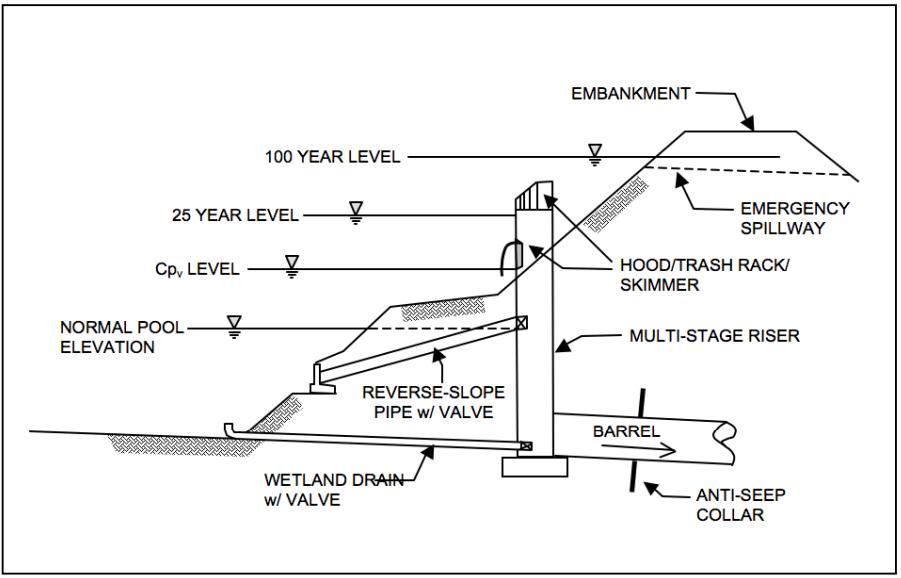
WQv/CPv LEVEL


WETLAND DRAIN w/ VALVE
The remainder of this page is intentionally left blank.
Figure
Figure 5.10.7. 2 Examples of Stormwater Wetland Outlet Structures
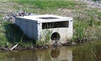
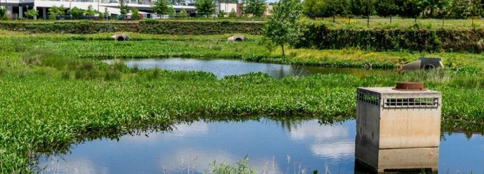
5.10.8.
Design Procedure
Table 5.10.8.1 provides the design procedure for a stormwater wetland.
Table 5.10.8.1 Design Procedure
Step
Step 1
Step 2
Step 3
Design Activity
Evaluate stormwater wetland feasibility, goals, and primary function.
Use the feasibility criteria provided in Tables 5.10.3.1 and 5.10.4.1 to determine if a stormwater wetland is feasible for the selected location on the land development site. Consider especially whether it is appropriate for the proposed development based on the intended land use of the property, the maintenance burden, and assumptions or knowledge of how the property owner(s) will care for the wetland after construction (e.g., self-maintenance, property/facilities management maintenance, landscape contractor). If possible, include the property owner(s) in the SCM selection since they will be responsible for maintenance.
Consider whether the intention is to:
Comply with the local government stormwater quality requirements (i.e., treat the WQv).
Include additional storage capacity for flood control.
Enhance landscape and provide aesthetic qualities
If a stormwater wetland is feasible based on the factors identified in the above row, evaluate its feasibility from a hydrologic perspective.
Perform the water balance described in Section 5.10.5 (Hydrologic Requirements & Design Options) above.
If the water balance indicates a stormwater wetland is feasible, collect soil permeability and SHWT information per the requirements in Section 5.10.5 (Hydrologic Requirements & Design Options) above.
If the onsite tests indicate a stormwater wetland is feasible, determine the most appropriate design configuration (i.e., hydrologic support design, Level 1 or Level 2, and wetland type) based on the information provided in this design specification.
Create a rough layout of its dimensions, taking into consideration existing trees, utility lines, and other obstructions to ascertain if it will fit into the desired space, given its general design requirements.
Calculate the design storage volume for the contributing drainage area.
Use the required methods established in Chapter 3 (Standards, Methods, and SCM Selection) to calculate WQv for the wetlands contributing drainage area.
Level 1 stormwater wetlands (full control):
Determine the stage-storage relationship for the wetland.
Level 2 stormwater wetlands (WQv only):
Typically, the design storage volume (DSv) is equal to WQv, unless the wetland cannot manage the entire WQv or will be used to treat a volume larger than the WQv.
Photo sources: left – Clemson University; right – Dragonfly Pond Works
Step Design Activity
In areas to be planted, 4 to 6 inches of appropriate topsoil should be installed above liners/geotextiles to support wetland plantings. This must be accounted for when designing storage volumes.
Determine the approximate minimum surface area of the stormwater wetland.
A stormwater wetland is designed to always be inundated with water. Thus, the volume required for the permanent pool is not the WQv (for Level 1 wetlands) or WQv and higher, flood control volumes (for Level 2 wetlands) Rather, the WQv and larger temporary volumes must be contained above the permanent pool elevation (PPE). The required surface area of the wetland is then directly dependent on the required highest volume and the allowable depth of ponding in the temporary pool. The temporary pool ponding depth is set based on the depth that the wetland plants can sustain for several days after a rainfall.
The minimum surface area of the wetland is determined using the equation below.
Step 4
Step 5
���� = ������������
where:
A = surface area of total wetland ponding area (ft2)
DSv = highest design volume (ft3); for a Level 2 wetland, DSv = WQv
dT = temporary ponding depth (ft); ponding depth is up to one 1 ft
This minimum surface area calculation will slightly overestimate the surface area of the permanent pool required due to the sloped sides of the wetland and safety benching not yet designed Do not adjust the calculation.
Design pool soils and liners for dike stability and hydrologic support establishment.
Design the geotextiles and erosion matting for slope stability, where needed.
Include specifications for impermeable liners if required to maintain wetland hydrology.
Determine the approximate surface areas and depths of the stormwater wetland pools/zones, including the forebay. Refine the volumes and design the wetland topography.
Use design specifications provided in Table 5.10.7.2 (above) to for this purpose
Step 6
Step 7
Step 8
Step 9
Prepare a grading plan showing the wetland areas and depths, accounting for necessary liners, topsoil (4 to 6 inches), and safety benches in all deep pools, including the forebay. Determine the final volume of water below the permanent pool elevation and within the temporary storage volume above the permanent pool elevation.
Confirm that: �������� ≥ ������������ ; where VT = the temporary storage volume (ft3).
Refine the topographic design (and grading plan) until DSv is accurate and the above equation is true.
Size the outlet structure and any flow regulators.
Use Sections 5.16 (Inlets, Energy Dissipation, and Pretreatment Measures) and 5.17 (Overflow Controls) for requirements.
Design the vegetation and protection measures.
The vegetation design shall be in accordance with the vegetation design requirements provided in Table 5.10.9.1
Design safety measures and wetland protection measures external to the pools, if needed.
Safety measures may include fencing, signs, and other protective features as appropriate for the proposed development. Use guidance found in Section 5.10.8 (b elow) to design protection measures.
5.10.9. Vegetation Design Requirements
Plants are critical to stormwater wetland performance and function. Plants filter, take up water and nutrients (which can be pollutants) through their roots, and transpire stormwater. These mechanisms provide pollutant removal. Plants also
Northeast Tennessee Water Quality SCM
maintain the health of the wetland by preventing erosion and providing organic matter for nutrient replenishment. This provides habitat for aquatic and soil organisms and maintains the hydric conditions appropriate for the wetland.
Beyond their stormwater function for a land development, stormwater wetlands can also be considered aesthetic elements. With careful consideration, the vegetation aesthetic of these wetlands can integrate with, and even enhance, the overall landscaping of the land developments in which they are located.
The importance of plants to stormwater wetland function means they, like any SCM component, have design, installation, and maintenance specifications. Much of the design and maintenance of a stormwater wetland center on plant coverage and replacement. Table 5.10.9.1 provides the vegetation specifications for stormwater wetlands. Plant selection requirements and guidance is provided in Table 5.10.9.2
Table 5.10.9.1 Vegetation Design Specifications
Safety bench (including benches in deep pools) 60% within one year of wetland construction
High marsh
Low marsh
20% within one year of wetland construction
Deep pools No target
Lowland
(and wetland buffers, if included in design, not shown in Figure 5.10.6.1)
100% of areas stabilized upon construction termination and fully (100%) vegetated within one year of wetland construction
Install emergent2 wetland species that have high colonization and growth rates; the ability to establish large, dense populations even in winter (for pollutant removal); and are robust in continuously or periodically flooded environments.
Greater plant diversity, density, and numbers are expected in the high marsh and on safety benches, due to greater sunlight and nutrient support via wildlife and stormwater inflows.
Live plants shall be used for wetland construction. Wetland seed mixes are prohibited due to the probability of displacement by stormwater inflows before plants are fully and securely rooted.
Install emergent2 wetland species, only on safety benches.
Deep pool areas below the safety bench generally do not support emergent wetland vegetation. Deep pools may support submerged or floating vegetation, and these plants are recommended if available.
Install non-wetland species. Both woody and non-woody vegetation is permissible, including trees.
Select plants/trees that can tolerate repeated cycles of inundation and drought. Avoid plants/trees that experience seasonal leaf drop and have seed pods that float as these can too easily clog outlets.
Areas of bare soil and impervious surfaces are not allowed.
Loose, light ground cover, such as mulch and pea gravel, is not allowed in lowland areas due to the potential for outlet clogging. Use only vegetative soil stabilization methods.
1 Minimum target coverage is the required surface area that must be covered by vegetation within the specified timeframe.
2 Emergent plants are rooted in shallow water or near the water’s edge, and therefore encounter full-time or frequent inundation. If rooted underwater, their leaves and stems typically extend out of the water. These vascular plants often have deep and dense roots that stabilize shallow soils. Just as importantly, they also provide habitat for birds, insects, microorganisms, and other animals living in or near water, or in the soil where plants are rooted. In turn, the presence and activities of wildlife sustain the wetland plants and soil
The remainder of this page is intentionally left blank.
Wetland Zone
(see Figure 5.10.6.1) Minimum Coverage1 Vegetation Specifications
Table 5.10.9.2 Vegetation Selection Requirements and Guidance
Vegetation Design Element
Plant Selection
Plant Diversity Guidance
Specification(s)
Select plants suitable for use in local conditions, based on specific site, soils, and hydric conditions expected at the plant’s intended location within or adjacent to the wetland, and the desired aesthetic. Plants tolerant of salt are recommended for areas that will encounter high salt loads in the winter. In all cases, native plant species suited to local hydrologic conditions are recommended.
Non-native, invasive species are prohibited as these can result in dense monocultures that do not foster insect, animal, or plant diversity, thus degrading wetland plant growth and overall wetland health.
For guidance on appropriate plant species, consult a plant and landscape expert, such as a landscape architect, local nursery, or Master Gardener from the Tennessee Extension Master Gardener program (https://mastergardener.tennessee.edu/). More information on wetland plants can be found at the following websites:
The Tennessee Wetland Plant list from the University of Tennessee Extension Horticulture Team at https://www.uthort.com/
http://wetlands.fws.gov/
https://plants.usda.gov/home/wetlandSearch
Plants suitable for United States Department of Agriculture Plant Hardiness Zoned 6b and 7a (depending on your zip code) are recommended.
More information on nuisance emergent plant species in Tennessee can be found at:
Tennessee Wildlife Resource Agency. Tennessee Aquatic Nuisance Species Management Plan. February 2008.
Consider future maintenance needs of vegetation when designing the wetland. The level of plant care needed to maintain the landscape should influence plant selection to minimize care needs as much as possible.
The list below is an example of the level of both species and maturity diversity desired in stormwater wetland vegetation designs. Use of this example is not mandatory.
Stormwater wetlands should have a minimum of 10 different species total, of which at least 5 are emergent species, with no more than 30% of a single species.
Minimum plant quantities and sizes per 200 ft2 of high marsh and safety bench area:
50 herbaceous plants in at least 4 cubic-inch container (equivalent to 2 ft on center minimum; 1.5 ft on center recommended).
Lower density of the same diversity/plants as used in the high marsh shall be planted in low marshes.
Minimum plant quantities and plant sizes per 200 ft2 of lowland area:
50 herbaceous plants that come from a container having a minimum volume of 4 cubic inches, OR
8 shrubs which come from a container having a minimum volume of 1 gallon (equivalent to shrubs planted 5 ft on center minimum; 3 ft on center recommended), OR
1 tree which comes from a container having a minimum volume of 3 gallons and 40 grasslike herbaceous plants from containers having a minimum volume of at least 4 cubicinches
Northeast Tennessee Water Quality SCM Manual
Compliance with the vegetation standards set forth above shall be shown in a vegetation plan that is included with the water quality management plan (WQMP). An example of a vegetation plan for a stormwater wetland is provided in Figure 5.10.7.1. Plan preparation requirements are below.
The plan must be prepared by a professional qualified in landscape design by their education or experience.
The plan shall include one or more labeled plans/details (to scale) showing the plants to be installed, their numbers, and locations. Plan notes showing a plant schedule and installation instructions are encouraged. This additional information allows both the plant installer at the time of construction, as well as the person(s) responsible for maintenance of the SCM after construction, to understand the original vegetation design and its compliance with the minimum standards.
Landscaped SCMs may not be recognized under the local government’s codes as property landscaping. Therefore, additional requirements for property landscaping may apply.
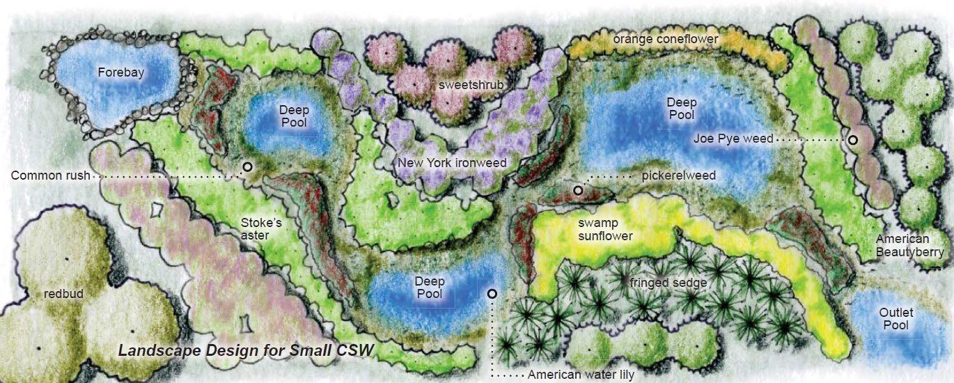
5.10.10. Protection Design Guidance
SCMs designed for stormwater quality purposes must be maintained in keeping with the approved SCM design for the life of the land development 1 Design professionals can assist property owners with this requirement by including protective features in and around SCMs to limit the potential for damage by external factors. Often, the landscape and impervious features around an SCM can be tailored to its specific needs, and therefore used to protect its critical components.
Protection is especially important for the wetland plants and outlet structure which are key to pollutant removal and wetland water levels and flow rates, respectively Stormwater wetlands are especially well-suited to a variety of protection methods that can enhance the landscape aesthetic, listed in Table 5.10 10.1 and shown in Figure 5.10 10.1
Table 5.10.10.1 Stormwater Wetland Protection Measures*
Natural fencing such as vegetation borders/screens (woody/prickly shrubs, dense or tall grass)
Driveways, sidewalks, or walkways around the SCM
Observation decks, benches, and safe viewing areas
Hardscaping, such as Block or cobble/boulder edging or walls
Educational or directive (e.g., no pets) signs
Pet waste stations and trash cans near the SCM
* The list presented in the table is not exhaustive. There may be other possible protection measures.
1 Tennessee Rule 0400-40-10-.04
5.10 Stormwater Wetland Design
Version: September 1, 2024
Figure 5.10.9.1 Example of a Stormwater Wetland Vegetation Plan (Source: Alabama LID Manual)
Examples of Protective Landscaping for a Stormwater Wetland
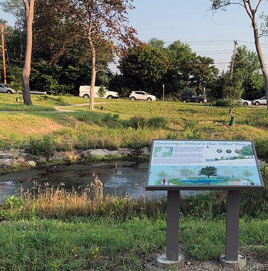

5.10.11. Site Preparation and Land Disturbance Requirements
The following information is provided to support proper and effective construction and protection of stormwater wetlands during land disturbance activities and site construction. Mandatory requirements are identified using “shall” or “must.” All other statements can be regarded as non-mandatory guidance. Site preparation and land disturbance practices described in this section shall be shown on the Erosion Prevention and Sediment Control (EPSC) plan for the proposed land development. Table 5.10 11.1 provides requirements for site preparation and land disturbance practices for land developments with stormwater wetlands.
Table 5.10.11.1 Site Preparation and Land Disturbance Requirements for Stormwater Wetland
Site Preparation
Land Disturbance
5.10.12.
For safety purposes, a protection zone should be placed around the perimeter of the stormwater wetland once excavation begins. Mark the zone with highly visible orange fencing (or similar visible protective measures) and signage to advise construction personnel of wet conditions and potentially deep excavations.
Once constructed, protect the wetland using EPSC measures to prevent sediment discharges that could smother installed plants and healthy wetland soils, and clog outlets It is best to construct the stormwater wetland after the area draining to it has been fully and permanently stabilized.
Installation Requirements
The information in Table 5.10.12.1 provides a typical construction sequence to properly install stormwater wetlands. These steps may be modified to reflect different applications or site conditions. Installation practices shall be shown in the EPSC and WQMP plans, as appropriate for the proposed land development.
Figure 5.10.10.1
Left: A stormwater wetland with a safety bench and educational signage (Source: Horsely Witten Group); Right: A wetland with walking paths and fencing that suggests pedestrians should stay out of the wetland (Source: Watershed Company)
Table 5.10.12.1 Installation Steps
Step
Step 1
Step 2
Step 3
Step 4
Step 5
Step 6
Step 7
Requirement
The installation site shall be checked for existing utilities prior to construction.
Supervision during construction is required to ensure the stormwater wetland is constructed/installed in accordance with the approved EPSC and WQMP plans. The design professional or a designee under their supervision must inspect the stormwater wetland at critical stages of construction. Examples of critical stages of construction include excavation of the various wetland pools, grading of dikes, outlet construction, plant installation, and final inspection. This ensures that the contractor’s interpretation of the plan is consistent with the design professional’s intentions and allows the design professional to certify (in the as-built plan) that the wetland is built in keeping with the permitted plan.
During the preconstruction meeting, review and confirm that the actual boundaries of the wetland’s contributing drainage area and inlet elevations conform with the approved design.
Any changes that result from the preconstruction meeting must be shown as a revision to the WQMP and resubmitted to the local government for approval.
Install any stormwater diverters/flow blocks that may be necessary to divert stormwater flows from the wetland areas during its construction.
Since most wetlands will intercept the water table, construct the outlet structure first (or if not feasible, with the construction of the embankment) to control the water level in the wetland during excavation.
Construct the embankment in 8 to 12 inch lifts or as directed by geotechnical recommendations and compact as required with appropriate equipment. Ensure that the top invert of the emergency spillway (if located on the embankment) is constructed to be level and at the proper design elevation.
Compaction reports must be kept, reviewed, and approved by the design professional before submission to the local government with the as-built plan and engineer’s as-built certification.
Excavate and grade the wetland to its appropriate configuration and dimensions, working from the outlet and moving toward the inlet, until the appropriate elevations and desired contours are achieved for the bottom and side slopes of the wetland.
For excavation of large wetlands, use a cell construction approach where the wetland is split into 500 to 1,000 square foot temporary cells with a 10 to 15 foot earth bridge in between. This allows cell excavation from the sides.
Tracked excavators are recommended, especially on wet sites. Toothed buckets are recommended to avoid smearing and unintended soil compaction. A hydraulic thumb attachment for the bucket is especially useful for removing debris, placing structures, and scarifying soil surfaces.
Special protection measures, such as erosion control fabrics, may be necessary to protect vulnerable side slopes from erosion during the construction.
Add topsoil and soil amendments.
Equipment should not be allowed to traverse over the planting soil, once placed. Planting soil should be tamped as directed in the design specifications, but it should not be overly compacted.
If necessary, use a hydraulic thumb excavator attachment to break up the soil, especially large clumps. Scarification, chiseling, or ripping the top layer of soil is recommended especially if unintentional compaction occurred during construction or the site has suffered drought conditions.
After topsoil is placed, it should be saturated and allowed to settle for at least 1 week prior to installation of plants.
Install temporary irrigation measures, if needed, to ensure plants will be watered during the remainder of site construction.
Step 8 Install plants and surface covers as shown in the approved vegetation plan.
Step Requirement
Erosion/sediment control devices can be removed from the inlets once the wetland’s side slopes have good vegetative stability, and the drainage area is fully and permanently stabilized.
Step 9
Step 10
If the area draining to the wetland includes newly installed asphalt, the erosion/sediment control devices in place to block the inlets should remain in place for at least three storm events after asphalt installation. A substantial amount of fine particles and grit are discharged from newly installed asphalt during the first several storms that produce stormwater after installation. Maintenance will be required to remove the particles and grit if erosion/sediment control devices are removed too early.
Maintain the stormwater wetland in keeping with Section 5.10.13 (below).
Prepare the Record Drawing and submit to the local government for review and approval with the engineer’s as-built certification before a temporary or final Certificate of Occupancy can be obtained.
Advise the landowner (i.e., the person(s) taking ownership of the property immediately after its development) of the presence of the stormwater wetland and provide them with a copy of the property’s Record Drawing. The plan must clearly show the location of the stormwater wetland on the property and list the activities (and their frequencies) necessary for its proper maintenance.
5.10.13.
SCM Maintenance on an Active Construction Site
SCM maintenance is regulated by local government ordinance from the moment they are installed. As well, SCMs must pass a final inspection prior to construction termination. This inspection will be performed to ensure they are constructed in accordance with the approved WQMP, undamaged, and free of sediment and debris. Thus, SCM maintenance is good practice to ensure construction termination goes smoothly. Relevant policies are as follows:
The property owner is responsible for SCM maintenance. If the property is still an active construction site, these responsibilities may fall to the land disturbance permittee until the project receives final approval from the local government and/or a Certificate of Occupancy.
Property owners may have others, such as a site contractor or landscaping company, maintain the stormwater wetland on their behalf. However, the local government will hold the property owner responsible for ensuring it is maintained in proper operating condition (i.e., as designed and constructed) regardless of who performs maintenance activities.
Maintenance activities, which include ensuring proper operation of the SCM as designed and required SCM inspections, must begin immediately following installation of the stormwater wetland.
Maintenance activities shall be performed in keeping with the Northeast Tennessee SCM Inspection and Maintenance Manual. Additional guidance on maintenance of newly installed stormwater wetlands located on active construction sites is provided in Table 5.10.13.1 Area
Keep the contributing drainage area clean. Sweep trash, debris, and sediment frequently so that it does not wash in the wetland during a rain event.
Contributing
Drainage Area
Stormwater
Wetland Area
The area should be fully stabilized before installation of the SCM. If it is not, prevent inflows to the SCM by blocking or using diversion measures until the contributing drainage area is fully stabilized.
Stabilize the area as soon as possible to prevent the discharge of sediment to the SCM.
Cover stockpiles of construction and landscape materials to prevent their exposure to rainfall.
Ensure SCM plants are watered and growing as expected
Remove and replace diseased, dying, or dead plants as soon as they are noticed.
Table 5.10.13.1 Maintenance Activities for Newly Installed Stormwater Wetlands
Area or Component
Education
Post-Installation Maintenance Requirement
Check the forebay regularly to monitor sediment accumulation and remove sediment, trash, and debris as needed.
Beyond the forebay, ensure the wetland remains free of sediment and wastes.
Inspect the wetland for erosion or significant sediment buildup downstream of the forebay; immediately determine and eliminate the cause and repair the area.
Keep an eye on the wetland water levels after storm events to determine if the outlet structure is operating as expected. The wetland should return to its permanent pool elevation with two days, under normal climatic conditions.
If the wetland dries out too quickly or beyond expectations, or experiences long-standing high water when not expected, inspect the outlet structure and main flow path for clogging and damage; remove clogs and repair or replace damaged components as soon as they are noticed.
Alert onsite subcontractors to the SCM and the following requirements:
No muddy vehicles or equipment in the drainage area to the wetland.
No stockpiling of material in the wetland and no exposed stockpiles in the drainage area.
Block inlets prior to asphalt placement in the drainage area.
Remove sediment, trash, debris, and empty trash cans frequently.
Advise landscaping subcontractors on proper protection and maintenance of the stormwater wetland especially the following:
No dumping of lawn clippings or landscape debris
Plant maintenance needs/requirements (see above).
The remainder of this page is intentionally left blank.
5.10.14. Schematics
Figure 5.10.14.1 Schematic of an ED Shallow Wetland (Source: Adapted from Atlanta Regional Council, 2016)
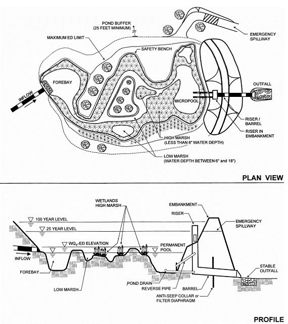
5.10.14.2 Schematic of a Basin/Shallow Wetland System (Source: Adapted from Atlanta Regional Council, 2016)
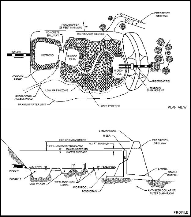
Figure
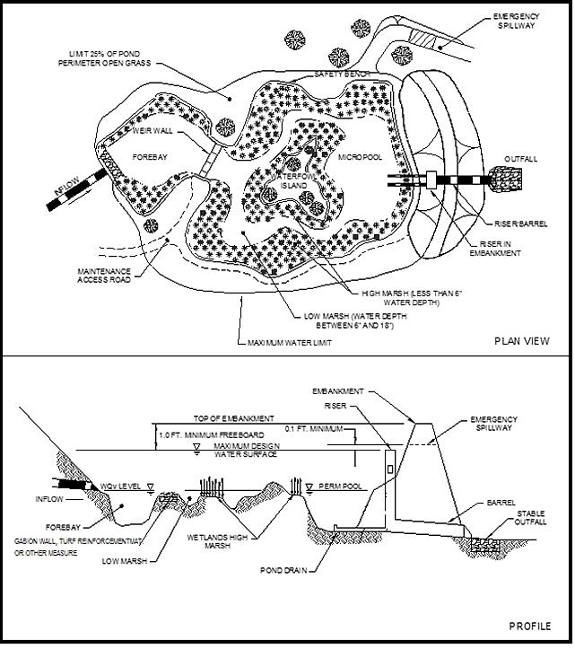
Figure 5.10.14.3 Schematic of a Shallow Wetland (Source: Adapted from Atlanta Regional Council, 2000)
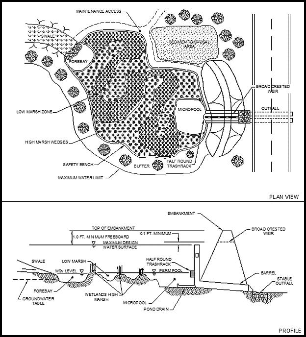
Figure 5.10.14.4 Schematic of a Pocket Wetland (Source: Adapted from Atlanta Regional Council, 2016)
Northeast
5.10.15.
References
ARC, Georgia Stormwater Management Manual Volume 2 Technical Handbook, 2016 Edition. Atlanta Regional Commission, 2016
USDA-NRCS et al., A Handbook of Constructed Wetlands. A Guide to Creating Wetlands for Agricultural Wastewater, Domestic Wastewater, Coal Mine Drainage, Stormwater in the Mid-Atlantic Region. Volume 1. General Considerations. United States Department of Agriculture – Natural Resource Conservation Service.
USDA-NRCS et al., Field Indicators of Hydric Soils in the United States. A Guide for Identifying and Delineating Hydric Soils, Version 8.2, 2018. United States Department of Agriculture – Natural Resources Conservation Service.
5.11 Submerged Gravel Wetland
design specification
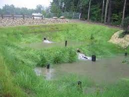
Water Quality Volume (WQv) Rainfall Group 3 Design
P = 2.5 inches or the first 75% of the volume of the 1-yr, 24-hour storm, whichever is less
OTHER SCM ATTRIBUTES (cost
Channel Protection Volume (CPv) No
Detention / Retention Control No
Small Storm Local Flood Control No
Typical SCM Footprint Size (percent of contributing drainage area) Minor
Construction Cost
Operation & Maintenance Cost (when properly maintained)
SCM Group: 3
Overview
A submerged gravel wetland is an SCM that uses wetland plants in a rock media to provide stormwater quality treatment. Filtration of sediment is the primary pollutant removal mechanism. Secondary mechanisms include biological uptake from algae and bacteria, and nutrient uptake from plants. Unlike a stormwater wetland, submerged gravel wetlands function as stormwater quality treatment facilities only, and thus do not provide flood control (detention).
ADVANTAGES/BENEFITS
Suitable for space-limited areas
High pollutant removal
DISADVANTAGES/LIMITATIONS
High maintenance requirements
Not suitable for high relief topography
Stagnant water and mosquitos can be an issue when not properly maintained
DESIGN CONSIDERATIONS FOR LOCATION, SIZING, & COMPONENTS
Best in locations with a high water table or poorly draining soils
On-line design configuration is prohibited
Drainage area range is 1 to 5 acres
Local slope must be less than 4%
Elevation drop (inlet to outlet) of 2 to 5 feet is necessary
Can be allowed to intersect the water table for most applications
Sediment forebay(s) are required for pretreatment
Safety measures must be included
DESIGN CONSIDERATIONS FOR LONG-TERM PROTECTION
Primary concerns are damage from unwanted entry
Suitable for a wide variety of protective and aesthetic designs (vegetated borders, hardscaping, fencing, signage, etc.).
DESIGN CONSIDERATIONS FOR LONG-TERM MAINTENANCE
Primary maintenance concerns are inlet and outlet clogging, which can lead to decreased pollutant removal, stagnant water, and mosquitos
Primary routine maintenance activities will be removing debris from inlet and outlet, pretreatment cleaning, and plant care (e.g., removing invasive or dead/dying vegetation, etc.).
Consider permanent signs to prohibit entry
If part of a pedestrian area or trail, consider permanent signs and provide pet waste stations with trash cans
Source: Thomas P. Ballestero; University of New Hampshire Stormwater Center.
Northeast
5.11.1 General Description
Submerged gravel wetlands (SGWs) are low-impact development (LID) stormwater control measures (SCMs) originally developed for use in wastewater treatment. In the late 1990s, the Center for Watershed Protection introduced this SCM for stormwater management. Usage is growing because of their high level of treatment, especially for nutrients. (Roseen et al, 2012).
SGWs have the look and function of natural wetlands, however there is no permanent pool of water on the surface. Rather, SGWs consist of one or more treatment cells filled with crushed rock or gravel, topped with planting media, and densely vegetated with wetland plants. Stormwater flows subsurface through the root zone of the plants, where sediments are removed via filtration. The plants also provide nutrient uptake. The outlet from each cell is designed so the rock/gravel layer remains submerged. This design creates anaerobic conditions below the surface where algae and microbes on the rocks provide biological uptake, providing significant treatment of pollutants such as nutrients. Thus, an SGW relies on the pollutant-stripping ability of plants and soils to remove pollutants from runoff. The result is highly effective stormwater treatment.

5.11.2 Design Applications
Design applications for SGWs require a permanent wetland pool that can be sustained, either through a large enough drainage area and poorly draining soils or an impermeable liner, a location where the SGW can intersect the groundwater table. SGW provide stormwater quality treatment only, thus they can fit into relatively small areas/applications. Multiple SGWs designed in parallel can serve much larger areas. Figure 5.11.2.1 shows examples of SGWs.
Figure
5.11.2.1
Examples of Submerged Gravel Wetlands
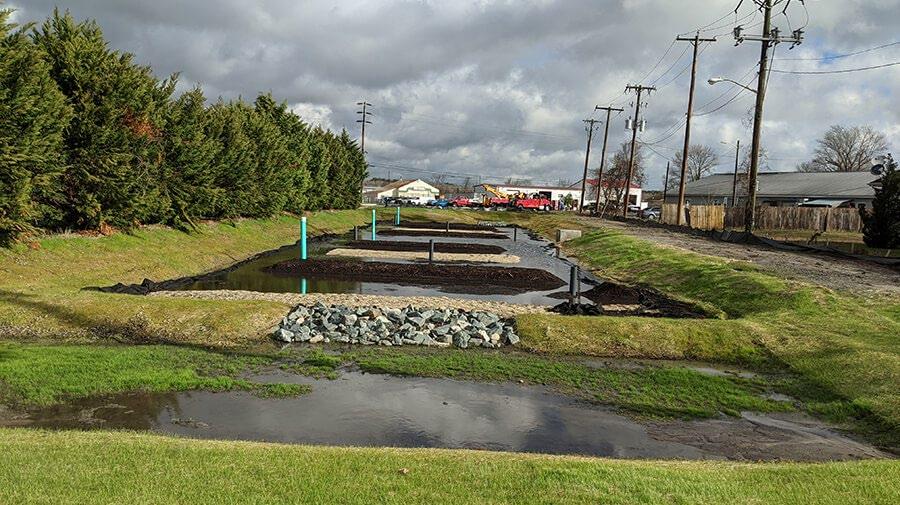
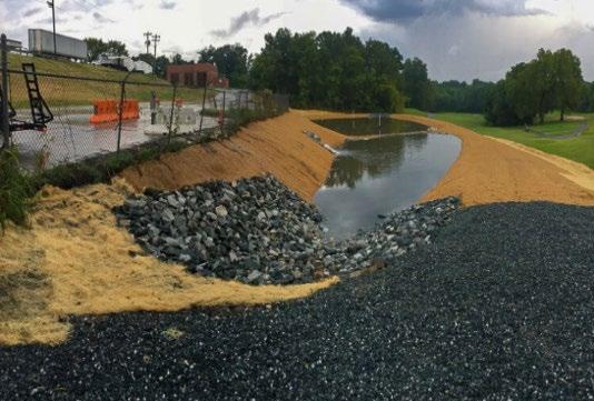
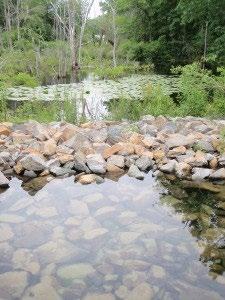
Top left: Submerged gravel wetlands that receives stormwater from nearby roadways and commercial businesses in Berlin, MD (Source: Maryland Coastal Bays Program); Top right: Submerged gravel wetland treats runoff from a commercial development in Greenland NH (Source: Water Environment Federation); Bottom right: A schematic showing the main components of a submerged gravel wetland. Bottom left: A newly constructed submerged gravel wetland in Greensboro NC after a storm. The forebay is in the foreground (Source: Dragonfly Pond Works)

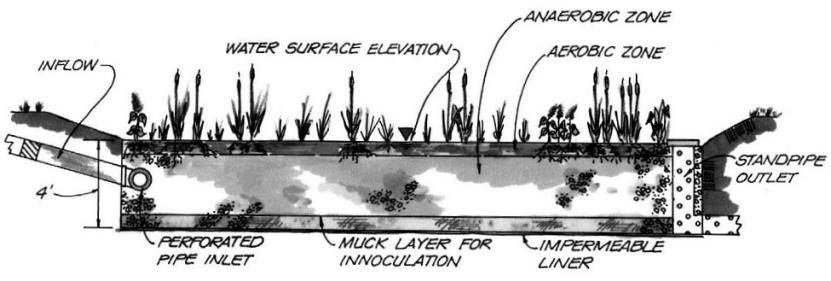
Northeast
5.11.3
SCM Suitability
Use Table 5.11.3.1 to determine if a SGW is suitable for the application being considered.
Table 5.11.3.1 Suitability Factors
Factor
Stormwater Quality Treatment
Suitability
SGWs designed in keeping with the specifications established herein will satisfy local government stormwater quality treatment standards
Channel Protection SGWs do not provide channel protection.
Detention SGWs are not suitable for flood control (stormwater detention).
SGWs can be used to address the following common stormwater pollutants:
Pollutant Treatment
Capability
Treatment of Waste and Other Pollutants
1 – Rossen, Robert M., et al , 2012
2 – Georgia Stormwater Management Manual, Volume 2 Technical Handbook, 2016 Edition.
3 – Cadmium, Copper, Lead, and Zinc
SGWs shall not be used to treat the following pollutants:
Construction sediment/waste
Landscape storage or waste
Sewage, pet, and livestock waste
Medical waste
Household & commercial wastes
Hazardous wastes
Gasoline, motor oils, greases, and other petroleum-based products
Fats, oils & grease (from food preparation)
Pesticides, fertilizers, herbicides
Other byproducts and waste materials expected, based on the property’s land use
Privately owned SGWs are not allowed in the public right-of-way.
General suitability criteria by land-use type are as follows. See Chapter 3 (Standards, Methods, and SCM Selection) for more information.
Suitability by Land Use
5.11.4
*These policies do not preclude the use of submerged gravel wetlands on individually owned single family or multi-family residential lots. However, submerged wetlands placed on residential lots will not be considered by the local government as suitable for compliance with local government stormwater management requirements due to the inherent difficulties in oversight and enforcement of long-term protection and maintenance requirements on residential lots
SCM Location Requirements
Location constraints for SGWs are provided in Table 5.11.4.1.
Table 5.11.4.1
Location Requirements
Physical Element
Minimum SCM Setbacks
Requirement
Minimum setbacks for SGWs, measured from the edge of the SCM, are as follows:
10 feet from property lines.
100 feet from private water supply wells; if the well is downgradient from a hotspot land use, then the minimum setback is 250 feet.
Physical Element
Flow Avoidance
Utility Avoidance
Requirement
TDEC specified distance per designated category from public water supply reservoirs
50 feet from underground septic systems.
SGWs shall not be located:
where they will receive inflows from sump pumps, wash stations, or other non-stormwater discharges.
in a natural wetland, stream, or other navigable waters of the United States.
All utilities shall be located outside of the SGW’s water quality easement
5.11.5 Design Intention and Schematics
A SGW is designed as an underground flow through treatment system where the stormwater travels horizontally through a saturated gravel substrate with a microbe rich environment. A sediment forebay or other pretreatment device precedes flow into the wetland treatment area. By design, the WQV is temporarily retained in the basin geometry above the wetland soil, drains into the gravel treatment area via a subdrain, and is subsequently treated through the SGW before draining to stormwater conveyance or receiving waters. The gravel substrate within the wetland’s cell(s) is intended to be continuously saturated below a depth of 4 to 8-inches from the SGW’s surface grade in order to promote water quality treatment conditions and support wetland vegetation. To force this near-surface groundwater condition the primary outlet from the gravel layer has an invert below the wetland surface grade.
Standing water of significant depth is not expected in a SGW other than during large rainfall events. An overflow outlet (or spillway) must be included in the design. Outlets can be combined to control the WQv, establish a maximum ponding depth, and allow for the overflow contingencies of larger storms through an overflow outlet or structure.
Figures 5.11.5.1 and 5.11.5.2 show the conceptual schematics of this SCM. As indicated by the schematics, design variations exist, but all SGWs have the following basic components.
Inlet(s)
Pretreatment area (not shown)
Wetland plants
Wetland soil layer
Filter layer
Rock/gravel layer
Subdrain(s) and outlet(s)
Overflow device(s)
A maintenance easement and maintenance access location(s)
Where appropriate, design specifications (e.g., pipe diameter, soil depths, etc.) have been left in the schematics to support variations in designs proposed while using this manual. Design specifications for submerged gravel wetlands are provided in the sections that follow the schematics.
The remainder of this page is intentionally left blank.
5.11.5.1 Schematic of SGW with Inflow and Outflow Control Structures (No Subdrain)
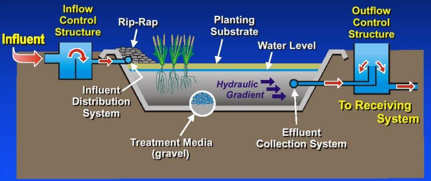
5.11.5.2 Schematic of Submerged Gravel Wetland with Standpipe and Subdrain Distribution
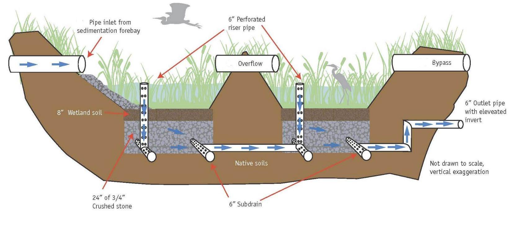


Figure
Figure
Source: Roseen, Robert M., et al, WEF, 2012
WQv outlet
Large flow bypass


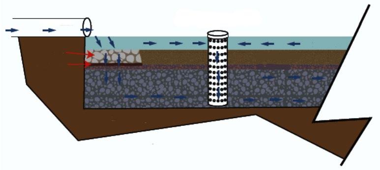
5.11.6 Design Requirements


The criteria provided in Table 5.11.6.1 shall be considered minimum standards and specifications for the design of submerged gravel wetlands and their contributing drainage areas.
Table 5.11.6.1 Design Specifications
Design Element
Water Quality Volume (WQv)
Use in a Water Quality Treatment Train
Design Configuration
Maintenance Access and Easement
Specification(s)
The water quality rainfall depth (P) for determination of WQv is P = 2.5 inches, or the WQv is the first 75% of the volume of the 1-yr, 24-hr storm, whichever is less. The design professional can select which volume to use.
Acceptable methods to determine WQv are presented in Chapter 3 (Standards, Methods, and SCM Selection).
If the SGW cannot manage the entire WQv for its contributing drainage area, it must be placed in a treatment train with another SCM. See treatment train policies and calculations in Chapter 3 (Standards, Methods, and SCM Selection) for treatment train policies and calculations.
SGWs shall be designed and constructed in an offline configuration (away from the main flow path for the drainage area)
A diversion structure must be included to redirect the WQv from the main flow path to the SGW while still allowing larger flows to remain in the main flow path. The structure shall include a low-flow orifice, weir, or other hydraulic structure, sized to pass the water quality peak discharge (Qwq) and direct it to the offline wetland. See Chapter 3 (Standards, Methods, and SCM Selection) for the calculation of Qwq.
Flow regulators (flow splitters, diversion structures, and overflow structures) shall be designed in keeping with Section 5.17 (Overflow Controls).
The entire SGW must be accessible for maintenance without requiring the entry of vehicles or heavy equipment in the wetland.
A maintenance easement to (and including) the SGW must be provided from a public roadway. The easement must be free of permanently affixed obstructions (e.g., trees, pools, fences without gates, permanent signs, etc.) to allow maintenance vehicles and equipment to safely pass.
Figure 5.11.5.3 Schematic of SGW with Secondary Inlet (Standpipe Distribution Only)
Secondary inlet to gravel layer (slotted pipe with solid cap
Inlet culvert from forebay
Outlet not shown
Ponding zone
Wetland soil layer
Gravel
Gravel
Riprap
Woven geotextile
Low permeability soils
Pea gravel layer
Design Element
Minimum Drainage Area
Slope
Ponding Depth
Minimum Hydraulic Head
Drawdown & Residence Time
Minimum Depth to Water Table
Specification(s)
Minimum contributing drainage area = 1 acre.
Maximum contributing drainage area = 5 acres
Slope in the area of the SGW must be relatively flat (< 4%)
Side slopes within the SGW shall not exceed 3H:1V, primarily to facilitate maintenance.
Maximum ponding depth = 24 inches.
Minimum hydraulic head = 2 to 5 feet (from inflow to outflow)
Drawdown for the outflowing WQv shall be within 72 hours.
The desired minimum residence time of the inflowing WQv is 24 to 30 hours for optimal nitrogen treatment, although climatic conditions may dictate otherwise during wet weather periods.
SGWs can intersect the groundwater table unless:
they will receive stormwater from drainage areas that are expected to generate higher than typical amounts of sediment, phosphorus, nitrogen, fecal bacteria, or metals;
will be located above an underlying water supply aquifer;
will be located where soil contamination is known or suspected
If any of the above three conditions exist, a separation distance of 2 feet is required between the bottom of the gravel and the elevation of the seasonally high water table to prevent groundwater contamination. An impermeable liner is also required (see ‘In-situ Soil / Liner’ row below).
Soil borings shall be used to determine the seasonally high-water table. See Appendix F (Policies
Geometry for Soil Infiltration Tests & Soil Borings) for soil boring requirements.
Minimum wetland cell length (flow travel distance within the gravel layer) = 15 feet
Beyond this minimum length, SGW cell geometry will depend on the required WQv, available surface area, and minimum/maximum layer thickness described herein.
Inflows shall be non-erosive (maximum velocity of 5 ft/sec). Use rip-rap aprons or other energy dissipation methods as needed.
Pretreatment shall be provided immediately downstream of each inlet to control the sediment entering the SGW, except for inlets that supply 10% or less of the total inflow to the SGW.
Pretreatment options include a sediment forebay, an off-line deep sump catch basin, or hydrodynamic separator (i.e., Group 4 MTD). Specifications are below. Additional requirements are provided in Section 5.16 (Inlets, Energy Dissipation and Pretreatment Measures).
Inlets, Energy Dissipation, & Pretreatment
Subdrain
Forebays and stilling basins shall be sized to hold 10% of WQv of the SGW When sizing the SGW, this pretreatment volume can be considered part of the WQv
Forebays or sumps shall be separated from the SGW by very low permeability or impermeable barrier, such as an overflow berm constructed of concrete, clay, or a fine geotextile or some combination thereof. The point of the separation is to avoid water seepage and soil piping through earthen dividers.
Forebays may contain a fixed vertical sediment depth marker to measure sediment deposition over time. Although not required, consider hardening the bottom of the forebay/sump with concrete or pavers to facilitate easier sediment removal.
Pretreatment devices shall include measures to capture litter, leaves, trash, and other floatables for SGWs that are expected to readily encounter these materials
Drainage distribution throughout the gravel layer must be facilitated by a perforated pipe subdrain, which allows for flow distribution, flow through, and a constant water surface elevation
Two different configurations are shown above in Figures 5.11.5.2 (required for multi-cell SGWs) and 5.11.5.3 Specifications are as follows:
Design Element
Pipe diameter = 4 to 6 inches
Specification(s)
For SGWs without a horizontal subdrain system, a minimum of one vertical, perforated standpipe is required, placed in the center of the SGW and extending from the maximum ponding elevation to just above the bottom of the gravel layer. If multiple vertical standpipes are used, space them equally along the length (direction of flow) of the SGW, starting at the discharge point of the inlet(s). Horizontal, perforated subdrains are optional.
For multi-cell SGWs (see Figure 5.11.5.2 above):
A vertical, perforated standpipe shall be placed at the discharge point of the inlet(s), extending from the design ponding elevation (max. elev. = 24 inches) to just above the bottom of the gravel layer, where it attaches to a horizontal, perforated distribution subdrain pipe that spans the width of the SGW treatment cell The standpipe shall have a permanently affixed grate or screen to prevent inflows of debris and floatables through the top of the pipe.
A second horizontal, perforated distribution subdrain spanning the width of the treatment cell shall be located at the downstream end of the cell where it discharges into a solid wall pipe that transfers water from one SGW treatment cell to the next.
The most downstream perforated distribution subdrain discharges to the outlet.
One vertical cleanout shall be located in each subdrain section, rising to at least 12-inches above grade (not shown in Figure 5.11.5.2). A higher elevation may be needed to prevent the cleanout from getting obscured visually by wetland vegetation. Cleanouts shall be perforated or slotted only within the gravel layer, and solid within the wetland soil, filter layer, and storage area above. This is important to prevent short-circuiting and soil piping. Cleanouts shall be topped by a locked cap. Cleanouts also serve as observation wells.
The outlet shall be designed to allow a saturated condition to be permanently sustained within the SGW. The structure should consist of a weir, orifice, perforated standpipe, or other device, as appropriate to achieve and maintain saturation as well as drain the WQv within 72 hours
The outlet invert elevation should be 4 to 8-inches below the wetland soil's surface. Regardless of design, the primary outlet shall receive only water that has been filtered through the gravel layer, otherwise clogging can be problematic.
Outlet
Overflow
Care should be taken to not design a siphon that will drain the wetland; therefore, the primary outlet location must be open or vented. Smaller outlet controls do require protection of the “clean” or filtered side of the orifice from larger debris delivered by high flows or wind-blown mechanisms from the downstream side. This may mean that high flow contingencies are in secondary structures or at least situated such that large debris does not have access to the clean side of the orifice.
An optional high-capacity outlet at equal elevation or lower to the primary outlet may be installed for maintenance purposes. This outlet is plugged/sealed during normal operation but allows for flushing of the treatment cells at higher flow rates should that be desired. If it is located at an elevation lower than the primary outlet, it may be used to drain the system for maintenance or repairs.
Although SGWs are designed in an offline configuration, an overflow outlet or spillway, sized to pass the design flow from the 10-year, 24-hour storm event, shall be provided This outlet is sized by using conventional routing of the inflow hydrograph through the surface storage provided by the SGW. Take care to design the overflow in a manner that will not cause short-circuiting of the WQv.
Minimum freeboard = 6 inches.
Design Element
Controls for Waste & Other Pollutants
Specification(s)
Freeboard is measured from the top of the water surface elevation for the WQv to the lowest point of the ground surface elevation, not counting any outlet weirs
Appropriate controls shall be included in the design of the contributing drainage area to the SCM to address any waste and other Pollutants (see Table 5.11.3.1 above) expected on the property after construction. Use the proposed land use as a guide to determine appropriate controls. Examples of such controls include, but are not limited to, dumpsters, trash cans, covered materials/waste storage areas, covered materials transfer areas, oil and grease waste controls, and pet waste stations.
The remaining rows specify the subsurface layers of the SCM, starting at the bottom.
The graphic below presents a general schematic of SGW layers.
Subdrain standpipe (perforated)
Wetland plants
Wetland soil layer (minimum 8-inches) Pea gravel layer (minimum 3-inches)
Gravel layer sized to temporarily store 75% of the WQv (18 to 48-inches)
Layer Schematic
In-situ Soil / Liner
Subdrain (connects to outlet)
Liner layer
No horizontal layers of geotextile or geofabric shall be placed between SGW layers as this may clog and restrict root growth. However, geofabrics may be used:
below riprap aprons used for energy dissipation for incoming flow (see Figure 5.11.5.3)
as a liner between SGW walls and in-situ soil to prevent the migration of soil into the SGW
In-situ Soil
SGWs can be used in almost all soils and geology, with minor design adjustments for onsite conditions. The recommended maximum hydraulic conductivity of native soils below and surrounding the SGW is 0.028 ft/day. Thus, underlying soils of hydrologic soil groups (HSGs) C or D may be adequate to maintain wetland conditions, while HSG A or B soils will likely require an impermeable liner.
An impermeable liner shall be used at the bottom of the SGW for any of the conditions below.
In-situ soil has a surface infiltration rate greater than 0.1 ft/day
Karst conditions (sinkholes, etc.) are known or suspected in the area of the SGW.
Soil contamination is known or suspected in the area of the SG
The development served by the SGW is expected to discharge pollutants that either cannot be treated by a SGW or will be in excessive amounts.
Liner Options
Acceptable options for impermeable liners include:
Preferred: 30 mil High-Density Polyethylene (HDPE) liner (sealed seams)
Bentonite clay; minimum required depth = 4 inches.
Design Element
Coarse Gravel & Subdrain
Filter Layer
Wetland Soil
Wetland Plants
5.11.7
Specification(s)
Clay soil (minimum 15% passing the #200 sieve and a maximum permeability of 0.028 ft/day (1 X 10⁻⁵ cm/sec); required depth = 6 to 12 inches
Gravel
The gravel layer shall provide storage for approximately 75% of the required WQv, whereas the remainder of the WQv is temporarily stored in the sediment forebay (if present), filter layer, and ponding area above the wetland soil.
Minimum thickness = 18 inches; placed above the in-situ soil/liner
Maximum thickness = 48 inches.
Clean, washed, uniformly graded, angular gravel, having a minimum size of about ¾ inch and porosity of 40%; ASTM #57 stone is suitable
See also Subdrain row in this table (above).
Minimum thickness = 3 inches; placed above the gravel layer to prevent fine particles of wetland soil from migrating down into the gravel layer.
Clean, washed, natural pea gravel, approximately ⅜ inch.
Minimum thickness = 8 inches.
Guidance: The soil should have a hydraulic conductivity between 0.01 to 0.1 ft/day. It may be manufactured using a combination of loam, sand, and fine soil blended to a high % organic matter content (≥ 15% organic matter) Organic matter is a source of dissolved organic carbon to the gravel layer below. Avoid soil mixing with clay content in excess of 15%, as it may result in drying and cracking, causing fines to migrate into the subsurface gravel layer.
See Section 5.11.8 below for plant specifications.
Design Procedure
Table 5.11.7.1 provides the design procedure for an SGW.
Table 5.11.7.1 Design Procedure
Evaluate SGW feasibility.
Step 1
Step 2
Use the feasibility criteria provided in Tables 5.11.3.1 and 5.11.4.1 to determine if a SGW is feasible for the selected location on the land development site. Consider especially whether it is appropriate for the proposed development based on the intended land use of the property, the maintenance burden, and assumptions or knowledge of how the property owner(s) will care for the SGW after construction (e.g., self-maintenance, property/facilities management maintenance, landscape contractor). If possible, include the property owner(s) in the SCM selection since they will be responsible for maintenance
If a SGW is determined to be feasible and appropriate for the proposed development, create a rough layout of its dimensions, taking into consideration existing trees, utility lines, and other obstructions to ascertain if it will fit into the desired space, given its general design requirements.
Determine if an impermeable liner is required on the bottom and sides of the SGW. Infiltration tests of the in-situ soil are required if a liner is not specified in the design.
Calculate the required WQv.
Step 3
Use the hydrologic methods established in Chapter 3 (Standards, Methods, and SCM Selection) to determine the WQv for the SGW’s contributing drainage area.
Regardless of whether the SGW can control the entire WQv, channel protection volume (CPv) control must be provided by a separate facility (e.g., a wet basin, conventional detention, or ED basin)
Step
Step 4
Step 5
Step 6
Step 7
Step 8
Design Activity
Design the SGW treatment bed, subdrain, and outlet structure.
Optimally, the gravel layer is sized for 75% of the WQv, while the remainder is contained in the sediment forebay (if used), filter layer, and ponding area.
Size the overflow for the 10-year storm, and minimum freeboard of 6 inches.
Include trash racks, grates, covers, and other measures for safety and to prevent clogging of the outlet(s).
Design the pretreatment device.
If the device is a stilling basin or sediment forebay, size it to 10% of the WQv
Size and locate the inlet(s), energy dissipation, and flow diversion structure.
All SGWs are designed in an offline configuration, therefore a flow diversion structure must direct the WQv to the SGW while higher flows remain in the main drainage path. The diversion structure must be sized to allow the peak discharge of the water quality storm, Qwq, to flow to the SGW.
Use the hydrologic methods established in Chapter 3 (Standards, Methods, and SCM Selection) to determine the Qwq for the SGW’s contributing drainage area and size the flow diversion structure accordingly.
Use Sections 5.16 (Inlets, Energy Dissipation, and Pretreatment Measures) and 5.17 (Overflow Controls) for requirements.
Design maintenance access and easement.
See Table 5.11.6.1 for more details.
Design vegetation and protection measures.
The vegetation design shall be in accordance with the vegetation design requirements provided in Table 5.11.81 Use guidance found in Section 5.11.8 (below) to design protection measures.
5.11.8 Vegetation Design Requirements
Wetland plants are critical to SGW performance and function. Above the soil layer, they filter and transpire stormwater. Within and below the soil, they provide nutrient uptake. Plants also maintain the health of the wetland soil in the SGW, as well as the microbes and algae in the gravel layer
The importance of plants to SGW function means they, like any SCM component, have design, installation, and maintenance specifications. Much of the design and maintenance of a SGW center on plant coverage and replacement. Table 5.11.8.1 provides the vegetation specifications for SGWs.
Table 5.11.8.1 Vegetation Design Specifications
Vegetation Design Element
Minimum Coverage
Plant Survival
Plant Selection
Specification(s)
The entirety (100%) of the SGW surface area, excluding the pretreatment device, at standpipes, and just underneath inlet(s), shall be covered by wetland vegetation. Areas of bare soil are not allowed.
Plant installation should be sufficient to establish full coverage and a vigorous root mat within the SCM within the first growing season (March through November) after installation. This coverage must be maintained thereafter.
Rock aprons are allowed beneath inlets to prevent erosion of the SGW soil.
Vegetation installation or replacement is required when the minimum coverage goals are not achieved.
Install emergent1 wetland species that have high colonization and growth rates; the ability to establish large, dense populations even in winter (for pollutant removal); and are robust in
Northeast
Vegetation Design Element
Specification(s)
continuously or periodically flooded environments. More information on wetland plants can be found at the following websites:
http://wetlands.fws.gov/
https://plants.usda.gov/home/wetlandSearch
Live plants shall be used for wetland construction and for plant replacement when needed. Wetland seed mixes are prohibited due to the probability of displacement by stormwater inflows before plants are fully and securely rooted.
Non-wetland plant species, woody vegetation, and trees are prohibited.
General recommendations:
Native plant species better suited to local hydrologic conditions are recommended.
Plants suitable for United States Department of Agriculture Plant Hardiness Zoned 6b and 7a (depending on your zip code) are recommended.
Plant diversity, using three or more different plant species, can help with plant survival. Consult the wetland websites listed above.
Consider future maintenance needs of vegetation when designing the SGW. The level of plant care needed to maintain the SGW and their potential impacts on the maintenance of its components should influence their selection to minimize care needs as much as possible.
1 Emergent plants are rooted in shallow water or near the water’s edge, and therefore encounter full-time or frequent inundation. If rooted underwater, their leaves and stems typically extend out of the water. These vascular plants often have deep and dense roots that stabilize shallow soils. Just as importantly, they also provide habitat for birds, insects, microorganisms, and other animals living in or near water, or in the soil where plants are rooted. In turn, the presence and activities of wildlife sustain the wetland plants and soil.
Compliance with the vegetation standards set forth in Table 5.11.8.1 shall be shown in a vegetation plan that is included with the water quality management plan (WQMP). Plan preparation requirements are below.
The plan must be prepared by a professional qualified in landscape design by their education or experience.
The plan shall include one or more labeled plans/details (to scale) showing the plants to be installed, their numbers, and locations. Plan notes showing a plant schedule and installation instructions are encouraged. This additional information allows both the plant installer at the time of construction, as well as the person(s) responsible for maintenance of the SCM after construction, to understand the original vegetation design and its compliance with the minimum standards.
Landscaped SCMs may not be recognized under the local government’s codes as property landscaping. Therefore, additional requirements for property landscaping may apply.
5.11.9 Protection Design Guidance
SCMs designed for stormwater quality purposes must be maintained in keeping with the approved SCM design for the life of the land development 1 . Design professionals can assist property owners with this requirement by including protective features in and around SCMs to limit the potential for damage by external factors. Often, the landscape and impervious features around an SCM can be tailored to its specific needs, and therefore used to protect its critical components.
For SGWs, protection is about more than preventing damage to the wetland plants and structural components These SCMs are well-suited to a variety of protection methods, some of which can enhance the property’s landscape aesthetic. Protection methods that work well are listed in Table 5.11.9.1.
1 Tennessee Rule 0400-40-10-.04
5.11.9.1
Natural fencing such as vegetation borders/screens (woody/prickly shrubs or tall grass, outside of the SGW)
Dense vegetation or clumping at the perimeter
Physical fences or high curbs around the perimeter of the SGW
Educational or directive signs
Trash cans in the contributing drainage area
*The list presented in the table is not exhaustive. There may be other possible protection measures.
5.11.10 Site Preparation and Land Disturbance Requirements
Table 5.11.10.1 is provided to support proper and effective construction and protection of SGWs during land disturbance activities and site construction. Mandatory requirements are identified using “shall” or “must.” All other statements can be regarded as non-mandatory guidance. Site preparation and land disturbance practices described in this section shall be shown on the Erosion Prevention and Sediment Control (EPSC) plan for the proposed land development.
Table 5.11.10.1 Site Preparation and Land Disturbance Requirements for SGWs
For safety purposes, a protection zone should be placed around the perimeter of the SGW once excavation begins. Mark the zone with highly visible orange fencing (or similar visible protective measures) and signage.
It is best to construct the stormwater wetland after the area draining to it has been fully and permanently stabilized.
Locations of future SGWs shall not be used as sediment traps or basins during construction
Land Disturbance
Once constructed, protect the SGW using EPSC measures to prevent sediment discharges that could smother wetland soils and plants, and clog outlets.
5.11.11 Installation Requirements
The information in Table 5.11.11.1 provides a typical construction sequence to properly install SGWs. These steps may be modified to reflect different applications or site conditions. Installation practices shall be shown in the EPSC and WQMP plans, as appropriate for the proposed land development.
Table 5.11.11.1 Installation Steps
Step
Step 1
Step 2
Step 3
Requirement
The installation site shall be checked for existing utilities prior to construction.
Supervision during construction is required to ensure the SGW is constructed/installed in accordance with the approved EPSC and WQMP plans. The design professional or a designee under their supervision must inspect the SGW at critical stages of construction. Examples of critical stages of construction include placement of the liner, subdrain(s), outlet(s), and final inspection. This ensures that the contractor’s interpretation of the plan is consistent with the design professional’s intentions and allows the design professional to certify (in the as-built plan) that the SGW is built in keeping with the permitted plan.
During the preconstruction meeting, review and confirm that the actual boundaries of the SGW’s contributing drainage area and inlet elevations conform with the approved design. Any changes that result from the preconstruction meeting must be shown as a revision to the WQMP and resubmitted to the local government for approval.
Install any stormwater diverters/flow blocks that may be necessary to divert stormwater flows from the SGW during its construction.
Table
SGW Protection Measures*
Preparation
Step Requirement
Since some SGWs will intercept the water table, construct the outlet structure first (or if not feasible, with the excavation of the SGW) to control the water level in the SGW during excavation.
Excavate and grade the SGW to its appropriate configuration and dimensions until the appropriate elevations and desired contours are achieved for the bottom and side slopes.
For excavation of large, multi-cell SGWs, excavate by cell with a 10 to 15 foot earth bridge in between. This allows cell excavation from the sides.
Step 4
Tracked excavators are recommended, especially on wet sites. Toothed buckets are recommended to avoid smearing and unintended soil compaction. A hydraulic thumb attachment for the bucket is especially useful for removing debris, placing structures, and scarifying soil surfaces.
Special protection measures, such as erosion control fabrics, may be necessary to protect vulnerable side slopes from erosion during the construction.
Step 5 Install the liner (if included), subdrain(s), gravel, and pea gravel.
Add wetland soil.
Equipment should not be allowed to traverse over the soil, once placed Rather, soil should be tamped as directed in the design specifications, but it should not be overly compacted
Step 6
Step 7
If necessary, use a hydraulic thumb excavator attachment to break up the soil, especially large clumps. Scarification, chiseling, or ripping the top layer of soil is recommended especially if unintentional compaction occurred during construction or the site has suffered drought conditions.
After wetland soil is placed, it should be saturated and allowed to settle for at least 1 week prior to installation of plants.
Install temporary irrigation measures, if needed, to ensure plants will be watered during the remainder of site construction.
Step 8 Install plants and inlet energy dissipation measures as shown in the approved vegetation plan
Erosion/sediment control devices can be removed from the inlets once the side slopes have good vegetative stability, and the drainage area is fully and permanently stabilized.
Step 9
Step 10
5.11.12
If the area draining to the SGW includes newly installed asphalt, the erosion/sediment control devices in place to block the inlets should remain in place for at least three storm events after asphalt installation. A substantial amount of fine particles and grit are discharged from newly installed asphalt during the first several storms that produce stormwater after installation. Maintenance will be required to remove the particles and grit if erosion/sediment control devices are removed too early.
Maintain the SGW in keeping with Section 5.11.12 (below).
Prepare the Record Drawing and submit it to the local government for review and approval with the engineer’s as-built certification before a final or temporary Certificate of Occupancy can be obtained. Advise the landowner (i.e., the person(s) taking ownership of the property immediately after its development) of the presence of the SGW and provide them with a copy of the property’s Record Drawing and SCM maintenance plan. The plan must clearly show the location of the SGW on the property and list the activities (and their frequencies) necessary for its proper maintenance.
SCM Maintenance on an Active Construction Site
SCM maintenance is regulated by local government ordinances from the moment they are installed. As well, SCMs must pass a final inspection prior to construction termination. This inspection will be performed to ensure they are constructed in accordance with the approved WQMP, undamaged, and free of sediment and debris. This section applies to SGWs once constructed and in an operational (post-construction) state. Thus, SCM maintenance is good practice to ensure construction termination goes smoothly. Relevant policies are as follows:
Northeast
The property owner is responsible for SCM maintenance. If the property is still an active construction site, these responsibilities may fall to the land disturbance permittee until the project receives final approval from the local government and/or a Certificate of Occupancy.
Property owners may have others, such as a site contractor or landscaping company, maintain the SGW on their behalf. However, the local government will hold the property owner responsible for ensuring it is maintained in proper operating condition (i.e., as designed and constructed) regardless of who performs maintenance activities.
Maintenance activities, which include ensuring proper operation of the SCM as designed and required SCM inspections, must begin immediately following installation of the SGW
Maintenance activities shall be performed in keeping with the Northeast Tennessee SCM Inspection and Maintenance Manual. Additional guidance on the maintenance of newly installed SGWs located on active construction sites is provided in Table 5.11.12.1.
or Component
Contributing
Drainage Area
Submerged
Gravel Wetland
Keep the contributing drainage area clean. Trash, debris, and sediment from construction activities discharged to a fully constructed SGW can block inlets, clog pretreatment measures and outlets, kill wetland plants, and reduce the SCM’s design capacity.
Stabilize the area as soon as possible to prevent the discharge of sediment to the SCM
Cover stockpiles of construction and landscape materials to prevent their exposure to rainfall.
Vegetation management should focus on ensuring the wetland plants are well-established and healthy, to meet the vegetation design standard for the SCM. The following activities may apply.
Watering. Watering shouldn’t be necessary given the SGW is designed to maintain wet conditions. Regardless, if the weather is extraordinarily dry, watering may be needed to sustain newly planted wetland vegetation.
Weed and invasive species control Remove undesirable plants manually instead of using herbicides Herbicides can enter the water during a rainfall, kill aquatic plants, and be discharged into local streams.
Plant Replacement. Dead plants must be removed and replaced. Unhealthy plants should be removed and replaced if they cannot be rehabilitated.
Inspect the installed SCM at least weekly and after every storm event until construction is terminated Look for signs of erosion in the wetland soil, significant sediment accumulation, stormwater shortcircuiting, outlet clogging, vegetation distress or removal, the presence of burrowing animals, overly dry conditions, and long-standing high water. Check inlet and outlet structures to ensure proper functioning.
Clean the inlets, sediment forebay, and outlet structure when needed.
Check for signs of unhealthy or overpopulation of plants.
Note signs of unexpected pollutants, such as oil sheens, discolored water, or unpleasant odors. Determine the cause and correct the issue
Note changes to the SGW or contributing drainage area as such changes may affect the SGW’s performance.
Alert onsite subcontractors to the SCM and the following requirements:
No stockpiling of material in the SGW and no exposed stockpiles in its drainage area.
Education
Remove sediment, trash, debris, and empty trash cans frequently.
Advise landscaping subcontractors on proper protection and maintenance of wetland plants.
No dumping of lawn clippings or landscape debris in the SGW.
Table 5.11.12.1 Maintenance Activities for Newly Installed SGWs Area
Northeast
5.11.13 References
ARC. Georgia Stormwater Management Manual Volume 2 Technical Handbook, 2016 Edition. Atlanta Regional Commission, 2016
City of Annapolis MD. Submerged Gravel Wetlands Maintenance Fact Sheet. Date Unknown.
Houle, James J. PhD., M ASCE; and Thomas P. Ballestero, PhD, PE, M.ASCE. Some Performance Characteristics of Subsurface Gravel Wetlands for Stormwater Management. World Environmental and Water Resources Congress, 2020.
Roseen, Robert M; Thomas P. Ballestero, James Houle, and Alison Watts Subsurface Gravel Wetlands for Stormwater Management WEF Stormwater Report, Green Infrastructure, WEF, July 18, 2012
University of New Hampshire Stormwater Center. UNHSC Subsurface Gravel Wetland Design Specifications. January 2022.
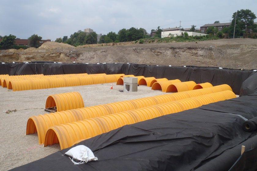
design specification Water Quality Volume (WQv) Rainfall
Underground detention basins are not suitable for WQv control.
OTHER SCM ATTRIBUTES
Channel Protection Volume (CPv) Yes
Detention / Retention Control Yes
Small Storm Local Flood Control
Typical SCM Footprint Size (percent of contributing drainage area)
Operation & Maintenance
(when properly maintained)
Overview
Underground detention basins are structural flood control facilities in the form of underground pipe systems or vaults. They are designed to provide detention and peak discharge control. Underground detention basins are popular in commercial and industrial areas due to the lack of surface footprint and versatility in configuration and size.
(Photo source: Philadelphia PA Water Department)
ADVANTAGES/BENEFITS
Ideal for use in highly urbanized areas where land is limited
Longevity is high with proper maintenance
SCM manufacturers/vendors can assist with proper siting and design
DISADVANTAGES/LIMITATIONS
Does not provide water quality control
Performance dependent on frequency of maintenance
Requires consideration of structural loads
DESIGN CONSIDERATIONS FOR LOCATION, SIZING, & COMPONENTS
Maximum contributing drainage area is 25 acres
Not appropriate for slopes greater than 15%
Minimum 2-foot separation from seasonally high-water table
Maximum depth to invert is 20 feet
Minimum pipe diameter is 36 inches
Requires consideration of structural loads for overburden and traffic/parking
Maintenance access location(s) must be thoughtfully considered
DESIGN CONSIDERATIONS FOR LONG-TERM PROTECTION
Underground design creates good protection from inadvertent damage
Protection measures primarily focus on safety and prevention of unwanted access
DESIGN CONSIDERATIONS FOR LONG-TERM MAINTENANCE
Primary routine maintenance activities will be trash and debris removal from inlets and removing sediment accumulation
Special equipment (vacuum trucks) and confined space entry certification may be required
Some SCM vendors/manufacturers can provide maintenance services
Northeast Tennessee Water Quality SCM Manual
5.12.1 General Description
Underground detention basins are typically utilized on sites where developable surface area is at a premium. Many design and material configurations are available, including box-shaped basins and round or semi-round “barrel” systems (see Figure 5.12.1.1). Materials used include reinforced concrete, corrugated metal pipe (CMP), as well as high density polyethylene (HDPE), and others. Many basins are commercially available from stormwater facility and manufactured treatment device (MTD) vendors. All methods serve as alternatives to surface dry detention for stormwater quantity control where there is not adequate land for a dry or wet detention basin. Basic storage design and routing methods are the same as for surface detention basins, except that a bypass (as opposed to an emergency spillway) is included for extreme flows.
5.12.1.1
Examples of Underground Detention Basins
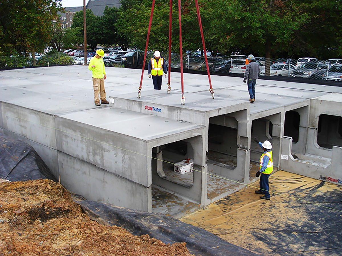
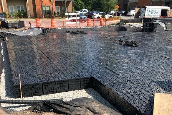
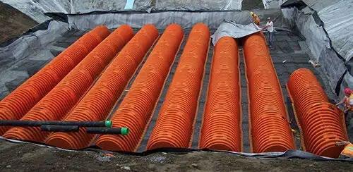
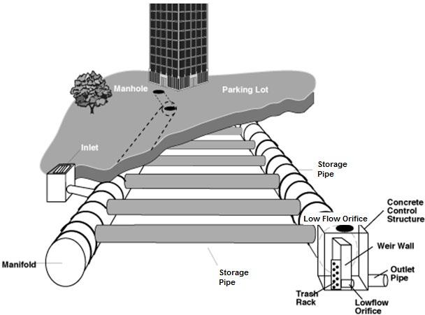
Underground detention basins are not capable of significant pollutant removal through extended detention. The potential for sediment resuspension during large storm events is high. However, some underground detention basin manufacturers advertise low impact development (LID) stormwater quality control through open bottom structures placed on a gravel bed, thus infiltrating the WQv. While this configuration is intriguing, a compacted subbase combined with potential difficulties with removal of accumulated sediment in the chambers are concerns. Thus, underground detention basins will not be approved for stormwater quality treatment. A separate SCM must be provided for this purpose. Since underground detention is used on urban sites that lack space for SCMs, smaller facilities such as bioretention areas, urban bioretention areas, Tier 2 manufactured treatment devices, and sand filters may be the best options for stormwater quality treatment where underground detention basins are employed.
Figure
Top left: underground storage vault made of concrete (Source: StormTrap); Top right: underground plastic grid storage (source: Exact Stormwater Management); Bottom left: underground pipe and chamber storage (source: NDSpro.com); Bottom right: depiction of a fully configured underground detention basin (Source: WDE, 2000)
Northeast Tennessee Water Quality SCM Manual
5.12.2 Design Applications
Underground detention basins can be designed in a variety of ways, but commonly fit into the following three categories. All serve as an alternative to surface detention for stormwater quantity control by providing temporary storage of stormwater and release at controlled rate(s)
Underground storage vaults are buried concrete, fiberglass, or polyethylene chambers
Underground pipe and chamber storage consists of perforated plastic or metal pipes, or pipe-like linear chambers, that are placed in a stone bed to provide more storage per unit volume. Various pipe dimensions and shapes can be used to optimize the storage volume to meet the specific site requirements.
Underground plastic grid storage consists of buried plastic structures that can be stacked and inter-connected to form various shapes and sizes. Grid systems can provide as much as 95% void space for storage of stormwater.
Because of their versatility, underground detention basins can be placed in a variety of locations. Typical locations for underground detention basins include the following.
Parking lots. Underground basins can be placed under parking lots in locations where space is limited. The underground unit(s) perform the same as surface detention basins.
Multi-use pervious areas on a site. Underground basins can be placed under open space areas on a site to provide stormwater management in locations without a lot of land for above ground detention
Retrofitting. Numerous options are available to retrofit detention areas in the urban landscape to increase buildable areas.
5.12.3 SCM Suitability
Use Table 5.12.3.1 to determine if an underground detention basin is suitable for the application being considered.
Table 5.12.3.1 Underground Detention Basin Suitability Factors
Stormwater Quality
Treatment
Channel Protection
Detention
Suitability by Land Use
Underground detention basins are not suitable to provide stormwater quality control.
Underground detention basins can be designed to satisfy local government channel protection standards.
Underground detention basins can be designed to satisfy local government peak discharge (flood) control requirements.
Privately owned underground detention basins are not allowed in the public right-of-way.
General suitability criteria by land-use type are as follows. See Chapter 3 (Standards, Methods, and SCM Selection) for more information.
*These policies do not preclude the use of underground detention basins on individually owned single family or multi-family residential lots. However, basins placed on residential lots will not be considered by the local government as suitable for compliance with local government stormwater management requirements due to the inherent difficulties in oversight and enforcement of long-term protection and maintenance requirements on residential lots
Northeast Tennessee Water Quality SCM Manual
5.12.4 SCM Location Requirements
Location constraints for underground detention basins are provided in Table 5.12.4.1.
Table 5.12.4.1 Underground Detention Basin Location Requirements
Physical Element
Requirement
Minimum setbacks, measured from the edge of the underground detention basin, are as follows:
Minimum SCM Setbacks
Stormwater Quality SCMs
Flow Avoidance
50 feet from private water supply well; if the well is down gradient from a land use with a high pollutant load (hotspot), then the minimum setback is 250 feet
Public water supply wells – see TDEC specifications.
50 feet from underground septic systems/leach field
Underground detention basins shall be located downstream of SCMs that provide stormwater quality control.
An underground detention basin shall not be located where it will receive continuous or dry weather inflows from springs, seeps, sump pumps, wash stations, or other sources.
Underground detention basins shall not be located above underground dry utility lines (electric, cable, and telephone) and water/wastewater infrastructure.
Utility Avoidance
Design professionals must consult the local utility to determine the horizontal and vertical clearance required between SCMs and dry and wet utility lines.
5.12.5 Design Requirements
The criteria provided in Table 5.12 5.1 shall be considered minimum standards and specifications for the design of underground detention basins and their contributing drainage areas. Beyond the policies provided herein, design professionals are encouraged to work with a commercial underground detention basin manufacturer/vendor to understand any additional design constraints and ensure proper selection and installation.
Table 5.12.5.1 Design Specifications for Underground Detention Basins
Design Element Specification(s)
Water Quality
Volume (WQv)
Controls for Waste & Other Pollutants
Underground detention basins do not provide treatment of the WQv.
Appropriate controls shall be included in the design of the contributing drainage area to the SCM to address any wastes and other pollutants (see Table 5.12.4.1 above) that are expected on the property after construction. Use the proposed land use as a guide to determine appropriate controls. Examples of such controls include, but are not limited to, dumpsters, trash cans, covered materials/waste storage areas, covered materials transfer areas, oil and grease waste controls, and pet waste stations.
Maintenance Access and Easements
Adequate maintenance access must be provided to each component of the underground detention basin, including access to each chamber/vault/pipe separately. Access openings can consist of a stand frame, grate, solid cover, removable panel, or other access mechanism. Vaults with widths of 10 feet or less should have removable lids.
A maintenance or drainage easement having a minimum width of 20 feet shall be provided from a driveway or public or private road. The easement shall extend to all components of the basin and, to the extent feasible, be designed to allow vehicles to turn around.
Northeast Tennessee Water Quality
Design Element
Drainage Area
Basin Volume & Drawdown
Minimum Depth to Water Table
Minimum Hydraulic Head
Structural Load Bearing
Specification(s)
Maximum contributing drainage area = 25 acres; larger drainage areas require multiple underground detention basins
Maximum slope of the contributing drainage area = 15%.
Underground detention basins designed for channel protection control shall discharge the CPv fully within 48 hours after the completion of a rain event. Use the orifice sizing guidance presented in Chapter 3 (Standards, Methods, and SCM Selection).
There are no restrictions on drawdown time for flood control storm events. Consult local government regulations regarding design storms and release rates.
Routing calculations must demonstrate that the basin’s storage volume is adequate for the design storms it is intended to control.
A minimum separation distance between the bottom of the basin and the elevation of the seasonally high-water table = 2 feet.
Soil borings shall be used to determine the seasonally high-water table. See Appendix F (Policies for Soil Infiltration Tests & Soil Borings) for soil boring requirements.
Minimum hydraulic head = 4 to 8 feet.
Structural load-bearing capacity of subsurface soils must be adequate to support the detention basin and stormwater volume at full capacity.
Underground detention basins built with vaults and tanks must meet structural requirements for overburden support and any additional loads expected (i.e., traffic, parked vehicles, etc.).
General:
Maximum depth from finished grade to basin invert = 20 feet
All construction joints must be provided with water stops.
Concrete vaults:
Physical Specifications
Material: minimum 3,000 psi structural reinforced concrete.
Cast-in-place wall sections must be designed as retaining walls
Pipes/Chambers:
Minimum diameter = 36 inches (3 feet)
Consult with manufacturer recommendations for additional physical specifications.
Pretreatment & Inlets
Outlet Structure & High Flow Bypass
Pretreatment for underground detention basins is recommended. Pretreatment reduces the amount of sediment discharged into the basin, thus decreasing its maintenance need. A hydrodynamic separator (i.e., Group 4) MTD is ideal for this purpose. Other options include a separate sediment sump or vault that can be easily accessed for removal of accumulated sediment. Sumps and vaults shall be sized to contain 0.1 inch of rainfall per impervious acre of untreated contributing drainage area.
In areas where litter, leaves, or other floatables are readily expected in stormwater to the underground detention basin, pretreatment should additionally include a basket, screen, grate, or other measure for debris capture.
The outlet structure shall consist of a weir, orifice, outlet pipe, combination outlet, or control structure. See Chapter 3 (Standards, Methods, and SCM Selection) for more information on outlet structure design.
Water shall not be discharged from an underground detention basin in an erosive manner. Riprap, plunge pools or pads, or other energy dissipaters must be located at the end of the outlet to prevent scouring and erosion.
Northeast Tennessee Water Quality SCM
Design Element Specification(s)
If the basin outlet discharges immediately to a channel that carries dry weather flow, care should be taken to minimize disturbance along the downstream channel and streambanks, and to reestablish a forested riparian zone in the shortest possible distance (if the downstream area is located in vegetated buffer).
A high flow bypass is required to safely pass flows greater than the maximum design storm required for detention by the local government. The bypass provides basin protection and release in the event of outlet structure blockage or mechanical failure. The bypass shall be located so that the downstream structures will not be impacted by emergency discharges.
Safety Features
A safety ladder (preferably permanently affixed) shall be provided for vaults deeper than 4 feet.
5.12.6 Design Procedure
Table 5.12.6.1 provides the design procedure for underground detention basins.
Table 5.12.6.1 Design Procedure
Evaluate underground detention basin feasibility.
1
Step 2
Use the feasibility criteria provided in Tables 5.12.3.1 and 5.12.4.1 to determine if an underground detention basin is feasible for the selected location. Consider especially whether it is appropriate for the proposed development based on the intended land use of the property, the maintenance burden, and assumptions or knowledge of how the property owner(s) will care for the basin after construction (e.g., self-maintenance, property/facilities management maintenance, landscape contractor). If possible, include the property owner(s) in SCM selection since they will be responsible for maintenance.
Determine underground detention basin location and preliminary geometry.
Ensure that there is adequate site area for installation of the underground detention basin, including maintenance access to the vault. Do this by creating a rough layout of its dimensions, taking into consideration existing trees, utility lines, and other obstructions.
Design the basin and outlet for CPv control.
Step 3
Step 4
If the basin will provide channel protection, set up a stage-storage-discharge relationship for the control structure for CPv. Size and determine the invert elevation of the CPv orifice to ensure that the CPv is stored for at least 24 hours within the basin.
Design the basin and outlet for flood control.
Set up a stage-storage-discharge relationship for the underground detention basin for the local government’s required detention design storms. Configure, size, and determine the invert elevations for the outlet(s) for the local government’s required design storm. Also, refine the sizing of the basin itself based on the stagestorage-discharge curve.
Design the emergency bypass.
Step 5
Step 6
Size emergency bypass and analyze safe passage downstream. Set the emergency bypass inlet elevation to a minimum of 0.1 feet above the water surface elevation for the maximum local design storm.
Design inlets and maintenance access.
See this design specification for more details. Ensure maintenance access is protected from unwanted entry.
Step Design Activity
Step
Northeast Tennessee Water Quality SCM Manual
5.12.7 SCM Maintenance on an Active Construction Site
SCM maintenance is regulated by local government ordinances from the moment they are installed. SCMs must also pass a final inspection prior to construction termination. This inspection will be performed to ensure they are constructed in accordance with the approved design, undamaged, and free of sediment and debris. Thus, SCM maintenance is good practice to ensure construction termination goes smoothly. Relevant policies are as follows:
The property owner is responsible for SCM maintenance. If the property is still an active construction site, these responsibilities may fall to the land disturbance permittee until the project receives final approval from the local government and/or a Certificate of Occupancy.
Property owners may have others, such as a site contractor maintain the underground detention basin on their behalf. However, the local government will hold the property owner responsible for ensuring it is maintained in proper operating condition (i.e., as designed and constructed) regardless of who performs maintenance activities.
Maintenance activities, which include ensuring proper operation of the SCM as designed and required SCM inspections, must begin immediately following installation of the underground detention basin.
Maintenance activities shall be performed in keeping with the Northeast Tennessee SCM Inspection and Maintenance Manual. Additional guidance on maintenance of newly installed underground detention basins located on active construction sites is provided in Table 5.12 7.1
Area or Component
Contributing Drainage Area
Underground Detention Area
Education
Post-Installation Maintenance Requirement
Keep the contributing drainage area clean. Sweep trash, debris, and sediment frequently so that it does not wash in the underground detention basin during a rain event.
The area should be fully stabilized before installation of the SCM. If it is not, prevent inflows to the SCM by blocking or using diversion measures, or establish and maintain EPSC measures to prevent sediment-laden water from discharging into the SCM
Cover stockpiles of construction and landscape materials to prevent their exposure to rainfall.
Remove sediment and debris from pretreatment and detention areas
Visually observe the SCM’s function after rain events; there should be no standing water within about 72 hours after a storm event, depending on the frequency of rainfall. If long-standing water is observed in the outlet structure(s) for blockages; make repairs if needed.
Alert onsite subcontractors and landscapers to the SCM and the following requirements:
No muddy vehicles or equipment in the drainage area to the underground detention.
No stockpiling of material and no exposed stockpiles in the basin’s drainage area.
No dumping of materials, lawn clippings, or landscape debris in the drainage area.
Repair areas of bare soil and erosion in the drainage area.
Block inlets prior to asphalt placement in the drainage area.
Remove sediment, trash, debris, and empty trash cans frequently.
5.12.8 References
ARC. Georgia Stormwater Management Manual Volume 2 Technical Handbook, 2016 Edition. Atlanta Regional Commission, 2016
Table 5.12.7.1 Maintenance Activities for Newly Installed Underground Detention Basins
5.13 Urban Bioretention
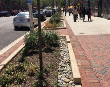
Overview
Urban bioretention areas are low impact development (LID) stormwater control measures (SCMs) designed to treat stormwater quality in highly impervious areas. Sometimes referred to as “stormwater planters”, these SCMs treat very small drainage areas. This makes them compact and thus useful for managing stormwater quality on zero-lot-line and highly developed properties. They are filled with an engineered soil mix for biofiltration. Trees, shrubs, and other herbaceous vegetation provide evapotranspiration and visual appeal. Urban bioretention areas are designed to address stormwater quality only, filtering water through the engineered soil mix and discharging it to the onsite stormwater drainage system via an underdrain.
ADVANTAGES/BENEFITS
Can be formed and sized to optimize the use of space
OTHER SCM ATTRIBUTES
Channel Protection
Detention
Small

Useful for any development context, including ultra-urban
Improves property value through attractive landscaping
DISADVANTAGES/LIMITATIONS
Maximum drainage area is 2,500 ft2
DESIGN CONSIDERATIONS FOR LOCATION, SIZING, & COMPONENTS
Must completely drain within 24-hours after a rain event
Maximum ponding depth of 6 inches prevents nuisance ponding
Minimum depth of 24 inches; minimum width of 18 inches
Minimum 2 feet separation from seasonally high water table
Underdrain required
DESIGN CONSIDERATIONS FOR LONG-TERM PROTECTION
Primary concerns are plant damage and soil compaction
Protect from entry by vehicles and heavy equipment
Suitable for a wide variety of protective designs (prickly shrub borders, curbing, decorative fencing, bench seating, etc.)
DESIGN CONSIDERATIONS FOR LONG-TERM MAINTENANCE
Primary routine maintenance activities will be inlet, pretreatment device, and plant bed cleaning and plant care (e.g., watering, weeding, pruning, mulching, leaf and landscape debris removal, plant replacement)
Consider installing pet waste stations to dissuade entry and use of SCM as a pet relief area
Provide trash cans in the drainage area
Select plants that can withstand occasional short-term inundation
5.13.1 General Description
Urban bioretention areas are small stormwater treatment areas designed to fit within tight landscape spaces (see Figure 5.13.1.1). What sets these SCMs apart from conventional bioretention areas is their small drainage areas, compact size, and vertical side walls. They must always include impermeable liners and underdrains. However, they treat stormwater in the same way a conventional Group 2 bioretention area does. Stormwater enters a landscaped bed planted with trees, shrubs, and other herbaceous vegetation, then soaks into the engineered soil mix below. Evaporation, plant transpiration, and biofiltration removes pollutants from the captured stormwater, which is then discharged to the onsite stormwater drainage conveyance system through the underdrain.
This design specification pertains to urban bioretention SCMs that are uniquely designed, sized, and constructed to fit the needs and aesthetics of the proposed land development. It does not address Group 2 LID-manufactured treatment devices (MTDs), which are similar in function but manufactured as standardized product lines in a range of sizes/capacities. See Section 5.7 (Manufactured Treatment Devices) for the design specifications pertaining to LID-MTDs.
5.13.1.1 Examples of Urban Bioretention Areas
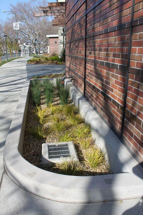
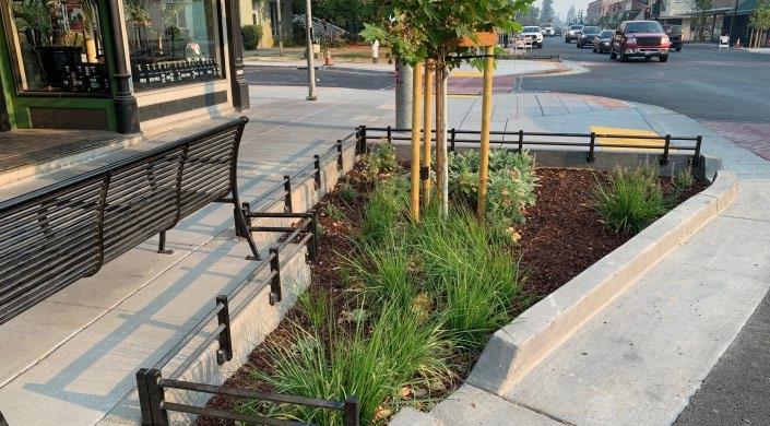
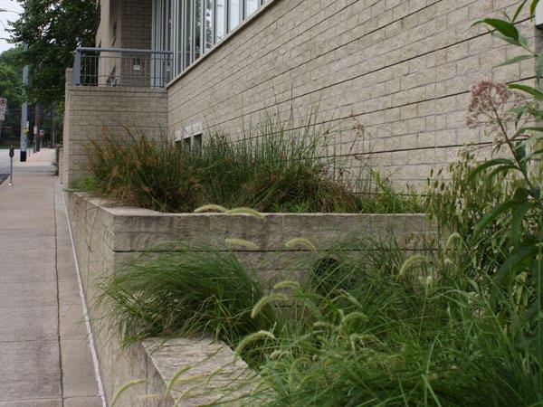
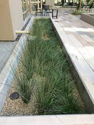
5.13.2 Design Applications
Urban bioretention SCMs are similar in function to conventional bioretention SCMs [see Section 5.1 (Bioretention Area)] except they are adapted to fit into “containers” within urban landscapes. They are becoming popular SCMs for urban
Figure
Left: An urban bioretention serves receives roof runoff through a downspout and serves as a decorative planter box; Upper Right: Urban bioretention areas manages runoff from the sidewalk and street in the City of Ukiah, CA (Source: Russian River Watershed Association); Lower middle: Urban bioretention boxes at the Tennessee Association of Realtors in Nashville TN (Metro Water Services); Lower Right: An urban bioretention area receives stormwater from the downspout of the adjacent building
streetscape or city street Right of Way (ROW). On privately owned properties, these highly versatile SCMs are appropriate for exterior planters adjacent to buildings, between buildings and sidewalks, or within outdoor congregational areas such as courtyards and plazas (see Figure 5.13.2.1).
Urban bioretention areas feature hard edges, often with vertical sides typically made of pre-cast or cast-in-place concrete Impermeable liners prevent water seepage, which is key to their flexibility in location. These SCMs always have an underdrain. These desired requirements ensure building foundations are not negatively impacted by water and adjacent areas do not experience nuisance water ponding during large events.
Urban bioretention areas are not intended for large commercial areas, nor should they be used to treat small sub-areas of a large drainage area such as a parking lot. Rather, these SCMs are intended to be incorporated into small, fragmented drainage areas such as shopping or pedestrian plazas within a larger urban development. Curbs, benches, and other decorative features are often placed along the perimeter of the SCM, providing both protection for the plants and soil and adding visual appeal.
A primary concern associated with the design of an urban bioretention area is its storage capacity. Each urban bioretention area must be able to manage the entire water quality volume (WQv). If this cannot be accomplished, due to site characteristics or constraints, consider using them in combination with other LIDSCMs, such as cisterns [Section 5.2 (Cistern)] or permeable pavement systems [Section 5.8 (Permeable Pavement System)]. These SCMs in particular partner well with urban bioretention areas and can easily supplement the stormwater management benefits provided by them.
5.13.3 SCM Suitability
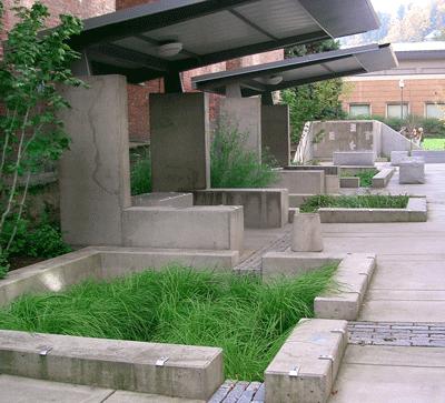
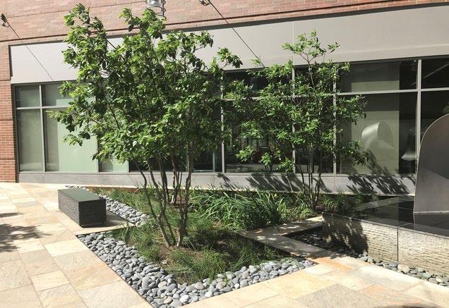

Use Table 5.13.3.1 to determine if an urban bioretention SCM is suitable for the application being considered.
Table 5.13.3.1 Urban Bioretention Suitability Factors
Factor
Stormwater Quality Treatment
Channel Protection
Suitability
Urban bioretention areas designed in keeping with the specifications established herein will satisfy local government stormwater quality treatment standards
Urban bioretention areas are not suitable for managing the channel protection volume (CPv) The SCM must be designed to bypass the CPv Detention
Urban bioretention areas are not suitable for peak discharge (detention) control, even for small design storms (the 2-year event). The urban bioretention area must be designed to bypass these flows.
Top: Urban bioretention areas outside Epler Hall at Portland State University (Source: Oregon Bureau of Environmental Services); Bottom: Urban bioretention areas in a plaza [Source: Clean Water Services (Water Resources Management Utility), Washington County, OR]
Figure 5.13.2.1 Urban Bioretention in Plazas
Pollutant Treatment
Capability
Treatment of Waste and Other Pollutants
Urban bioretention areas can be used to address following common stormwater pollutants1:
Not applicable
Suitability by Land Use
1 Georgia Stormwater Management Manual, Volume 2 Technical Handbook, 2016 Edition.
*Cadmium, copper, lead, and zinc
Urban bioretention areas shall not be used to treat the following pollutants:
Construction sediment/waste
Landscape storage or waste
Sewage, pet, and livestock waste
Medical waste
Household & commercial wastes
Hazardous wastes Gasoline, motor oils, greases, and other petroleum-based products Fats, oils & grease (from food preparation) Pesticides, fertilizers, herbicides Other byproducts and waste materials expected, based on the property’s land use
Privately owned urban bioretention SCMs are not allowed in the public right-of-way.
General suitability criteria by land-use type are as follows. See Chapter 3 (Standards, Methods, and SCM Selection) for more information.
5.13.4 SCM Location Requirements
Location constraints for urban bioretention areas are provided in Table 5.13 4.1
Table 5.13.4.1 Urban Bioretention Area Location Requirements
*These policies do not preclude the use of urban bioretention on individually owned single family or multi-family residential lots. However, urban bioretention placed on residential lots will not be considered by the local government as suitable for compliance with local government stormwater management requirements due to the inherent difficulties in oversight and enforcement of long-term protection and maintenance requirements on residential lots. Physical
Minimum setbacks are as follows:
10 feet from property lines
100 feet from private water supply wells.
Minimum SCM Setbacks
Risk Avoidance
400 feet from public water supply reservoirs (measured from edge of water)
1200 feet from public water supply wells.
100 feet from underground septic systems
At least 5 feet down gradient from underground utility lines.
Do not use urban bioretention areas in locations where their operation may create a risk for basement flooding, interfere with subsurface sewage disposal systems, or negatively affect other underground structures.
Flow Avoidance
Pollutant Hotspots
Utility Avoidance
An urban bioretention area shall not be located where it will receive continuous or dry weather inflows from springs, seeps, sump pumps, wash stations, or other sources.
Urban bioretention areas are required to have impermeable liners, therefore they can be used in pollutant hotspots and at locations where contaminated soil is known or suspected.
Urban bioretention areas shall not be located above underground dry utility lines (electric, cable, and telephone) and water/wastewater infrastructure.
Design professionals must consult the local utility to determine the horizontal and vertical clearance required between SCMs and dry and wet utility lines.
5.13.5 Design Requirements
The criteria provided in Tables 5.13 5.1 and 5.13 5.2 shall be considered minimum standards and specifications for the design of urban bioretention areas and their contributing drainage areas. These criteria shall be applied in the design of all Group 2 urban bioretention areas unless stated otherwise. Figure 5.13.5.1 is provided to identify the components described in the table.
Table 5.13.5.1 Design Specifications for the Contributing Drainage Area
Design Element
Specification(s)
Size Maximum contributing drainage area =2,500 ft2
Slope
Maximum slope of contributing drainage area = 6%; however, slopes that are as close to flat as possible are preferred to help ensure that stormwater is evenly distributed over the planting bed. If slopes exceed 6%, multiple urban bioretention areas can be constructed at varying elevations.
Controls for Waste & Other Pollutants
Appropriate controls shall be included in the design of the contributing drainage area to the SCM to address any wastes and other pollutants (see Table 5.13 3.1 above) that are expected on the property after construction. Use the proposed land use as a guide to determine appropriate controls. Examples of such controls include, but are not limited to, dumpsters, trash cans, covered materials/waste storage areas, covered materials transfer areas, oil and grease waste controls, and pet waste stations.
Figure 5.13.5.1 Primary Components of an Urban Bioretention Area (Cross-Section View)
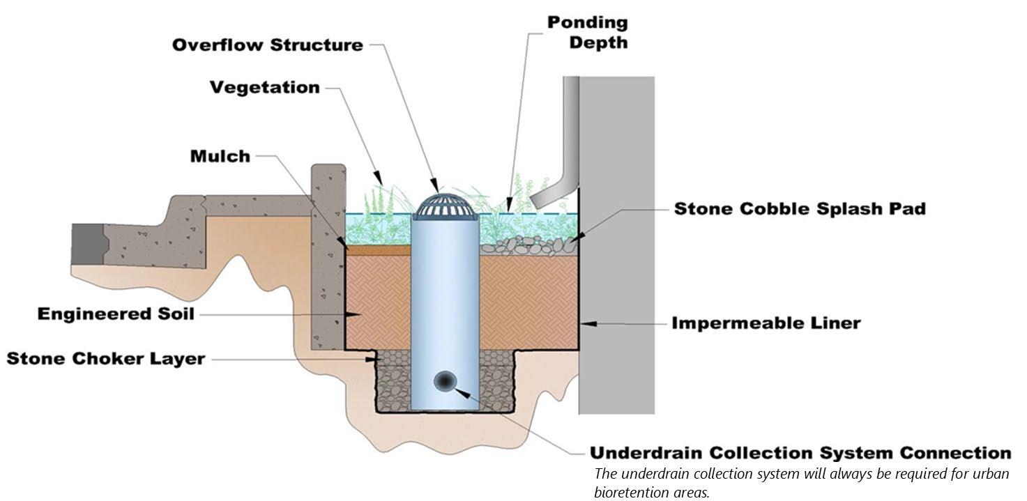
Table 5.13.5.2 Design Specifications for the Urban Bioretention Area
Design Element
Water Quality Volume (WQv)
Use in a Water Quality Treatment Train
Offline and Online Design Configuration
Specification(s)
Urban bioretention areas are a Group 2 SCM, therefore the water quality rainfall depths (P) for determination of WQv is: P = 1.25 inches:
Acceptable methods to determine WQv are presented in Chapter 3, Section 3.2.3 (Determining the WQv).
If the urban bioretention area can treat the entire WQv for its contributing drainage area, additional SCMs for stormwater quality treatment are not required in the contributing drainage area.
If the urban bioretention cannot manage the entire WQv for its contributing drainage area, it must be placed in a treatment train with another SCM. See treatment train policies and calculations in Chapter 3, Section 3.2.4 for treatment train policies and calculations.
Urban bioretention areas shall always be located upstream of other SCMs (e.g., detention basins designed for flood control, SCMs in a water quality treatment train, etc.).
An offline configuration is designed and constructed away from the main flow path for the drainage area, thus avoiding large flood flows. This configuration is the preferred configuration for urban bioretention areas that receive inflows from ground-level surfaces, such as a courtyard, as opposed to rooftops.
A flow splitter, diversion structure, or other means is used upstream of the SCM’s inlets to redirect the WQv from the main flow path to the SCM while still allowing larger flows to remain in the main flow path.
The diversion structure shall include a low-flow orifice, weir, or other hydraulic structure, sized to pass the peak discharge of the water quality peak discharge (Qwq) to the urban bioretention area.
Design Element
Maintenance Access and Easement
Inlets and Energy
Dissipation
Pretreatment
Overflow Structure
Specification(s)
An online configuration is designed and constructed so the main flow path for the drainage area passes through the urban bioretention area. This is a common configuration for urban bioretention areas that receive rooftop drainage, as the rooftop is the extreme upstream end of a flow path. However, it is not recommended for urban bioretention areas located at ground level and in a flow path for a large drainage area as there is a high potential for significant sediment accumulation and remedial maintenance. Thus, an online urban bioretention area is permissible only for drainage areas that are 100% impervious and have low potential for sediment and debris loads, such as drainage from a small building rooftop.
Flow regulators (flow splitters, diversion structures, and overflow structures) shall be designed in keeping with Sections 5.16 (Inlets, Energy Dissipation, and Pretreatment Measures) and 5.17 (Overflow Controls).
The entire urban bioretention area must be accessible for maintenance without requiring the entry of vehicles or heavy equipment in the urban bioretention area.
A maintenance easement to (and including) the urban bioretention area must be provided from a public roadway. The easement must be free of permanently affixed obstructions (e.g., trees, pools, fences without gates, permanent signs, etc.) to allow maintenance vehicles and equipment to safely pass.
Stormwater shall enter the urban bioretention area at non-erosive velocities (maximum of 5 ft/sec). Energy dissipation measures, such as rock aprons or stilling basins shall be provided for inflows exceeding 5 ft/sec. Such measures are common within urban bioretention areas that receive rooftop runoff, as depicted in Figure 5.13.5.2.
If used to receive non-rooftop drainage, consider employing a pea gravel diagram or equivalent level spreader device (e.g., concrete sills, curb stops, curbs with “sawteeth” cut into them) to intercept inflowing stormwater and distributing it evenly, as overland flow, across the urban bioretention area.
Pretreatment is not required for urban bioretention areas due to their small, highly impervious drainage areas that typically have low potential for sediment and debris loads.
An overflow structure that safely passes stormwater that exceeds the design volume (typically this will be the WQv) must be included in the design to prevent overfilling the SCM and flooding in adjacent areas. Small, offline urban bioretention areas may be excluded from this requirement depending on the design situation.
The overflow structure is typically a yard drain inlet with a debris/trash rack [see Figures 5.13.5.1 (above) and 5.13.5.2 (below)], though any number of conventional systems could be used. For example, a spillway that discharges to a nearby inlet for the onsite stormwater conveyance system is suitable.
The overflow structure shall bypass the underdrain and either discharge to the outlet pipe/channel for the urban bioretention area or directly to the onsite stormwater conveyance system (or a stabilized watercourse). Discharges from the overflow structure must be nonerosive (maximum of 5 ft/sec).
The elevation at which the overflow structure becomes operational must be set at the maximum ponding elevation (i.e., no more than 12 inches above the mulch layer).
Metal debris/trash racks are recommended over plastic to avoid UV degradation and the need for rack replacement (see Figure 5.13.5.2).
Flow Paths Maximum flow path lengths:
Design Element
Minimum Depth to Water Table
Minimum Hydraulic Head
Drawdown Time
Material
Surface Area and Geometry
Ponding Depth
Specification(s)
Pervious contributing drainage areas: 150 ft.
Impervious contributing drainage areas: 75 ft
For longer flow paths:
use multiple urban bioretention areas to break up the flow path, or
use a conventional bioretention area [Section 5.1 (Bioretention Area)] instead. Minimum separation distance (bottom of excavation to seasonally high-water table) = 2 feet.
Soil borings shall be used to determine the seasonally high-water table. See Appendix F (Policies for Soil Infiltration Tests & Soil Borings) for soil boring requirements.
Minimum hydraulic head = 2 feet.
The hydraulic head is the difference in the inflow elevation, including the design ponding depth, to the outflow elevation at the underdrain invert elevation at its downstream end.
The WQv shall fully discharge from the underdrain within 24 hours.
Urban bioretention areas can be constructed of stone, concrete, brick, or other durable material
Chemically treated wood is not allowed as it can leach toxic chemicals into the stormwater discharged through the underdrain.
Urban bioretention areas should be designed so that overflow drains away from buildings to prevent damage to building foundations
Minimum width (inside wall to inside wall) = 18 inches.
Walls must be vertical or near vertical
The geometry of the urban bioretention area shall be designed such that:
stormwater flowing into the SCM is distributed evenly across its entire surface area,
soil and vegetation within the SCM are not bypassed or short-circuited (e.g., incoming flow is diverted immediately to the underdrain).
Maximum surface ponding depth = 12 inches (above the mulch layer); 6 inches is recommended to avoid nuisance ponding.
The remaining rows specify the subsurface layers of the SCM, starting at the bottom.
Liner Layer
Underdrain & Internal Water Storage (IWS)
30 mil (0.030 inch) polyvinylchloride (PVC) impermeable liner.
Install the liner on the sides and bottom of the urban bioretention area to prevent damage to building foundations and other adjacent impervious surfaces
Minimum internal water storage (IWS) depth = 12 inches.
IWS (located in the engineered soil mix layer) shall be provided using an upturned elbow underdrain configuration. See Section 5.15 (Underdrains and Infiltration Sumps) for underdrain design requirements.
Double-washed AASHTO #8 stone or AASHTO #89 pea gravel.
Stone Choker Layer
Engineered Soil Mix Layer
Layer depth = 3 inches; placed above the underdrain’s stone jacket
Minimum depth of engineered soil mix layer = 24 inches (includes the required minimum depth of 12 inches for IWS); beyond this minimum, the design depth is determined by the design volume (typically this will be the WQv), the design IWS (minimum is 12 inches), the SCM urban bioretention geometry, and plant needs for establishment and long-term root growth.
The engineered soil mix shall be a homogenous mix and meet the standards in the following two tables to provide adequate infiltration, nutrient uptake, and plant support.
Design Element
Material
Medium to coarse washed sand:
Specification(s)
70-85%
Particle size: 0.050 to 2.0 mm
AASHTO T88 Standard Method of Test for Particle Size Analysis of Soils Clean, fine soil:
Silt + clay 10 to 20%, with clay content less than 10%
Clay particle size: < 0.002 mm
Silt particle size: 0.002 to 0.050 mm
5 to 8%
Organic Matter
*Animal or poultry manure, at any stage of composition, shall not be used for organic matter content
Parameter
pH
Magnesium
Phosphorus* (as phosphate P205)
Potassium (K20)
Soluble Salts
AASHTO T194 Standard Method of Test for Determination of Organic Matter in Soils
Specification
5.5 to 7.5
Minimum 32 parts per million (ppm)
Maximum 60 ppm as plant available phosphorus
Minimum 78 ppm
Maximum 500 ppm
The volume of engineered soil mix specified and placed shall be based on 110% of the required volume for the SCM to account for settling just after mix placement in the SCM.
Assume an infiltration rate of 2 inches per hour for the engineered soil mix when determining the ponding depth and media depth.
Topsoil is not necessary as the engineered soil mix described above will support plant life. Minimum depth of mulch layer = 4 inches.
The mulch shall be clean, undyed, triple-shredded, hardwood mulch, free of weeds and debris. Where mulch is not used, native ground cover or washed, decorative landscape stone having a size large enough to withstand the maximum inflow velocity of 5 ft/sec.
The following materials are PROHIBITED for use as a mulch layer.
Shredded pine bark (will float and clog outlets and downstream stormwater systems).
Un-composted bark mulch, lawn and landscape clippings, and immature composted materials (will alter oxygen and nitrogen content of underlying soil)
Rubber mulch or “crumb rubber” (can release pollutants and clog outlets and downstream stormwater systems).
Plastic sheeting of any kind, as it can disintegrate from sun exposure
Planting Bed See Section 5.13.7
Mulch Layer
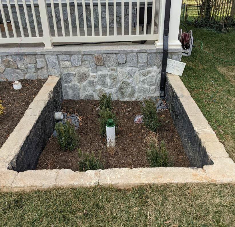
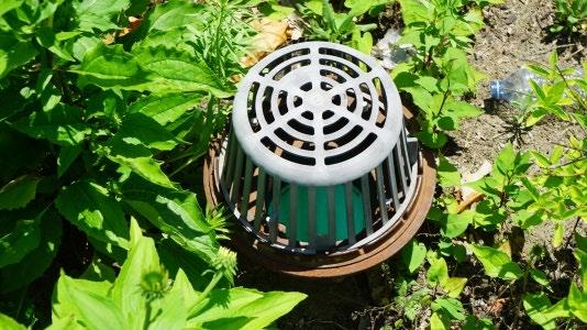
5.13.6 Design Procedure
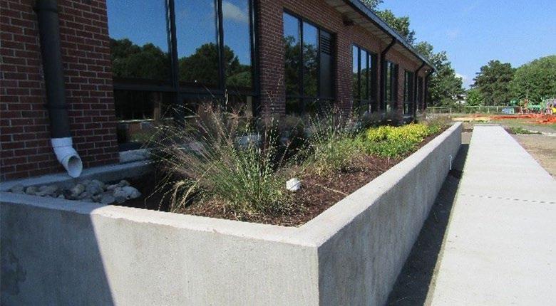
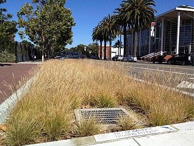
Table 5.13.6.1 provides the design procedure for an urban bioretention area.
Table 5.13.6.1 Design Procedure
Step
Step 1
Evaluate urban bioretention area feasibility.
Design Activity
Step 2
Top left: The inlet pipe, splash pad, and overflow device are visible in this newly installed urban bioretention area (Source: Demarr Engineering). Top right: A large stormwater planter manages roof drainage at a school in Newport News, VA (Timmons Group); Lower left: The grayish color of this plastic inlet grate indicates UV degradation. Metal is preferred (City of Fort Wayne, IN); Lower right: A metal grate on an overflow in an Emeryville, CA urban bioretention SCM (wiki.sustainabletechnologies.ca)

Use the feasibility criteria provided in Tables 5.13 3.1 and 5.13 4.1 to determine if an urban bioretention area is feasible for the selected location on the land development site. Consider especially whether it is appropriate for the proposed development based on the intended land use of the property, the maintenance burden, and assumptions or knowledge of how the property owner(s) will care for the urban bioretention area after construction (e.g., self-maintenance, property/facilities management maintenance, landscape contractor). If possible, include the property owner(s) in SCM selection since they will be responsible for maintenance.
If an urban bioretention area is determined to be feasible and appropriate for the proposed development, create a rough layout of its dimensions, taking into consideration existing trees, utility lines, and other obstructions to ascertain if it will fit into the desired space, given its general design requirements.
Calculate the design storage volume (DSv) for the contributing drainage area.
Typically, the DSv = WQv, unless the urban bioretention area cannot manage the entire WQv or will be used to control a volume larger than the WQv for a higher level of stormwater treatment
Figure 5.13.5.2
Step Design Activity
Use one of the calculation methods explained in Chapter 3, Section 3.2.3 (Determining the WQv) to calculate WQv.
Determine the minimum surface area of the urban bioretention area. �������� = ������������ × �������� ���� × ��������� + �������� � × ��������
where:
Af = surface area of the ponding area (ft2)
Step 3
Step 4
Step 5
Step 6
DSv = design storage volume (typically this will be the water quality treatment volume) (ft3)
df = planting media depth (ft)
k = coefficient of permeability of planting media (ft/day) (use one [1] ft/day for the engineered soil mix)
hf = average height of water ponding above urban bioretention bed (ft)
tf = planting media design drain time (days) (tf = 1)
Size the overflow structure and any flow diverters or regulators.
See Sections 5.16 (Inlets, Energy Dissipation, and Pretreatment Measures) and 5.17 (Overflow Controls).
Design the underdrain.
See Section 5.15 (Underdrains and Infiltration Sumps).
Design the vegetation and protection measures.
The vegetation design shall be in accordance with the vegetation design requirements provided in Table 5.13.6.1. Use guidance found in Section 5.13.9 (below) to design protection measures.
5.13.7 Vegetation Design Requirements
Plants are critical to urban bioretention area performance and function. Plants filter and transpire stormwater, providing both pollutant removal and stormwater volume reduction. They also maintain the health and permeability of the engineered soil mix by preventing erosion, creating root space, and providing organic matter for nutrient replenishment. Finally, the plants are the primary visual attribute of the urban bioretention area and thus enhance the landscape.
The importance of plants to urban bioretention area function means they, like any SCM component, have design, installation, and maintenance specifications. Table 5.13.7.1 provides the vegetation specifications for urban bioretention areas.
Table 5.13.7.1 Vegetation Design Specifications
Vegetation Design Element
Minimum Coverage
Specification(s)
A minimum of 75% of the urban bioretention surface area must be covered by vegetation The remaining areas must be covered by mulch (see mulch specifications in Table 5.13 5.2) or decorative landscape stone having a size large enough to withstand the maximum inflow velocity of 5 ft/sec. Areas of bare soil are not allowed.
The minimum coverage requirement must be achieved within the first growing seasons (March through November) after installation, and then maintained thereafter.
Vegetation Design
Specification(s)
Plant Survival Plant replacement is required when the minimum coverage goal of 75% is not achieved.
Plants and trees selected for an urban bioretention area must be resistant to cycles of drought and inundation, as both conditions will occur.
Non-native, flowering annuals are often not well suited to such conditions, and thus can require a lot of care. For guidance on appropriate plant species, consult a plant and landscape expert, such as a landscape architect, local nursery, or Master Gardener from the Tennessee Extension Master Gardener program. (https://mastergardener.tennessee.edu/)
Plant Selection
Trees must be appropriate for the SCM location, with their mature height taken into account if located near a building or beneath existing overhead utility lines. Smaller species with compact root systems are preferable to avoid root damage to subsurface components. Evergreens are preferred as seasonal leaf drop can clog inlets, outlets, and the mulch layer.
Trees are not recommended for urban bioretention areas located adjacent to buildings, due to the potential for damage to the impermeable liner and underdrain from roots.
Native plant species better suited to local hydrologic conditions are recommended.
Plants suitable for United States Department of Agriculture Plant Hardiness Zoned 6b and 7a (depending on your zip code) are recommended.
Consider future maintenance needs of vegetation when designing the urban bioretention area. The level of plant care needed to maintain the landscape should influence plant selection to minimize care needs as much as possible
Compliance with the vegetation standards set forth in Table 5.13 7.1 shall be shown in a vegetation plan that is included with the water quality management plan (WQMP). Plan preparation requirements are below.
The plan must be prepared by a professional qualified in landscape design by their education or experience.
The plan shall include one or more labeled plans/details (to scale) showing the plants to be installed, their numbers, and locations. Plan notes showing a plant schedule and installation instructions are encouraged. This additional information allows both the plant installer at the time of construction, as well as the person(s) responsible for maintenance of the SCM after construction, to understand the original vegetation design and its compliance with the minimum standards.
Landscaped SCMs may not be recognized under the local government’s codes as property landscaping. Therefore, additional requirements for property landscaping may apply.
5.13.8 Protection Design Guidance
SCMs designed for stormwater quality purposes must be maintained in keeping with the approved SCM design for the life of the land development 1 . Design professionals can assist property owners with this requirement by including protective features in and around SCMs to limit the potential for damage by external factors. Often, the landscape and impervious features around an SCM can be tailored to its specific needs, and therefore used to protect its critical components. For urban bioretention areas, protection is especially important for the planting bed. Entry by vehicles, heavy equipment, and pedestrians can damage plants, compact the engineered soil mix, damage the overflow structure, and potentially deform or crush the underdrain collection system. Trash and pet waste are also a common problem. However, urban bioretention areas are especially well-suited to a variety of protection methods that can enhance the property’s landscape
aesthetic or impervious surface function. Protection methods that work well are listed in Table 5.13.8.1. Examples of urban bioretention protection are shown in Figure 5.13 8.1
Table 5.13.8.1 Urban Bioretention Protection Measures*
Natural fencing such as vegetation borders/screens (woody/prickly shrubs or tall grass)
Dense vegetation throughout the practice
Pedestrian benches on the perimeter
Decorative fencing
Curbs or curb blocks
Hardscaping, such as curbing, block edging, cobbles
Educational or directive (e.g., no pets) signs
Pet waste stations and trash cans near the SCM
*The list presented in the table is not exhaustive. There may be other possible protection measures.
Figure 5.13.8.1 Examples of Protective Landscaping
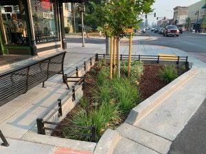
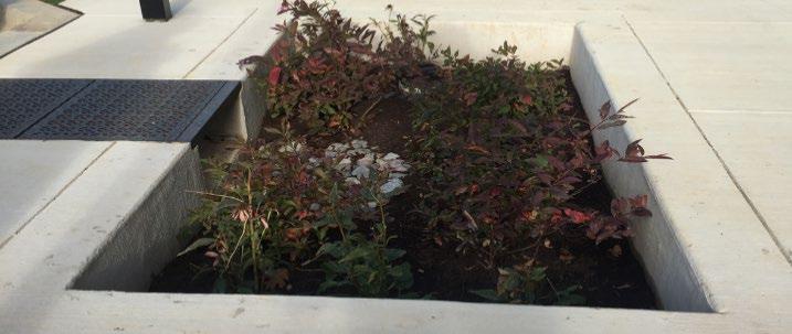
Decorative fencing, a bench, and curbs protect this newly installed bioretention area from foot traffic (Russian River Watershed Association); Top Right: Small recessed urban bioretention cells discourage entrance by pedestrians and pets. However, the drop curb design may present a safety hazard for some local governments. Fencing or curbs are highly recommended. (City of Rockville, MD); Bottom right: curbs and dense vegetation protect this large urban bioretention area that receives roof runoff (Source: Center for Watershed Protection)
5.13.9 Installation Requirements
The information in Table 5.13.9.1 provides a typical construction sequence to properly install urban bioretention areas. These steps may be modified to reflect different applications or site conditions. Installation practices shall be shown in the EPSC and WQMP plans, as appropriate for the proposed land development.
Table 5.13.9.1 Installation Steps
Step
Step 1
Requirement
Check the installation location for existing utilities prior to construction.
REQUIRED: Site construction shall be sequenced such that the urban bioretention area is installed only after the area draining to it has been fully and permanently stabilized. If this is not feasible, block the inlets to the area until the contributing drainage area is fully and permanently stabilized.
Left:
Step
Step 2
Requirement
Supervision during construction is required to ensure the urban bioretention area is constructed/installed in accordance with the approved EPSC and WQMP plans. The design professional or a designee under their supervision must inspect the urban bioretention area at critical stages of construction. Examples of critical stages of underdrain installation and connection to the onsite stormwater conveyance system and final inspection. This ensures that the contractor’s interpretation of the plan is consistent with the design professional’s intentions and allows the design professional to certify (in the as-built plan) that the urban bioretention area is built in keeping with the permitted plan.
Construction sites can have many different contractors responsible for different portions of the site or aspects of construction. Therefore, subtle differences in site grading, drainage, and paving elevations from those identified in the design, or relative to different areas/aspects of construction, can affect the hydraulics of the proposed urban bioretention area. The following practices should be done prior to construction to ensure the approved design is still valid:
During the preconstruction meeting, review and confirm that the actual boundaries of the urban bioretention area’s contributing drainage area and inlet elevations conform with the approved design.
Any changes that result from the preconstruction meeting must be shown as a revision to the WQMP and resubmitted to the local government for approval.
Step 3 Install inlet protection and/or erosion prevention and sediment control measures as indicated in Step 1.
Step 4
Step 5
Excavate the urban bioretention area to its appropriate design depth and dimensions. Remove rocks and trim roots that enter the excavation area.
Install the urban bioretention area walls (and bottom if full enclosure is desired).
Install the impermeable liner on the sides and bottom with a minimum 12 inch substantial overlap at the seams.
Place the required depth of stone on the bottom (per underdrain design specifications), then install the underdrain, its connection to the onsite drainage system, and the outlet structure (if a standpipe is attached to the underdrain). Install any observation wells needed.
Carefully place the top of the underdrain’s stone jacket.
Place the stone choker layer to its design depth.
Apply the engineered soil mix in 12 inch lifts until the desired top elevation of the urban bioretention area is achieved. A rule-of-thumb is to apply 110% of the design volume of soil to account for settling that will occur.
Step 6
Wait a few days for settlement and add or remove additional engineered soil mix as needed to achieve the design elevation.
Note: The batch receipt confirming the source of the engineered soil mix must be included with the Record Drawing.
Step 7 Install temporary or permanent irrigation measures, if included in the design.
Install plants as shown in the vegetation plan (see Section 5.13.7).
Step 8
Install the surface cover (i.e., mulch, river stone, or turf). If coir or jute matting will be used in lieu of mulch, the matting will need to be installed prior to planting, and holes or slits will have to be cut in the matting to install the plants.
Step 9 Install SCM protective measures.
Step 10
Erosion/sediment control devices and inlet blockages can be removed from the inlets if the drainage area to the urban bioretention area is fully and permanently stabilized.
Step
Step 11
Requirement
If the area draining to the urban bioretention cell includes newly installed asphalt, the erosion/sediment control devices or inlet blocks should remain in place for at least three storm events after asphalt installation. A substantial amount of fine particles and grit are discharged from newly installed asphalt during the first several storms that produce stormwater after installation. Maintenance will be required to remove the particles and grit if erosion/sediment control devices are removed too early.
Maintain the urban bioretention area in keeping with Section 5.13.10 below.
Prepare the Record Drawing and submit it to the local government for review and approval with the engineer’s as-built certification before a final or temporary Certificate of Occupancy can be obtained.
Advise the landowner (i.e., the person(s) taking ownership of the property immediately after its development) of the presence of the urban bioretention area and provide them with a copy of the property’s Record Drawing and SCM maintenance plan. The plan must clearly show the location of the urban bioretention area on the property and list the activities (and their frequencies) necessary for its proper maintenance.
5.13.10 SCM Maintenance on an Active Construction Site
SCM maintenance is regulated by local government ordinances from the moment they are installed. As well, SCMs must also pass a final inspection prior to construction termination. This inspection will be performed to ensure they are constructed in accordance with the approved WQMP, undamaged, and free of sediment and debris. Thus, SCM maintenance is good practice to ensure construction termination goes smoothly. Relevant policies are as follows:
The property owner is responsible for SCM maintenance. If the property is still an active construction site, these responsibilities may fall to the land disturbance permittee until the project receives final approval from the local government and/or a Certificate of Occupancy.
Property owners may have others, such as a site contractor or landscaping company, maintain the urban bioretention area on their behalf. However, the local government will hold the property owner responsible for ensuring it is maintained in proper operating condition (i.e., as designed and constructed) regardless of who performs maintenance activities.
Maintenance activities, which include ensuring proper operation of the SCM as designed and required SCM inspections, must begin immediately following installation of the urban bioretention area.
Maintenance activities shall be performed in keeping with the Northeast Tennessee SCM Inspection and Maintenance Manual. Additional guidance on maintenance of newly installed urban bioretention areas located on active construction sites is provided in Table 5.13.10.1.
Table 5.13.10.1 Maintenance Activities for Newly Installed Urban Bioretention
Areas
Keep the contributing drainage area clean. Sweep trash, debris, and sediment frequently so that it does not wash in the basin during a rain event.
The area should be fully stabilized before installation of the SCM. If it is not, prevent inflows to the SCM by blocking or using diversion measures until the contributing drainage area is fully stabilized. Stabilize the area as soon as possible to prevent the discharge of sediment to the SCM
Cover stockpiles of construction and landscape materials to prevent their exposure to rainfall.
Area or Component
Urban Bioretention Area
Education
Post-Installation Maintenance Requirement
Ensure SCM plants are watered and growing as expected.
Remove and replace diseased, dying, or dead plants as soon as they are noticed.
Clean the inlet(s) and planting bed frequently, removing trash, debris, and accumulated sediment
Ensure vehicles, equipment, and people are not allowed in the urban bioretention area. Evidence of unwanted entry may look like tire tracks or footprints; mulch or stone displacement, or damage to components or vegetation; immediately determine and eliminate the cause and repair the area.
Consider installing temporary fencing if the area isn’t fenced already.
Visually observe the SCM’s function after rain events; there should be no standing water within 24hours after a storm event, depending on the frequency of rainfall. If long-standing water is observed:
Inspect underdrain’s outlet and overflow device looking for standing water indicative of a blockage or damage; make repairs if needed.
If underdrain/outlet blockages and damage can be ruled out, then the engineered soil mix may be clogged. This repair requires soil removal, cleaning of the stone, underdrain, and outlet structure, and reinstallation of all the urban bioretention area layers; consult the design engineer.
Inspect the urban bioretention area for erosion or significant sediment buildup; immediately determine and eliminate the cause and repair the area.
Alert onsite subcontractors to the SCM and the following requirements:
No muddy vehicles or equipment in the drainage area to the SCM.
No stockpiling of material in the SCM and no exposed stockpiles in the SCM’s drainage area.
Block inlets prior to asphalt placement in the drainage area.
Remove sediment, trash, debris, and empty trash cans frequently.
Advise landscaping subcontractors on proper protection and maintenance of the urban bioretention area, especially the following:
No heavy equipment (hand tools only)
No dumping of lawn clippings or landscape debris in the SCM.
Plant maintenance needs/requirements (see above)
Mulch specifications (i.e., clean, undyed, natural hardwood mulch).
5.13.11 References
ARC. Georgia Stormwater Management Manual Volume 2 Technical Handbook, 2016 Edition. Atlanta Regional Commission, 2016
5.14 Water Quality Basin
design specification
Overview
P = 2.5 inches or the first 75% of the volume of the 1-yr, 24-hr storm, whichever is less
SCM Group: 3
Water quality basins are large SCMs that have a permanent pool of water. They provide water quality control in the pool primarily through pollutants settling to the bottom of the basin . Flood control is provided by detaining stormwater above the permanent pool.
ADVANTAGES/BENEFITS
Can satisfy multiple stormwater design standards
Can be part of an amenity area for development(s) served
High community acceptance if maintained
DISADVANTAGES/LIMITATIONS
Potential for thermal impacts/downstream warming
Dam height restrictions for high relief areas
DESIGN CONSIDERATIONS FOR LOCATION, SIZING, & COMPONENTS
Minimum contributing drainage area of 25 acres for wet and wet ED basins; 10 acres for micropool ED basin
Minimum length to width ratio for the basin is 1.5:1
Maximum depth of permanent pool is 8 feet
Side slopes cannot exceed 3:1 (h:v) on one side of the basin to facilitate access; Slopes as steep as 2:1 will be allowed for other areas, with proper stabilization
A liner may be required to sustain a permanent pool.
Sediment forebay(s) are required for pretreatment at each inlet
Multi-stage riser outlet structure is necessary
Safety measures must be included
DESIGN CONSIDERATIONS FOR LONG-TERM PROTECTION
Primary concerns are slope stability and outlet structure clogging and damage
Suitable for a wide variety of protective and aesthetic designs (vegetated borders, hardscaping, fencing, signage, etc.).
DESIGN CONSIDERATIONS FOR LONG-TERM
MAINTENANCE
The potential for adequate long-term maintenance can increase when the SCM is designed and constructed as an attractive feature or amenity of the development
Primary routine maintenance activities will be removing debris from inlets and the outlet structure, forebay cleaning, and plant care (e.g., removing invasive vegetation, repairing and revegetating eroded areas, etc.).
Consider permanent signs to prohibit swimming
If part of a pedestrian area or trail, consider permanent signs and provide pet waste stations with trash cans
Consider geese deterrent design measures
Northeast Tennessee Water Quality SCM Manual
5.14.1 General Description
Water quality basins are stormwater retention basins that are designed to maintain a permanent pool of water throughout the year. They can be created by excavating an existing natural depression or through the construction of embankments. Depending on design, a single water quality basin can meet multiple stormwater design standards, functioning as follows:
Water Quality Volume (WQv) – In a water quality basin, runoff from each storm is detained as, or above, the permanent pool until it is displaced by inflows of stormwater from the next storm. While the stormwater is in the basin, suspended sediments are removed via gravitational settling. In turn, other pollutants can be removed via settling or biological uptake by basin flora and fauna. The permanent pool also serves to protect deposited sediments from resuspension.
For stormwater quality control, water quality basins must be designed for extended detention (minimum 24hours) of the water quality WQv. If the basin cannot be designed to detain the entire WQv, the basin must be placed in a treatment train with an upstream SCM or exchanged with a SCM that can treat the entire WQv .
As a Group 3 SCM, the WQv is based on 2.5-inch rainfall or 75% of the runoff volume from the 1-year, 24-hour storm event (whichever is less) at the location of the development.
Channel Protection Volume (CPv) – The channel protection standard reduces or eliminates streambank incising and instream sedimentation resulting from high frequency storm events. The standard requires extended detention of the CPv (i.e., the runoff volume from the 1-year, 24-hour storm) for no less than a 24-hour period. This requirement is nearly the same as the WQv standard. Thus, basins that treat the entire WQv will not require additional design for CPv control. See Chapter 3 (Standards, Methods, and SCM Selection) for more information.
Flood Protection – Water quality basins can provide stormwater control for water quantity by detaining stormwater from large storm events to prevent flooding of adjacent and downstream properties. Additional temporary storage (live storage) is created above the permanent pool for this purpose, and a multi-stage outlet riser allows discharge of runoff at design flow rates.
5.14.2
Design Applications
There are several variants of water quality basin design, the most common of which include the water quality basin, the wet extended detention basin, and the micropool extended detention basin. In addition, multiple water quality basins can be placed in series or parallel to increase performance or meet site design constraints. Below are descriptions of each design variant:
Wet Basin – Wet basins are constructed with a permanent (dead storage) pool of water equal to the WQv. Stormwater displaces the WQv already present in the pool. Temporary storage (live storage) can be provided above the permanent pool elevation for flood control.
Wet Extended Detention (ED) Basin – A wet extended detention basin is a wet basin where the WQv is split evenly between the permanent pool and extended detention (ED) storage provided above the permanent pool. During storm events, water is detained above the permanent pool and released over 24 hours. This design has similar pollutant removal to a traditional wet basin but consumes less space. Temporary storage (live storage) can be provided above the permanent pool elevation for flood control.
Micropool Extended Detention (ED) Basin –The micropool extended detention basin is a variation of the wet ED basin where only a small “micropool” is maintained at the outlet to the basin. The outlet structure is sized to detain the WQv for 24 hours. The micropool prevents resuspension of previously settled sediments and prevents clogging of the low flow orifice. Temporary storage (live storage) can be provided above the permanent pool elevation for flood control.
Northeast Tennessee Water Quality SCM Manual
Multiple Basin Systems – Multiple basin systems consist of constructed facilities that provide WQv and flood control storage in two or more cells. The additional cells can create longer pollutant removal pathways and improved downstream protection.
Figure 5.14.2.1 shows several examples of water quality basin variants.
Figure 5.14.2.1
Examples of Water Quality Basins
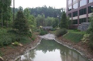
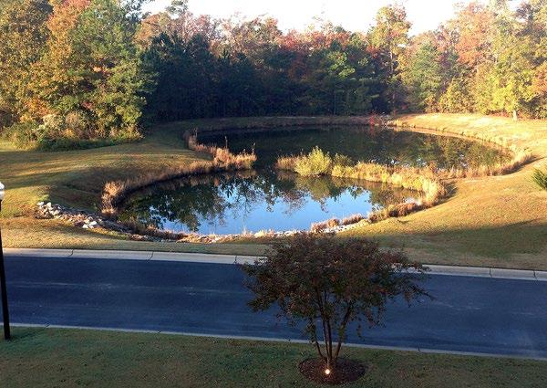
5.14.3 SCM Suitability
Use Table 5.14.3.1 to determine if a water quality basin is suitable for the application being considered.
Table 5.14.3.1 Water Quality Suitability Factors
Factor
Stormwater Quality Treatment
Channel Protection
Detention
Suitability
Water quality basins designed in keeping with the specifications established herein will satisfy local government stormwater quality treatment standards
Water quality basins sized to manage the entire WQv, as described in Chapter 3 (Standards, Methods, and SCM Selection), will meet the CPv standard without the need for additional design. If the basin cannot retain the entire WQv, then the CPv standard is not met.
Water quality basins can be designed to satisfy local government peak discharge (flood) control requirements.
Top left: A wet basin located at the Risteau at Rockland in Baltimore County, MD; Top right: A wet ED basin (location and source unknown); Bottom right: A multiple basin system in Brunswick County, NC (Source: NC State Extension); Bottom left: A micropool ED basin at Grant Ranch in Denver, CO (Source: Mile High Flood District)
Northeast Tennessee Water Quality SCM Manual
Factor Suitability
Water quality basins can be used to address the following common stormwater pollutants:
Pollutant Treatment Capability
Treatment of Waste and Other Pollutants
1 – If designed for the WQv specified in Tennessee Department of Environment and Conservation Rule 0400-40-10-.04
2 – Georgia Stormwater Management Manual, Volume 2 Technical Handbook, 2016 Edition.
3 – Cadmium, Copper, Lead, and Zinc
4 – If waterfowl populations are not in residence
Water quality basins shall not be used to treat the following pollutants:
Construction sediment/waste
Landscape storage or waste
Sewage, pet, and livestock waste
Medical waste
Household & commercial wastes
Hazardous wastes
Gasoline, motor oils, greases, and other petroleum-based products
Fats, oils & grease (from food preparation)
Pesticides, fertilizers, herbicides
Other byproducts and waste materials expected, based on the property’s land use
Privately owned water quality basin SCMs are not allowed in the public right-of-way.
General suitability criteria by land-use type are as follows. See Chapter 3 (Standards, Methods, and SCM Selection) for more information.
Suitability by Land Use
*These policies do not preclude the use of water quality basins on individually owned single family or multi-family residential lots. However, basins placed on residential lots will not be considered by the local government as suitable for compliance with local government stormwater management requirements due to the inherent difficulties in oversight and enforcement of long -term protection and maintenance requirements on residential lots
5.14.4 SCM Location Requirements
Location constraints for water quality basins are provided in Table 5.14.4.1
Table 5.14.4.1 Water Quality Basin Location Requirements
Minimum setbacks, measured from the outer limit of the basin, are as follows:
15 feet from habitable structures. The first-floor elevation for any structure adjacent to the basin shall have an elevation no lower than 1 foot above the top of the berm.
50 feet from private water supply wells.
50 feet from a septic tank/leach field.
TDEC specified distance per designated category from public water supply reservoirs.
Water quality basins shall not be located where they will receive inflows from sump pumps, wash stations, or other non-stormwater discharges.
Flow Avoidance
Water quality basins shall not be located in a stream or any other navigable waters of the United States, including natural (i.e., not constructed) wetlands. Where an appeal or variance of this policy is desired, the property owner must obtain coverage under a Section 404 permit under the Clean Water Act and/or an Aquatic Resource Alteration Permit (ARAP) and provide proof of such coverage with the Water Quality Management Plan.
Utility Avoidance All utilities shall be located outside of the water quality easement.
5.14.5 General Design Information
Figures 5.14.5.1 , 5.14.5.2, 5.14.5.3, and 5.14.5.4 show schematics of the four different types of water quality basins. The figures are adapted from original schematics developed by the Center for Watershed Protection.
5.14.5.1
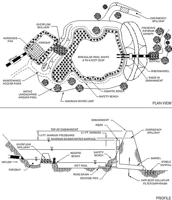
Figure
Schematic of a Wet Basin
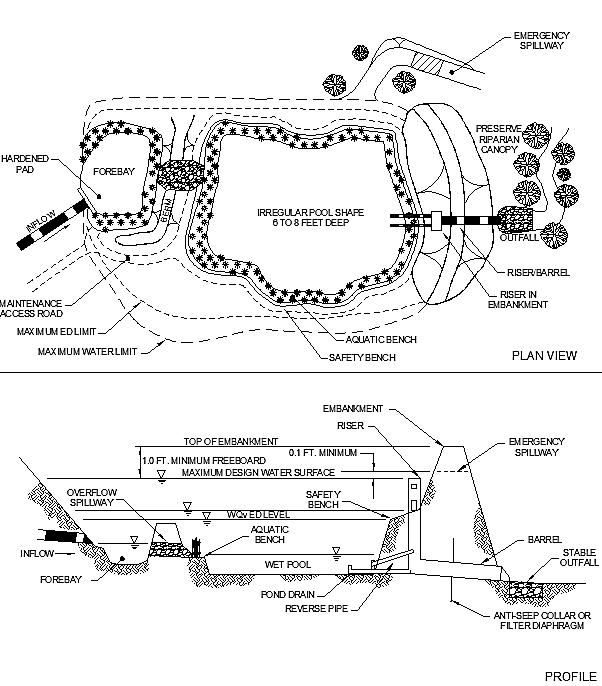
Figure 5.14.5. 2 Schematic of a Wet ED Basin
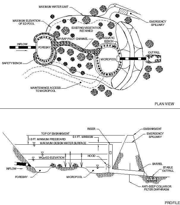
Figure 5.14.5. 3 Schematic of a Micropool ED Basin
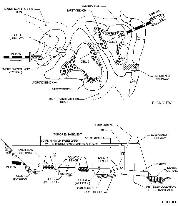
Figure 5.14.5. 4 Schematic of a Multi -Basin System
Northeast Tennessee Water Quality SCM Manual
Water quality basins typically include the following components.
One or more permanent pools of water
Live storage where stormwater volumes are temporarily stored before release in a controlled manner
An aquatic bench in the permanent pool, called a littoral zone, that serves as a biological filter for stormwater inflows from surrounding areas.
A sediment forebay for pretreatment of stormwater inflows from the contributing drainage area
An outlet (usually a multi-stage riser for ponds that provide flood control) and emergency spillway.
A safety bench.
A maintenance easement and maintenance access location(s).
A pond buffer and surrounding landscape, preferably composed of native vegetation
Design specifications for water quality basin components are provided in the following sections.
5.14.6 Design Requirements
The criteria provided in Table 5.14.6.1 shall be considered minimum standards and specifications for the design of water quality basins and their contributing drainage areas. Each criterion applies to all water quality basin types unless otherwise specified
Table 5.14.6.1 Design Specifications
Design Element Specification(s)
Water Quality Volume (WQv)
Use in a Water Quality Treatment Train
The water quality rainfall depth (P) for determination of WQv is P = 2.5 inches, or the WQv is the first 75% of the volume of the 1-yr, 24-hr storm, whichever is less. The design professional can select which volume to use.
Acceptable methods to determine WQv are presented in Chapter 3 (Standards, Methods, and SCM Selection).
If the water quality basin cannot manage the entire WQv for its contributing drainage area, it must be placed in a treatment train with another SCM. See treatment train policies and calculations in Chapter 3 (Standards, Methods, and SCM Selection) for treatment train policies and calculations.
Water quality basins should be located where site topography allows maximum stormwater storage with minimum excavation and construction.
An online configuration is designed and constructed so the main flow path for the drainage area passes through the water quality basin
Online and Offline
Water Quality Basin Configuration
If the online basin is designed to treat the WQv only, a bypass or overflow structure shall be provided to convey stormwater flows larger than the WQv safely around, or through, the basin without flooding or damaging it or adjacent areas. The bypass shall discharge to the onsite detention basin or stormwater conveyance system (properly sized in keeping with local government requirements)
If the online basin is designed to provide flood control as well as WQv treatment, an overflow structure (typically an emergency spillway) shall be provided to safely pass the peak discharge of the 100-year, 24-hour event with a minimum of 1-foot of freeboard, without negative impacts to downstream structures. The spillway shall be located a minimum of 0.1 foot above the water surface elevation (WSEL) in the basin for the 100-year, 24-hour storm.
An offline configuration is designed and constructed away from the main flow path for the drainage area. Offline basins are typically designed for WQv treatment only.
A diversion structure must be included to redirect the WQv from the main flow path to the basin while still allowing larger flows to remain in the main flow path. The structure shall include a low-flow orifice, weir, or other hydraulic structure, sized to pass the water quality
Northeast Tennessee Water Quality SCM Manual
Design Element
Specification(s)
peak discharge (Qwq) and direct it to the offline water quality basin. See Chapter 3 (Standards, Methods, and SCM Selection) for the calculation of Qwq.
Flow regulators (flow splitters, diversion structures, and overflow structures) shall be designed in keeping with Section 5.17 (Overflow Controls).
A maintenance easement shall be provided to the basin from a driveway, public or private road. It shall be designed as follows:
a minimum width of 20 feet shall
a maximum slope of no more than 15%
Maintenance Access and Easement
Minimum Drainage Area
a minimum drive path having a width of 12 feet free of permanently affixed obstructions (e.g., trees, pools, fences without gates, permanent signs, etc.) and appropriately stabilized to withstand maintenance equipment and vehicles.
to the extent feasible, allow vehicles to turn around.
The entire detention basin, including inlets, pretreatment devices, the storage area, embankments, outlet structure, and emergency spillway shall be included in the easement and shall be accessible from the easement’s drive path.
Access to the riser should be provided by lockable utility hole covers, and utility hole steps within easy reach of valves and other controls.
The minimum contributing drainage area to maintain a permanent pool is as follows:
Wet basins and wet ED basins: 25 acres.
Micropool ED basins: 10 acres
The local government may approve a smaller drainage area with an adequate water balance and anti-clogging device. See Chapter 3 (Standards, Methods, and SCM Selection) for water balance calculations.
Slope Water quality basins shall not be located on unstable slopes or slopes greater than 15%.
Water quality basins shall be designed to discharge the WQv and CPv fully within 24 to 48 hours after completion of a rain event using the orifice sizing guidance presented in Chapter 3 (Standards, Methods, and SCM Selection).
Orifice diameters for WQv and CPv shall be no less than 3 inches, regardless of drawdown time.
Drawdown Time
Minimum Hydraulic Head
Small orifices (less than 4 inches in diameter) should be protected against clogging with large debris. For example, install an over-perforated vertical standpipe with ½ inch orifices or slots that are protected by wirecloth and a stone filtering jacket over the orifice.
For basins intended to provide flood control, there are no restrictions on drawdown time for flood control storm events. Consult local government regulations regarding design storms and release rates.
Minimum hydraulic head = 6 to 8 feet (from inflow to outflow).
There are no restrictions on the minimum separation distance from the bottom of the basin to the seasonally high-water table except for certain situations, as follows:
Basins located above an underlying water supply aquifer: 2 feet
Minimum Depth to Water Table
Basins serving land uses that have the potential to discharge wastes or pollutants that cannot be managed by the water quality basin (as determined by the local government): 2 feet.
Basins located in a wellhead protection zone: 4 feet
Soil borings shall be used to determine the seasonally high-water table. See Appendix F (Policies for Soil Infiltration Tests & Soil Borings) for soil boring requirements.
Northeast
Design Element Specification(s)
The properties of the underlying soils are important to determine if the permanent pool can be maintained without a liner. The use of a soil survey can provide preliminary insight into the potential design, appropriate soil tests and subsurface analysis shall be performed to evaluate the suitability of in-situ soils.
In-situ Soil
Liners
Underlying soils of hydrologic soil groups (HSGs) C or D may be adequate to maintain a permanent pool.
Underlying soils of HSGs A or B will likely require a basin liner (see the row titled “Liners” in this table)
Clay or impermeable poly liners are required for basins located:
in close proximity to sinkholes.
where underlying soils will not sustain a permanent pool .
at land uses that have the potential to discharge wastes or pollutants that cannot be managed by the water quality basin (as determined by the local government).
where soil contamination is known or suspected.
Note: additional engineering beyond a clay liner may be required by the local government
Inflow channels shall be stabilized with flared riprap aprons or the equivalent energy dissipation to slow water to nonerosive velocities (maximum of 5 ft/sec).
A sediment forebay shall be provided immediately downstream of each inlet. Specifications are below. Additional requirements are provided in Section 5.16 (Inlets, Energy Dissipation and Pretreatment Measures).
Forebays shall be sized to hold a minimum of 10% of the WQv of the basin. Forebay volume can be considered as part of the total WQv, not additional volume of the basin.
Inlets, Energy Dissipation, & Forebay
Plan View Geometry
Ideal depths for forebays are 4 to 6 feet. When determining forebay geometry, greater depth is preferred over greater width. This allows the forebay to dissipate turbulent inflows without resuspending previously deposited sediment; however, safety concerns and ease of maintenance must be considered when designing sediment forebays.
Forebays shall contain a fixed vertical sediment depth marker to measure sediment deposition over time.
Although not required, consider hardening the bottom of the forebay with concrete or pavers to facilitate easier sediment removal.
Other pretreatment devices (e.g., MTDs, filter strips, etc.) cannot be substituted for sediment forebays; however, basins that are expected to readily encounter litter, leaves, and other floatables should include screens, grates, or other measures at the forebay discharge points to reduce the entry of floatable debris into the main basin.
Proper geometric design is essential to prevent hydraulic short-circuiting (unequal distribution of inflow), which results in the failure of the basin to achieve adequate levels of pollutant removal. Geometry specifications and guidance are as follows.
Minimum length-to-width ratio = 1.5:1
Ideal length-to-width ratio = 3:1 (to avoid short-circuiting).
Basins should be wedge-shaped when possible so that flow enters the basin and gradually spreads out, facilitating sediment deposition
The contours and shape (plan view) of the permanent pool should be irregular to provide a more natural landscaping effect. Baffles, basin shaping, or islands can be added within the permanent pool to increase the flow path. Figures 5.14.5.1 through 5.14.5.4 (above) provide examples of this irregularity.
Northeast
Design Element
Specification(s)
Permanent pool depth specifications are as follows:
Minimum depth = 3 feet
Maximum depth = 8 feet; a greater depth may be approved if measures are included to prevent pool stratification and anoxic conditions, and adequate safety measures are provided.
Permanent Pool Depth and Volume
Storage Capacity
Designing the basin with deep depths near the outlet will result in cooler bottom water discharges from the pond. To some degree, this can mitigate downstream thermal effects caused by discharges of warm stormwater, especially for ponds that discharge directly to a stream or other natural waterbody. However, ensure adequate access and safety measures are included on (or with) the outlet riser located in the deep area.
Permanent pool volumes are determined based on basin type, as follows.
Wet basins: 100% of the WQv
Wet ED basins: 50% of the WQv.
Micropool ED basins: 0.1 inches per impervious acre draining to the pond
Note: the storage volume of the forebay (minimum of 10% of the WQv) can be considered part of the total design requirement and may be subtracted from the WQv for permanent pool sizing.
See “Energy Dissipation & Pretreatment” in this table for more information.
Designs for basins that can impound more than 30 acre-feet of water shall adhere to the Tennessee Safe Dams Act.
Routing calculations must demonstrate that the storage volume of the basin is adequate (not including freeboard) for all design storms. See Chapter 3 (Standards, Methods, and SCM Selection) for more information on storage design requirements.
See Figure 5.14.6.1 illustrates the specifications in this table row.
SLOPES
Maximum side slopes = 3:1 (horizontal to vertical).
Steeper slopes (2:1 or higher) may be allowed if one side of the basin, extending from the maintenance right of way to the forebay and outlet structure, has a maximum slope of 3:1 to facilitate access for maintenance and repair.
Slopes greater than 3:1 and having a height of 10 feet or more must be benched.
Riprap-protected embankments shall be no steeper than 2:1.
Profile View
Geometry
PERIMETER BENCHING
The perimeter of the basin is surrounded by two benches: safety and aquatic. Information and specifications are as follows.
Safety bench: The safety bench is a gently sloped, graded area that extends outward from the permanent pool. The purpose of the bench is to reduce the safety risks of pedestrians falling into deep water by providing a flat or gently sloped area adjacent to the permanent pool. The safety bench also provides valuable habitat area for pond flora and fauna
Maximum bench slope = 6%; although gentler slopes are preferred.
For large ponds, the safety bench shall extend no less than 15 feet outward from the normal water edge to the toe of the basin side slope.
The requirement for a safety bench may be waived if basin side slopes are 4:1 or gentler.
When selected and maintained appropriately, safety bench vegetation can dissuade use of the basin by waterfowl. See Section 5.14.8 (below) for more information.
Design Element
Specification(s)
Figure 5.14.6.1 Typical Water Quality Pond Geometry in Profile View
Profile View
Geometry (continued)
Outlet Structures
UPLAND EMBANKMENTS (OUTWARD FROM THE SAFETY BENCH)
Maximum side slopes = 3:1 (horizontal to vertical)
Maximum height = 20 feet
Minimum freeboard = 1 foot; measured from the top of the water surface for the highest detained storm to the lowest point of the dam embankment, not counting the emergency spillway.
All embankments and spillways shall be designed to TDEC rules and regulations as applied to the Safe Dams Act of 1973, where applicable.
UPLAND AREAS
Areas external to the embankments (surrounding the basin) that are above the high-water elevation shall be sloped toward the basin to prevent standing water. Careful finish grading is necessary to avoid the creation of upland surface depressions that may retain runoff.
See Chapter 3, Section 3 5 (Storage Facility Outlet Structures) for more information on multi-stage riser design. Additional requirements and information are as follows.
Note: the preferred minimum orifice size is 3 inches. If a smaller orifice is required, provide internal orifice protection with an over-perforated vertical standpipe with ½ inch orifices or slots that are protected by wirecloth and a stone filtering jacket. Adjustable slide gates can also be used to achieve this equivalent diameter.
WATER QUALITY BASINS DESIGNED FOR WQV CONTROL ONLY
When a water quality basin is used for control of the entire WQv only, it provides control of both the WQv and CPv. In this case, the outlet structure can be simple, as follows.
Wet basins: The WQv is fully contained in the permanent pool. Thus, an orifice is not necessary. As a new WQv enters the basin, it simply displaces the WQv from the previous storm. Thus, an off-line basin providing only water quality treatment (i.e., not flood control) can use a simple overflow weir as the outlet structure.
Wet ED and micropool ED basins: The WQv is only partly contained in the permanent pool, thus there is a need for an outlet that is sized to pass the extended detention portion of the WQv that is surcharged on top of the permanent pool in 24 hours. Again, for an off-line basin, a properly sized overflow weir can serve as an outlet structure.
Design Element Specification(s)
WATER QUALITY BASINS DESIGNED FOR WQV AND FLOOD CONTROL
When a water quality basin is used for flood control, the basin provides WQv and CPv control (together), as well as detention and peak flow control of larger storm events. In this case, discharge from the basin is typically accomplished with the use of a concrete or corrugated metal multi-stage riser and outlet barrel. Figure 5.14.6.2 illustrates such a structure.
Figure 5.14.6.2 General Schematic of a Multi -Stage Riser for a Water Quality Basin
1.0 FT. MINIMUM
0.1 FT. MINIMUM
Outlet Structures (continued)
Qp 2 YR.
PERM. POOL UP TO Qp 25 YR. Qp 100 YR.

REVERSE-SLOPE PIPE w/ VALVE
POND DRAIN w/ VALVE
HOOD/TRASH RACK/ SKIMMER
MULTI-STAGE RISER
BARREL EMERGENCY SPILLWAY
ANTI-SEEP COLLAR
Wet basins: The WQv is fully contained in the permanent pool. As a new WQv enters the basin, it must displace the WQv from the previous storm. The preferred design is a reverse slope pipe attached to the riser. Its inlet is submerged 1 foot below the elevation of the permanent pool to prevent floatables from clogging the pipe and to avoid discharging warmer water at the surface of the pond. Its outlet is located 0.1 ft above the permanent pool elevation.
Wet ED and micropool ED basins: The WQv is only partly contained in the permanent pool, thus the extended detention portion of the WQv must be discharged. The preferred design is a reverse slope pipe attached to the riser, with its inlet submerged 1 foot below the elevation of the permanent pool to prevent floatables from clogging the pipe and to avoid discharging warmer water at the surface of the pond.
Flow will first pass through this orifice, which is sized to release the ED volume in 24 hours. The next outlet is sized for the release of the first (i.e., most frequent) flood control design storm. The outlet (often an orifice) invert is located at the maximum elevation associated with the extended detention portion of the WQv and is sized to release the first flood control design storm in a 24-hour period
If necessary, the water quality outlet shall be fitted with adjustable slide gates or another mechanism that can be used to adjust detention time.
All basin types: Higher flows (e.g., the 2-yr and higher storms) pass through openings or slots protected by trash racks further up on the riser. The largest design storm often discharges through a weir at the top of the riser or via weir flow through the open top of the riser.
Northeast Tennessee Water Quality SCM
Design Element Specification(s)
REQUIREMENTS FOR OUTLET STRUCTURES (ALL BASIN TYPES)
Alternative hydraulic control methods for an orifice include the use of a broad-crested, rectangular, V-notch, or proportional weir, or an outlet pipe protected by a hood that extends at least 12 inches below the normal pool. See Chapter 3, Section 3.5 (Storage Facility Outlet Structures) for more information.
After entering the riser, flow is conveyed through the barrel and is discharged downstream. Anti-seep collars shall be installed on the outlet barrel to reduce the potential for pipe or embankment failure.
All outlet structures and orifices shall be designed so as not to permit access to, or entry by, children. Orifices, weirs, and other openings shall be protected with permanently affixed or locked grates, trash racks, or other similar features.
Outlet Structures (continued)
Outlet risers shall be located within the basin embankment for maintenance access and safety.
Each basin shall have a bottom drainpipe with an adjustable slide gate that can completely or partially drain the basin within 24 hours.
Water shall not be discharged from the basin in an erosive manner. Riprap, plunge pads or pools, or other energy dissipators shall be placed at the outlet of the barrel to prevent scouring and erosion. If a basin outlet discharges immediately to a stream, additional care is needed to minimize disturbance in the stream and floodplain
For basins that discharge directly to a mapped floodplain, the downstream invert elevation of the outlet barrel shall be at least 1 foot above the base flood elevation.
For basins that discharge directly to an unmapped stream or waterbody (e.g., stream or lake), the downstream invert elevation of the outlet barrel shall be at least 1 foot above the elevation of the edge of the bank (for a stream) or normal pool elevation (for a lake).
Emergency Spillway
Additional Safety Features
An emergency spillway shall be included in the water quality basin design, sized to safely pass the 100-year, 24-hour storm event The spillway prevents basin water levels from overtopping the embankment and causing structural damage to the embankment. The emergency spillway shall be located so that downstream structures will not be impacted by spillway discharges.
A minimum of 1 foot of freeboard shall be provided, measured from the top of the water surface elevation for the extreme flood to the lowest point of the dam embankment, not counting the emergency spillway.
A pond buffer should be provided that extends 25 feet outward from the maximum water surface elevation of the pond. The pond buffer should be contiguous with other buffer areas that are required by existing regulations (e.g., stream buffers) or that are part of the overall stormwater management concept plan. No structures should be located within the buffer, and an additional setback to permanent structures may be provided.
Existing trees should be preserved in the buffer area during construction. To discourage resident waterfowl populations, the buffer can be planted with trees, shrubs, and native ground covers. The soils of a pond buffer are often severely compacted during construction to ensure stability. The density of these compacted soils is so great that it effectively prevents root penetration and, therefore, may lead to premature mortality or loss of vigor. Consequently, it is advisable to excavate large, deep holes around the proposed planting sites and backfill these with uncompacted topsoil.
See requirements for safety benches and outlet/orifice access and entry prevention above. All embankments and spillways shall be designed to meet TDEC rules and regulations as applied to the Safe Dams Act of 1973, where applicable. Trees are not allowed on embankments.
Pond Buffer
Northeast Tennessee Water Quality SCM Manual
Design Element Specification(s)
The property owner may consider fencing the basin for the purpose of safety management. Posting warning signs near the basin to prohibit swimming and fishing in the facility is encouraged.
Controls for Waste & Other Pollutants
Appropriate controls shall be included in the design of the contributing drainage area to the SCM to address any wastes and other Pollutants (see Table 5.14.3.1 above) that are expected on the property after construction. Use the proposed land use as a guide to determine appropriate controls. Examples of such controls include, but are not limited to, dumpsters, trash cans, covered materials/waste storage areas, covered materials transfer areas, oil and grease waste controls, and pet waste stations.
5.14.7 Design Procedure
Table 5.14.7.1 provides the design procedure for a water quality basin
Table 5.14.7.1 Design Procedure
Step Design Activity
Evaluate water quality basin feasibility.
Step 1
Step 2
Use the feasibility criteria provided in Tables 5.14.3.1 and 5.14.4.1 to determine if a water quality basin is feasible for the selected location on the land development site. Consider especially whether it is appropriate for the proposed development based on the intended land use of the property, the maintenance burden, and assumptions or knowledge of how the property owner(s) will care for the water quality basin after construction (e.g., self-maintenance, property/facilities management maintenance, landscape contractor). If possible, include the property owner(s) in SCM selection since they will be responsible for maintenance. If a water quality basin is determined to be feasible and appropriate for the proposed development, create a rough layout of its dimensions, taking into consideration existing trees, utility lines, and other obstructions to ascertain if it will fit into the desired space, given its general design requirements.
Determine the goals and primary function of the water quality basin.
Consider whether the intention is to:
Comply with the local government stormwater quality requirements (i.e., treat the WQv, provide flood control, address an onsite or regional drainage issue, etc.).
Enhance landscape and provide aesthetic qualities.
Determine basin location and preliminary geometry.
Step 3
Step 4
This step creates a rough grading design for the basin (contours, including the sediment forebay, safety bench, aquatic bench, and deep pool), and determines the probable locations of inlets, the outlet structure, its discharge, and the emergency spillway. Evaluate the side slopes, depth, and available storage volumes.
Create the basin design for WQv/CPv, flood control, and pretreatment.
Use the hydrologic methods established in Chapter 3 (Standards, Methods, and SCM Selection) to determine the WQv for the basin’s contributing drainage area. If the entire WQv can be managed by the basin, no additional design is required for CPv control.
Consult local government requirements for detention/flood control standards (e.g., post-development peak discharge shall not exceed pre-development peak discharge), required design storms, data requirements, and hydrologic methods for peak discharge, stage, and storage determination.
Note: the preferred minimum orifice size is 3 inches. If a smaller orifice is required, provide internal orifice protection with an over-perforated vertical standpipe with ½ inch orifices or slots that are protected by wirecloth and a stone filtering jacket. Adjustable slide gates can also be used to achieve this equivalent diameter.
Set up the stage-storage-discharge relationship for the basin and control structure, using it as follows.
Northeast Tennessee Water Quality SCM
Step Design Activity
Determine the WQv volume, the release rate, and the volume and WSEL of the permanent pool
Wet basin: Size permanent pool volume to 1.0 WQv.
Wet ED basin: Size permanent pool volume to 0.5 WQv. Size extended detention volume to 0.5 WQv.
Micropool ED basin: Size permanent pool volume at 0.1 foot per impervious acre Size extended detention volume to the remainder of WQv.
Determine the peak discharges (Qp), and associated volumes and WSEL for all flood control (detention) design storms.
Size the pretreatment sediment forebay for a minimum of 10% of the WQv of the basin, taking care not to reduce the size of the permanent pool
A sediment forebay is required at each inlet of the basin. For ponds that have multiple inlets, determine the volume/sizing of each forebay based on expected inflow volumes at each inlet, ensuring that, together, the forebays will comply with the 10% requirement.
Since the volume of the forebay can be considered a portion of the total design volume, refine the basin volumes, WSELs, and orifice elevations and sizes for WQv and flood control, accordingly, completing the design of orifices on the outlet structure.
Size the emergency spillway based on local government requirements for design storm, freeboard, and embankment slopes and elevations. Typically, the invert elevation of the emergency spillway is 0.1 foot above the largest design storm’s water surface elevation.
Investigate potential basin hazard classification.
Step 5
Step 6
Step 7
Step 8
Step 9
The design and construction of stormwater management basins are required to follow the latest version of the TDEC Rules and Regulations Application to the Safe Dams Act of 1973.
Complete the outlet structure design.
Include trash racks, grates, covers, and other measures for basin safety and to prevent clogging of the outlet barrel.
Design the inlets (all basin types) and any flow regulators or overflow structures (for OFFLINE basins only).
Use Sections 5.16 (Inlets, Energy Dissipation, and Pretreatment Measures) and 5.17 (Overflow Controls) for requirements.
Design inlets, maintenance access and easement, and remaining safety features.
See Table 5.14.7.1 for more details.
Design vegetation and protection measures.
The vegetation design shall be in accordance with the vegetation design requirements provided in Table 5.14.8.1. Use guidance found in Section 5.14.8 (below) to design protection measures.
5.14.8 Vegetation Design Requirements
Aquatic vegetation can play a significant role in pollutant removal in a water quality basin, including enhancing the appearance of the basin, stabilizing side slopes, serving as wildlife habitat, and temporarily concealing unsightly trash and debris. Plants are the primary visual attribute of the water quality basin and should enhance the landscaping of the property
Like any SCM component, basin vegetation has design, installation, and maintenance specifications. Much of the design and maintenance of a water quality basin center on plant coverage and replacement. Table 5.14.8.1 provides the vegetation specifications for water quality basins.
Table 5.14.8.1 Vegetation Design Specifications
Vegetation Design Element
Minimum Coverage
Waterfowl Control
Plant Survival
Plant Selection
Specification(s)
Permanent pool: Wetland plants shall cover 100% of the aquatic bench around the perimeter of the basin and in shallower areas of the permanent pool (areas less than 4 to 5 feet), without overcrowding. Native wetland plants are preferred See also the ‘Waterfowl Control’ row of this table.
A minimum of 90% of the area above the permanent pool area, including the safety bench must be covered by vegetation. Areas of bare soil above the permanent pool are not allowed, therefore any areas not covered by vegetation must be permanently stabilized with other forms of ground cover (sidewalks, etc.). Mulch, pea gravel, and similar forms of ground cover are prohibited within the embankments to avoid clogging of outlet structures
The minimum coverage requirement must be achieved within the first two growing seasons (March through November) after installation, and then maintained thereafter.
Water quality basins can attract waterfowl. The presence of herons, egrets, and other desirable waterfowl can improve the basin as an interesting amenity. However, a lack of waterfowl management measures can cause problems. Geese and ducks can be particularly destructive because they tend to defoliate the area surrounding the permanent pool and can create fecal bacteria issues. A key factor in managing waterfowl is to discourage foraging and residence along the shoreline. Guidance is below.
Select and plant tall grass (preferably native) for the safety bench and include signs to identify this area as a “no mow” zone (see Figure 5.14.9.1). This lush, watery landscape attracts waterfowl to the water, but does not encourage them to exit the water and take up residence. Signs discouraging waterfowl feeding may also be warranted in areas where sidewalks or trails are in close proximity to a basin.
While impractical for some pond owners, physical barriers that may deter the birds include netting, wire or string grids around the pond, and fencing.
Vegetation installation or replacement is required when the minimum coverage goals are not achieved.
Aquatic bench and shallow areas of the permanent pool: Wetlands plants are encouraged and will have more survival ability. The best elevations for establishing wetland plants, either through transplantation or volunteer colonization, are within 6 inches (plus or minus) of the normal pool elevation. More information on wetland plants can be found at the following websites:
http://wetlands.fws.gov/
https://plants.usda.gov/home/wetlandSearch
Safety bench: No restrictions; however tall grass is recommended from the edge of the permanent pool for at least several feet toward the embankments
Upland areas within the embankments: No restrictions
General recommendations:
Between the permanent pool and on the embankments, select plants resistant to cycles of drought and inundation, as both conditions will occur. For guidance, consult a plant and landscape expert, such as a landscape architect, local nursery, or Master Gardener from the Tennessee Extension Master Gardener program.
(https://mastergardener.tennessee.edu/).
Native plant species better suited to local hydrologic conditions are recommended.
Plants suitable for United States Department of Agriculture Plant Hardiness Zoned 6b and 7a (depending on your zip code) are recommended.
Northeast Tennessee Water Quality SCM Manual
Vegetation Design Element
Plant Location
Specification(s)
Deciduous trees and shrubs are strongly discouraged as leaf drops can contribute to basin clogging.
Consider future maintenance needs of vegetation when designing the basin. The level of plant care needed to maintain the landscape and their potential impacts on the maintenance of basin components should influence their selection to minimize care needs as much as possible. For example, potential long-term maintenance issues associated with shrubs and trees include poor grass growth, outlet clogging due to leaf/debris drop, and root damage to embankments and components. Future property owners will need to deal with all of these issues.
Requirements pertaining to the location of plants are as follows:
Woody vegetation such as trees and shrubs shall not be planted on, and within 15 feet of the toe of, the dam and embankments, and must be at least 25 feet from the outlet and spillway structures.
Mulch, wood chips, pea gravel, and other loose (unanchored) soil stabilization materials are prohibited around inlets and within the embankments
Compliance with the vegetation standards set forth in Table 5.14.6.1 shall be shown in a vegetation plan that is included with the water quality management plan (WQMP). Plan preparation requirements are below.
The plan must be prepared by a professional qualified in landscape design by their education or experience.
The plan shall include one or more labeled plans/details (to scale) showing the plants to be installed, their numbers, and locations. Plan notes showing a plant schedule and installation instructions are encouraged. This additional information allows both the plant installer at the time of construction, as well as the person(s) responsible for maintenance of the SCM after construction, to understand the original vegetation design and its compliance with the minimum standards.
Landscaped SCMs may not be recognized under the local government’s codes as property landscaping. Therefore, additional requirements for property landscaping may apply.
5.14.9 Protection Design Guidance
SCMs designed for stormwater quality purposes must be maintained in keeping with the approved SCM design for the life of the land development Design professionals can assist property owners with this requirement by including protective features in and around SCMs to limit the potential for damage by external factors. Often, the landscape and impervious features around an SCM can be tailored to its specific needs, and therefore used to protect its critical components.
For water quality basins, protection is about more than preventing damage to the SCM and safety since they are a drowning risk. Protective measures are especially important on all slopes, the safety bench, and around the outlet structure They are well-suited to a variety of protection methods (see Table 5.14.9.1). See also Figure 5.14.9.1
Table 5.14.9.1 Water Quality Basin Protection Measures*
Natural fencing such as vegetation borders/screens (woody/prickly shrubs or tall grass)
Dense vegetation or clumping at the perimeter
Physical fences
Educational or directive signs (see Figure 5.14.9.1)
Pet waste stations and trash cans near the SCM
* The list presented in the table is not exhaustive. There may be other possible protection measures.
*Water quality basin protection measures must be maintained to design specifications. See section 5.14.10 on maintenance requirements
Northeast Tennessee Water Quality
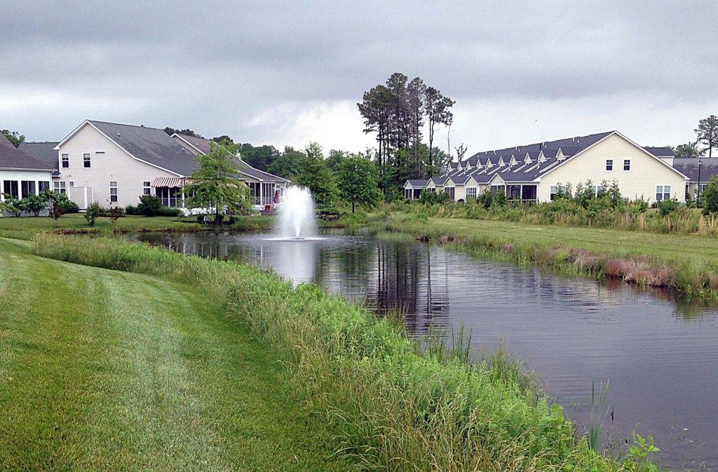
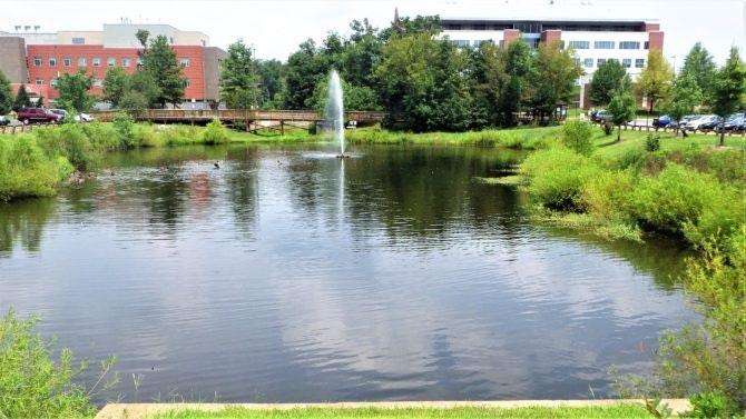
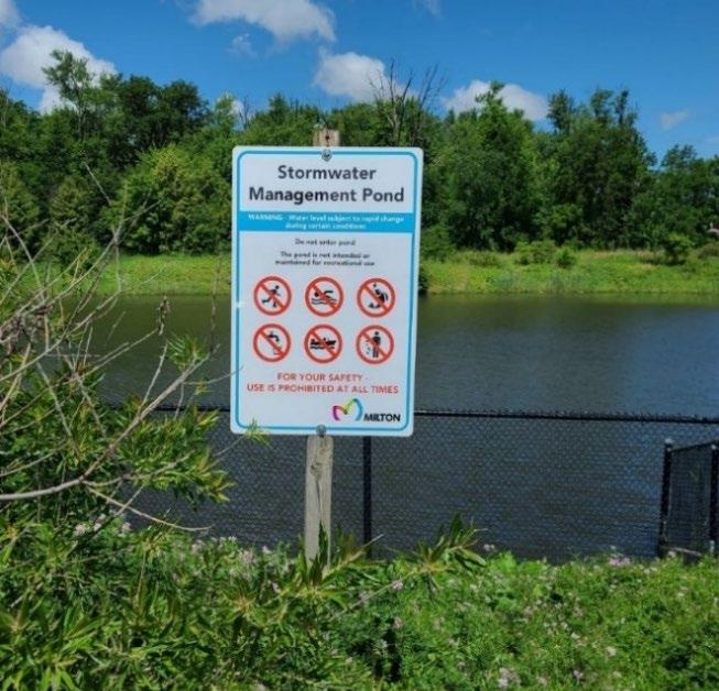

5.14.10 SCM Maintenance on an Active Construction Site
Dense vegetation for a few feet within the

people and waterfowl
Top
Educational signage and fencing are protection measures for a water quality basin in Milton, Ontario, Canada. (Source: Town of Milton); Bottom left: Dense vegetation, a pedestrian bridge, and attractive landscaping make this wet basin an amenity (Source: George Mason University); Bottom middle: No mow sign used in Carrboro NC (Source: City of Carrboro NC); basin safety signs can be purchased commercially. (amazon.com).

SCM maintenance is regulated by local government ordinance from the moment they are installed. SCMs must also pass a final inspection prior to construction termination. This inspection will be performed to ensure they are constructed in accordance with the approved WQMP, undamaged, and free of sediment and debris. This section applies to water quality basins once it is constructed in its permanent (post-construction) state. Thus, SCM maintenance is good practice to ensure construction termination goes smoothly. Relevant policies are as follows:
The property owner is responsible for SCM maintenance. If the property is still an active construction site, these responsibilities may fall to the land disturbance permittee until the project receives final approval from the local government and/or a Certificate of Occupancy.
Property owners may have others, such as a site contractor or landscaping company, maintain the water quality basin on their behalf. However, the local government will hold the property owner responsible for ensuring it is maintained in proper operating condition (i.e., as designed and constructed) regardless of who performs maintenance activities.
Maintenance activities, which include ensuring proper operation of the SCM as designed and required SCM inspections, must begin immediately following installation of the water quality basin
Top left:
safety bench can deter
( Source: Solitude Lake Management).
right:
Northeast Tennessee Water Quality SCM
Maintenance activities shall be performed in keeping with the Northeast Tennessee SCM Inspection and Maintenance Manual Additional guidance on maintenance of newly installed water quality basins located on active construction sites is provided in Table 5.14.10.1.
Table 5.14.10.1 Maintenance Activities for Newly Installed Water Quality Basins
Area or Component
Contributing Drainage Area
Keep the contributing drainage area clean. Trash, debris, and sediment from construction activities discharged to a fully constructed basin can clog pretreatment measures, kill basin plants, reduce the basin’s design capacity, block the inlets, and clog outlet structures.
Stabilize the area as soon as possible to prevent the discharge of sediment to the SCM.
Cover stockpiles of construction and landscape materials to prevent their exposure to rainfall.
Vegetation management should focus on ensuring the vegetation planted in and around the basin is well-established and healthy, to meet the vegetation design standard for the SCM. The following activities may apply:
Watering. Depending on rainfall, regular watering may be necessary to keep vegetation healthy and thriving. Evaluate watering needs based on vegetation type, season, and near-term precipitation conditions.
Fertilization. Fertilization should be performed only when needed, based on the needs identified by a soil test and of the vegetation planted in the SCM. In general, fertilization of SCMs is discouraged because it introduces pollutants (nutrients) into the SCM.
Weed and invasive species control. Remove undesirable plants manually instead of using herbicides. Herbicides can enter the water during a rainfall, kill aquatic plants, and be discharged into local streams.
Water Quality Basin Area
Spot Reseeding. Bare or eroding areas on the basin’s embankments shall be stabilized with permanent vegetation as soon as they are noticed.
Plant Replacement. Dead plants must be removed and replaced. Unhealthy plants should be removed and replaced if they cannot be rehabilitated.
Inspect the installed SCM at least weekly and after every storm event until construction is terminated. Look for signs of erosion, significant sediment accumulation, stormwater short-circuiting, outlet clogging, vegetation distress or removal, the presence of burrowing animals, and long-standing high water. Check weirs, check dams, and inlet and outlet structures to ensure proper functioning.
Clean the inlets, sediment forebay, and outlet structure when needed.
Check for signs of unhealthy or overpopulation of plants and/or fish (if utilized).
Note signs of algal growth or pollution, such as oil sheens, discolored water, or unpleasant odors. Determine the cause and correct the issue.
Check for proper operation of control gates, valves, or other mechanical devices.
Note changes to the basin or contributing drainage area as such changes may affect the basin’s performance.
Alert onsite subcontractors to the SCM and the following requirements:
No stockpiling of material in the basin and no exposed stockpiles in the basin’s drainage area.
Education
Remove sediment, trash, debris, and empty trash cans frequently.
Advise landscaping subcontractors on proper protection and maintenance of basin plants.
No dumping of lawn clippings or landscape debris.
Northeast
5.14.11 References
ARC. Georgia Stormwater Management Manual Volume 2 Technical Handbook, 2016 Edition. Atlanta Regional Commission, 2016
Center for Watershed Protection. Manual Builder. Stormwater Manager’s Resource Center, Accessed July 2005. Metropolitan Nashville and Davidson County, Stormwater Management Manual Volume 4 Best Management Practices. 2006.
SOLitude Lake Management www.solitudelakemanagement.com 2024
5.15 Underdrain and Internal Water Storage
5.15.1 Introduction
design specification
This section provides design specifications for underdrains and Internal Water Storage (IWS) components of SCMs that are not MTDs Underdrain designs for MTDs are based on the manufacturer’s design and therefore may differ from the specifications herein. Regardless, underdrains for Tier 2 MTDs must be designed to provide at least 12-inches of IWS.
Table 5.15.1.1 lists the SCMs that include design configurations with underdrains and/or IWS. It also shows which SCMs can be designed without these features (i.e., Group 1 SCMs), should onsite conditions be optimal for full infiltration of the WQv. It should be noted that, although unlikely, Group 1 SCMs may be subject to a Class V Injection Well Permit pursuant to Tennessee Department of Environment and Conservation (TDEC) rule 0400-45-06-.06. A Group 2 SCM is not subject to the permit since it is designed with an underdrain.
Table 5.15.1.1 Underdrain and Internal Water Storage Applicability by SCM
by design specification section # and SCM name)
1 – Group 1 SCMs are allowed only with optimal onsite conditions. See the Infiltration Feasibility Form in Appendix C for more information. 2 – Manufactured Treatment Devices (MTDs) may differ than those listed in this table. Regardless, Tier 2 MTDs must include at least 12-inches of IWS.
The design configurations shown in Table 5.15.1.1 are presented in the figures that follow. Although a specific SCM is shown in each figure, the design configuration can be applied to other SCMs in the table, in keeping with the table’s applicability information.
Figure 5.15.1.1 demonstrates a “no underdrain” design configuration in a bioretention area. This configuration can be applied in the first five SCMs listed in Table 5.15.1.1 under the Group 1 column ONLY if all the conditions included in the Infiltration Feasibility Form (see Appendix C) are satisfactory for full infiltration of the water quality volume (WQv).
5.15.1.1 No Underdrain Design Configuration (Infiltration Only)
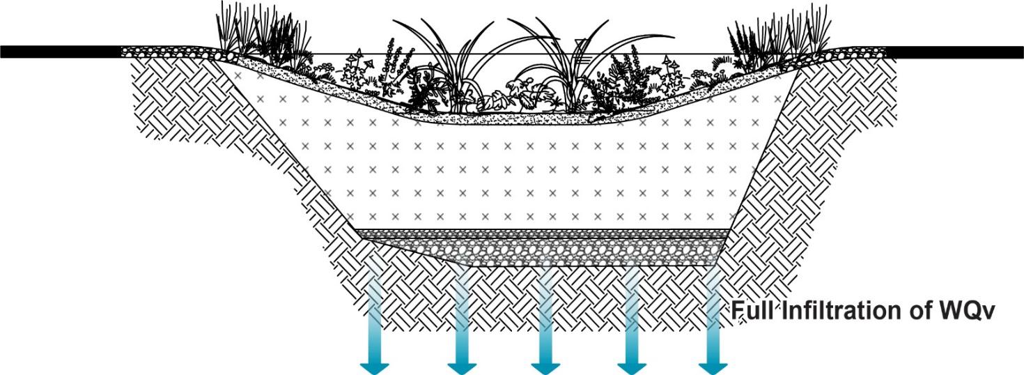
Figures 5.15.1.2 and 5.15.1.3 demonstrate the only underdrain configurations allowed for Group 2 SCMs, again using a bioretention area in the figure. A minimum of 12 inches of IWS is required for all biofiltration (i.e., Group 2) SCMs 1 . However, IWS can be included in all SCMs in Table 5.15.1.1 to provide a greater level of water quality treatment or address a small, localized drainage or flooding issue For both applications, the SCM is designed to treat a volume of water that is more than the required WQv.
To create IWS, underdrains must either have an upturned elbow (Figure 5.15.1.2) or be elevated above an IWS layer (Figure 5.15.1.3). Both configurations creating an anoxic zone by increasing the hydraulic residence time of water in the SCM within the IWS. This facilitates improved pollutant removal and denitrification. Some infiltration can occur; however, it is often limited by the low permeability in-situ soil Both configurations can be used in karst locations, although an impermeable liner at the bottom is recommended to prevent sinkhole formation caused by near constant wet conditions in the IWS.

Figure
Figure 5.15.1.2 Upturned Elbow Underdrain Design Configuration
Figure 5.15.1.3 Elevated Underdrain above IWS
Internal Water Storage Area

Some infiltration of WQv can occur if an impermeable liner is not included in the design

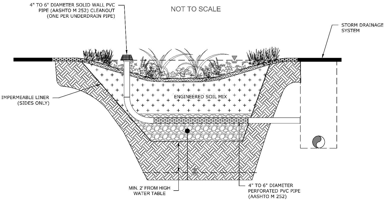

Figure 5.15.1.4 demonstrates the typical underdrain configuration for both a permeable pavement system (porous asphalt in this case) and sand filter, which are the Group 3 SCMs that include underdrains It is important to note that a permeable pavement system can include underdrain design configurations with IWS, as shown in Figures 5.15.1.2 and 5.15.1.3 to increase IWS for purposes of denitrification or increased water storage to address drainage issues. However, these underdrain design configurations do not allow a permeable pavement system to be considered a Group 2 SCM due to the lack of biofiltration (water filtration through plants and soil media)
Figure 5.15.1.4 Underdrain at Bottom (No Infiltration)
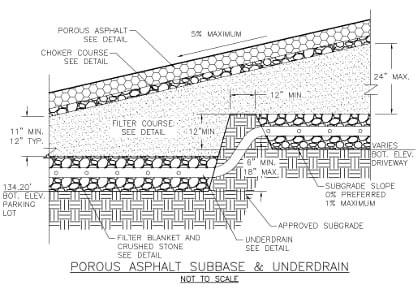
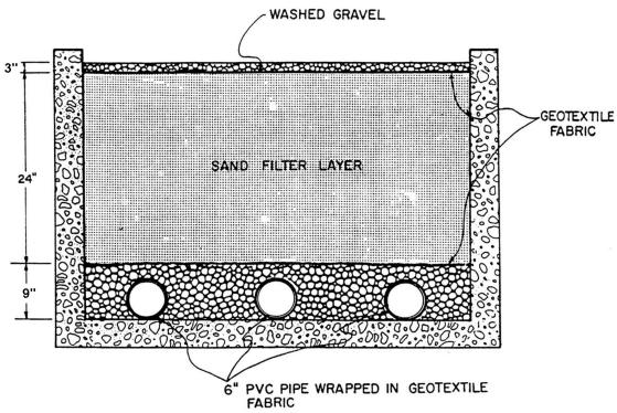
Left: Example of underdrain design in a tiered permeable pavement system for a parking lot driveway in Dedham, Massachusetts (Source: Ecological Landscape Alliance); Right: Cross-section of a sand filter showing the underdrain lines on the bottom of the SCM (Source: Department of Energy and Environment Stormwater Management Guidebook, Washington DC)
Graphic adapted from the Minnesota Stormwater Manual
Northeast
5.15.2 Underdrain Design Specifications
Table 5.15.2.1 provides design specifications and guidance for underdrains.
Table 5.15.2.1 Underdrain Design Specifications
Design Element
Pipe Material
Pipe Layout & Spacing
Slope
Stone Jacket
Stone Choker Layer
Geotextiles
(Filter Fabric and Pipe Socks)
Cleanouts
Specifications
For lateral and longitudinal lines, and vertical inflows (to distribute or increase inflows to subsurface layers):
4 to 6 inch polyvinyl chloride (PVC) pipe (Schedule 40) or corrugated high density polyethylene (HDPE) pipe (AASHTO M252) with ⅜ inch perforations, spaced at a minimum of six (6) inch centers, and a minimum of 4 holes per row
Underdrain line layouts can vary as some SCMs, especially bioretention areas, can have a free form design. More than one line may be needed. Use the specifications below to design a configuration that best serves the SCM. Figure 5.15.2.1 provides examples of pipe spacing.
Minimum surface area = 1 underdrain for every 1,000 ft2 of SCM surface area
Maximum distance between lines = 10 feet on center
Minimum slope = 0.5%
The underdrain slope shall not cause water flow to exceed 5 ft/sec
The design slope of the underdrain should be maintained through the entire length of the pipe. Where this is not possible within a single length of pipe, a tiered underdrain design can be used.
An example of a tiered design is shown in Figure 5.15.1.4
Lateral and longitudinal underdrain lines shall be placed in a stone jacket consisting of 8 inch clean, double-washed AASHTO #57 stone
A stone choker layer separates the underdrain from soil or sand layers located above the pipe jacket. Specifications are as follows.
Material = AASHTO #8 stone or AASHTO #89 pea gravel, double-washed and clean
Thickness = 3 to 4 inches
Pipes embedded in stone:
Avoid the use of geotextiles in underdrain system designs (as a pipe sock in place of the stone jacket or between SCM subsurface layers) as they have the propensity to become clogged, thus causing an expensive repair.
Pipes embedded in sand:
While a sand bedded underdrain is not included in the design specifications in this manual, should there be a need to bed a perforated pipe in the sand, pipe socks should be used. This circular knit geotextile filter fabric is a water-permeable barrier that will keep sand deposits from building up in the pipe, extending its useful life (see Figure 5.15.2.1).
Note:
The above statements do not preclude the placement of a permeable geotextile on the sides (and sometimes, the bottom) of an SCM excavation when specified for the SCM in its design specification This is done to prevent the migration of in-situ soils surrounding the excavation into the SCM layers.
An underdrain cleanout is a vertical pipe connected to, and extending from, an underdrain line to the surface of the SCM. A cleanout allows access to the underdrain for maintenance Often, unclogging an underdrain can be done via a cleanout rather than excavating the entire SCM Cleanouts shall be designed as follows:
One (1) cleanout per underdrain pipe shall be provided. For example, if an underdrain collection system includes 3 parallel underdrain pipes, each pipe will have a cleanout.
Northeast Tennessee Water Quality SCM Manual
Design Element
Observation Wells
Valves (optional)
Underdrain Outlet
Specifications
Cleanouts shall be constructed of a 4 to 6 inch diameter solid wall (not perforated) PVC pipe (AASHTO M252) that couples with the perforated underdrain pipe.
Cleanouts shall extend to the surface of the SCM, rising high enough to be readily visible to SCM maintainers and landscape crews. If the SCM will have a grassed surface, ensure cleanouts are tall enough to avoid being run over by mowers.
Cleanouts shall have a watertight, removable cap and lock to prevent tampering and vandalism.
An observation well is a pipe that is used to determine if there is standing water in an SCM’s subsurface layers. Design specifications are as follows:
Two (2) observation wells shall be installed in every SCM listed in Table 5.15.1.1 (above). One shall be located at the upstream end and one at the downstream end, with each placed on the centerline of the SCM.
Observation wells shall be constructed as follows:
4 inch diameter perforated PVC pipe (AASHTO M252) is used within gravel layer(s) to allow inflow into the pipe and extends to the bottom of the SCM.
4 inch diameter solid wall PVC pipe (AASHTO M252) is attached with a watertight connection to the perforated pipe, and extends above gravel layers (i.e., in soil, sand, and mulch layers and above grade) to the surface of the SCM
The observation well shall rise high enough above the SCM to be readily visible to SCM maintainers and landscape crews. If the SCM has a grassed surface, ensure cleanouts are tall enough to avoid being run over by mowers.
A visible (e.g., brightly colored) floating marker shall be placed in each observation well to allow the viewer to see the water level.
The top of each well shall have a watertight, removal cap and lock to prevent tampering and vandalism.
An underdrain cleanout may be used as an observation well; however, the cleanout/observation well shall be designed and installed in keeping with the cleanout design specifications provided above.
For each underdrain, install an accessible knife gate valve on its outlet to allow the option of operating the system as either a infiltration system, filtration system, or both. The valve should provide the ability to adjust the discharge flow so the sum of the infiltration rate plus the underdrain discharge rate equals a 48-hour drawdown time.
When an underdrain is used, discharges shall not exit the underdrain outlets in an erosive manner (> 5 ft/sec). Due to the slow rate of discharge, outlet erosion protection is generally unnecessary. For SCMs with underdrains that are used for flood control, the outlet barrel material shall be reinforced concrete.
For underdrains that daylight on grade, include a marking stake and animal guard
5.15.2.1 Examples of Underdrains with Lateral and Longitudinal Lines
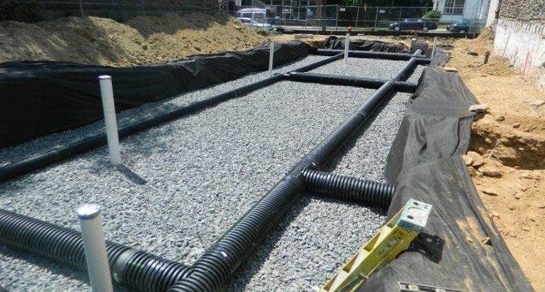
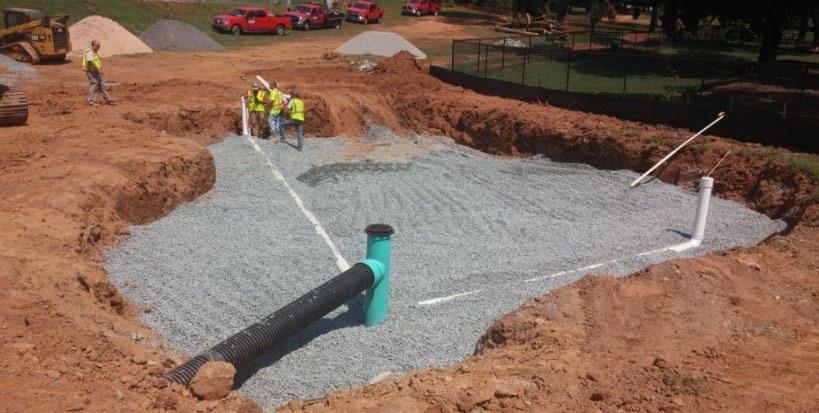
5.15.3 Internal Water Storage (IWS) Design
There are two approaches to creating an IWS within an SCM: an upturned elbow underdrain (shown in Figures 5.15.1.2 and 5.15.2.1) and an IWS located below an elevated underdrain (Figure 5.15.1.3). in the latter configuration, the IWS is sometimes called an “infiltration sump.” Specifications for both approaches are provided in Table 5.15.3 1
Table 5.15.3.1 Internal Water Storage Specifications
Design Element Specifications
An upturned elbow underdrain design typically includes a 90-degree elbow located at the downstream end of the underdrain system. The elbow shall be located so that all upstream lines are subject to the IWS requirement.
Upturned Elbow Underdrain
Elevated Underdrain
Group 2 SCMs: A minimum of 12 inches of IWS shall be provided 2 Thus, the invert of the upturned elbow shall be a minimum of 12 inches from the invert of the underdrain line(s)
Group 3 SCMs: The invert of the upturned elbow is determined by the design professional based on the volume of IWS desired.
In vegetated SCMs of either group, the elbow invert (and thus the IWS) must be located well below (12 to 18 inches) the bottom of the planted area to reduce saturated conditions in the root zone.
In an elevated underdrain design, the underdrain lines are designed as specified in Table 5.15.2.1, except the stone jacket for the underdrain sits above the IWS area, which is filled with clean, doublewashed AASHTO #57 stone.
Group 2 SCMs: The IWS shall have a minimum thickness of 12 inches 3, measured from the bottom of the SCM excavation to the invert of the underdrain line
Group 3 SCMs: The thickness of the IWS layer is determined by the design professional based on the volume of IWS desired.
In vegetated SCMs, the IWS layer shall be located at least 12 inches below the bottom of the planted area to reduce saturated conditions in the root zone.
The IWS may be placed above an impermeable geomembrane if partial infiltration is not desirable. This configuration is suitable for SCMs located in karst areas.
2 Tennessee Department of Environment and Conservation Rule 0400-40-10-.04
3 Tennessee Department of Environment and Conservation Rule 0400-40-10-.04
Figure
Left: SCM installation with HDPE underdrain pipe and capped PVC observation wells (Source: Philadelphia Water Department); Right: A bioretention area under construction in Salem, NC. Note the upturned elbow underdrain and capped cleanouts (Source: Hazen and Sawyer)
5.16 Inlets, Energy Dissipation, and Pretreatment Measures
5.16.1 Introduction to Inlets and Energy Dissipation
design specification
Inlets are the structures or landscape features that manage the flow of stormwater into a stormwater control measure (SCM) Sometimes, their design is combined with an energy dissipator which slows the inflow rate to prevent erosion within the SCM itself. Inlets and energy dissipators can also be combined with a pretreatment measure, which is intended to capture heavy sediment, debris, and trash. Together, these SCM components manage the volume, rate, and cleanliness of flow entering the main treatment area of the SCM
Sections 5.16.2 through 5.16.4 address three non-standard inlets: curb openings; flow splitters; and energy dissipators Design information for standard inlet controls can typically be found in a local government’s street design (i.e., public works) standards.
5.16.2 Inlets - Curb Openings
Curb blocks and continuous curbing are popular methods to establish the SCM border and protect it from entry for SCMs located in or adjacent to parking lots and roadways (see Figure 5.16.2.1). When an SCM is bounded by a curb, openings are needed to allow stormwater to flow into the SCM. In continuous curbing applications, these openings are also called “curb cuts”. Curb openings can be implemented in an SCM design when standard inlet control and conveyance system structures are not feasible (due to space or other constraints) or desired. These designs have advantages and limitations, as shown in Table 5.16.2.1.
Table 5.16.2.1 Advantages and Limitations of Curb Openings
Advantages
Can reduce SCM depths and associated excavation and materials costs when chosen in lieu of inlets
Can be implemented as a strategy to reduce the concentration of stormwater flows into the SCM, thus reducing erosion potential
5.16.2.1 Example Curb Opening
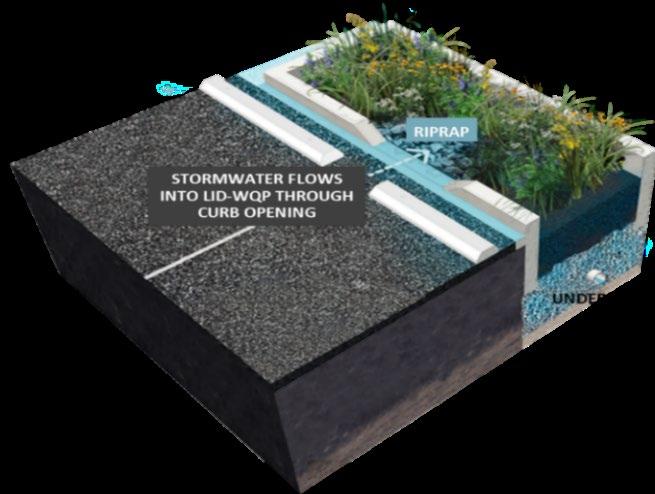
Limitations
Provides only limited control of bypass flows
May not be appropriate for large contributing drainage areas, or those with long flow paths over impervious areas, along driveways, or near roadways where a sump condition is not feasible
Design specifications for curb openings are provided in Table 5.16.2.2. Beyond these specifications, check with the local government to determine any further design requirements. Examples of curb opening designs are provided in Figure 5.16.2.2.
Table 5.16.2.2 Curb Opening Design Specifications
Design Element Specification
Elevation
Flow Design
The pavement edge at the curb opening must be higher than the elevation of the vegetated areas within the SCM, including any mulch layers that will be present, to avoid backflow from the SCM into the curb opening.
Curb openings must convey flow into an SCM without causing erosive conditions (flow velocity less than 5 ft/sec) Energy dissipators will likely be needed for curb openings since they concentrate flow and increase its velocity. See Section 5.16.3 for information on energy dissipators.
Figure
Northeast Tennessee Water Quality SCM
Design Element
Sizing
Location & Spacing
Roadway Material
Subsurface Material
Flood Protection
Safety Considerations
Specification
Curb openings must be designed to prevent bypass of gutter flow past the curb opening. This is a common problem with many curb openings that are oriented perpendicular to flow.
Curb openings must be sized to convey the design discharge into the SCM. Typically, openings range from 12 to 48 inches wide, with the following caveats:
Minimum curb opening width = 8 inches; this minimum width reduces clogging and provides for easier maintenance than smaller widths
Size curb openings appropriately for on-grade or sump conditions, whichever is appropriate
Curb openings are to be designed as gaps in otherwise continuous sections of concrete or granite curb conforming to the local government’s street standards
Trench drains can be used to convey flow from curb openings through sidewalks. See Figure 5.16.2.1 for an example.
Roadway materials and thicknesses must be able to withstand the appropriate loads at the edge and prevent undercutting.
All subsurface portions of concrete or granite curb (i.e., below finished pavement grade) must be continuously installed within the extent of the curb opening.
If curb openings are used to capture stormwater, especially from driveways or roadways where the curb openings are not in a sump condition, verification that stormwater from the 1-year, 24-hour storm event will be captured by the curb opening must be provided.
Pedestrian fall safety must be considered where a curb opening location is adjacent to or beneath sidewalks. The need for edge visibility and edge protection, such as railings or wheel stops, must be evaluated and accommodated
5.16.2.2 Examples of Different Curb Cut Designs
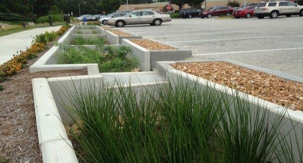
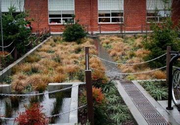
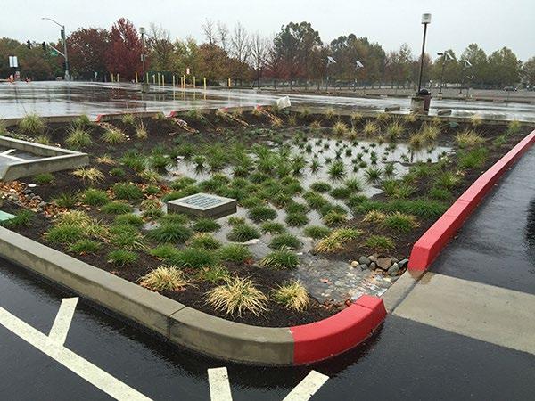

Figure
Top Left: A parking lot with curb cuts that allow stormwater into the bioretention areas (Mississippi Department of Marine Resources); Bottom Left: A trench drain directs stormwater into the curbed bioretention area (Chachula Design); Right: Curb cuts allow stormwater to enter a parking lot bioretention area (City of Sacramento, CA)
Northeast Tennessee Water Quality SCM Manual
5.16.3 Inlets - Flow Splitters
Flow splitters are inlet controls used to divert a fraction of stormwater (typically the water quality treatment volume [WQv]) to an SCM while bypassing larger flows to a downstream SCM (such as a conventional detention basin), onsite stormwater conveyance system, or receiving waterbody They may also have other applications where flow diversion/splitting is needed. The advantages and limitations of flow splitters are shown in Table 5.16.3.1. Example flow splitter layouts are shown in Figure 5.16.3.1.
Table 5.16.3.1 Key Advantages and Limitations of Flow Splitters
Advantages
Divide and divert the stormwater volume to alleviate downstream flooding during a storm or to prevent an SCM from exceeding its designed capacity
Reduce the cost of building an SCM by reducing the storage capacity needed to provide positive overflow
Enhance SCM longevity by reducing the volume of stormwater treatment and the amount of erosion, slope, and vegetation damage
Separate the WQv, which contains most of the stormwater pollutants, allowing it to be treated for a longer period of time without being diluted by additional stormwater, which can be diverted downstream or to another SCM
Figure 5.16.3.1 Example Flow Splitter Layouts
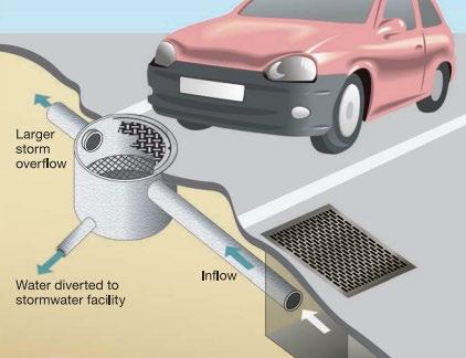
Limitation
Have the potential to cause flow reversal under certain circumstances (e.g., due to lack of backflow preventer or one-way valve) in which water will flow from an SCM back through the flow splitter
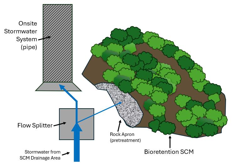
When applied as inlet controls, flow splitters are typically constructed by installing bypass weirs in inlets and utility holes (see Figure 5.16.3.2.a and b). On a larger scale, they can be constructed using concrete baffles in utility holes. Other designs that can route the design flow to the SCM and divert higher flows may also be acceptable.
Design specifications for flow splitters are described in Table 5.16.3.2. Materials specifications are provided in Table 5.16.3.3.
Left: Flow splitter shown in a drawing of a parking lot (Montgomery County, MD, Department of Environmental Protection). Right: Flow splitter directing WQv to a bioretention area (Mississippi Dept of Environmental Quality, Erosion and Sediment Control Manual, Vol. 2)
Northeast
5.16.3.2 Example Flow Splitter Designs (adapted from 2021 Kitsap County Stormwater Design Manual)

Manhole (no base channel required)


Handhold and steps or ladder access (may be needed on both sides of wall if > 36” high)
Water surface elevation of the design flow rate (typically, the water quality peak flow rate (Qwq)


Bypass pipe to detention basin or conveyance system
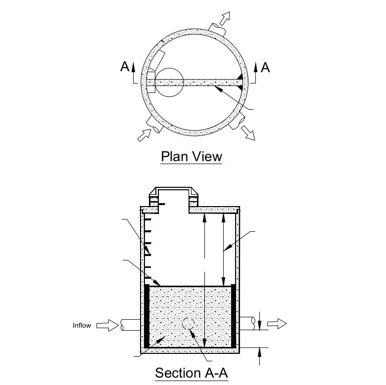
Figure 5.16.3.2.a

Reinforced baffle wall grounded to manhole structure on both ends


4 ft min., or provide separate access to either side of baffle wall 6” min.
Bypass pipe


Note: The outlet pipe to the SCM may require an orifice plate to control the water surface elevation (weir height) for the design flow rate [typically the water quality peak flow rate (Qwq)]. The water surface elevation of the design flow rate should be set to provide a minimum headwater/diameter ratio of 2.0 on the outlet pipe
Table 5.16.3.2 Flow Splitter Design Specifications

Inflow

Manhole (no base channel required)


Figure 5.16.3.2.b

Bypass pipe to detention basin or conveyance system


Diameter of standpipe (2 x diameter off outlet pipe recommended as a starting point for sizing)
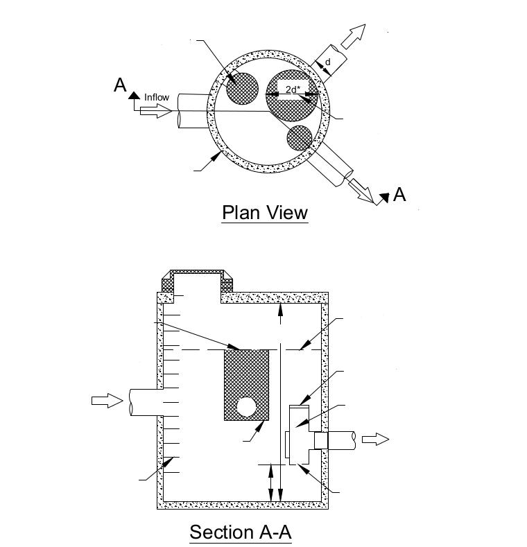

Top of riser at water surface elevation of the design flow rate
Solid top or extended to overflow water surface elev.

Half “tee” section with cleanout or removable bend-down elbow

To SCM

Orifice sized to pass the design flow rate to the top of bypass riser


Note: Diameter of standpipe (2d) should be large enough to minimize the head above the water surface elevation of the design flow rate [typically the water quality peak flow rate (Qwq)] and to keep water quality flows from increasing more than 10% during 100-year flows.
Specification
In Figure 5.16.3.2.a, the top of the baffle wall shall be located at the water surface elevation for the design flow rate (e.g., the water quality peak flow (Qwq), the maximum flow rate to stormwater wetlands, etc.)
The maximum head shall be minimized for flow in excess of the design flow rate. Specifically, flows to the SCM when at the 100-year water surface elevation shall not exceed the design flow rate by more than 10%.
In Figure 5.16.3.2.b, an alternative to a solid top plate is a full tee section with the top of the tee at the 100-year water surface elevation. This alternative would route emergency overflows (if the overflow pipe were plugged) through the SCM rather than back up from the utility hole.
Special applications, such as SCMs adjacent to roads, may require the use of a modified flow splitter where the baffle wall in Figure 5.16.3.2.a is fitted with a notch and adjustable weir plate to proportion stormwater volumes rather than high flows.
Backwater effects shall be considered in designing the height of the standpipe in the utility hole or vault flow splitter structure.
Ladder or step and handhold access shall be provided. If the baffle wall in Figure 5.16.3.2.a is higher than 36 inches, two ladders shall be provided, one on each side of the wall.
Figure
To SCM
Design Element
Utility Hole or Vault Type 2
Baffle wall
Metal parts
5.16.4
Specification
Reinforced concrete or another suitable material resistant to corrosion
Minimum thickness = 4 inches
Minimum clearance between the wall and bottom of the utility hole cover = 4 feet; this distance can be smaller if dual access points are provided.
All metal parts (e.g., weir or orifice plate) shall be corrosion resistance. Preferred materials include aluminum, stainless steel, or use a sturdy plastic. Zinc and galvanized materials and painted metal or plastic are prohibited due to aquatic toxicity.
Energy Dissipators
Energy dissipators are devices or practices designed to reduce the velocity, energy, and (sometimes) turbulence of flow. These structures can be employed when highly erosive velocities are encountered at the end of flow inlets, outlets, culverts, and at the bottom of steep slopes. They are required at the inlets of most SCMs. Energy dissipators include, but are not limited to, rock aprons (also called “splash pads”), riprap basins, and baffled dissipators.
Rock aprons are commonly used for energy dissipation due to their relatively low cost and ease of installation. A flat rock apron can be used to slow and spread the flow, thus reducing the inflow energy. Rock aprons are a popular choice to prevent erosion at the transition from an inlet into a forebay or SCM. They will provide adequate protection against erosive flows, provided there is sufficient length and flare to dissipate energy by expanding the flow. Rock apron examples are shown in Figure 5.16.3.2.
Riprap basins are pre-shaped scour holes lined with riprap that function as energy dissipators. Like a riprap apron, a riprap basin can be used to prevent erosion at flow transitions. Riprap basins are more commonly used in SCMs that serve large drainage areas and provide both water quality and quantity control, such as extended detention basins, water quality basins, and stormwater wetlands.
Baffled dissipators, such as a Hook Type Energy Dissipator Basin, are concrete or fiberglass boxes containing an alternating series of baffles and/or chambers. In addition to reducing flow velocity and energy, this energy dissipator can effectively remove sediment, suspended particles, and associated pollutants from stormwater. Baffled outlets are typically used for much larger stormwater applications but have been successfully applied in SCMs.
The advantages and limitations of energy dissipators are presented in Table 5.16.4.1. Design specifications for energy dissipators are detailed in Table 5.16.4.2
Table 5.16.4.1 Key Advantages and Limitations of Energy Dissipators
Advantages
Reduce velocities of concentrated stormwater flow
Reduce erosion potential and allow for more efficient sediment removal efforts, reducing overall maintenance costs and improving SCM performance
Prevent scour that may undermine the structure discharging concentrated stormwater runoff
Prevent downslope erosion that may create gullies and scour holes
Limitations
May increase erosion if not properly designed and installed
Table 5.16.3.3 Flow Splitter Materials
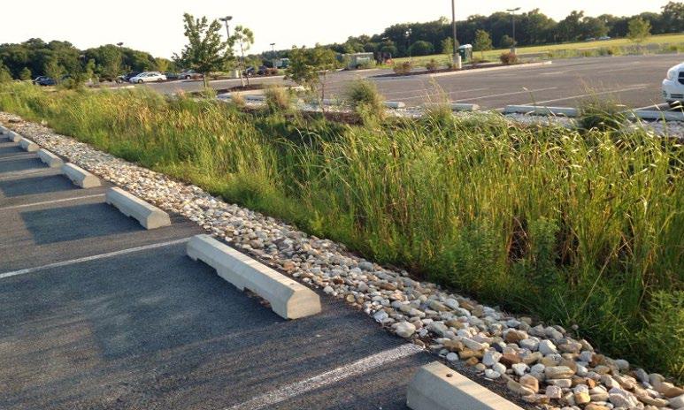
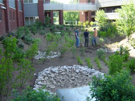
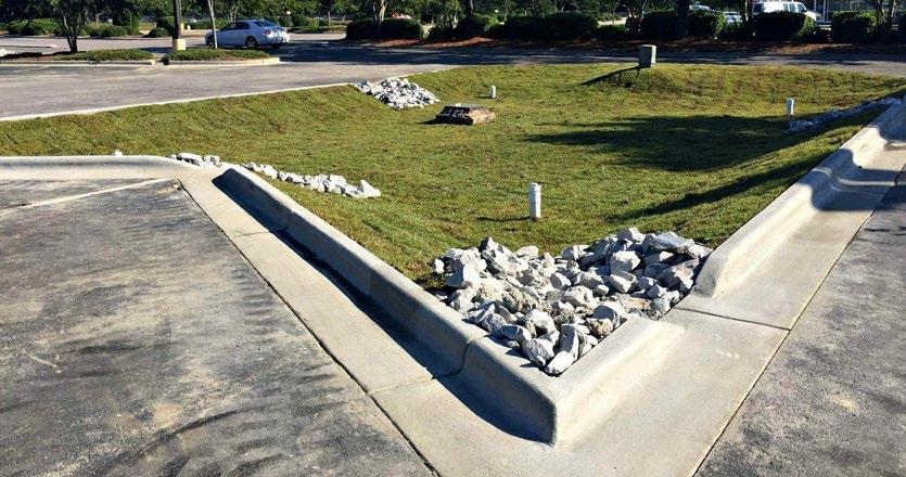
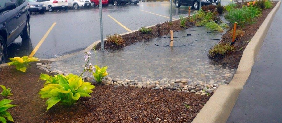

Table 5.16.4.2 Energy Dissipator Design Specifications
Design Element
Selection
Flow
Vegetation Interface
Rock Apron Design
Riprap Basins & Other Energy Dissipators
Aesthetics
Specification
Select an appropriate energy dissipator type based on site characteristics such as slope, available area, and aesthetics.
Energy dissipators must be used if the flow is concentrated at the inlet to an SCM and/or has a flow rate greater than 5 ft/sec
The design professional is referred to the United States Army Corps of Engineers, Hydraulic Engineering Center Circular 14 (HEC-14) for the design of alternate types of energy dissipators, such as drop structures and stilling basins.
A key design issue is the interface between the end of the energy dissipator and the adjacent downstream area, which is typically vegetated. Vegetation should be well established at this interface. Turf reinforcement matting may be used at this interface to provide additional structure for vegetation.
Rock apron design shall be in accordance with the riprap apron design for culverts provided in the latest edition of the Tennessee Department of Transportation (TDOT) Drainage Manual
The design of riprap basins and other energy dissipators shall be in accordance with the energy dissipation chapter provided in the latest edition of the TDOT Drainage Manual
Decorative landscape rock may be used in place of riprap for rock aprons (not riprap basins or other energy dissipators), provided the rock is of sufficient size to not dislodge in the highest flows expected from the SCM inlet.
Figure 5.16.4.1 Example Riprap Aprons
Top left: Perimeter rock apron in a bioretention SCM (NJ Stormwater Management BMP Manual); Lower left: A riprap basin in a newly planted bioretention SCM; Top right: Riprap aprons at curb cut inlets to an infiltration basin (both pictures from NCDEQ Stormwater Design Manual); Lower right: Stone lined inlet aprons in a movie theater parking lot bioretention area (wiki.sustainabletechnologies.can)
Northeast Tennessee Water Quality SCM
Design Element
Baffled or Other Energy Dissipators
Specification
Vegetation may be used to obscure views of energy dissipation structures if aesthetics is a concern. However, avoid the use of woody vegetation and wandering vines near inlets, energy dissipators, and pretreatment devices as they can obstruct flow, cause component damage, and create maintenance difficulties.
For stream outfalls, the energy dissipation design tools from the Federal Highway Administration (FHWA), HEC-14, HEC-15, and HEC-23 (which supersedes former HEC-11) must be used for riprap, energy dissipators, and flexible linings, respectively.
5.16.5 Pretreatment Measures
Pretreatment measures are critical to SCM maintenance and must be included in every structural SCM. This is especially true for infiltration based SCMs, such as bioretention areas, urban bioretention areas, and infiltration basins These SCMs operate through soil or gravel infiltration and filtration, they are more sensitive to clogging by sediment accumulation than traditional SCMs, such as an extended detention pond. Properly designed pretreatment measures will sustain the water quality management function, extend the service life, and reduce the maintenance costs of SCMs.
There are a variety of pretreatment measures available to design professionals. All of them function by decreasing peak stormwater velocities and allowing solids and sediment to be removed via filtering (through vegetation) or settling before the stormwater enters the main treatment area of the SCM (see Figure 5.16.5.1). Some design professionals prefer to use hydrodynamic manufactured treatment devices (MTDs) or proprietary pretreatment devices (PPDs) for pretreatment purposes. Regardless of the pretreatment measure used, all capture debris in focused or hidden areas, ideally providing for easy cleaning. This tends to also improve SCM aesthetics if the main treatment area, which can be the focal point of the SCM, is kept clean and free of litter, trash, etc.
This design specification describes a variety of options for pretreatment measures. However, design professionals should not feel limited to only the options provided. The necessity for stormwater pretreatment varies according to the specific circumstances of the proposed development, including the pollutants and pollutant volume(s) expected, nature of flow (diffuse or concentrated), space limitations, design, and aesthetics. If the design professional can demonstrate compliance with the requirements of this section, alternate pretreatment designs may be accepted.
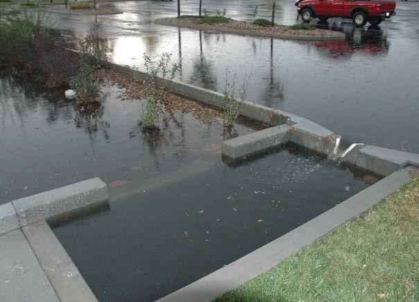
A small concrete forebay, as shown in the foreground, slows stormwater inflows substantially to allow most of the sediment to settle out of the water before it flows into the main treatment area of the SCM
The pretreatment measures designed should fit the situation at hand. For example, vegetated filter strips are typically better suited for diffused stormwater flow, while forebays and MTDs are better suited for concentrated stormwater flow. However, other factors must be considered. For instance, SCMs located in a fastfood development will likely see a high volume of floating debris (cups, lids, straws, cartons, wrappers, etc.) but will also be constrained due to limited space. In this case, vegetated filter strips or grass channels are probably not suitable; they are better for filtration of smaller pollutants (e.g., sediment, cigarette butts, etc.) and will probably take up too much space for a typical fast-food development lot size. A hydrodynamic MTD may be more appropriate for this situation. Even so, the MTD will likely require frequent cleaning to prevent clogging. For a fast-food restaurant, a pretreatment device combined with

Figure 5.16.5.1 Example of a Pretreatment Forebay (Source: Urban Water Center)
Northeast Tennessee Water Quality SCM Manual
appropriate good housekeeping measures (e.g., outdoor trash cans and frequent trash pickup by employees) is the best approach.
5.16.6 Applicability Guidance
Table 5.16.6.1 provides guidance on the typical applicability of typical pretreatment devices
Table 5.16.6.1 Pretreatment Measure Applicability
5.1 Bioretention
5.2 Cistern A pretreatment measure is usually included in the design of this SCM
5.3
5.4
5.5
5.6
5.7 MTDs A pretreatment measure is usually included within the MTD unit
5.8 Permeable Pavement System Pretreatment devices are not usually provided.
5.9
5.10
5.11 Submerged Gravel Wetland
5.12
5.13
5.14 Water
1 PPDs are different from manufactured treatment devices (MTDs). MTDs are structural SCMs that can be used, alone, to meet the local government requirements for stormwater treatment or can be used as pretreatment. PPDs cannot be used to meet stormwater quality treatment standards by themselves.
5.16.7 General Policies
The following general policies apply to the use of pretreatment measures with structural SCMs:
1. Pretreatment required. Pretreatment of stormwater inflows is specified for most SCMs. Consult the design specification in Chapter 5 for the selected SCM to determine whether pretreatment is specified. When pretreatment is specified in a SCM design specification, it must be provided at every inlet to the structural SCM, unless otherwise established in the SCM’s design specification.
2. Pretreatment measure documentation. Pretreatment measures are NOT considered stand-alone SCMs. Rather, they are considered a component of the structural SCM and thus shall be fully included, shown, described, and otherwise addressed in the water quality management plan (WQMP), record drawing, and any other required
Northeast Tennessee Water Quality SCM
documents for design, post-construction, or structural SCM operation and maintenance purposes. Pretreatment measures are required to be maintained in the same manner as the structural SCM itself.
When hydrodynamic MTDs or other proprietary devices are used for pretreatment purposes, the manufacturer’s name and contact information, and the device’s make, model, size, design, and inspection, operation, and maintenance information provided by the manufacturer shall be provided in all required documents.
3. Pretreatment selection. Some SCMs specify a required type of pretreatment measure (i.e., a sediment forebay is the only pretreatment device allowed for detention basins, water quality basins, and stormwater wetlands) Otherwise, pretreatment measure selection and design shall take into consideration ease of maintenance and maintenance access.
4. Access requirements. Inlets, energy dissipators, and pretreatment measures are considered components of the SCM Thus, they shall be designed so all parts of it are readily accessible for inspection, cleaning, and maintenance, and must be included in the easement associated with the SCM
5.16.8 Sediment Forebays (Pretreatment Measure)
A sediment forebay is a small impoundment designed at inflow points of an SCM to dissipate the energy of incoming stormwater and allow for the initial settling of coarse sediments and capture of larger debris and trash. Sediment forebays are required for Group 3 SCMs that also provide water quantity storage (i.e., dry extended detention basins, water quality basins, and stormwater wetlands), but can be used for other SCMs as well.
Sediment forebays are located at locations of concentrated inflows; and are separated from the SCM’s main treatment area by an earthen, stone, or concrete berm located at the downstream end of the forebay Pretreated stormwater flows over the berm, or through a notch in the berm, and enters the main treatment area. This separation of the forebay and main treatment area aids in ease of maintenance and gross pollutant removal. Depending on the design, forebays can provide both pretreatment and energy dissipation (see Figure 5.16.2.2). Forebays are usually designed as surface features (addressed in this section) but can also serve in underground configurations.
There are many variations of forebays, including: small shallow detention areas, deeper stilling-well types of areas; shallow areas with baffles, boulders, or cobbles that stormwater flows through; and drop gravel trenches/level spreaders. Forebay design is not limited to the examples shown or described herein. Rather, design professionals have the flexibility to design forebays in ways that fit their site, provided the design considerations identified in this Section are addressed. Successful water quality management plans will combine appropriate materials and designs specific to each site.
5.16.8.1 Rock Forebay (Source: Water Conservation Technologies)
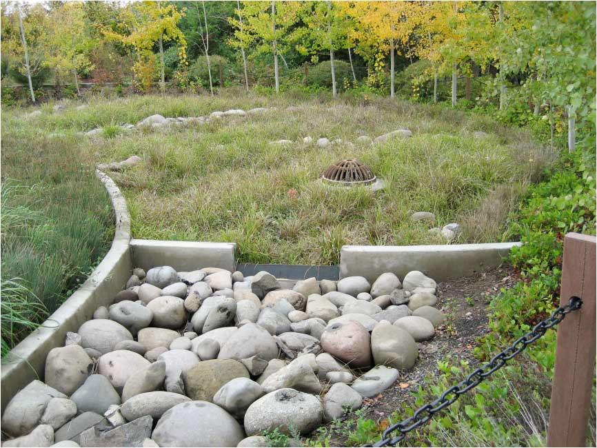
A bioretention area’s forebay (also rock basin or rip rap basin) is shown in the foreground. Stormwater flows through the boulders, removing trash and debris, before entering the SCM’s main treatment area.

Table 5.16.8.1 lists the advantages and limitations of forebays. Figure 5.16.8.2 shows examples of different forebay designs.
Figure
Table 5.16.8.1 Key Advantages and Limitations of Forebays
Advantages
Effective at removing coarse sediment and debris from small frequent storm events
Helps define the space and awareness of the SCM
Easy to vary the design and aesthetic yet still retain the desired function(s)
Figure 5.16.8.2 Other Forebay Examples
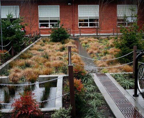
Limitations
Generally ineffective at fine particulate removal
Requires more land than most other pretreatment measures
Usually visible to passersby, and therefore can create aesthetic concerns if not cleaned regularly
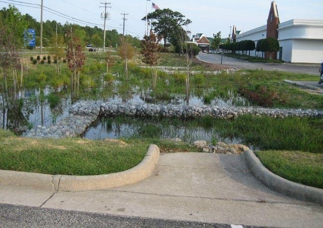
Left: A creative approach to forebay and inlet design is shown with the stilling-well type of forebay shown in the foreground on the left (source: Chachula Design); Right: A large forebay created by rip-rap gabion baskets, shown in the foreground of the picture, pretreats stormwater before it discharges to the main treatment area of the engineered wetland (Source: Center for Watershed Protection).
Table 5.16.8.2 provides design specifications for forebay pretreatment measures. Additional policies and considerations follow the table, as well as a schematic of a shallow forebay in Figure 5.16.8.3. The use of “shall” indicates a design requirement that will be enforced by the local government. All other statements are to be considered as non-mandatory guidance.
Table 5.16.8.2 Forebay Design Specifications
Forebays for Group, Group 2, and non-storage Group 3 SCMs (e.g., sand filters) can be created with excavation (or with limited excavation) by placing a berm on the downslope side of a mild slope, provided stormwater does not overflow the sides of the forebay and flows only over the berm for the water quality storm rainfall.
This design generally will not be effective in forebays for Group 3 storage SCMs [i.e., dry extended detention basins, stormwater wetlands, and stormwater (wet) basins], as they are required to be much deeper than can be afforded by a mild slope. Excavation is required for forebays designed within Group 3 storage SCMs.
Inlet Control
Forebay inlets must include riprap aprons, stone placed in concrete, or some other type of energy dissipation device to rapidly reduce the inflow velocity for erosion/scour protection, provide separation of gross solids and floating debris, and encourage settlement of suspended solids.
Northeast Tennessee Water Quality
Design Element
Volume/Sizing
Liner
Berms
Sediment Depth
Maintenance
Forebay discharge
Specification
Forebays designed for use in Group 3 storage SCMs [i.e., dry extended detention basins, stormwater wetlands, and stormwater (wet) basins] shall have a minimum storage volume of 10% of the water quality volume (WQv).
For all other SCMs, forebays shall have a minimum storage volume of 0.1 inch per impervious acre.
Forebay sizing shall consider an expected level of sediment loading. Where high volumes of sediment are anticipated, a deeper or larger forebay may be necessary. (Note: Some SCMs, and especially Green Infrastructure (GI)-SCMs, are not suitable for use where high volumes of sediment are expected.) Drainage area size and characteristics have an impact on the nature and frequency of maintenance activities and corresponding long-term performance. For example, large parking lots deliver more sediment to an SCM than rooftops. Therefore, forebays that receive drainage from large parking lots may require a different design than those that receive stormwater from rooftops only.
Sediment forebays for Group 3 SCMs shall be lined with concrete (preferred) or large rocks. Concrete is preferred because it affords easier removal of deposited sediment, trash, and debris in the future.
The preferred lining for forebays in Group 1 and 2 SCMs is concrete, but they may also be lined with rocks, dense grass, or other dense vegetation ground cover.
Vegetation within forebays can help to improve aesthetics and assist with pollutant removal; however, high velocities and high rates of sedimentation within forebays can make vegetation survival difficult. Also, vegetated forebays require more frequent cleaning to ensure vegetation is not covered from sunlight by deposited sediment, trash, and debris for long periods. Seed mixes used in vegetation forebays must be appropriate for the underlying soils and be able to withstand occasional inundation by stormwater. Stormwater shall be prevented from entering vegetated forebays (and the main treatment areas of the SCM) until the entire forebay is fully and permanently stabilized from potential erosion.
Prohibited linings for forebays in all SCM types include bare soil and ground cover materials that are easily dislodged by flowing water (e.g., mulch, pebbles, river rock).
A berm must physically separate the forebay from the main treatment area of the SCM. The berm should span the entire width of the SCM and shall be constructed of stone, concrete, or other solid material Earthen berms are prohibited. An outlet control, such as a weir, may be needed to drain the forebay to the main treatment area of the SCM.
Forebays designed for use in Group 3 storage SCMs [i.e., dry extended detention basins, stormwater wetlands, and stormwater (wet) basins] shall include permanent vertical markers constructed of durable materials that must be installed within the forebay area to indicate the sediment depth.
Inspection and maintenance access is most commonly provided via stabilized and mildly sloping graded areas that can be accessed by heavy equipment.
The exit velocities from the forebay into the main treatment area must be non-erosive, maximum velocity of five (5) ft/sec.
in a Bioretention Area
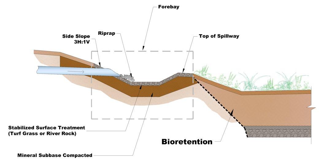
5.16.9 Vegetated Filter Strips
Vegetated filter strips are densely vegetated areas that provide both energy dissipation for small storms and stormwater pretreatment. They treat stormwater from adjacent pervious and impervious areas by slowing stormwater velocity and filtering some pollutants before stormwater enters the main treatment area of an SCM (see Figure 5.16.9.1). They are a pretreatment measure typically applied within bioretention areas, dry enhanced swale, and infiltration basin SCMs, but can be used as grass channels for shallow flows. They may infiltrate a small amount of stormwater; however, this is usually negligible and should not be considered to reduce the design volume of the main treatment area of the structural SCM.
Shallow, dispersed flow is required for pretreatment using a vegetated filter strip. In fact, filter strips treat stormwater only in sheet flow. A grass swale is a variation of this pretreatment measure, consisting of a gently sloped, densely grassed, very low-flow channel. Grass swales can pretreat water in shallow concentrated flow. However, neither configuration will provide pretreatment for concentrated flow.
Vegetated filter strips and grass swales are generally sensible and cost-effective stormwater pretreatment options applicable to a variety of development sites and structural SCMs. Their designs are not limited to the examples shown within this text.
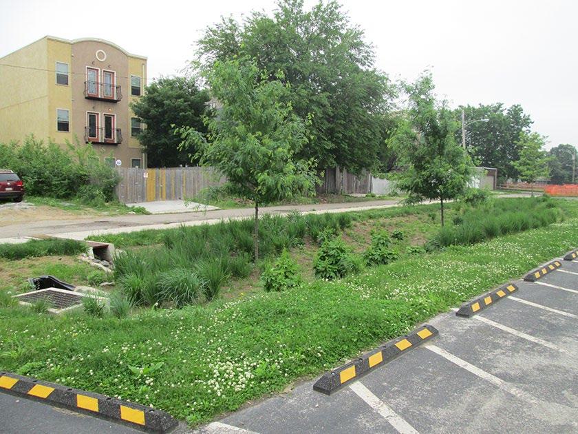

The advantages and limitations of filter strips are shown in Table 5.16.9.1
Figure 5.16.8.3 Schematic of a Forebay
Figure 5.16.9.1 Example of Grass Filter Strip (Source: Philadelphia Water Department)
A densely grassed vegetated filter strip is located between the parking lot and main treatment area of the SCM. Sheet flow from the parking lot flows through the filter strip before it enters the SCM.
Table 5.16.9.1 Key Advantages and Limitations of Vegetated Filter Strips
Advantages
Effective at removing coarse sediment, fine particulates, and small debris/trash (e.g., cigarette butts) from small frequent storm events
Flexible design allows application in many situations
Easy to design, construct, and maintain
Low-cost pretreatment measure
Limitations
Generally ineffective at removing large debris and floating debris
Requires erosion prevention and plant maintenance
Can require more land than other pretreatment measures (depends on situation)
Usually visible to passersby, and therefore can create aesthetic concerns if not cleaned regularly
Table 5.16.9.2 provides design specifications for vegetated filter strip pretreatment measures. The use of existing vegetated areas that have surface features that disperse stormwater is encouraged, as the use of these areas will also reduce overall site disturbance and soil compaction. An example schematic of a vegetated filter strip is provided in Figure 5.16.9.3.
Table 5.16.9.2 Vegetated Filter Strip Design Specifications
Design Element
Drainage Area
Length
Inflow
Specification
The maximum contributing drainage area that discharges through a filter strip or grass swale shall be less than five (5) acres and must not exceed a drainage area to filter strip/grass swale area ratio of 6:1.
The “contributing flow path” is defined as the maximum length of the flow path in the area draining to the vegetated filter strip or grass swale.
For contributing flow paths less than 30 feet in length, Figure 5.16.9.2 must be used to determine the filter strip length. The length requirements shown are scaled from the dimensions of a grassy vegetative swale for the same slope and flow conditions identified below:
Required Starting Design Values for Filter Strip Length
Strip length perpendicular to flow path
Strip length parallel to flow path
Longest length feasible
Four (4) feet* to 150 feet
*The minimum pretreatment filter strip length is based on the length of the receiving flow path. Figure 5.16 9.2 shows how the minimum length requirement changes as both the flow path and filter strip slope change.
For contributing flow paths greater than 30 feet in length, the required flow characteristics for maximum velocity and depth listed below must be used:
Required Starting Design Values for Filter Strip Length
Maximum velocity
Maximum water depth
One (1) ft/sec max, < 0.5 ft/sec preferred
One (1) inch max, < 0.5 inch preferred
Source: United States Department of Transportation (USDOT) Stormwater Best Management Practices in an Ultra-Urban Setting: Selection and Monitoring and the Seattle BMP Manual
Flow must enter a vegetated filter strip as sheet flow.
Flow must enter a grass swale as sheet flow or shallow concentrated flow.
Concentrated flow can erode the soil and cause the pretreatment measure to be ineffective. If the flow is concentrated, design a level spreader to provide sheet flow
Design Element
Slope
Energy Dissipation
Plant Selection and Installation
Protection Measures
Enhancements
Specification
The maximum contributing drainage area slope must be less than 5% unless energy dissipation and/or flow spreaders are provided up-gradient of the filter strip.
The filter strip slope must not exceed 8%. Slopes less than 5% are generally preferred. Filter strips with slopes that exceed 5% should implement check dams to encourage ponding and prevent scour and erosion of the filter strip area.
The slope (parallel to the flow path) of the top of the filter strip, after a flow spreading device, must be very flat (less than 1%) and gradually increase to the designed value to protect from erosion and undermining of the device.
When energy dissipators or level spreaders are not included in the design, the maximum allowable flow path to a vegetated filter strip is 75 feet for impervious ground cover and 150 feet for pervious ground cover.
When energy dissipators or level spreaders are included, the flow path can be increased beyond the above-stated maximums provided shallow, dispersed flow having a velocity of less than 5 feet per second is maintained.
Vegetated filter strips and grass swales shall be entirely vegetated with dense native grass or other dense, non-woody, vegetated ground cover that does not require substantial maintenance or mowing. The planting regime should be as dense as the soil conditions can sustain. This is especially true at the top portions of the filter strip where the highest sheet flow velocities are found. Soils that can sustain higher quantities and qualities of vegetation may need to be added to ensure the thick vegetative densities needed for sustainable filter strip performance.
Turf grass is generally not recommended because it is maintained by frequent mowing. Cut grass reduces the potential for contact between vegetation and pollutants, thus reducing pretreatment (i.e., filtration) effectiveness.
Areas of bare soil are prohibited. Mulch, pebbles, and other non-vegetated ground cover materials are prohibited.
Trees and shrubs may be allowed in the flow path if the filter strip exceeds the minimum length requirements.
It is critical that plants used in vegetated filter strips and grass swales are appropriate for soil, hydrologic, light, and other site conditions. Ponding depth, drain-down time, sunlight, salt tolerance, soil infiltration capacities, pollution tolerances, root structure, and other conditions must be taken into consideration when selecting plants.
Plants must be established at the time of filter strip completion (at least three [3] months after seeding). No stormwater shall be allowed to flow across the filter strip and into the main treatment area of the SCM until the vegetation is fully and permanently established.
Filter strips shall not be used in highly used pedestrian areas unless precautions are taken to minimize disturbance of the filter strip, such as signage, fences, and placement of sidewalks or paths to minimize pedestrian or vehicular traffic.
Vegetated filter strips may be enhanced by installing berms and retentive grading perpendicular to the flow path. A pervious berm and/or retentive grading allows for a reduction in both stormwater velocity and volume, thus improving pollutant removal capabilities by providing a temporary (very shallow) ponded area.
5.16.9.3 Schematic of a Vegetated Filter Strip (Source: adapted from the Seattle Stormwater Manual Vol. 3, 2008)
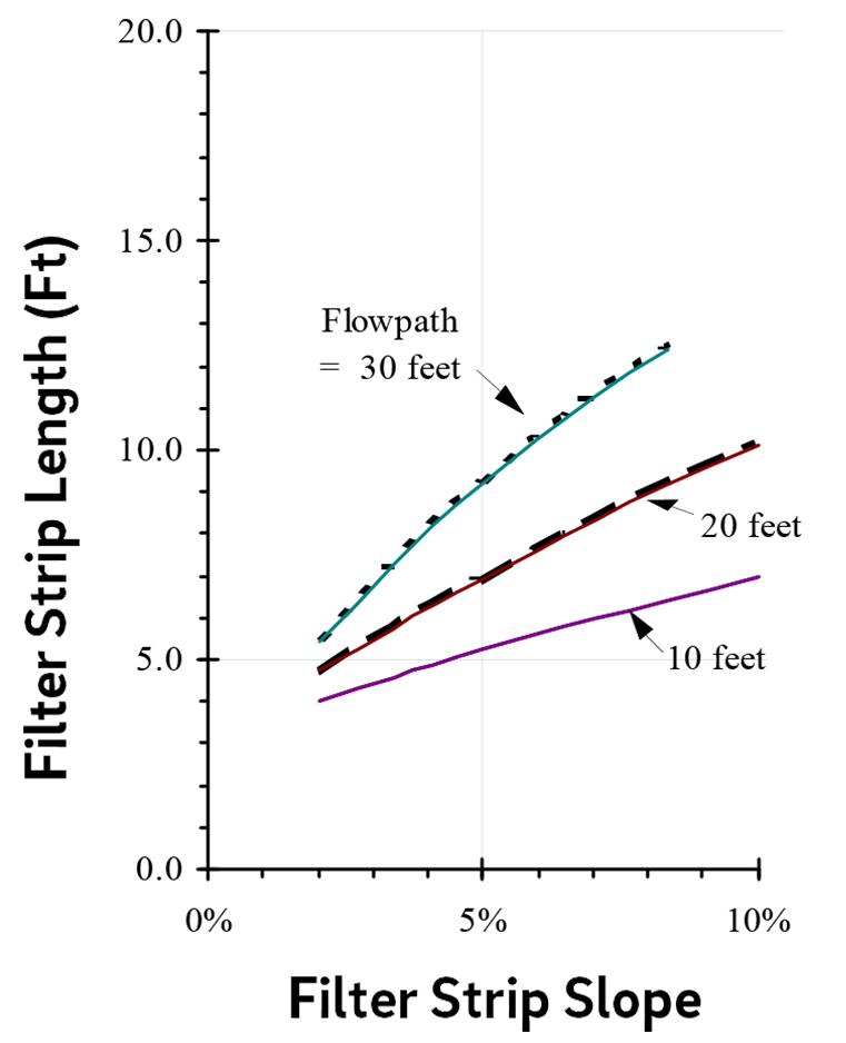
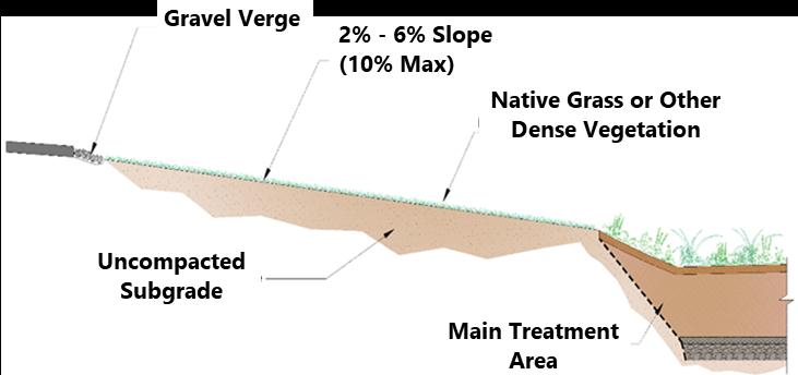
5.16.10 Proprietary Pretreatment Device
A proprietary pretreatment device (PPD) is a manufactured device that can be included in structural SCM designs specifically for the purpose of stormwater pretreatment. There are several types of PPDs on the market that combine both the inlet structure and pretreatment measures. PPDs are generally easy to install and maintain (see Figures 5.16.10.1 and 5.16.10.2).
5.16.10.1 Example of a Proprietary Pretreatment Device (Source: Rain Guardian)
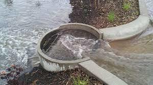
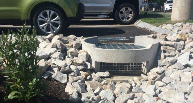
5.16.10.2 Installation of a Proprietary Treatment Device (Source: ACF Environmental/PRETX system)
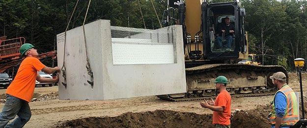
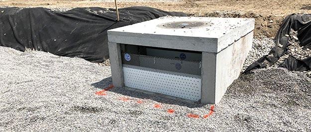
Figure 5.16.9.2 Filter Strip Length
Figure
Figure
Figure
The PPD shown in the pictures facilitates easy inspection and maintenance. Sediment can be removed from the chamber with a shovel, and the dropin filter can be cleaned with a broom or hose
PPDs work well as pretreatment practices for most SCMs, especially where space constraints do not allow for larger pretreatment measures such as forebays or vegetated filter strips. The individual PPD specifications should be consulted on a site-by-site basis to ensure they are feasible for the proposed application. The manufacturer’s specifications must be consulted to determine the device-specific requirements and applicable SCMs.
PPDs are different from manufactured treatment devices (MTDs). MTDs are structural SCMs that can be used, alone, to meet the local government requirements for stormwater treatment. Hydrodynamic MTDs are a popular choice for pretreatment in jurisdictions that have a specific pollutant removal threshold, as their small surface footprint is helpful for space-limited areas. In contrast, PPDs are specifically intended to provide pretreatment for the primary SCM selected for a drainage area. PPDs cannot, alone, meet the local government’s stormwater quality requirements.
See Chapter 5, Section 5.7 of this manual for more information and design specifications for MTDs, including the use of hydrodynamic MTDs used as pretreatment devices.
5.17 OVERFLOW CONTROLS
5.17.1
Introduction
design specification
Overflow controls are designed to allow excess stormwater flows to exit the stormwater control measure (SCM) when the capacity of the SCM is exceeded. Overflow control can be designed to control water levels both at the surface and in the subsurface of the SCM. Stormwater above the finished grade of the SCM is controlled with an overflow structure or a weir that is overtopped once the ponding elevation in the SCM is exceeded. The overflow control conveys flows away from the SCM to a downstream stormwater conveyance system. This section does not address storage facility outlet structures (refer to Chapter 3, Sections 3.5.1 to 3.5.9), underdrains and internal water storage (refer to Chapter 5, Section 5.15), or emergency spillways (refer to Chapter 3, Section 3.5.10).
5.17.2
Description
Overflow controls are commonly employed in green infrastructure (GI) stormwater control measures (SCMs), enabling excess stormwater to bypass the subsurface media by overflowing the GI-SCM. Overflow controls can consist of solid plastic pipe and fittings, a manufactured structure with a grated cover, or an overflow weir that extends above the finished grade of the GI-SCM to collect stormwater from the GI-SCM surface. When the design ponding elevation in the SCM is exceeded, the overflow conveys flows away from the GI-SCM to a downstream conveyance system. Overflow controls typically consist of the following types (see Figure 5.17.2.1):
1. Overflow Riser: Consists of a solid plastic pipe, usually polyvinyl chloride (PVC) or high-density polyethylene (HDPE) with a domed or flat grated top.
2. Manufactured Overflow Riser: Consists of prefabricated overflow control structure, it should be noted that manufactured overflow controls are often referred to by the manufacturer as “inlets” due to their stormwater collection function.
3. Overflow Surface Weir: Can consist of soil, stacked stone, concrete, or manufactured weirs located along the embankment or berm of an SCM. Weirs are discussed as part of the storage facility outlet structures in Chapter 3, Section 3.5
Overflow controls are necessary in SCMs that are not designed for flood control (i.e., will not manage storms larger than the 1-year, 24-hour storm event) as the stormwater inflows will, at times, surpass their design capacity. It is crucial to manage ponded elevation to avoid flooding areas adjacent to these SCMs. Overflow controls are most commonly used to control the ponded water surface elevation within SCMs.
5.17.2.1 Typical Overflow Controls for Tier 1 and Tier 2 SCMs
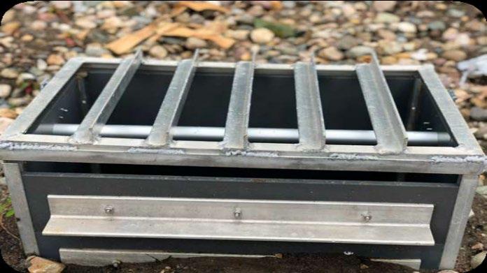
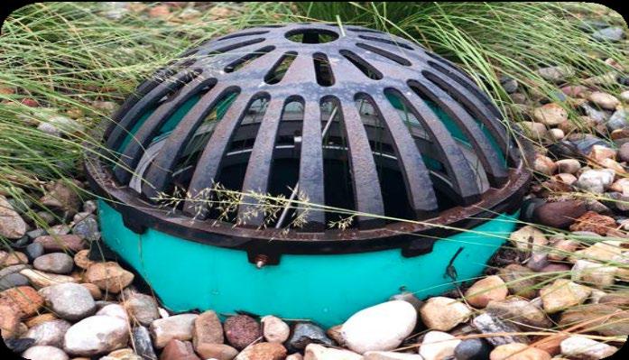
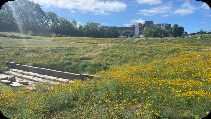
Figure
(Source: Kansas City, MO Green Stormwater Infrastructure Manual, 2022)
The overflow controls described in this section are meant for use with non-regional, on-site GI-SCMs and are not considered storage facility outlet structures (refer to Chapter 3, Section 3.5). In many cases, on-site SCMs do not warrant elaborate studies to determine overflow control capacity. While the risk of damage due to failure is a real one, it normally does not approach the catastrophic risk involved in the overtopping or breaching of a major reservoir. By contrast, regional facilities with homes immediately downstream could pose a significant hazard if failure were to occur, in which case emergency spillway considerations are a major design factor. Refer to Chapter 3, Section 3.5.10 for information on emergency spillway design.
5.17.3 Overflow Control Design Considerations
Table 5.17.3.1 provides guidance for site designers when designing overflow controls Refer to local government regulations for construction and material requirements.
Table
5.17.3.1 Overflow Control Design Considerations
Design Element
Elevation
Downstream Impact
Overflow System
Capacity
Overflow Risers
Design Consideration
Overflow elevations must be set at the design ponding height to avoid flooding of the SCM Any ponding above the overflow elevation is not recognized as part of the water quality volume (WQv) or any additional design storage volume in the SCM, as it discharges through the overflow control and bypasses the treatment provided by the SCM
The design professional must evaluate the potential impacts of outflow from the overflow control on the downstream drainage system by providing existing and proposed hydraulic grade line elevations.
For SCMs that are designed for WQv treatment alone, positive overflow must be provided for storm events larger than the water quality peak discharge, Qwq, up to and including the 100year, 24-hour storm.
Overflow controls and pipes must be designed to convey at least the peak discharge for the largest design storm included in the overflow. Typically, this will be the 25-year, 24-hour storm. The system must have enough capacity to transmit larger flows over the overflow control without surcharging the structure.
All local government design requirements for stormwater conveyance structures shall be met when designing overflow systems.
Overflow risers shall consist of two 45˚ elbow fittings to connect to outlet piping, when feasible. The two 45˚elbow fittings may be replaced with a 90˚ elbow or tee fitting when constrained by depth. An example detail for an overflow riser is provided in Figure 5.17.3.1.
The riser shall be topped by a dome or flat grate to prevent debris from entering the overflow riser. Consider ease of maintenance when selecting the grate.
Any metal components of an overflow riser embedded in concrete must be stainless steel.
An anchoring design for the overflow riser to mitigate flotation of the structure shall be considered, as needed.
Consider specifying a catch basket or strainer product within the overflow control to minimize debris exiting the facility.
Measures should be taken to minimize standing water in structure sumps to mitigate mosquito habitat.
Aesthetics of the portion of the riser that is exposed above grade should be considered. It is recommended that the exposed pipe be black or consider specifying decorative rock around the exposed pipe.
Design Element
Overflow Surface Weirs
Design Consideration
Design specifications and typical details for manufactured overflow risers shall be included with the water quality management plan (WQMP) and record drawing. Details are typically provided by the manufacturer.
Surface weirs should be sized, configured, and placed to control discharge over the weir and direct it to the desired flow path. Consider weirs with sharp crests, broad crests, notches, or of various shapes (e.g. rectangular or trapezoidal) to achieve such design objectives. Refer to Chapter 3, Section 3.5 for more information on weirs.
Surface weirs may be constructed of concrete, stone, or vegetated earthen berms. Select weir materials based on velocity, shear stresses, and hydrostatic pressure to prevent failure across the full range of anticipated flow conditions, as well as aesthetics and compatibility with the surrounding context.
Additional energy dissipation (See Chapter 5, Section 5.16) or stabilization is required on the downstream side of weirs to prevent scouring Earthen surface weirs should be well vegetated to prevent erosion and failure and may require additional stabilization.
Figure 5.17.3.1 Example Detail of an Overflow Riser
DOME OR FLAT GRATE
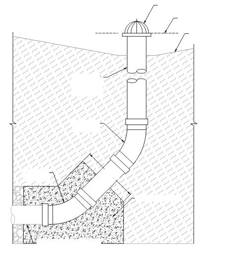


SCM DESIGN MAX. PONDING ELEVATION

SCM FINISH GRADE

5.17.4
References
ARC. Georgia Stormwater Management Manual Volume 2 Technical Handbook, 2016 Edition. Atlanta Regional Commission, 2016
City of Kansas City, Missouri. Green Stormwater Infrastructure Manual. October 2022.
CHAPTER 6: VEGETATED BUFFERS
6.3.1.
6.3.2.
6.4.
CHAPTER 6: VEGETATED BUFFERS
6.1 Introduction
A vegetated buffer, also called a “water quality buffer” or “buffer zone” is a use-restricted, permanent strip of dense, perennial vegetation located along the shoreline of a natural waterbody (see Figure 6.1.1) The area of dense vegetation protects the adjacent waterbody from polluted stormwater by infiltrating ponded stormwater and filtering overland stormwater flow The vegetation provides shade and stabilizes the streambanks and shoreline, which in turn provides a myriad of benefits:
Reduces the potential for bank/shoreline erosion and associated property damage;
Reduces sediment pollution caused by eroding banks/shorelines;

Reduces the potential for property damage when the waterbody experiences flooding;
Provides habitat for aquatic flora/fauna and shoreline wildlife;
Supports the chemical, physical, and biological integrity of the waterbody;
Minimizes public investment in waterbody restoration, stormwater management, and public water resource endeavors (Reynolds, 1999).
The Tennessee Department of Environment and Conservation (TDEC) Rule 0400-40-10 requires small Municipal Separate Storm Sewer Systems (MS4s) to implement and enforce requirements to establish, protect, and maintain permanent vegetated buffers at applicable land developments. Local government ordinances in Johnson City, Kingsport, Bristol, and Elizabethton, Tennessee set forth t he foundational requirements for buffer establishment in applicable new developments and redevelopments, and for protection and maintenance of all platted buffers. The ordinance also place restrictions on uses of, and materials and activities in, a platted buffer. Lastly, the ordinances refer to this manual for technical design specifications regarding buffer width and vegetation.
This chapter provides local government policies and guidance for the design and management of vegetated buffers. In addition, design professionals must adhere to the requirements, restrictions, and allowances for water quality buffers that are in local government ordinances.
6.2 Buffer Width
The required minimum buffer widths in terms of the minimum width at any location along a buffer and a minimum average width are shown in Table 6.2.1 The minimum width establishes the “inner zone” of the buffer, located adjacent to the buffered waterbody. Buffer width averaging is applied to the variable width “outer zone” located adjacent to, but upland of, the inner zone (see Figure 6.2.1). The width of the outer zone can vary, as long as the minimum (or a larger) average width is maintained along the length of the buffer. This method provides flexibility to accommodate developed areas located near the buffered waterbody. Regardless, property owners and design professionals are encouraged to establish buffers beyond the minimum width requirements included herein to further protect local water resources.
Figure 6.1.1 Vegetated Buffer on a Suburban
Source: PlanOKC Development Guide, 2024
Waterbody Characterization
Waters with available parameters for siltation and habitat alteration or unassessed waters.
Waters with unavailable parameters for siltation and habitat alteration or Exceptional Tennessee Waters
6.2.1 Vegetated Buffer Zones
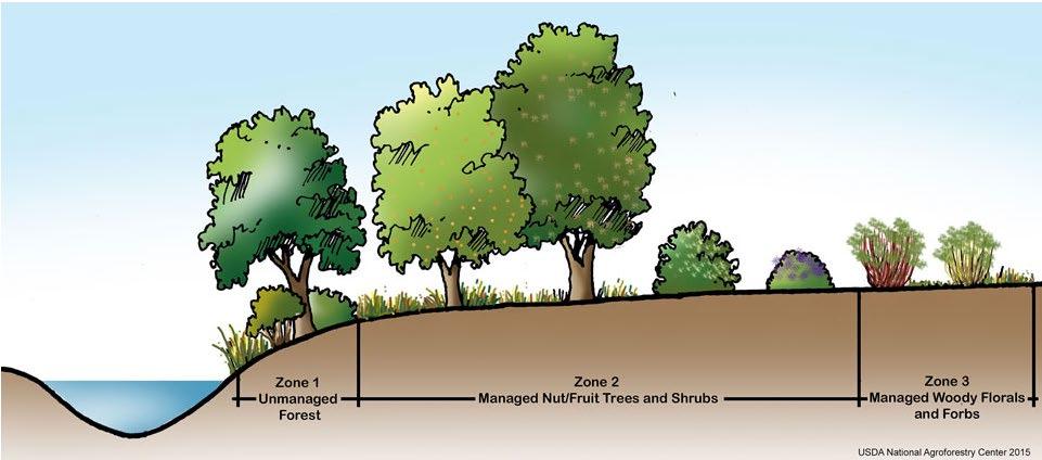

Policies and guidance for buffer width measurement and averaging are as follows
For streams, the buffer width shall be measured perpendicular to the top-of-bank of the active, natural stream channel. If the bank is not clearly defined, the width shall be measured perpendicular to the centerline.
For ponds and lakes, the buffer width shall be measured perpendicular landward from the topographic contour that defines the normal pool elevation.
For wetlands, buffer width shall be measured perpendicular from the outermost edge of the wetland as determined by the United States Army Corps of Engineers (USACE), the Natural Resources Conservation Service (NRCS), or TDEC.
The width of the inner zone of the vegetated buffer shall not be less than the minimum width identified in Table 6.2.1, except in the locations of approved stream crossings and utility corridors
Buffer width averaging can be applied in the outer zone to accommodate the development design provided the actual average width of the buffer equal s or exceeds the average width identified in Table 6.2.1
The average width is determined for the total length of streambank or shoreline located within the boundaries of the property to be developed, including the areas where stream crossings and utility corridors occur. If the development encompasses both sides of a stream, buffer width averaging can be used on both sides of the stream but must be applied independently.
Figure
Inner Zone (predominantly trees)
Outer Zone (herbaceous vegetation)
Adapted from USDA National Agroforestry Center, 2015
Impervious surfaces (e.g., pavement and rooftops) are limited within buffers. However, exceptions may be granted for impervious areas associated with stream crossings, utility corridors or substations, and trails or sidewalks. Design requirements are as follows.
Trails and sidewalks (herein referred to as pathways) composed of impervious materials (e.g., concrete, asphalt, packed gravel or earth) are allowed within a buffer provided the width of the zone in which the pathway is located is increased by the width of the pathway.
There shall be at least 1000 linear feet between stream crossings and at least 400 linear feet between access areas for utilities.
Crossings/corridors shall be no more than 15 degrees deviation from perpendicular to the waterbody bank/shoreline as to minimize clearing within the vegetated buffer. Allow sufficient room for installation and maintenance access
Examples of buffer width averaging for a vegetated buffer on a stream designated by TDEC as having unavailable parameters for siltation are shown in Figures 6.2.2 and 6.2.3
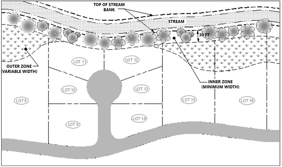
Figure 6.2. 2 Example of Buffer Width Averaging in a Residential Development
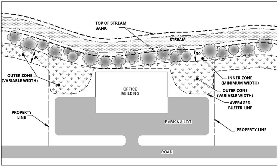
6.3 Buffer Vegetation
Vegetation within water quality buffers is critical to their effectiveness in removing pollutants from overland flows and providing habitat and shade along the bank or shore. Ideally, all water quality buffers would be comprised of a dense, undisturbed stand of trees with native, understory vegetation including immature trees, shrubs, and grasses. However, this ideal is not always desired by property owners in urban and suburban areas. Thus, the minimum requirements and guidance for buffer vegetation provide flexibility for a more “landscaped” buffer. Regardless, property owners are encouraged to avoid buffers that require significant landscape maintenance and allow vegetation within them to grow as undisturbed, natural areas.
6.3.1 Minimum Standards and Vegetation Growth Policies
Requirements for buffer vegetation are established below, along with additional vegetation policies and guidance.
Unless otherwise specified by local government ordinance, the predominant vegetation within the minimum buffer width area (inner zone) should be trees. The remaining buffer area (outer zone) may be composed of herbaceous vegetation (i.e., vascular plants that have little to no persistent woody stems above ground, such as grass), at a minimum. The herbaceous plants provide ground cover for erosion control and stormwater filtration. This standard is depicted in Figure 6.3.1.1. Mature trees and understory vegetation are encouraged in the outer buffer.
The introduction of invasive plant species, such as honeysuckle, privet, ivy and kudzu, and plants considered as nuisance, non-native (also termed “exotic”) is prohibited in and near the buffer. Native plant species are preferred throughout the buffer. See Section 6.3.2 (below) for resources pertaining to native and non-native plant species.
Areas of bare soil and erosion are not allowed in a vegetated buffer.
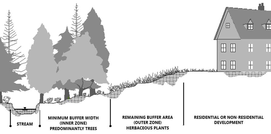
Permanent mulched areas are strongly discouraged in both buffer zones unless placed as a temporary erosion prevention measure while the buffer is constructed or maintained Vegetated ground cover, such as grass, is preferred as a permanent soil stabilization method. Non-vegetated ground covers (impervious surfaces, pavers, etc.) are prohibited, except when shown on an approved water quality management plan or with prior approval by the local government.
Water quality buffers that do not do not meet the vegetation standards established in policies 1 through 4 above can be restored through installation of trees and herbaceous vegetation. This may be required by the local government, especially if the existing vegetation within the buffer is unlikely to meet the standards through natural growth. For new developments or redevelopments, buffer restoration must be shown in the water quality management plan. The plan shall show:
the extent of the buffer zone(s),
existing vegetation to remain,
vegetation to be installed, and
best management practices for erosion prevention and sediment control during buffer restoration
Restoration activities shall be performed in accordance with any and all applicable local, State, and Federal permits. The property owner is responsible for obtaining such permits.
6.3.2 Additional Guidance
More detailed guidance and information on buffer enhancement and restoration, including appropriate species and plant installation techniques, can be found in the resources listed below.
The Tennessee Department of Environment and Conservation (TDEC) Riparian Buffers webpage: TDEC Riparian Buffers
TDEC’s Tennessee Urban Riparian Buffer Handbook
Tennessee Valley Authority (TVA) Shoreline Stabilization webpage: TVA Shoreline Stabilization
Tennessee Invasive Plant Council website: https://www.tnipc.org/
Chapter 6. Vegetated Buffers
6.4 Signs and Markers
Permanent signs or boundary markers may be required by the local government to ensure that adjacent property owners are aware of the buffer’s presence When signs/markers are required, they must be replaced when they are unreadable or have been removed or destroyed. The following general policies shall apply to buffer boundary markers
Locate signs/markers denoting the presence of a vegetated buffer on the lot lines at their intersection with the landward edge of the buffer, and at other locations which will approximately delineate the outer zone boundary with the remainder of the development (i.e., where it changes direction, etc.). For single lot site developments, signs/markers shall be posted every 100 feet along the buffer boundary. For subdivisions where multiple lots are located along the buffer, it is recommended that a buffer boundary marker be located at the intersection of every other lot line with the landward edge of the buffer.
Buffer signs/markers should be brightly colored and mounted at least 3 feet above the service to ensure their visibility and avoid damage. The post must extend below the ground surface at least 12 to 18 inches.

Figure 6.4.1 Vegetated Buffer Sign Template used in Nashville-Davidson Co., TN

At a minimum, signs/markers shall include the statement “Water Quality Buffer” at a reasonable font sized to allow reading from a distance of 10 feet. Additional information, such as “Do Not Mow” or educational messaging may be included.
6.5 Level Spreaders
6.5.1
Background
Level spreaders are structures that are designed to dissipate energy of concentrated flow and distribute it as sheet flow over a large surface area. For water quality buffers, they are used to maintain the function of buffers by transitioning concentrated flows of stormwater runoff into sheet flow. Water quality buffers are most effective for pollutant removal when shallow sheet flow is discharged to them. A shallow, sheet flow has a high surface contact area, increasing infiltration and the effectiveness of filtration. In contrast, concentrated flow can cause erosion in the buffer area, and limits the effectiveness of plants to filter out pollutants. Thus, the process of transitioning concentrated flows of stormwater into sheet flow is essential to maintaining the function and effectiveness of buffers that will receive stormwater runoff from adjacent areas.
An engineering detail of a typical level spreader is shown in Figure 6. 5.1.1.
Level spreader primary applications:
to disperse shallow concentrated or channelized stormwater runoff from impervious areas or upstream stormwater outfalls to a water quality SCM, such as a filter strip, water quality or other buffer, or other vegetated area; or,
for land draining to vegetated buffers that has more than a three percent (3%) slope: or,
for outlet diversion (i.e., the release of small volumes of concentrated flow from diversions when conditions are suitable).
Level spreader design elements:
A pipe, ditch, or swale through which concentrated flow enters the spreader;
An energy dissipator that slows the water;
Northeast Tennessee Water Quality SCM Manual
A level lip provided by the construction of a berm, concrete chute, or other permanent material or a shallow linear trench. The purpose of this component is to distribute runoff perpendicularly over the lip or through the trench at the same depth for the entire length of the spreader.
Figure 6.5.1.1 Detail of a Level Spreader Design
Source: City of Knoxville Land Development Manual, January 2001
JUTE NET OR EXCELSIOR MAT STAPLED IN PLACE AND ANCHORED 6" INTO GROUND
VEGETATION
MAXIMUM 10% SLOPE
LEVEL LIP FOR SPREADER (SEE NOTE 1) FLOW
SECURE WIRE MESH OR GABION TO RIGID LIP MATERIAL
COARSE AGGREGATE IN GALVANIZIED WIRE BASKET OR GABION
SECURE WIRE BASKET OR GABION TO GROUND WITH STAKES
MAXIMUM 10% SLOPE
GEOTEXTILE FILTER CLOTH
ENTRANCE WIDTH
END WIDTH
LENGTH = 10' TO 30'
ENTRANCE WIDTH
MINIMUM DEPTH
6' MINIMUM WIDTH
LEVEL SPREADER - VEGETATED LIP
ENTRANCE WIDTH
RIGID LIP MATERIAL (TYPICALLY LANDSCAPE TIMBERS)
#4 REBARS AT REGULAR INTERVALS TO ANCHOR LANDSCAPE TIMBERS
MINIMUM DEPTH
6' MINIMUM WIDTH
LEVEL SPREADER - RIGID LIP
(H:V) OR FLATTER
2:1 (H:V) OR FLATTER
NOTES:
1. VEGETATED LIP FOR LEVEL SPREADER SHOULD NOT BE CONSTRUCTED FROM FILL MATERIAL. DO NOT ALLOW ANY TRAFFIC (EVEN RIDING MOWERS) ONTO VEGETATED LIP.
2. THE LAST 20' OF APPROACH CHANNEL SHOULD HAVE A GRADE LESS THAN 1%.
6.5.2 Design Standards
Level spreaders are often needed to calm and distribute stormwater inflows to a buffer. They are difficult to construct properly, and a high degree of care is needed to construct the spreader lip completely level. A spreader lip that slopes to one side or has notches or depressions along its length will result in concentrated flow discharging over the lip, defeating the purpose of the spreader. Improperly designed level spreaders can reduce the effectiveness of filter strips and buffer areas to remove pollutants by filtering of runoff and can increase the potential for erosion.
All level spreaders shall conform to the design standards listed below.
For impervious surface runoff applications:
The capacity for the level spreader is determined in the design of the structural SCM or vegetated buffer to which it discharges. Design guidance for structural SCMs is presented in Chapter 4.
The spreader shall run linearly along the entire length of the SCM to which it discharges or along the stream/wetland/pond. In most cases, the spreader will be the same width as the contributing impervious surface. The ends of the spreader shall be tied into higher ground to prevent flow around the spreader.
For all level spreader applications:
The capacity of the level spreader shall be determined using the peak flow from the 1-year, 24 hour storm. The drainage area shall be restricted so that maximum flows into the spreader will not exceed 30 cfs.
The minimum depth shall be 6-inches and the minimum width shall be 6 feet for the lower side slope.
Side slopes shall be 2:1 (horizontal to vertical) or flatter.
The grade of the spreader shall be 0%.
The appropriate length, width, and depth of spreader should be selected from Table 6.5.2.1.
Level Spreader Dimensions by Design Flow
It will be necessary to construct a 20 foot transition section in the diversion channel (formed by the diversion berms) so the width of the channel will smoothly meet the width of the spreader to ensure uniform outflow.
The last 20 feet of the diversion channel shall provide a smooth transition from the channel grade to the level spreader and where possible, shall be less than or equal to 1%.
The receiving area below the level spreader shall be protected from harm during construction. Minor disturbed areas shall be stabilized with vegetative measures. A temporary stormwater diversion may be necessary until the vegetation on the level spreader has fully stabilized.
Level spreaders must blend smoothly into the downstream receiving area without any sharp drops or irregularities, to avoid channelization, turbulence, and hydraulic jumps.
Level spreaders shall be constructed on undisturbed soil where possible. If fill is used, it shall be constructed of material compacted to 95% of standard proctor test levels for that area not considered the seedbed.
Immediately after level spreader construction, seed and mulch the entire disturbed area of the spreader.
Table 6.5.2.1
The level spreader lip shall be protected with erosion resistant material to prevent erosion and allow vegetation to be established.
6.6 References
Reynolds, Ward. 1999. Guidelines for Vegetated Riparian Buffers and Buffer Ordinances. Office of Coastal Resource Management. Charleston, SC.
Chapter 6. Vegetated Buffers
Local Government
City of Johnson City, TN
City of Kingsport, TN
City of Bristol TN
City of Elizabethton, TN
Stormwater Design Contact Information
Public Works – Engineering Division (423) 434-6080
Email: pwengineering@johnsoncitytn.org
Physical Address: City of Johnson City
Public Works – Engineering Division 209 Water Street Johnson City, TN 37601
Mailing Address: City of Johnson City Public Works – Engineering Division P.O. Box 2150 Johnson City, TN 37601
Stormwater Services Division
Water Services Operations Center 1113 Konnarock Road Kingsport, TN 37664 (423) 229-9454
Email: WSEngineers@KingsportTN.gov
Engineering Division (423) 989-5523
Email: stormwater@bristoltn.org
Physical Address: 212 Blackley Road Bristol, TN 37620
Engineering Department Phone: (423) 547-6240
Mailing Address: P.O. Box 1189 Bristol, TN 37621
Email: stormwater@cityofelizabethton.org
Physical Address: City of Elizabethton
Engineering Dept 217 Sycamore Shoals Dr. Bldg 1 Elizabethton, TN 37643
Mailing Address: City of Elizabethton
Engineering Dept 136 S. Sycamore St. Elizabethton, TN 37643
Water Quality Volume Reductions
B.1 Water Quality Volume Reductions
This section is reserved.
The remainder of this page is intentionally left blank.
INFILTRATION FEASIBILITY FORM
Group 1 SCMs only)
DO NOT WRITE IN THIS BOX. To be completed by local government only.
WQMP #: _________________________________________________________
Reviewed By: _______________________________________________________
Date: ____________________
Attachments: Design Drawings Infiltration Test Info. Soil Boring info. Other
Approval
Comments: ___________________________________________________________________________________ _
DEVELOPMENT INFORMATION
Name:
Date:
Address: SCM ID:
Group 1 SCM Type: Bioretention Dry Enhanced Swale Infiltration Basin
LID-MTD, no underdrain Permeable Pavement Other ( )
Attachments: Design Drawings Infiltration Test Info. Soil Boring info. Other
Below, indicate with a check () the conditions that are (or will be) true for the Group 1 SCM and provide additional information, if requested. If additional space is needed, use the comments box on the next page. All conditions listed below must be met for approval of a Group 1 SCM that operates via infiltration without an underdrain.
SOIL HISTORY
Soils in the area of the SCM are native soils (i.e., to the knowledge of the person certifying this document, the soils have never been compacted by land disturbance, grading, or other improvements)
TENNESSEE SOIL SURVEY INFORMATION
Soil maps indicate that native soils are well-drained or moderately well-drained soils at the SCM location
(Attach a plan view of the SCM boundary with native soil types shown. List all soil types and associated hydrologic soil groups in table below. Use back of form if needed.)
Soil type:
Soil type:
Hyd. Soil Group:
Hyd. Soil Group: Soil type: Hyd. Soil Group:
SOIL INFILTRATION RATE
Infiltration tests at the SCM location indicate an infiltration rate between 0.5 in/hr and 11 in/hr
(See Appendix C for infiltration test requirements. Attach a plan view of the SCM boundary with all infiltration test locations shown and numbered.)
Infiltration Rate Test Site 1: in/hr
Infiltration Rate Test Site 2: in/hr
Infiltration Rate Test Site 3: in/hr
SOIL CONTAMINANTS
There is no prior land use or evidence that indicates the soil in or near the SCM is contaminated with toxic or hazardous chemicals, pathogens, petroleum, or other pollutants
GROUNDWATER TABLE
The seasonally high groundwater elevation is at least 2 feet below the lowest elevation of the SCM
(See Appendix F for soil boring requirements. Attach a plan view of the SCM boundary with all boring locations shown and numbered. Use back of form if needed.)
Depth to water table, Soil Boring Site 1: ft
Depth to water table, Soil Boring Site 2: ft
Depth to water table, Soil Boring Site 3: ft
SETBACKS
All setbacks are beyond the minimums established in the SCM design specification
MAXIMUM DRAINAGE AREA TO SCM
The SCM drainage area does not exceed the maximum drainage area established in the SCM design specification
LICENSED TENNESSEE PROFESSIONAL ENGINEER CERTIFICATION
By affixing my professional seal and signature on this form, I hereby certify the information provided on and attached to this form is true and accurate. I also certify I have an Active license from the State of Tennessee as a Professional Engineer.
Company: Seal:
Name:
Address:
Email:
Phone:
Signature:
LICENSED TENNESSEE SOIL SCIENTIST CERTIFICATION:
Date:
By affixing my professional seal and signature on this form, I hereby declare that I personally reviewed the locations of the infiltration test(s) and soil borings and results of the report. The results of those soil exploration activities as they pertain to this form are true and accurately described. I also certify I have an Active license from the State of Tennessee as a Soil Scientist.
Company: License Number:
Name:
Signature: Date:
Water Quality Management Plan
Submittal/Resubmittal Date:
Project Owner:
Applicant:
Project Name:
Project Address:
Property Zoning:
Variance Description:
Review No. (circle one) 1 2 3 4 5 or more
Phone:
Phone:
Variance Requested (circle): Yes No
This checklist lists items the must be included in the water quality management plan (WQMP) An item listed must be checked under the "Yes" column, and thus provided with the WQMP unless it is not applicable to the project Items that are not applicable to the project must be checked under the "N/A" column Checks placed under the "No" column and thus not provided with the plan even though they may be applicable to the project must be justified in a written statement attached to this checklist. This checklist must be submitted to the local jurisdiction along with the WQMP
All maps shall be shown to scale (with scale provided), with accurate bearings and distances.
Yes No N/A
WATER QUALITY MANAGEMENT PLAN PREPARATION CHECKLIST
GENERAL PROJECT AND PLAN INFORMATION
1 Date(s) of original plan and any plan revisions
2 Seal/signature of TN professional engineer in responsible charge of stormwater designs
3 Vicinity map including:
3a - North arrow
3b -Scale
3c - Adjacent roadways
3d - Property boundaries
3e - Onsite and nearby watercourses
3f - Other necessary information to locate and describe the project
PRE-DEVELOPMENT HYDROLOGY MAP(S) These maps define EXISTING condition hydrology and drainage patterns for the purposes of identifying potential constraints to the location and design of Stormwater Control Measures (SCMs) and the onsite stormwater conveyance system They also support visualization and location of Low Impact Development (LID) practices, which can reduce the volume and peak discharges of the development Collect and overlay the data that is readily available. Site survey, geotechnical tests, and similar intensive investigations are not required for these maps
4 Property boundaries
5 Land cover identifying existing building footprints, pavement, gravel surfaces, woods, meadow, turf grass, maintained landscape, agriculture, and unvegetated (bare) soil
6 Topography, with slopes greater than 15% labeled
WATER QUALITY MANAGEMENT PLAN PREPARATION CHECKLIST
7 Hydrologic soil groups (label natural areas as A, B, C, or D, and label areas that are previously developed, compacted, or filled as “urban soil”
8 Natural water features (streams, rivers, lakes, ponds, wetlands, seeps, springs, bogs, etc.)
9 Sinkholes (known or suspected) and known areas of soluble bedrock, shallow bedrock, high water table, hardpan, clay lenses, or similar hydrologically limiting conditions
10 Known areas of frequent flooding or prolonged wet conditions
11 Known or suspected areas with geotechnical or structural concerns (contractive/expansive soils, etc.)
12 100-year floodplain boundary
13 Locations of known or suspected soil pollution
14 Water supply, wellhead protection, or groundwater recharge areas
15 Vegetated buffers, conservation, or protected areas
16 Utility, access, drainage, and other public easement boundaries, labeled
17 Areas of cultural, historical, or archeological significance
18 Areas of ecological significance, such as endangered species habitat
PROPOSED DEVELOPMENT HYDROLOGY REPORT & MAP(S) These maps, reports, and narratives describe the PROPOSED condition hydrology and drainage patterns and the location and design of Low Impact Development (LID) practices, Stormwater Control Measures (SCMs), and the onsite stormwater conveyance system. They also are used to confirm that said designs are compliant with local government stormwater standards. Supporting data, such as onsite survey, geotechnical tests, and engineering analyses and calculations, are required as described below. Additional information on local government standards and SCM design criteria is provided in the Water Quality SCM Manual.
19 Property boundaries
20 Established benchmark of known elevation to which every other elevation is referenced
21 Horizontal control
22 Topography, with slopes greater than 15% labeled
23 Cut and fill quantities for site work
24 Utility, access, drainage, and other public easement boundaries, labeled
25 Natural water features (streams, rivers, lakes, ponds, wetlands, seeps, springs, bogs, etc.)
25 Sinkholes (known or suspected) and known areas of soluble bedrock, shallow bedrock, high water table, hardpan, clay lenses, or similar hydrologically limiting conditions
26 100-year floodplain boundary with its 100-yr elevation labeled every 300 linear feet
27 100-year regulatory floodway boundaries
28 Vegetated buffer map(s), as follows:
28a
- Plan view with location, width, and lines showing the boundaries of inner and outer zones, and the top-of-bank location (for streams) or normal pool elevation (ponds and lakes) or edge of wetland (natural wetlands)
28b - Labels that state “Vegetated Buffer. Do Not Disturb”
28c
- Proposed land cover including impervious surfaces (where allowed), pervious areas (see next row), buffer crossings including their purpose (e.g., roadway crossing, utility corridor, etc.) and dimensions, and any special use areas as allowed (e.g., trail, picnic area, etc.)
28d
WATER QUALITY MANAGEMENT PLAN PREPARATION CHECKLIST
- Description and map of buffer vegetation. If existing vegetation to remain does not comply with local government buffer vegetation standards for the inner and outer zone, locate and identify each tree/plant to be installed
29 Recommendations included in the soils engineering or engineering geology report incorporated in the plans and/or specifications
30 Dates and reference number of the soils report(s) together with the names, addresses and phone numbers of the firm(s) or individual(s) who prepared the report(s
31 Dimensioned proposed structures (and existing structures to remain), on and within 15 feet of the property boundaries, with finished floor and grade at foundation elevations
32 Impervious area information, as follows:
- For site plans and subdivisions where the location and footprint of all buildings are known, provide location and footprint for all impervious surfaces including buildings, roadways, driveways, sidewalks, parking lots, decks, and outbuildings
-For subdivisions where the location(s) and footprint(s) for all buildings are unknown, provide the impervious footprint for known buildings and impervious surfaces, and the expected percent impervious value(s) for the subdivided lots. Percent impervious values are provided in Chapter 3 of this manual.
33 Other land covers including pavement, gravel surfaces, woods, meadow, turf grass, maintained landscape, agriculture, and unvegetated (bare) soil
34 Utility, access, drainage, and other public easement boundaries, labeled
35 Surface drainage directions, including drainage directions from roof downspouts
36 The proposed stormwater conveyance system, identifying conveyance component types (e.g., open channel, pipe, culvert, etc.), materials, dimensions, and direction of flow
37 Location(s) and easement boundaries for Stormwater Control Measures (SCMs), identifying the type of SCM (by proper name), and the locations of all inflows and outflows
38 Construction notes, specifications, and design details (to scale) of each SCM, including all required components, showing component types, materials, and relevant diameter, dimensions, and elevations. Include also descriptions, depictions, and designs of SCM protection measures (e.g., fencing, bollards, vegetative screening, etc.) to be employed after construction for the purpose of SCM protection.
40 Group 1 SCMs only: Completed Infiltration Feasibility Form, if applicable, including its supporting documentation (e.g., infiltration test results, soil borings, etc.)
41 Manufactured Treatment Devices (MTDs) only: For each MTD to be located onsite, provide the make, model, and size/capacity, and any additional identifying names or numbers. Also describe its purpose [i.e., pretreatment or primary treatment]. Provide all construction notes, specifications, and design details (to scale) of each MTD. MTDs proposed for primary stormwater quality treatment: The NJDEP certification letter, in its entirety. The certification must be for the exact make and model of MTD proposed. MTD design shall be compliant with the design conditions established in the NJDEP certification letter.
42 Depictions and descriptions (preferably as plan notes) of measures to be employed during construction to protect SCMs (including MTDs) from construction sediment and activities, once installed. Note: unless the SCM is used as a sediment basin/trap during construction,
43
WATER QUALITY MANAGEMENT PLAN PREPARATION CHECKLIST
SCM inlets must be blocked to prevent inflows of stormwater until its drainage area is fully and permanently stabilized.
Proof of compliance with the Stormwater Quality Treatment Standard, including detailed calculations for each SCM, to include the required WQv versus SCM capacity/sizing, water quality peak flow, WQv credits included (if applicable), %TSS removal achieved.
SCM Treatment Trains only: Identify each treatment train, its SCMs (including MTDs), their location in the train (upstream and downstream), and the direction of flow. Include compliance calculations to confirm treatment of the required WQv (based on the downstream SCM). For treatment trains that include an MTD, include total % TSS removal calculations.
44
45
Proof of compliance with the Channel Protection Standard, including detailed calculations for CPv and SCM sizing
Proof of compliance with flood control (detention/retention) standards, including calculation and comparison of peak discharges for the required design storms in the preand post-development conditions
46 Flood control (detention) SCMs only: Calculations confirming that the ditch, pipe, or other conveyance structure located immediately downstream of flood control SCMs (detention) is of adequate size to accept discharges from the SCM without localized flooding
47 Construction notes, specifications, and design details for other stormwater system components (i.e., ditches, pipes, culverts, inlets, outfalls, etc.)
SCM VEGETATION PLAN This plan provides a detailed description of the plants to be installed in vegetated SCMs (e.g., bioretention areas, extended detention basins, stormwater wetlands, etc.) Consult the local government to determine if this plan must be submitted with the WQMP, or the landscape plan for the entire development, or both. Landscaped SCMs may not be recognized under the local government’s codes as property landscaping. Therefore, additional requirements for property landscaping may apply. In any case, the following information must be provided for each vegetated SCM. Vegetation requirements for SCMs are specified in Chapter 5 of the Water Quality SCM Manual.
48 SCM Vegetation Plan provided with the landscape plan (check Yes or No)
49 Labeled plans/details (to scale) depicting the plants to be installed, their numbers, and locations. Plan notes shall show the plant schedule and installation instructions.
50 Location of water source to be used for plant watering until fully established
51 Documentation of plant warranties, if required
SCM MAINTENANCE REPORT
This report must describe the inspection and maintenance requirements for each proposed SCM. This report will be used by the property owner to guide SCM management after construction.
52
53
A map that accurately identifies each SCM and its location on the property relative to property boundaries, buildings, driveways and parking areas, etc., such that persons responsible for SCM inspection and maintenance can visually locate it. For each SCM, include also the locations of each inlet and outlet, and its associated easements. SCMs shall be identified by proper name as established in Chapter 5 of the Water Quality SCM Manual.
The SCM maintenance guidance and inspection checklist(s) for each proposed SCM For SCMs constructed onsite, this information is provided in the SCM Maintenance Manual, which can be found on the local government’s stormwater webpage. For MTDs and manufacturer/vendor supplied SCMs (e.g., cisterns, green roofs), the maintenance and inspection information developed by the manufacturer must be provided. Design professionals may provide additional SCM maintenance and inspection information as appropriate for the expected conditions of the proposed development.
54 An executed copy of the SCM Maintenance Covenants, if required by the local government. OTHER INFORMATION, as requested by the local government
55 A copy of correspondence with the US Fish and Wildlife office concerning any identified Endangered Species on the property
56 A Special Pollutant Abatement Plan
57 Other (describe):
58 Other (describe):
59 Other (describe):
60 Other (describe):
61 Other (describe):
62 Other (describe):
END OF CHECKLIST
Notes:
Record Drawing Checklist
Submittal/Resubmittal Date:
Project Owner:
Applicant:
Project Name:
Project Address:
Phone:
Phone:
This checklist lists items that must be included in a Record Drawing. An item listed must be checked under the "Yes" column, and thus provided with the Drawing unless it is not applicable to the project. Items that are not applicable to the project must be checked under the "N/A" column. Checks placed under the "No" column and thus not provided with the Drawing even though they may be applicable to the project must be justified in a written statement attached to this checklist. This checklist must be submitted to the local government for review and approval.
All maps shall be shown to scale (with scale provided), with accurate bearings and distances.
Yes No N/A
GENERAL INFORMATION
RECORD DRAWING PREPARATION CHECKLIST
1 Date(s) of original record drawing and revisions
2 Seal/signature of TN professional engineer in responsible charge of stormwater designs
3 Copy of executed SCM maintenance covenants, if required by the local government
4 Copy of the plat already (or to be) recorded including the following notes:
- It is the responsibility of the property owner to maintain the Stormwater Control Measures (SCMs) depicted on this plat. SCM inspection and maintenance shall be in accordance with the requirements of the City of <insert City name>.
- It is the responsibility of the property owner to maintain the vegetated buffers depicted on this plat. Vegetated buffers shall be maintained in accordance with the requirements of the City of <insert City name>.
- Include also whatever additional notes the City in which the development is located requires.
5 Established benchmark of known elevation to which every other elevation is referenced
6 Horizontal control
7 Vicinity map including:
- North arrow
-Scale
- Adjacent roadways
- Property boundaries
- Onsite and nearby watercourses
- Other necessary information to locate and describe the project
8 Natural water features (streams, rivers, lakes, ponds, wetlands, seeps, springs, bogs, etc.)
9 Sinkholes and areas of soluble bedrock, shallow bedrock, high water table, hardpan, clay lenses, or similar hydrologically limiting conditions
10 100-year floodplain boundary with its 100-yr elevation labeled every 300 linear feet
11 100-year regulatory floodway boundaries
12 Location(s) and easement boundaries (drainage and access easements) for Stormwater Control Measures (SCMs), identifying the type of SCM (by proper name), and the locations of all inflows and outflows
13 General land cover including buildings, pavement, gravel surfaces, woods, meadow, turf grass, maintained landscape, agriculture, and unvegetated (bare) soil
14 Utility, access, drainage, and other public easement boundaries, labeled
15 Surface drainage directions, including drainage directions from roof downspouts
16 Plan view map of all vegetated buffers showing the boundaries and widths of inner and outer zones, the location, length and width of approved buffer crossings, encroachments, and impervious surfaces. Include labels that state “Vegetated Buffer. No land clearing or building construction allowed. Buffer vegetation must adhere to City requirements.”
17 Location(s) of permanent markers/signs for vegetated buffers, if required
DESIGN PROFESSIONAL’S CONFIRMATIONS Check either Yes or No. Provide an explanation of all “No” answers in the Notes section at the end of this checklist or on an attached page “No” answers may result in corrective actions or the withholding of Record Drawing and other local government approvals.
18 Does the title block have the same project name, address, and contact persons as shown on the approved Water Quality Management Plan (WQMP)?
19 Are seal and signature for the certifying Engineer & Surveyor shown on the record drawing?
20 Does the record drawing contain survey benchmarks or other reference points?
21 Does the record drawing contain a north arrow, bar scale, and coordinates?
22 Does the record drawing contain the following statement along with the Registered Land Surveyors' stamp, signature, and license number?
I hereby declare that I have surveyed the land boundaries and easements shown hereon in accordance with accuracy requirements for a Category I survey and that the ratio for precision of the unadjusted survey is not less than 1:10,000. I further declare that I have located all natural and manmade features shown hereon in accordance with the current Standards of Practice as adopted by the Tennessee State Board of Examiners for Land Surveyors. I certify the accuracy of the location, elevation and description of these features.
23 Does the record drawing contain the following statement along with the registered Engineer's stamp, signature, and license number?
Based on site observations and/or information provided by a registered Land Surveyor, I hereby certify that all grading, drainage, structures, and/or systems, erosion and sediment control practices including facilities, and vegetative measures have been completed in substantial conformance with the approved plans and specifications, are undamaged, clean, and free of trash, debris, and construction sediment?
24 Is construction complete and have disturbed areas been adequately stabilized to prevent soil erosion?
25 Is a Stormwater Control Measure (SCM) Report provided for each SCM located on the development?
RECORD DRAWING PREPARATION CHECKLIST
26 Are all SCMs depicted in this record drawing fully installed/constructed, undamaged, and free of trash, debris, and construction sediment? If no, identify the non-conforming SCM(s), the corrective actions required, and the schedule for completion.
27 Do the SCMs (including MTDs) depicted in this record drawing conform with the SCM types, required Water Quality Volume (WQv), and designs shown in the approved WQMP? If no, identify the non-conforming SCMs and provide a reason for each instance of nonconformance.
28 Are the access easements to each SCM unobstructed? If no, identify the easements and their obstructions, the corrective actions required to remove the obstruction, and the schedule for completion.
STORMWATER CONTROL MEASURE REPORT These maps, reports, and narratives describe the CONSTRUCTED condition of Low Impact Development (LID) practices, SCMs, and Water Quality Volume (WQv) credit areas.
NOTE: A SEPARATE SCM REPORT SHALL BE PROVIDED FOR EACH SCM LOCATED ON THE DEVELOPMENT.
29 Plan view map, accurately showing the SCM at a readable scale, with 1-ft contours where 2ft contours do not show sufficient detail
30 Locations and invert elevations for all pipe(s) and ditch(s) that discharge to the SCM
31 Locations and boundaries of SCM and access easements, labeled
32 Accurate details of the entire SCM, including inlets, outlets, and other flow control structures, pretreatment measures, protective measures, underdrains, and connections to the downstream stormwater conveyance system. Include the name, type, material, dimensions, elevations, means of anchoring, etc.
33 Calculations showing the SCM (or SCM Treatment Train) as constructed achieves the Stormwater Quality Treatment Standard (i.e., 80% TSS Removal of the required WQv)
34 Calculations showing the SCM as constructed meets the Channel Protection Standard (i.e., extended detention of 1-yr, 24-hr storm or 75% thereof), if applicable to the SCM.
35 Calculations showing the SCM as constructed meets the flood control (detention) standards, if applicable to the SCM.
36 For SCMs that provide flood control (detention): confirmation that the minimum freeboard of 1 foot is provided between the 100-year storm event elevation and top of berm.
37 Manufactured Treatment Devices (MTDs) only: The make, model, and size/capacity, and any additional identifying names or numbers. Describe the MTD’s purpose [i.e., pretreatment or primary treatment]. Provide all construction notes, specifications, and design details (to scale) of each MTD. MTDs proposed for primary stormwater quality treatment: The NJDEP certification letter for the installed MTD, in its entirety. If the MTD differs certification must be for the exact make and model of MTD depicted in the approved WQMP.
38 Flood control (detention) SCMs only: Calculations confirming that the ditch, pipe, or other conveyance structure located immediately downstream of flood control SCMs (detention) is of adequate size to accept discharges from the SCM without localized flooding.
SCM VEGETATION PLAN This plan provides a detailed description of the plants installed the SCM.
39 Labeled plans/details (to scale) depicting the plants installed and their locations.
40 Location of water source to be used for plant watering until fully established
41 Documentation of plant warranties, if required
RECORD DRAWING PREPARATION CHECKLIST
SCM MAINTENANCE REPORT This report is intended for use by the existing and future property owners to guide inspection and maintenance of the SCM by the owner(s) or their designee(s).
42
Notes:
43
A map that accurately identifies each SCM and its location on the property relative to property boundaries, buildings, driveways and parking areas, etc., such that persons responsible for SCM inspection and maintenance can visually locate it. For each SCM, include also the locations of each inlet and outlet, and its associated easements. SCMs shall be identified by proper name as established in Chapter 5 of the Water Quality SCM Manual.
The SCM maintenance guidance and inspection checklist(s) from the SCM Maintenance Manual for each proposed SCM For MTDs and manufacturer/vendor supplied SCMs (e.g., cisterns, green roofs), the maintenance and inspection information developed by the manufacturer must be provided. Design professionals may provide additional SCM maintenance and inspection information as appropriate for the expected conditions of the proposed development
44 An executed copy of the SCM Maintenance Covenants, if required by the local government.
END OF CHECKLIST
SOIL INFILTRATION TESTS &
F.1 Applicability
This Appendix establishes the requirements for performing soil infiltration tests and soil borings.
INFILTRATION TESTS are used to determine the infiltration rate of native, uncompacted in-situ soil at the location of a proposed SCM. These tests are required only for Group 1 SCMs that manage stormwater using soil infiltration Infiltration tests confirm the in-situ soil has a suitable infiltration rate for the use of an SCM that does not have an underdrain.
SOIL BORINGS are used to determine the depth of the seasonal high-water table (SHWT) beneath the bottom of a proposed SCM. This knowledge is necessary for proper SCM design; therefore, soil borings are required for all proposed SCMs for which a minimum depth to the SHWT is specified. Soil borings also aid in the interpretation of infiltration tests by providing information on groundwater conditions, soil stratification, and subsurface features, such as bedrock Thus, each infiltration test shall be accompanied by a soil boring
Table F.1 presents a list of SCMs included in this manual and whether soil infiltration tests and/or soil borings are required.
Group 1
Group 2
(no underdrain)
Pavement System (no underdrain)
(with underdrain)
(with underdrain)
(with underdrain)
(ED) Basin
Pavement System (with underdrain)
(all types)
Group 3
Gravel Wetland
Quality Basin (all types)
Table F.1 SCM Treatment Table
F.2 Professional License Requirements
Soil borings and infiltration tests shall be performed and interpreted by a Soil Scientist with an active license in the State of Tennessee.
F.3 Water Quality Management Plan Requirements
The water quality management plan (WQMP) shall include the following information pertaining to soil infiltration tests and soil borings.
1. A map showing the location(s) of infiltration tests and/or soil borings, with each test/boring location having a unique identifier (e.g., 1, 2, 3)
2. A narrative that identifies the tests, protocols, and reference documents used for soil infiltration tests and/or soil core interpretation from the soil borings.
3. A table providing the following information at a minimum as appropriate for the SCM: test/boring number per SCM map; depth to seasonal high water table (SHWT); infiltration rate; comments
F.4 Soil Borings
Policies pertaining to soil borings and interpretation of soil cores are as follows:
1. Required number of soil borings.
a. Depth to SHWT Determination – One soil boring shall be conducted for every 20,000 square feet of SCM area.
b. Soil Infiltration Information – For LID-SCMs designed without an underdrain collection system, one soil bore shall accompany each infiltration test performed. See Section F.5 below for more information.
2. Minimum required depth. Soil borings shall be performed, at a minimum, to a depth of 10 feet below the lowest bottom elevation of the SCM.
3. Soil core interpretation. Each soil core shall be observed to determine the anticipated SHWT based on the date of soil boring with respect to any visual observations of water in the core (or boring), recent and seasonal rainfall patterns, and the presence of hydric soils, redoximorphic features, or other indicator of water table variation, and depth to bedrock if encountered. If mottling showing redoximorphic features is observed, at any season of the year, the SHWT shall be taken as the highest level at which the mottling is observed, except when the water table is observed at a level higher than the level of the redoximorphic depletions or concentrations. Otherwise, use best practices for SWHT determination as appropriate for water table/soil conditions at the location of the SCM Soil Scientists are referred to the most recent version of the reference document by USDA-NRCS, entitled Field Indicators of Hydric Soils in the United States – A Guide for Identifying and Delineating Hydric Soils for more information on determining whether saturated soils are present.
F.5 Soil Infiltration Tests
Policies pertaining to field tests performed to determine the soil infiltration rate of the in-situ soil at the structural LIDSCM:
1. Field infiltration tests required. Field infiltration tests of the soil located beneath the bottom elevation of the SCM shall be performed as indicated herein to determine the infiltration rate of the in-situ soil. This is the only allowed approach to determining the in-situ infiltration rate as field tests yield results that reflect actual site conditions.
2. Multiple infiltration rates. When multiple soil types are present in-situ at a SCM location, multiple infiltration tests are required. If any of the infiltration rates are less than 0.5 inches per hour or greater than 11 inches per hour, the SCM must be designed with an underdrain (i.e., as a Group 2 SCM) or exchanged with an alternative SCM that does not infiltrate stormwater
3. Suitable weather conditions. Infiltration tests shall not be conducted in the rain, within 24 hours of significant rainfall events (> 0.5 inch), or when temperatures are below freezing.
4. Required number of tests. At least two (2) infiltration tests shall be conducted for every applicable structural LIDSCM using the test spacing criteria established below. See Figure F.1 for example spacing and location of required tests.
a. Two infiltration tests shall be conducted for every 3,000 to 10,000 square feet of SCM area. Tests shall be spaced appropriately to provide sufficient infiltration rate information across the length and width of the SCM.
b. For small SCMs (<3,000 square feet), at least one (1) test shall be located within the SCM’s footprint. The second test can be performed outside the footprint but must be located within 20 feet of the perimeter of the SCM and in soil formations that are representative of the conditions within the footprint of the SCM
c. For SCMs that have an area greater than 10,000 square feet, one infiltration test shall be conducted for every additional 10,000 square feet of surface area up to a maximum of five infiltration tests The local government may require additional tests for SCMs greater than 10,000 square feet, or when unique soil or geological conditions are known or suspected at the site.
5. Required test elevation. The elevation of all infiltration tests shall be at or below the bottom (lowest permitted infiltration elevation) of the SCM.
6. Soil borings required. Soil borings aid in the interpretation of infiltration test results by providing information on groundwater conditions and soil stratification. Therefore, each infiltration test shall be accompanied by a soil boring test performed in the manner described in the previous section.
7. Allowed infiltration test methods. Field infiltration tests shall utilize a double-ring infiltration tests or modified Philip Dunne infiltration tests following the specifications of ASTM D3385 or ASTM 8152, respectively. A double ring infiltrometer test estimates the vertical movement of water through the bottom of the test area. The results from this test, generally reported in inches per hour (in/hour), are appropriate for use in sizing the SCM. This is the preferred methodology for soil infiltration testing, an appropriate factor of safety shall be applied to field verified infiltration rates. Key points are summarized below:
Double ring infiltrometer testing methodology is provided in ASTM D 3385.
Two concentric metal rings are driven into the ground and filled with water. The outer ring helps to reduce the lateral movement of water in the soil, while the inner ring is used to calculate an infiltration rate.
Test holes must be presoaked immediately prior to testing. The presoaking procedure is intended to simulate saturated conditions in the environment and to minimize the influence of unsaturated flow.
The tests must be performed for at least 6 hours or a length of time adequate for the infiltration rate to stabilize.
8. Post-construction field infiltration tests. The local government may require field infiltration tests to confirm infiltration rates after construction is complete if soil compaction or clogging is known or suspected during construction. When required, field infiltration test information shall be provided with the as-built plan.
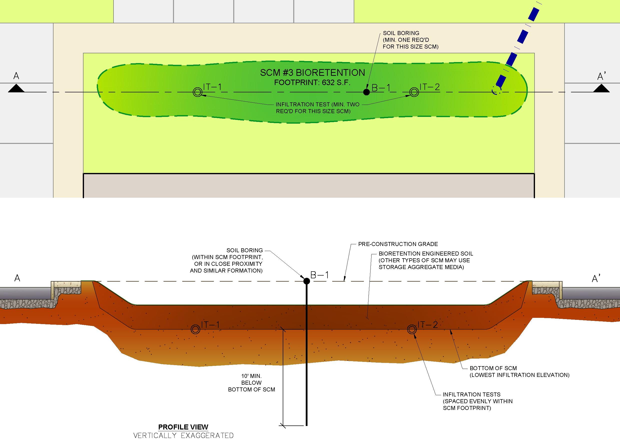
The remainder of this page is intentionally left blank.
Figure F.1 Example of Appropriate Spacing and Depth for Soil Infiltration Tests