Pushing the Canada


Pushing the Canada
A publication of the Ontario Building Envelope Council
Pushing the Envelope Canada
A publication of the Ontario Building Envelope Council Fall 2024
Published For:
The Ontario Building Envelope Council
2800 – 14th Ave.
Suite 210
Markham, ON L3R 0E4
Phone: 647-317-5754
Fax: 416-491-1670
info@obec.on.ca
www.obec.on.ca
©2024 Matrix Group Publishing Inc. All rights reserved. Contents may not be reproduced by any means, in whole or in part, without the prior written permission of the publisher. The opinions expressed in this publication are not necessarily those of Matrix Group Publishing Inc. Printed in Canada.
OBEC does not specifically endorse the editorial, products or services contained within this magazine. These products and services are presented here as an indication of the various possibilities in the Marketplace. OBEC wishes to advise the reader that sound Building Science Practices should be applied to any and all product or service selections. OBEC does not make or imply any warranties as to the suitability of any of these products or services for any specific situation. Furthermore, the opinions expressed in this magazine’s editorial content may not necessarily reflect the opinions of OBEC.


Pushing the Envelope Canada
A publication of the Ontario Building Envelope Council
Fall 2024
Published By:
Matrix Group Publishing Inc.
Return all undeliverable addresses to:
309 Youville Street
Winnipeg, MB R2H 2S9
Toll Free: 1-866-999-1299
Toll Free Fax: 1-866-244-2544 www.matrixgroupinc.net
Publications Agreement Number: 40609661
President & CEO
Jack Andress
Operations Manager
Shoshana Weinberg sweinberg@matrixgroupinc.net
Senior Publisher
Jessica Potter
Publishers
Julie Welsh, Christine Scarisbrick
Editor-in-Chief
Shannon Savory ssavory@matrixgroupinc.net
Editor / Social Media Manager
Jenna Collignon
Finance /Administration
Lloyd Weinberg, Nathan Redekop accounting@matrixgroupinc.net
Director of Circulation & Distribution
Lloyd Weinberg distribution@matrixgroupinc.net
Sales Manager
Jeff Cash jcash@matrixgroupinc.net
Sales Team Leader
Colleen Bell
Matrix Group Publishing Inc. Account Executives
Colleen Bell, Jackie Casburn, Rob Gibson, Jim Hamilton, Scott Hendren, Frank Kenyeres, Sandra Kirby, Charlie Langsford, Andrew Lee, Brian MacIntyre, Lynn Murphy, Caitlin Nakamura, Wilma Gray-Rose, Joseph Ukaoha
Layout & Design
Travis Bevan
Advertising Design
James Robinson
©2024 Matrix Group Publishing Inc. All rights reserved. Contents may not be reproduced by any means, in whole or in part, without the prior written permission of the publisher. The opinions expressed in this publication are not necessarily those of Matrix Group Publishing Inc. Printed in Canada.
OBEC does not specifically endorse the editorial, products or services contained within this magazine. These products and services are presented here as an indication of the various possibilities in the Marketplace. OBEC wishes to advise the reader that sound Building Science Practices should be applied to any and all product or service selections. OBEC does not make or imply any warranties as to the suitability of any of these products or services for any specific situation. Furthermore, the opinions expressed in this magazine’s editorial content may not necessarily reflect the opinions of OBEC.
MEET OUR EXPERTS
ROB HADDOCK
Rob Haddock is a former contractor, awardwinning roof forensics expert, author, speaker, building scientist and the founder of S-5!
He is the inventor of the non-invasive clamps for fastening accessories to standing seam metal roofs and the originator of an all-new and distinctive product category: engineered, manufactured metal roof attachment solutions. His personal goal is to promote metal roofing as the most desired, accepted, user-friendly, most coveted roof in the construction industry globally.
To learn more, visit www.S-5.com.
NATHAN MORLOCK
Nathan Morlock, founder of Engineered Architecturals Ltd., and the inventor of the Turtle Rib brand with five patents pending brings a unique background as a union-trained sheet metal worker. Morlock later became a partner in a specialty architectural products company.
DAVID DE ROSE, M.A.SC., P.ENG., BSS
David De Rose, M.A.Sc., P.Eng., BSS is a Principal for Synergy Partners. He is the Chair of the CSA A440.6 subcommittee that deals with high-exposure Fenestration Installation and is a voting member for CSA-S478 Standard of Building Durability. David is currently a part-time Professor at Toronto Metropolitan University and the University of Toronto.
ANTHONY LUKES, B.ENG.
Anthony Lukes, B.Eng., is a Project Manager for Synergy Partners. Anthony has worked on over 200 projects over a nine-year career in building Science and Restoration. He specializes in building enclosures and has extensive experience in the evaluation and field testing of building façades.
GREG HILDEBRAND, M.SC.ENG., CET
Greg Hildebrandt, M.Sc.Eng., CET, was the head of the façade engineering group at EXP Services and a leading expert in the Canadian window and door industry.
ANTON VAN DYK, M.ENG., P.ENG.
Anton Van Dyk has over 25 years of building envelope related consulting and construction experience. As Building Codes have evolved at a rate faster than ever, Anton's current focus is assisting fenestration manufactures, specifiers, and installers understand the paths of code compliance in British Columbia and throughout North America.

JONATHAN SMEGAL
Based in Waterloo, Ontario, for nearly 20 years, Jonathan Smegal is an associate and senior building science consultant at RDH. He leads projects related to laboratory research, forensic analysis of building failures, litigation, hygrothermal modeling, and field monitoring of building enclosure performance. As a researcher, he is an author on multiple peer-reviewed papers and has frequently shared his work through industry publications, webinars, and speaking events.


ADAM HOSNY, M.ENG., P.ENG.
Adam Hosny, M.Eng., P.Eng., is a Structural Engineer & Partner at Capacity Engineering Limited. His practice focuses on Structural Engineering with a special interest in Building Envelope design, failure diagnosis, and testing. In his role at Capacity Engineering, he is responsible for structural and building envelope forensic investigation, structural design, and is the lead engineer on Tarion RB 19R reviews.

DENNIS ANDERSON
Dennis Anderson was a Project Manager with the NFRC and resigned to join Underwriters Laboratories in Chicago to build and certify a thermal hot-box chamber before rejoining NFRC and is currently the Senior Programs Manager engaged primarily with auditing NFRC-accredited laboratories and international computer simulation training.
NENSI BABOCI, B.A.SC., M.ENG., P.ENG.

Nensi Baboci, B.A.Sc., M.Eng., P.Eng., is a Project Engineer at RJC Engineers' Building Science Group. Her area of expertise includes assessment, investigation and remediation of building envelope systems, and implementation and management of retrofit projects.
BRANDON GEMME, P.ENG., BSS, CPHD


Brandon Gemme, P.Eng., BSS, CPHD, is a Project Manager at Leading Edge Building Engineers. He has been involved in several deep energy retrofit projects and has gained valuable experience in the design, modelling, and management of them.
ARIEL ZHU
Ariel is a recent graduate from Toronto Metropolitan University with a Master of Applied Science in Building Science. Her thesis study focused on the risk reduction design of the storm-water detention assembly to mitigate urban flooding. Ariel now marries her experience in design with sustainability and retrofit as a Project Coordinator.


Daniel Aleksov Principal & Co-Founder Leading Edge Building Engineers
AMessage from the President
The Future Direction of OBEC
s we approach the fall of 2024, it is important to reflect on the amazing year that has passed for our members of the Ontario Building Envelope Council (OBEC). I am grateful to be the president in a time where many new initiatives are unfolding thanks to the countless efforts of our board and committee members, authors, speakers, sponsors, and members at large. It is also important to thank our past board members and volunteers who have helped elevate OBEC to where it is now. This association has been built by individuals who have the passion and dedication to pass on expert knowledge of building science and leave a legacy behind to the next generation of professionals in the industry.
Our continued efforts to partner with like minded organizations is helping spread awareness of our association while simultaneously providing more education, social, and business opportunities to our members. First, our inaugural golf tournament with the Canadian Condominium Institute (CCI) Golden Horseshoe chapter was a tremendous success and we appreciate everyone who participated and sponsored this event. The overwhelming positive feedback is encouraging to make this a regular summer social event moving forward.
In terms of upcoming continuing education, the joint OBEC/ IIBEC BES Conference is fast approaching and packed with high calibre presentations and speakers from across North America. You will also have access to a vast number of industry exhibitors that can help you understand the latest trends and technologies available at your disposal in the building envelope market. Do not miss the opportunity to benefit from this event as well as participate in the OBEC annual
general meeting (AGM) which will be held on the second day on October 1, 2024.
Your continuous feedback and suggestions from ongoing surveys and polls have helped us with planning and executing on events and initiatives that are aligned with OBEC’s strategic short-term goals. We would like to reassure our members that their input is always valued and taken into consideration as we plan for every upcoming year. Please continue to share your unique perspectives and insights as OBEC approaches four decades as an association.
We are thrilled that post-secondary students continue to become OBEC members and host their own student chapter events as well as attend OBEC organized events. Many thanks to our corporate sponsors that have facilitated and supported this initiative for the past few years. This year the Anthony A. Woods (The Beckie) award will be granted to recognize an individual, nominated by their peers, who has made a significant contribution to the design, construction and performance of the building envelope. The winner of the award will be announced at the upcoming AGM.
In closing, I am incredibly enthusiastic and optimistic about the future direction of OBEC and the major initiatives that we are collectively working on. There is a lot of hard work and challenges to overcome, but we are determined to reach our lofty goals. Thank you for your continued support, dedication, and commitment to excellence. I look forward to working closely with each of you as we navigate this exciting journey together. If you are interested in volunteering on one of our many active committees, please reach out to us via email at info@obec.on.ca. n
BOARD OF DIRECTORS
President: Daniel Aleksov, P.Eng., BSS, Leading Edge Building Engineers Inc.
Vice-President: Negar Pakzadian, B.Eng., M.Arch., MBSC., BSS, CPHD, Major Capital Project Manager
Treasurer: Matthew Gelowitz, M.A.Sc., CPHC, LEED® AP, Synergy Partners Consulting Ltd.
Operations Manager: Sherry Denesha, Ontario Building Envelope Council (OBEC)
Directors:
Mohammed Dawoud, P.Eng, M.Eng, BSS, CPHD, NFRC Certified Simulator, Ennova Facades
Brandon Gemme, P.Eng., BSS, CPHD, Leading Edge Building Engineers Inc.
Andrea Mucciarone, BA, MBSc., BSS, RJC Engineers
Antoine Possik, Northern Caulking Inc.
Robert Quattrociocchi, BSS, Synergy Partners
Shohreh Salimpour, M.Eng., P.Eng., M.Arch., OAA (Int.), LEED® AP, PMP, OHE Consultants
Kelsey Saunders, KPMB Architects


UPCOMING BUILDING SCIENCE SPECIALIST EXAMS AND EVENTS
OBEC is currently working with the other BECs across Canada to offer the Building Science Specialist (BSS) designation. The BSSB will promote the Building Science Specialist designation across the country, leading to greater prestige for holders of the BSSO, and giving the designation increased authority. As part of this process, we’re doing away with the Professional Member category; you will become an individual member holding the Building Science Specialist designation.
BES+ 2024 IIBEC/OBEC BES
DATE
September 29 to October 1, 2024
LOCATION
Toronto, Ontario
REGISTER TODAY HERE: HTTPS://BSSB.CA/BSS-EXAM/BSS-EXAM-APPLICATION-2.

MATERIALS EXAM & MECHANICAL SYSTEMS EXAM
DATE
Friday, October 18, 2024
TIME
1:00 P.M. – 5:00 P.M. EST
LOCATIONS
• BSSB Office, 2800 14th Avenue., Suite 210, Markham, ON (1:00 pm – 5:00 pm ET).
• Kitchener-Waterloo area – TBD (1:00 pm – 5:00 pm ET).
• Ottawa area – TBD (1:00 pm – 5:00 pm ET).
• Edmonton, AB – TBD (9:00 am – 1:00 pm MT).

To Retain or Not to Retain: Snow on Your Metal Roof?
By Rob Haddock, S-5! & Nathan Morlock, Engineered Architecturals Ltd.
The debate surrounding snow retention is a prevalent topic among Canadian designers and contractors. One perspective cautions against retaining snow on roofs due to concerns over compromising the building’s structural integrity. There is also apprehension that accumulated snow could exceed the roof’s design load capacity, potentially leading to failure. The other perspective advocates for mechanical snow retention to manage snow evacuation in a controlled manner to prevent hazardous rooftop avalanches and minimize safety risks to pedestrians and property. What is the “safe” middle ground?
Understanding the implications of each perspective is crucial not only to ensure the safety and longevity of the roof but also for overall public safety.
The Canadian National Building Code (NBC) supports using snow retention only
when necessary and encourages planning for natural snow shedding to avoid excessive accumulation.1 However, the terms “if required” and “natural shedding” are vague. Does “natural shedding” become a safety issue when a rooftop avalanche crushes a vehicle, or only after fatalities occur? Additionally, what happens if ice dams form on eave overhangs, blocking “natural” snow shedding?
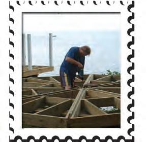
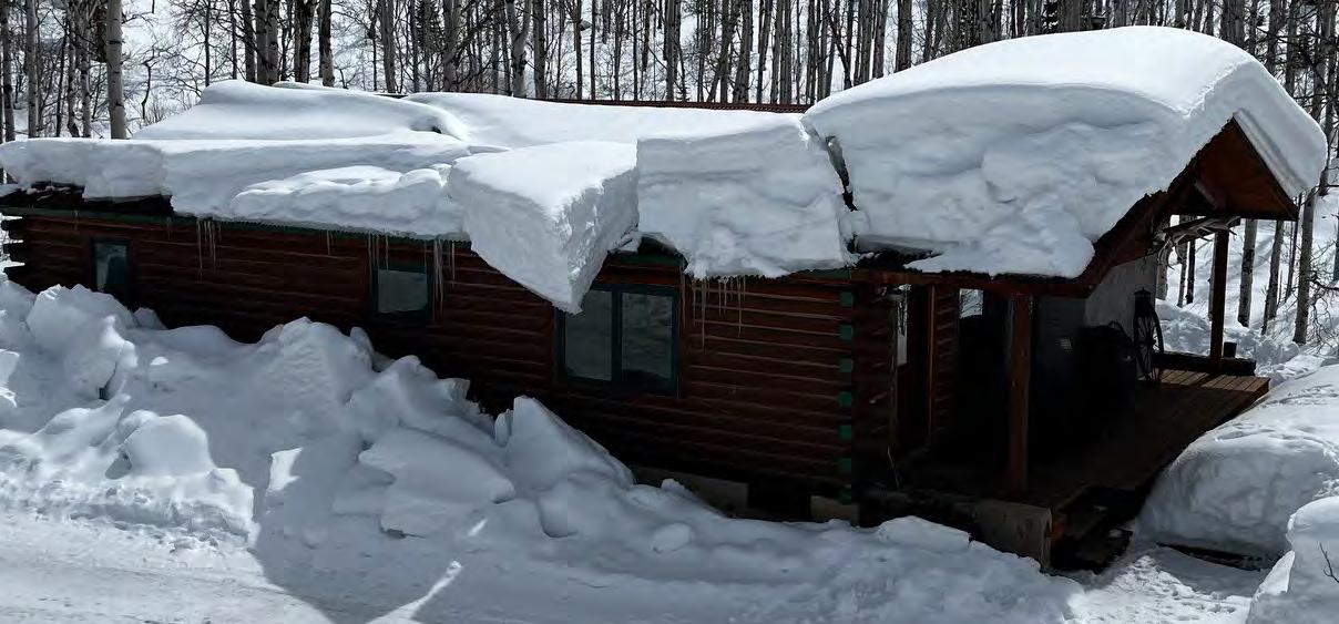
The Roofing Contractor’s Association of British Columbia (RCABC) defines high snow load areas as those with snow loads over 3.5 kPa (73.10 psf) and recommends designing roofs with a significant slope to facilitate snow shedding.2 Congruent with NBC, the use of snow retention systems is advised only where public hazards exist, e.g., pedestrian areas or building entrances.2 What about utility workers checking a meter or children having a snowball fight in the backyard? “Natural” snow shedding.
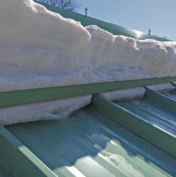
“Natural” snow shedding. Photos courtesy of S-5!
The RCABC also states that allowing snow to discharge freely from roofs is preferable to avoid roof system damage,2 though more damage is often seen from “free discharge” than retention.
Canada has not seen significant structural failures from snow accumulation on buildings built to code.3 The NBC states that light frame buildings, as defined in Part 9, have not collapsed under these loads. Part 9 covers basic home and small building requirements, while Part 4 covers more complex structures with stringent safety standards.3 The NBC 2020 emphasizes that structural design requirements are defined by local legislation.3
Modern Canadian buildings are designed to withstand loads based on climatic criteria from the federal department, Environment Canada, which are based on 1-in-50-year event data.4 For small light frame buildings, Part 9 uses simplified calculations involving snow load (Ss), reduction factor (Cb), and rain surcharge (Sr). More complex buildings follow Part 4, considering factors like building type, adjacent structures and snow drift.4
In high snow load or remote areas without local climate data, municipalities contract with Environment Canada for specific climatic data for a small fee. A registered professional ensures the design meets building codes and withstands anticipated loads.4
Whether Part 4 or Part 9, the trick is to get the design vertical roof snow load credibly correct – a difficult proposition considering the objective language of code. Then, given the irregular patterns of extreme weather events globally, prudence is required to reduce future risks in light of code or climate changes. If higher minimum safety factors were mandated by codes, it would ease the burden on designers.
Typical verbiage on term sheets from snow retention suppliers may read: “Our design and quote are based on the ‘known’ snow load. It’s the customer’s obligation to monitor the rooftop snow load and remove or reduce excessive snow loads to avoid system failure. We recommend a licensed engineer review the layout as designed to avoid potential system failure.” (So, the buck is passed again.)
But practically speaking, how will the “customer” monitor actual snow loads, and is it a safe practice to reduce excessive snow loads during or following a blizzard?
Every year there are reports of rooftop avalanches causing extensive property damage and personal injury. Often this is due to
attempts to remove snow from a roof. Recommending an engineer review the layout to avoid system failure does not eliminate the hazard – it just shifts blame to the engineer.
The metal roof experts at S-5! emphasize the primary function of snow guards is to prevent snow from sliding off the roof in an uncontrolled manner. A rooftop avalanche endangers people and property whether anticipated – or not. A properly designed snow retention system will allow snow to manageably evacuate (by thaw and sublimation). It’s the uncontrolled and unexpected rooftop avalanche that causes damage and life/safety issues.
A common misconception is that snow guards can lead to an “excess” accumulation of snow, exceeding the design load capacity prescribed by the building code. For this to happen, an event would need to surpass the 1-in-50-year data including the designer’s safety factor.
The NBC and its Structural Commentaries include provisions for reducing roof snow loads based on factors such as roof slope and slipperiness. However, the code also provides cautionary guidance regarding
these reductions, stressing the importance of carefully evaluating actual conditions and associated risks.
For instance, if the structure was initially designed to shed snow and reductions in snow loads (according to incumbent code) were implemented and subsequently a snow guard system was added, the scenario could increase the risk of structural failure earlier than the failure of the snow retention system.
More frequent failures stem from under-designed snow guard systems that fail to account for three basic design factors adequately. While engaging a professional engineer to assess site-specific climatic data according to code is essential, it is also crucial to recognize the three variables frequently ignored: design roof snow load, roof angle and roof (rafter) length.
Having conducted 5,000 plus load tests on every conceivable metal roof profile, S-5! recommends the installation of a certifiably tested snow retention system and engineered to these three site-specific variables using an appropriate factor of safety. (The S-5! system calculator defaults to 2.0 but enables the user to modify.)
S-5! ColorGard allows snow to manageably evacuate by thaw and sublimation.
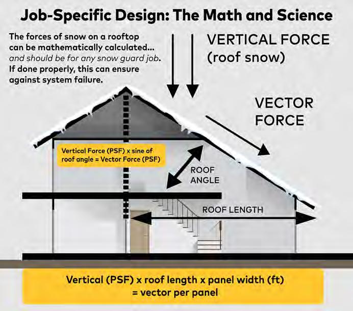
UNDERSTANDING THE PRECISE MATH AND SCIENCE
Properly calculating the required population and spacing of snow guards is critical for any project. If it is inadequate, the system will fail at below-design snow loads – if overly adequate, there is a risk of overspending. Appropriate design is determined by science and math, not guesswork.
The correct population is found by calculating the tributary service loads to be resisted and matching them to the tested, allowable load resistance of the specific snow retention system proposed for the project.
DETERMINE THE VECTOR FORCE
The force applied to a snow guard system is a simple calculation but varies widely with:
• The design roof snow load;
• Roof slope; and
• (Rafter) length from eave to ridge.
Further, the buyer should demand evidence of three quality assurances for a reliable system design from the snow guard vendor:
1. Certified testing specific to the roof being used on the project;
2. Certified manufacturing; and
3. Proof of engineered calculations.
KEY TAKEAWAY
S-5! advocates for a rigorous approach to snow retention system design, emphasizing the importance of a certifiably tested and engineered snow retention system based on precise load calculations. Their snow calculator tool assists designers and engineers in determining the optimal configuration of snow guards for your
metal roof project. For more information, visit www.s-5.com. n
Rob Haddock, director of the Metal Roof Advisory Group and CEO and founder of S-5!, is a former contractor, award-winning roof forensics expert, author, lecturer and building envelope scientist who has worked in various aspects of metal roofing for five decades.
Nathan Morlock, founder of Engineered Architecturals Ltd., and the inventor of the

Turtle Rib brand with five patents pending brings a unique background as a uniontrained sheet metal worker. Morlock later became a partner in a specialty architectural products company. He has garnered international expertise evaluating building product manufacturers and offers extensively tested technical products with a focus on supporting installations to ensure project success. Engineered Architecturals proudly offers S-5!
REFERENCES:
1. Canadian National Building Code (NBC), Structural Commentaries (User’s Guide – NBC 2015), Commentary G. https://nrc.canada.ca/en/ certifications-evaluations-standards/ codes-canada/codes-canada-publications/structural-commentaries-usersguide-nbc-2015-part-4-division-b.
2. Roofing Contractor’s Association of British Columbia (RCABC), Roof Practices Manual (RPM), Section 1.1.3.2 Snow Loads. https://www. rcabc.org/technical/roofing-practices-manual-rpm/.
3. NBC 2020 & BCBC 2024, Parts 9 and 4.
4. Environment Canada, Climatic Design Criteria.
Calculating vector force and vertical force snow loads on metal roofing.
The S-5! approach calls for thorough testing and consistency.

Compressed Air Frost Spray (CAFS) Testing
By David De Rose & Anthony Lukes, Synergy Partners & Greg Hildebrand, EXP Services
A Cost-Effective Method to Screen Insulating Glazing Unit Quality and Durability
Insulating Glazing Units (IGUs) have long been a staple in new construction and building renewal projects. Predicting IGU failures is a challenge for building owners, contractors, and consultants alike, with fogging often only becoming apparent after IGU seals have already failed. Improving IGU performance and extending their service life are necessities for resilient and sustainable construction. This article explores a simple in-field or in-plant test method for screening IGUs descriptively named the Compressed Air Frost Spray (CAFS) test. The CAFS test allows testers to screen many IGUs in a short period of time in a cost-effective manner.
IGUs are typically composed of two (or more) glass panes separated by a spacer with desiccants. The units are held together with a combination of sealants that make up the primary and secondary seals and the gas space between the glass panes is filled with air or inert gases such as argon to improve thermal and acoustic performance.
There are several potential issues with IGU fabrication that may lead to premature failure. These issues may be related to deficiencies during the manufacturing process. IGU fabrication techniques could be altered to address deficiencies and improve
performance/durability where IGU issues are detected early in the fabrication process.
IGU failure becomes apparent when condensation or fog appears between the glass panes. At the point that condensation or fog appears between the glass panes, the seals will likely have already been compromised for some time. The insulating properties of the unit may be reduced before visual signs of fogging or condensation between panes becomes evident. Early failure detection can help maintain energy efficiency and help owners budget/plan for future replacement.
Refined dewpoint testing of IGUs such as described in ASTM E576 utilizes specialized equipment to determine temperatures at which fogging occurs (within +/- 5 °C). Refined dewpoint testing of IGUs, while reliable, is costly and is not always feasible for rapid, in-plant or in-field assessments of many units in a short time frame.
The CAFS test method was developed by the late Greg Hildebrand. Greg co-chaired the CSA A440 Series Technical Committee that sets fenestration standards. He also served as the Canadian Chair of NAFS (North American Fenestration Standard) as well as working on many committees/task groups with the ASTM (American Society of Testing Materials).
The CAFS test is a simple, quick and cost-effective method for screening many IGUs in a short time frame. The results of the CAFS test help to identify potential IGU issues prior to visual deterioration. The test can be used early in a project to diagnose potential fabrication issues that may otherwise lead to internal fogging or to assist with service life planning in existing buildings.
The following materials are required to complete the test:
• 10 oz cannisters of compressed air. The number of cannisters of compressed air is dependent on the number of IGUs to be tested. In our experience, one cannister of compressed air can test 4-6 IGUs;
• A T-type thermal couple connected to a data-logger device; and
• An ice scraper and cloth.
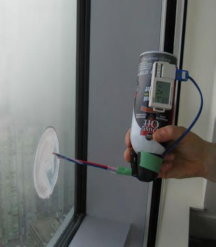
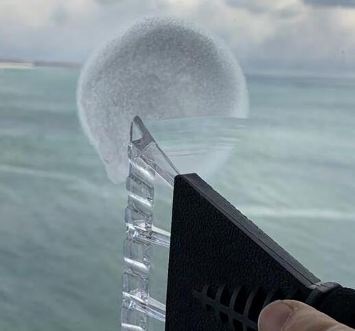
The objective of the test is to apply a temperature of ~-50 °C to a small area on the surface of the IGU. This is achieved by applying the liquid from an inverted compressed air cannister to the surface of the IGU. The thermocouple and data logger are used to record the temperature of the liquid from the compressed air cannister.
The procedure for completing the test on a double glazed IGU is as follows:
Applying compressed air fluid to an IGU. A thermocouple connected to a data logger is attached to the nozzle of the compressed air cannister to measure fluid output temperature. Photos and graphics courtesy of Anthony Lukes.
• Connect a thermocouple to the nozzle of the compressed air canister to check output temperature;
• Hold the compressed air cannister upside down, approximately 25 mm away from the IGU;
• Apply compressed air to the IGU in four slow, circular revolutions (approximately 100 mm in diameter) with each revolution lasting about one second. This constitutes one cycle. This can be done on either side of the IGU (Surface 1 or 4). Gloves should be worn to mitigate liquid from contacting the testers skin which may otherwise cause burns;
• Allow time for the compressed air to evaporate after each cycle. Test adjacent IGUs simultaneously during this period, typically grouping four IGUs together. Apply the four circular revolutions to the other three IGUs sequentially;
• Once all four IGUs have completed the first cycle, enough time will have passed for frost to develop on the first IGU;
• Repeat the procedure for four cycles (16 total revolutions per IGU); and
• After completing all cycles, use a frost scraper and cloth to remove the frost from the IGU surface.
A failed IGU is identified by the presence of fog or condensation between the glass panes (i.e., surfaces two and/or three). For triple-glazed IGUs, both the interior and exterior surfaces must be tested to check for moisture within either gas space.
This test can determine if the dewpoint of an IGU is below -50 °C which would indicate that there are no imminent signs of IGU failure. A failure during this test i.e. the presence of moisture in the cavity at -50 °C, suggests a potential issue or a reduced expected service life for the IGU. If fogging or condensation are detected in the IGUs during screening, more refined dewpoint testing with more specialized equipment can be completed to refine the dewpoint temperature between glass lites to within +/- 5 °C.
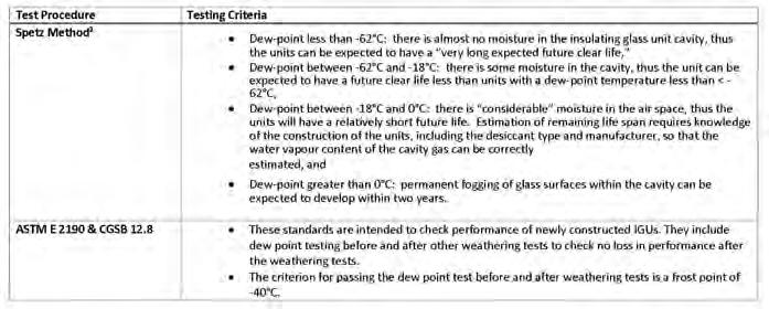
In the 1980s, the Sealed Insulating Glass Manufacturers Association (SIGMA) began a study to track the performance of 2,400 IGUs installed in various buildings and cities in the USA. Jim Spetz, their consultant who carried out field dewpoint testing developed a qualitative method of determining the relationship between IGU dewpoint temperatures to likelihood of fogging (see Figure 2). Dewpoint temperatures of IGU can also be tracked in subsequent readings from
year-to-year to track tends to more accurately extrapolate time to fogging.1
CAFS testing has been utilized to screen IGUs in both new construction projects and on existing buildings.
At a new construction project for an Institutional project, CAFS testing was utilized to screen recently installed large triple-glazed IGUs. No failures were observed, and the results provided confidence to the Consultant and Owner that there are no manufacturing issues with the new IGUs that could lead to premature failures.
CAFS testing has also been utilized on various existing buildings to screen existing IGUs. At one large residential building in Toronto, CAFS testing revealed failures in all the units that were tested despite no visible signs of fogging prior to testing. Existing IGUs were approximately 40 years of age at the time of testing. This testing was used to help owners plan for IGU or window replacement.
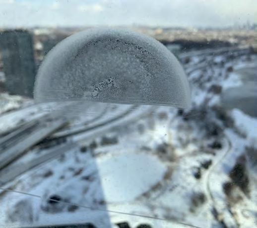
A frost scraper is used to remove frost from the IGU following the test.
A successful test is identified when no fog, condensation, or frost is observed between the glass panes.
Figure 2: The Spetz Method for qualitatively determining time-to-fogging.
At another large residential building in Toronto, CAFS testing was completed on over 45 IGUs in a few hours. Existing IGUs were approximately 30 years of age at the time of testing. No failures or imminent signs of failure were observed during the testing. The results of the tests helped the owners defer IGU replacement in their Reserve Fund Study.
The CAFS test offers significant benefits in screening both new and existing IGUs. It’s simplicity, cost-effectiveness and rapid results make it an invaluable tool for detecting potential IGU issues. Building owners, IGU manufacturers, and consultants can effectively assess IGU quality or make more
informed decisions with respect to IGU replacement planning. n
David De Rose, M.A.Sc., P.Eng., BSS is a Principal for Synergy Partners. He is the Chair of the CSA A440.6 subcommittee that deals with high-exposure Fenestration Installation and is a voting member for CSA-S478 Standard of Building Durability. David is currently a part-time Professor at Toronto Metropolitan University and at the University of Toronto.
Anthony Lukes, B.Eng., is a Project Manager for Synergy Partners. Anthony has worked on over 200 projects over a nine-year career in building Science and Restoration. He specializes in building enclosures and has extensive
experience ein the evaluation and field testing of building façades.
Greg Hildebrand, M.Sc.Eng., CET, was the head of the façade engineering group at EXP Services and a leading expert in the Canadian window and door industry. Greg chaired or sat on committees for CSA A440, North American Fenestration Standard (NAFS), and the American Society for Testing and Materials (ASTM) during his career.
REFERENCE:
1. G.R. Torok. Predicting Time-to-Fogging of Insulating Glass Units. 11th Canadian Conference on Building Science and Technology. Banf, Alberta, 2007.

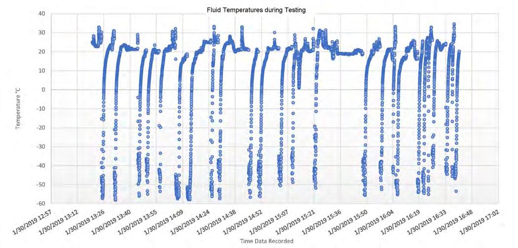
Figure 1: A sample of data from the data logger tracking fluid temperature per test.
Kestrel Court: Case Study of a Successful Deep Energy Retrofit
By Jonathan Smegal, RDH Building Science

Two-thirds of the buildings that exist today will still exist in 2040,1 which means many buildings will require a deep energy retrofit to meet CO2 reduction goals in Canada, the United States, and the rest of the world.
This case study considers Kestrel Court: a cold-climate, net-zero energy ready (NZER) project located in London, Ontario. A NZER building can, with the addition of solar panels or other on-site renewable energy technologies, achieve net-zero energy performance annually. The results of this case study provide insight into deep energy retrofit strategies that could
contribute to meeting national and global energy targets. A report (linked at the end of this article) provides additional details, including the mechanical systems strategies used for this project.
The Kestrel Court project received inspiration from the Local Energy Efficiency Partnerships (LEEP) program and received funding through the Office of Energy Research and Development (OERD) at Natural Resources Canada (NRCan).
PROJECT BACKGROUND
The Kestrel Court student townhomes at Fanshawe College were constructed in
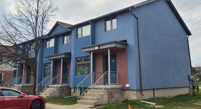
1993 and represent construction practices of their era (see Figure 1).
Fanshawe College proposed deep energy retrofits of 11 units (three townhouse buildings) using five different exterior insulation systems and six HVAC packages to achieve NZER levels. This project was completed by Fanshawe College in the fall of 2023. Significant industry in-kind support was provided for the enclosures, windows, and HVAC equipment by several manufacturers who participated in the LEEP for Renovations initiative in London in 2017-2018.
Key objectives of the Kestrel Court project included the following:
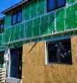
Figure 1: Kestrel Court pre-retrofit student townhomes constructed in 1993. Photos courtesy of Jonathan Smegal.

• Achieve net-zero energy ready measured performance annually on the three townhome blocks working with five different insulation manufacturers;
• Reduce greenhouse gas emissions as much as possible; and
• Provide technology transfer to the industry so others may also benefit from the learning acquired on the project.
BUILDING IMPROVEMENTS
In a deep energy retrofit, it is critical to create a highly insulated, airtight enclosure. Enclosure improvements are intended to control the heat loss/heat gain between the interior and exterior to reduce the energy required for space conditioning.
The Kestrel Court townhome enclosures were retrofit using a combination of exterior insulation strategies, an exterior air barrier system, and all new, high-performance windows and doors.
ABOVE-GRADE WALL RETROFIT STRATEGIES
Five insulation manufacturers and five specific approaches were used for the abovegrade wall assembly energy retrofits. Modelling conducted for the study determined that the insulation levels should be R-60 in the attic, R-28 (effective) in the above-grade walls, and R-20 for the full-height basement insulation. The following sections will describe the five approaches taken and the insulation manufacturers who participated in the project.
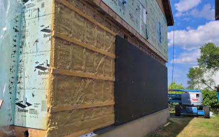
1. BASF wall system
Following the removal of cladding and insulating sheathing, horizontal 2x3 strapping was installed on the exterior of the 2x4 framing and closed-cell spray polyurethane foam (ccSPF) was installed five inches (127 mm) in depth from the interior drywall to the 2x3 strapping. Two inches (50 mm) of Neopor® EPS was installed against the
horizontal strapping and covered with a water-resistant barrier (WRB), 1x4 vertical strapping, and cladding (see Figure 2).
2. Dryvit wall system
The Dryvit Outsulation® MD assembly was the only retrofit strategy that did not require the removal of the existing masonry on the first storey. Exterior gypsum was installed over the framing in locations where the vinyl cladding had been removed. A manufacturer formulated fluid-applied air/ water barrier was installed over the masonry and exterior gypsum and made continuous with all adjoining assemblies and penetrations. EPS foam 3.5 inches (89 mm) thick was installed over the air/water barrier, and an EIFS finish coat with varying impact protection based on height was installed over the surface of the EIFS (see Figure 3).
3. Owens Corning wall system
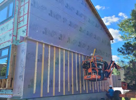
The Owens Corning assembly is a system of exterior XPS CodeBord® insulation and sill gasket membranes for air control installed directly to the exterior face of the framing without sheathing. Two layers of two inch (50 mm) XPS were installed with the interior layer taped and sealed. On the exterior of the XPS insulation, 1x4 strapping was installed through the exterior insulation for cladding attachment (see Figure 4).
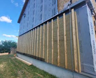
4. Plasti-fab Insulspan® wall system
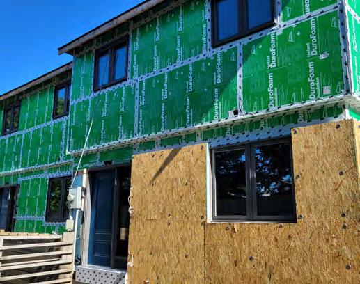
The Plasti-fab Insulspan® wall system included an initial layer of one inch (25 mm) poly-faced EPS DuroFoam with all joints taped and installed directly against the framing as the primary air control layer of the system. A nailbase panel with 3.5 inches (89 mm) of EPS foam bonded to an exterior OSB facer was secured to the structure. A WRB was installed over the OSB for rainwater protection and 1x4 strapping was installed to provide a drained and vented cavity for cladding attachment (see Figure 5).
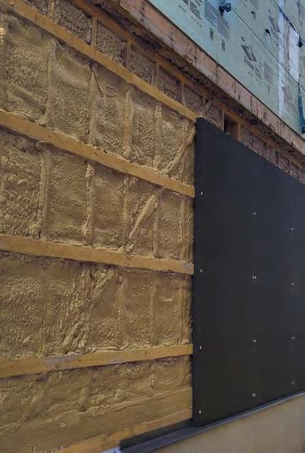
5. ROCKWOOL wall system
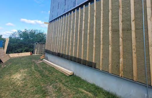
The ROCKWOOL wall system included the removal of the existing insulating sheathing and installation of new OSB sheathing installed over the framing. A Dorken self-adhered WRB was installed over the OSB sheathing. ROCKWOOL ComfortBoard 110 was installed in a four inch (102 mm) layer, with exterior vertical 1x4 strapping installed on the exterior of the insulation to provide a drained and vented cavity, and cladding installed to the vertical strapping (see Figure 6).
Figure 3: Dryvit wall system with finished EIFS deep energy retrofit enclosure.
Figure 2: BASF first-floor insulation in progress (second floor is original).
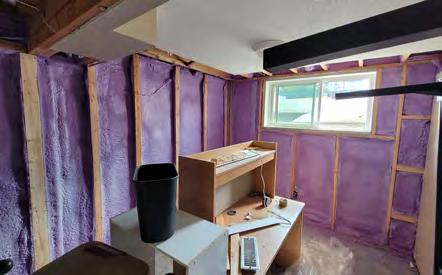
BELOW-GRADE ENCLOSURE
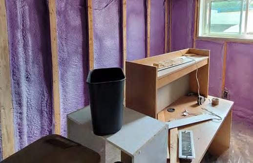
For the project’s below-grade retrofit strategy, 2 pcf ccSPF was installed against the interior of the concrete foundation wall as air, vapour, and thermal control. The ccSPF was continuous behind the basement framing against the concrete, and in the rim joist. The basements in every unit were constructed in the same way (see Figure 7).
ENCLOSURE AIRTIGHTNESS AND MONITORING
All the units were airtightness tested prior to renovations and again following construction. After the renovations, all units met and exceeded the CHBA required airtightness criteria for the Net-Zero Energy Ready labeling program of 1.5 ACH at 50 pascals.
Moisture levels in the enclosures are being monitored using relative humidity, and
wood moisture content sensors placed at various locations within the enclosure system. After the installation of an effective air control layer and exterior continuous insulation, each wall system’s risk of moisture condensation and accumulation was reduced. Preliminary data analysis following the first winter indicates that the wall assemblies have no elevated moisture levels or risk of moisture accumulation.

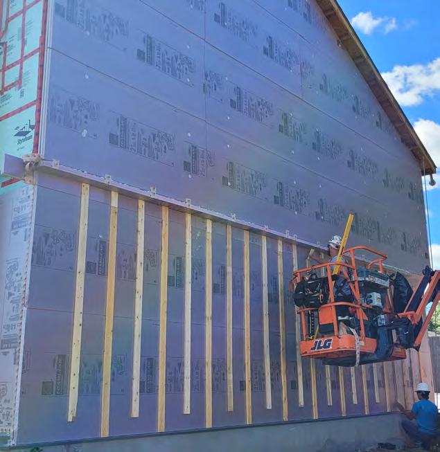
Figure 5: Plasti-fab Insulspan® wall assembly during installation.
Figure 4: Owens Corning exterior insulation being installed with strapping.

SUMMARY
A NZER retrofit to three townhouses at Fanshawe College’s Kestrel Court was implemented to reduce energy consumption and reduce greenhouse gas emissions. The project’s high energy performance was achieved using four key strategies: exterior continuous insulation, improved airtightness, higher performance windows and doors, and upgraded mechanical systems.
NRCan will continue to share the valuable information gained during this project related to all aspects of design, and the measured performance of the enclosure and HVAC equipment, through further case studies and articles such as this one.
The author’s recorded presentation and full report of the case study can be accessed here: https://www.rdh.com/resource/netzero-ready-deep-energy-retrofits-kestrelcourt-case-study/. n
Based in Waterloo, Ontario, for nearly 20 years, Jonathan Smegal is an associate and senior building science consultant at RDH. He leads projects related to laboratory research, forensic analysis of building failures, litigation, hygrothermal modeling, and field monitoring of building enclosure performance. As a researcher, he is an author on multiple peer-reviewed papers and has frequently shared his work through industry publications, webinars, and speaking events.
REFERENCE:
1. International Energy Agency (IEA), “Technology and Innovation Pathways for Zero-carbon-ready Buildings by 2030: Introduction,” https://www. iea.org/reports/technology-and-innovation-pathways-for-zero-carbon-ready-buildings-by-2030/introduction. Accessed December 7, 2023.
Figure 8: Spray foam installed against the interior of the foundation wall.
Figure 6: ROCKWOOL deep energy retrofit wall assembly.
From Roof Collapse to Remediation: Understanding RAAC in Ontario’s Buildings
By Brandon Gemme, Leading Edge Building Engineers, Ltd
The use of Reinforced Autoclaved Aerated Concrete (RAAC) has been a contentious topic in Ontario. In November 2023, the Ministry of Education issued a memorandum to the Directors of Education requesting all school boards “implement an investigation, assessment, and management strategy for RAAC within their buildings”1 in response to the 2018 partial collapse of a UK school roof constructed with RAAC panels, prompting the closure of 104 similar schools. More recently, the Ministry of Infrastructure announced that it would be closing the Ontario Science Centre as of June 2024, with one of the major justifications for the closure being the condition of the RAAC roof panels.2 Some have criticized the decision to close the Ontario landmark, pointing out that the engineering report prepared by Rimkus identifies only one RAAC roof panel as being in critical condition and an additional six per cent as high risk.3 Regardless of your opinion on the closure, RAAC is an important topic that merits further discussion and awareness.
To assist building owners and restoration professionals working with RAAC, this article will provide a brief history of RAAC construction in Ontario, including commonly used products, describe the primary durability concerns associated with RAAC, explain how to identify RAAC structures in existing buildings, and provide some recommendations on the maintenance, repair and replacement of RAAC structures.
WHAT IS RAAC?
The composition of RAAC varies slightly by product, but it is typically comprised of a mixture of sand, gypsum, lime, Portland cement, water, and aluminum powder.4 It is fabricated as panels in factories and cut to the desired structural shape, typically as masonry blocks, roof planks, wall panels, or floor units. Once the panels are molded and cut into the desired shape, the mixture is heated and cured in high pressure steamed autoclaves.
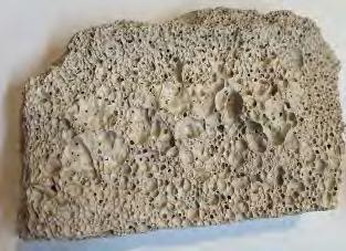
This is what Reinforced Autoclaved Aerated Concrete (RAAC) looks like.9
The product was first developed in Sweden in the 1930s, and although the use of RAAC is more common in Europe, the only RAAC sold to the Ontario market goes by the brand name of “Siporex,” which was manufactured by Domtar at their Montreal Plant from 1955 to 1972. Other RAAC products include Durox, Celcon, Hebel, Ytong, Aircrete, and Theramlite, some of which are now being imported into parts of Canada. Siporex panels used conventional steel reinforcement, coated with cement latex coating, to provide tensile and compressive strength to the panels. The product became popular in Canada due to its good insulating properties, which allow for insulation to be omitted from roof assemblies, acoustical properties, and lightweight nature, allowing for ease of construction, and was mainly used in schools, hospitals, commercial, and light industrial buildings. 5
Although it is called concrete, RAAC differs from conventional concrete in that has different materials and physical properties than conventional concrete. The aluminum powder reacts with water and lime to
create hydrogen gas, which creates uniform air bubbles throughout the concrete. These air bubbles give the concrete the appearance of looking like a sponge and significantly reduce the weight of RAAC to approximately 30 per cent of conventional concrete.6 These air bubbles also reduce strength of RAAC, as well as its ability to bond to steel reinforcement. RAAC does not use coarse aggregate, which also contributes to its reduced strength.7
RAAC DURABILITY CONCERNS
Prior to the 2018 collapse, a string of RAAC roof panel failures occurred in the UK in the 1980s, affecting panels initially installed in the 1960s.2 This temporarily halted the production of RAAC products in the UK and led to significant research being conducted in the early 1990s. Schools and other public building owners are being tasked with implementing a management strategy to address the safety concern posed by RAAC.
The primary durability concerns associated RAAC construction are listed next:
• RAAC has an effective service life of 30 years.8 Given that RAAC production in Ontario was stopped in 1972, all RAAC panels currently in place in Ontario are well beyond the end of their expected service life and are due for replacement.
• The porous nature of RAAC makes it highly susceptible to moisture ingress and carbonation. This vulnerability leads to moisture-related degradation and concrete carbonation effects such as shrinkage, sulfate attack, and leaching of cement hydrates.4 As such, all RAAC requires exterior weather protection.
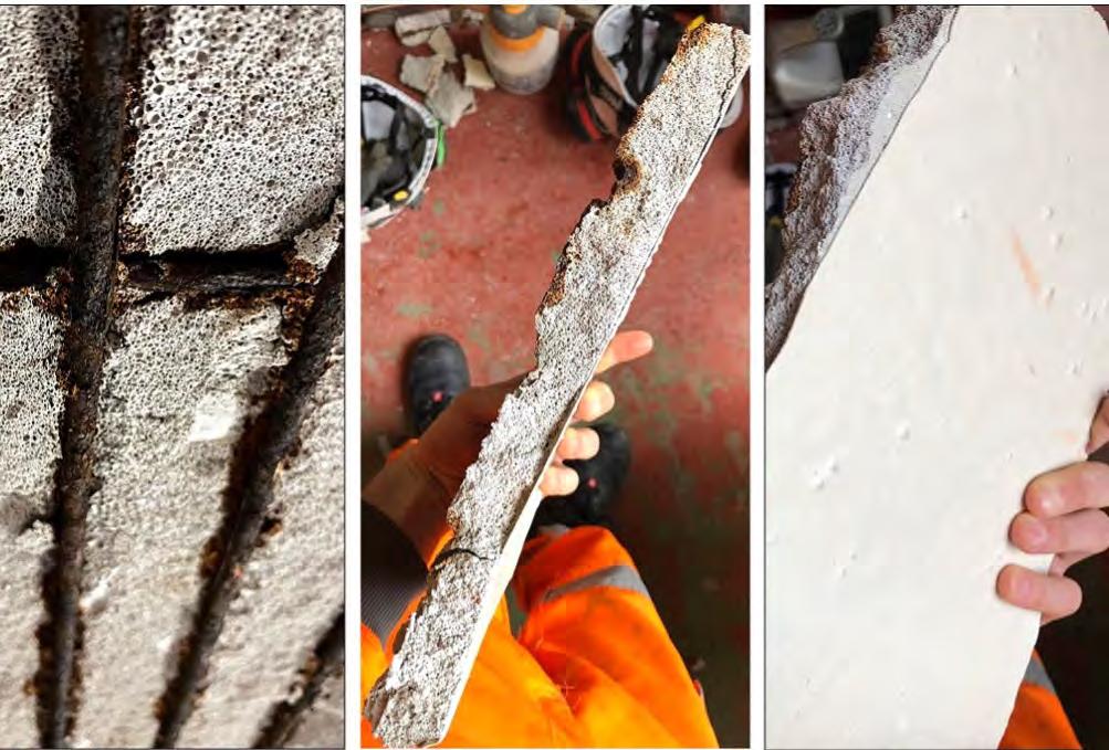
• This also compromises the alkaline protective layer that shields steel reinforcement within concrete, making it prone to corrosion from rainwater penetration and carbonation. To mitigate this issue, steel reinforcement in RAAC is typically coated with bituminous or cement latex coatings. However, assessments have revealed corrosion even in areas where these coatings appear visually intact, raising concerns about their long-term effectiveness.7 Corrosion of the steel reinforcement can occur without apparent cracks or


spalling occurring on the exterior of the RAAC due its high porosity and low compressive strength.8
• The low modulus of elasticity of RAAC causes it to undergo permanent creep deflection when subjected to loading. This increases the likelihood of water ponding on roofs, which further increases the loading and likelihood of moisture infiltration. This makes RAAC roof panels particularly susceptible to failure.
ASSESSMENT AND MANAGEMENT OF RAAC
The first step in identifying RAAC panels in Ontario buildings is to look at the age of the building. As noted previously, RAAC was only sold in Ontario from the mid-1950s to mid-1970s; therefore, buildings built outside of this range are unlikely to have been constructed with RAAC. Following these preliminary steps, RAAC can be visually identified as follows:
• Size: Siporex floor and roof panels were typically manufacturer to be 457 mm (18”) wide, 76 mm to 254 mm (3” to 10”) thick, and lengths up to 6.1 m (20 ft). Wall panels are typically 457 mm (18”) wide or 1,524 mm (60”) wide, 127 mm to 254 mm (5” to 10”) deep, and up to 6.1 m (20 ft) long. Masonry blocks are typically 229 mm x 257 mm (9” x 18”) and available in thickness from 75 mm to 254 mm (3” to 10”).
• Shape: RAAC panels typically have a chamfer or V-shaped groove at the edge of the panels.
• Colour: Light grey or off-white.
• Texture: Smooth or slightly textured surface. Porous/bubbly interior with no visible stones or aggregate.
• Weight and density: The weight varied from 9 to 30 lbs/ft2 and the density is approximately 25 to 37 lbs/ft3 (pcf), which are 20 to 25 per cent of normal reinforced concrete. It produces a somewhat hollow sound when tapped with a hard object.
• Strength: Compressive strength was originally specified to be 300 to 700 psi (25 to 27 pcf).
• Bowing and deflection: RAAC roof panels may bow or deflect. This can be most easily observed when there is differential bowing from one panel to another. Siporex literature denoted a maximum deflection of 1/360 of the effective span under the weight of applied loads.
• Softness: RAAC is soft and can more easily be scored with a screwdriver, screw or nail.
Once RAAC has been identified at the building, periodic structural assessments of the panels should be conducted by a licensed structural engineer. The structural assessment should include a review of deadload, including any potential changes to the roof assembly and/or mechanical equipment on the roof, measurements of deflections and end bearing distances, recording of defects including differential displacement, cracks, spalling, water leaks, resonant sounding of panels for evidence of debonded steel reinforcement, and recording of alterations made post construction. Localized intrusive openings and in-situ load testing can also be completed, with consideration for the potential damage that could be caused to the structure.5
Based on the results of the assessment, individual panels can be categorized based on their risk level. The report prepared by Rimkus recommends four risk categories: critical risk, high risk, medium risk, and low risk. Periodic roof condition assessment and moisture testing should also be performed by a qualified building enclosure consultant in conjunction with the structural assessment. Roofing assessments should include thermographic imaging, electrical capacitance, and destructive cut tests with moisture probe equipment.
The presence of RAAC construction is likely to affect more than just the school boards and other public entities which are currently implementing management programs for these structures. Those interested in learning more about the topic are encouraged to review the references listed to the right. n
Brandon Gemme is a Project Manager at Leading Edge Building Engineers in Vaughan, Ontario, Canada. He holds a Bachelor of Applied Science in Civil Engineering from the University of Toronto and is a licensed Professional Engineer in Ontario, specializing in building restoration. Brandon’s expertise encompasses evaluating, investigating, and remediating building envelope and structural systems. His involvement in numerous deep energy retrofit projects has equipped him with valuable experience in design, modeling, and project management.
REFERENCES:
1. Rushowy, K. (20244, June 27). Hundreds of Ontario schools with the same aging concrete as the Ontario Science Centre are at risk. The Toronto Star. https://www. thestar.com/politics/provincial/hundreds-of-ontario-schools-with-the-same-agingconcrete-as-the-ontario-science-centre-are/article_df6983d2-3251-11ef-862d-b361d337cf3d.html.
2. Benzie, R. (2024, June 21). Ford government abruptly closes Ontario Science Centre after report found roof in danger of collapsing. The Toronto Star. https://www.thestar. com/politics/provincial/ford-government-abruptly-closes-ontario-science-centre-after-report-found-roof-in-danger-of-collapsing/article_3e7a8442-2fd8-11ef-9c0003276c11fe83.html.
3. Lam, E. (2024, June 24). Ontario Science Centre doesn’t require full closure: A close reading of the engineers’ report. Canadian Architect. https://www.canadianarchitect. com/ontario-science-centre-doesnt-require-full-closure-a-close-reading-of-the-engineers-report/.
4. Petrolab Ltd. (n.d.). Reinforced Autoclaved Aerated Concrete (RAAC) – Basic Composition & Petrography. https://www.petrolab.co.uk/reinforced-autoclaved-aerated-concrete-raac-basic-composition-petrography/.
5. Caruso, F (1998). Lightweight, Autoclaved, Aerated, Cellular Concrete Roof Panels (LAACCRP): Structural and Re-Roofing Problems. Interface.
6. The British Reinforced Concrete Association (BAR). (2023). REINFORCED AUTOCLAVED AERATED CONCRETE (RAAC). https://www.uk-bar.org/news/ BAR-GUIDANCE-NOTE-REINFORCED-AUTOCLAVED-AERATED-CONCRETE-RAAC/113113.
7. CROSS-UK. (2019). Failure of Reinforced Autoclaved Aerated Concrete (RAAC) Planks. CROSS-Safety. https://www.cross-safety.org/sites/default/files/2019-05/failure-reinforced-autoclaved-aerated-concrete-planks.pdf.
8. Rimkus Consulting Group, Inc. (2023, September 4). Understanding the Historic Use of Reinforced Autoclaved Aerated Concrete (RAAC) in Building Construction in Ontario. Infrastructure Ontario. https://www.infrastructureontario.ca/49fd31/contentassets/84df22e71b7c40b2aaeef94da88c78b5/rimkus-white-paper---understandingthe-historic-use-of-raac-in-building-construction-in-ontario---2024-06-25.pdf.
9. Department for Education. (2024, April). Reinforced Autoclaved Aerated Concrete (RAAC) Identification Guidance. GOV.UK. https://assets.publishing.service.gov.uk/ media/6628e519b0ace32985a7e5ad/GUIDE-DFE-XX-XX-T-X-9002-Reinforced_ Autoclaved_Aerated_Concrete_Identification_Guidance-A-C04__002_.pdf.
10. HTA Building Investigations Scotland. (n.d.). RAAC Assessments. https://hta-building-investigations-scotland.co.uk/building-investigations/raac-assessments/.
Steel Corrosion in RAAC.10
The National Fenestration Rating Council Moves to a More Practical Condensation Rating

By Dennis Anderson, National Fenestration Rating Council (NFRC)
More than 20 years ago, the National Fenestration Rating Council (NFRC) and its membership developed the condensation resistance rating. While this rating was fair, accurate, and credible – consistent with all NFRC ratings – the rating only provided information to compare which products had the higher rating value.
The shortcoming of the NFRC condensation resistance rating was that the value could not be used to predict the likelihood of condensation forming on the product based on the following factors: relative humidity in the home, dew point temperature in the home, or expected exterior air temperatures during the coldest days of the year.
NFRC and its membership corrected that. The approved Index (CI) allows the consumer, manufacturer, building owner, or architect to find the fenestration product that reduces the potential for condensation based on where that window, door, or skylight will be in the United States or Canada.
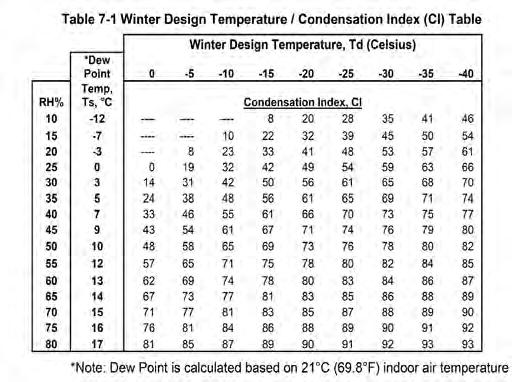
In 2018, Jeff Baker shared a research study by Hakim Elmahdy with the NFRC condensation resistance task group. The paper, “A Universal approach to laboratory assessment of the condensation potential of windows,”1 holds the key that resulted in the new NFRC Condensation Index (CI) rating. The CI rating provides the point at which the window will potentially form condensation. This allows the end user to determine the minimum CI rating needed to reduce the likelihood of condensation forming, using Table 7-1 (to the right) from the NFRC 501-2023: User Guide to the Procedure for Determining Fenestration Product Condensation Index Rating. The desired rating for a specific city or region in North America can be determined with two of the following three indicators: the winter design temperature, the relative humidity (RH%), or the dew point temperature.
DOES THE INDUSTRY NEED ANOTHER CONDENSATION RATING?
Our stakeholders have asked this question many times and we have all worked together to align our methods. The new CI rating
is now active and provides more value and flexibility for product designs than the legacy NFRC Condensation Resistance rating (sometimes mistakenly referred to as “CR”). NFRC has also worked with the CSA Group, formerly the Canadian Standards Association, to publish a revised the CSA A440.2/.3 in October of 2022 to add the ANSI/NFRC 500 simulation method for CI, which aligns with NFRC’s and CSA’s computer simulation method for a condensation index rating.
NFRC also participates in a task group at the Fenestration and Glazing Industry Alliance (FGIA) to potentially add a condensation index value via a physical test to the current AAMA 1503-09 test method that will also align with the ANSI/NFRC 500 tested condensation index rating.
That the three leading North American fenestration standard organizations are working together to alleviate any confusion or
Dennis Anderson.
Figure 1: Table 7-1 Winter Design Temperature and Condensation Index. Graphic courtesy of
concern with multiple condensation test methods and values is a good thing.
In August 2020, NFRC held a webinar titled Understanding the New NFRC Condensation Index2 that provided details for the practical use of the rating and offered insight into how the ratings from other organizations differ from each other.
Another source of information is the Condensation Resistance Task Group page,3 which includes links to the original paper by Hakim Elmahdy, research documents, and other information. Dennis Anderson, NFRC’s Senior Manager of Programs spearheaded this rating and can be reached at danderson@nfrc.org for more information. n
Dennis Anderson is the NFRC Senior Programs Manager.
REFERENCES:
1. National Research Council Canada. “A Universal approach to laboratory assessment of the condensation potential of windows.” Government of Canada. https://nrc-publications. canada.ca/eng/view/object/?id=ec8e38b6-41e4-4fdd-a02e4e01a7bcbef1.
2. The National Fenestration Rating Council. “Understanding the New NFRC Condensation Index Rating.” YouTube. https://www.youtube.com/watch?v=dBTN-mzWkxA.
3. National Fenestration Rating Council. “Task Groups: Condensation Resistance.” https://nfrccommunity.org/group/CRTG.


Shattering Glass: Unveiling the Hazards
By Adam Hosny, Capacity Engineering Limited
Nickel Sulphide Inclusions in Glass and Canadian Regulations
Iwas recently involved in a Forensic Engineering engagement regarding the investigation of a 55-storey building where more than 15 insulated glazing units (IGU’s) spontaneously shattered.
As Professionals we must recall that the Engineer shall regard the practitioner’s duty to protect the public welfare as paramount. As you can imagine, glass falling from 50+ storey height poses a substantial risk to public welfare. When public safety is at risk, it is crucial that you work with the Authority Having Jurisdiction (AHJ) to ensure any necessary measures are immediately taken to protect the public.
IGU’s in curtain wall assemblies serve multiple purposes, and their design and installation are governed by the Ontario Building Code (OBC) as follows:
1. The design of the window to take environmental loads are governed under Part 4 of OBC 2012 “Structural Design.”
2. Additionally, windows (mainly curtain walls and window walls) at the edge of a buildings slab act as a guard rail and must resist guard loads where glass is located under the minimum height requirement. Thus, they are also governed under Supplementary Standard SB-13 “Glass in Guards.”
3. The window acts as an environmental separation and the design is also governed by Part 5 of OBC 2012 “Environmental Separations.” Part 5 also refers the designer to Part 4 of the OBC for environmental load calculations.
4. Additionally, the curtain wall is subject to testing under the North American Fenestration Standard/Specifications (NAFS) for Windows Doors and Skylights and
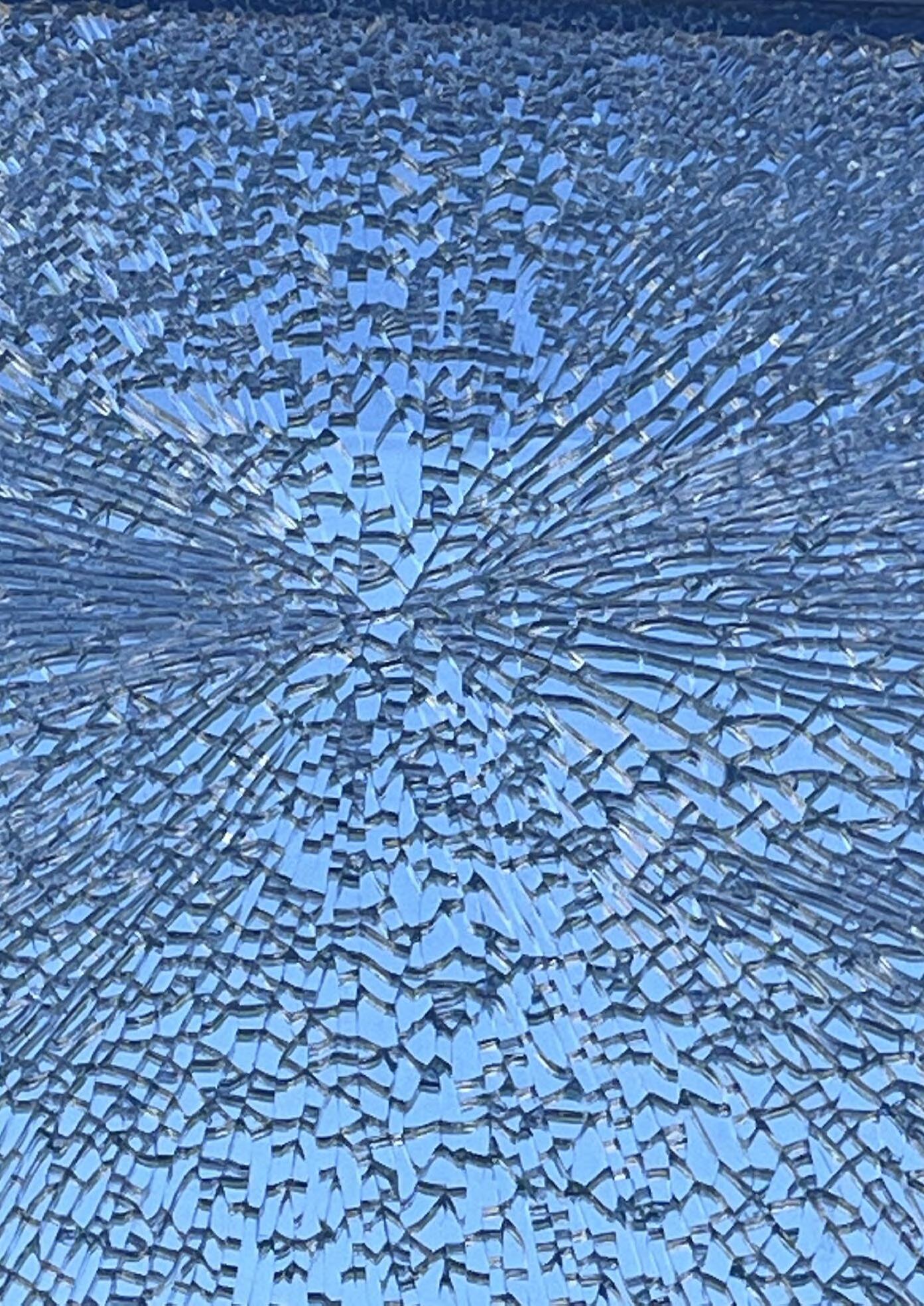
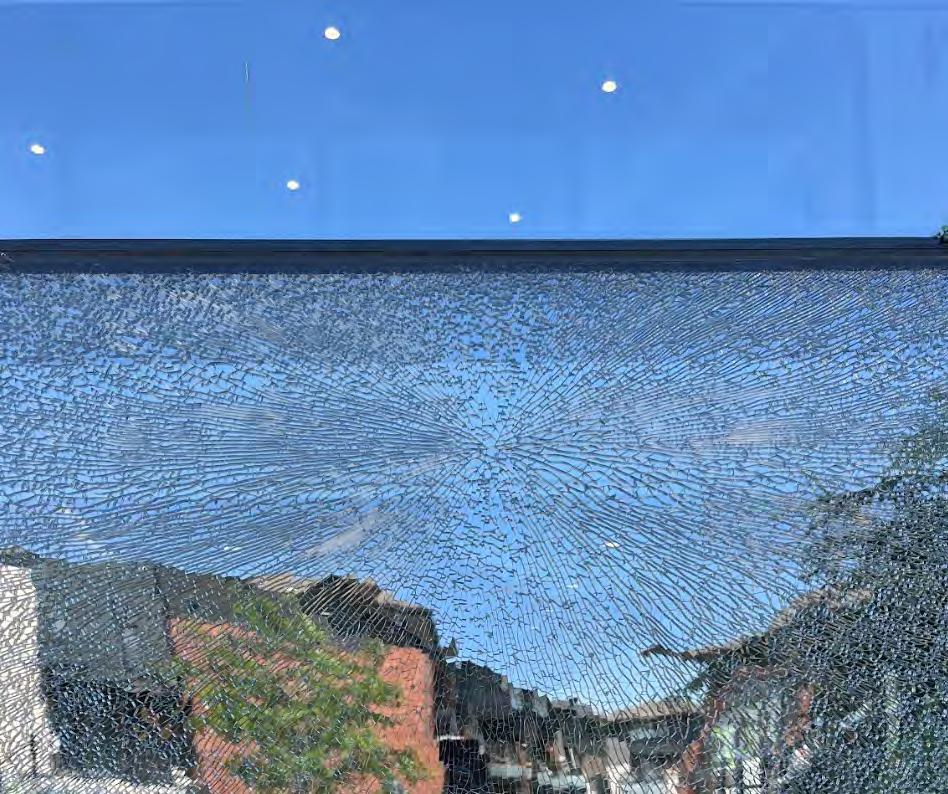
The unique butterfly crack shatter pattern is an indicator of the NiS failure.
meet the requirements of CSA A440S1. This testing is intended to ensure that the windows meet structural performance requirements as well as control of air leakage, condensation and rain penetration.
5. The installation of windows are governed by CSA A440.4 “Window Door and Skylight Installation.”
There are several factors that could cause glass in curtain walls to break. In some cases, it could even be a combination of several factors. Some factors include:
• Environmental loading: Excessive wind loading.
• Size: Columns shorten under axial load over time. If not properly considered, the
shortening of the building can compress the curtain wall frames and shatter the glass.
• Size: Breakage due to excess temperature change and lack of expansion and contraction constraints.
• Size: Edges of glass being damaged.
• External impact: Sudden impact loading such as bird strike, debris, etc.
• Nickel sulphide inclusion: An impurity in the material that occurs during the manufacturing process.
While each of these factors must be explored, this glass breakage was most likely due to the occurrence of nickel sulphide inclusions (NiS).
WHAT IS NICKEL SULPHIDE INCLUSION (NIS)?
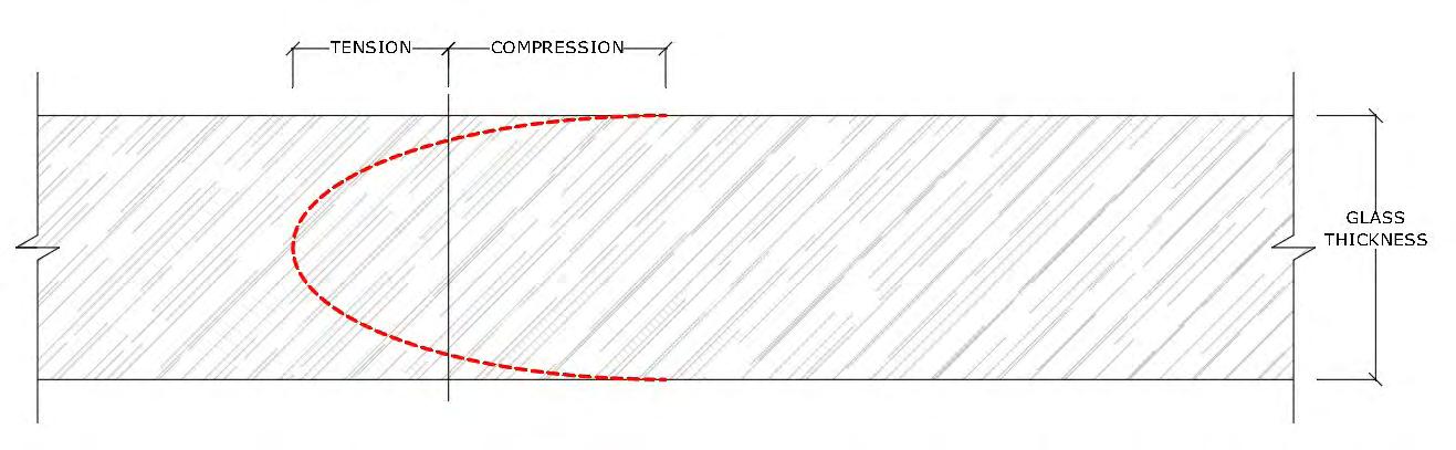
To properly understand NiS, it is important to understand the process of manufacturing tempered glass. To produce tempered glass, annealed glass is heated to a temperature of ~600°C, then quenched. High-pressure air blasts the surface of the glass to cool the outer surfaces rapidly relative to the center. As the center of the glass cools, it tries to pull back from the already cooled outer surface. This causes the center to remain in tension with the outer surfaces having a counterbalancing compression stress. After tempered glass is formed, the stress profile through the thickness of the glass becomes parabolic as seen in Figure1.
With the original Annealed Glass, there is a possibility that a nickel sulphide stone forms in the tension zone due to nickel contamination. These stones can vary in size from 0.05 mm to 0.1 mm. When the resultant tempered glass exposed to varying temperatures in the field, the NiS inclusion changes in size and can grow such that internal tensile stresses exceed the counterbalancing compression stress and shatter the glass. The highest risk of occurrence is in the first 10 years of the tempered glass life.
The event is loud (shatters at the speed of sound), with the light breaking near instantaneously into thousands of tiny pieces.
HOW TO DETERMINE A NIS FAILURE
If a light shattered due to NiS inclusion, there is often a tell-tale: “The Butterfly Effect” or a “Butterfly Pattern.” The Butterfly Effect is the phenomenon that the world is interconnected such that one small occurrence can cause major consequences in a
Shattered glass due to a nickel sulphide inclusion failure. Photos and graphics courtesy of Adam Hosny.
Figure 1: Tempered glass formed through the stress profile of the thickness of the glass, which becomes parabolic.
Location of Glass in a Guard
TABLE 2.1.1.1.
SELECTION OF GLASS IN A GUARD FORMING PART OF SENTENCE 2.1.1.1(2)
Glass located beyond the edge of a floor or within 50 mm of the edge of a floor.
Glass located more than 50 mm inward from the edge of a floor.
Glass located more than 150 mm inward from the edge of a floor.
Type of Glass Required
Heat strengthened laminated glass.
Heat strengthened laminated glass.
Heat soaked tempered glass.
Heat strengthened laminated glass.
Heat soaked tempered glass.
Tempered glass not more than 6 mm thick.
Column 1 2
much larger, complex system. Similarly, we often invoke St. Venant’s Principle: local vs. Global effects. One must consider the local aspects of a structure as well as the global; both must be carefully considered.
With respect to a NiS failure, the Butterfly Effect yields the Butterfly Pattern. A small (0.05 mm to 0.1 mm) NiS inclusion causes the failure of the entire IGU. Ironically the origin of the glass failure resembles a butterfly. The fracture starts with a small straight line, then branches out on each side and continues to branch repeatedly in a chaotic manner. This unique shatter pattern provides strong evidence of NiS. With reports of a loud bang, it is near definitive. Best practice is to confirm NiS through laboratory testing.
HOW DO WE PREVENT THIS ISSUE?
Prevention may not be possible. Risk of NiS breakage may be reduced through heat soak testing. This involves sustained heating of the tempered glass to between 200°C to 300°C. This test accelerates the growth of the NiS inclusion in attempt to purposely shatter the glass. While expensive, this has been showen to significantly reduce the risk of NiS induced breakages.
Currently there is no North American standard for heat soak testing, however, industry best practice and SB-13 requirements are to perform the heat soak test to the European Standard EN 14179-1.
HOW DOES OUR CODE ADDRESS THIS ISSUE?
Prior to the 2012 OBC, buildings in Ontario were allowed to employ simple
tempered glass IGU’s. This changed after several high-profile failures from 2010-2012 in Toronto caused the Ministry of Municipal Affairs and Housing (MMAH) to act. The MMAH studied the issue through industry engagement and released Supplementary Standard SB-13.
The objective of SB-13 is to provide requirements for the design and construction of glass in guards and reduce the probability of breakage of glass panels and injury to persons in the vicinity of a building as a result of failing broken glass. The requirements of SB-13 is now listed in Figure 2.
This table under SB-13 provides requirements in Ontario that all glass near the edge of a buildings slab be heat strengthened laminated or heat soaked tempered.
CEL was involved in the forensic investigation of the high-profile failures in Toronto which caused MMAH to develop this supplementary standard. The simple truth is that at the time of construction, the tempered IGU panels met all OBC requirements. It is
the failure of the code to address a serious concern which lead to SB-13.
IGU’s and curtain walls are an evolving area of professional practice for Engineers and Architects. As research progresses, so must our Code evolve. The main objective of the Code, as set out in Division A, Part 2, is to limit the probability that as a result of design or construction, a person in or adjacent to the building will be exposed to unacceptable risk or hazards. We, as Professionals, must continue to advance the profession with our knowledge and expertise to further protect public safety. n
Adam Hosny, M.Eng., P.Eng., is a Structural Engineer & Partner at Capacity Engineering Limited. His practice focuses on Structural Engineering with a special interest in Building Envelope design, failure diagnosis, and testing. In his role at Capacity Engineering, he is responsible for structural and building envelope forensic investigation, structural design, and is the lead engineer on Tarion RB 19R reviews.
Figure 2: Table 2.1.1.1 of Ontario Building Code Supplementary Standard SB-13 “Glass in Guards.”
Beyond Electricity: Application of Copper Alloys for Dome Roof Construction
By Nensi Baboci, RJC Engineers
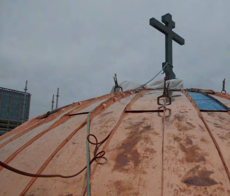
Copper dome roofs are among some of the oldest roofing systems employed in historic and modern building construction. The use of copper in roofing dates back to the original Pantheon constructed circa 27-25 BCE in Rome, Italy and has since been employed on various monumental and heritage buildings around the world. The Holy Trinity Russian Orthodox Church in Toronto, Ontario, is a unique local case study where this historic roofing material was used to rejuvenate a city landmark.
The church was originally constructed in 1922 as a Jewish Synagogue by Architect Benjamin Brown in the Romanesque architectural style and was partially reconstructed in the Russian Orthodox style between 1966 and 1969 and listed as Heritage Property in Toronto in 1973. There are also two small wood-framed towers at the northwest and southwest corners of the building that employ

a painted lead-coated copper cladding and are complete with two small copper domes each approximately 160 square feet in size.
The main roof features a large central woodframed copper dome roof of approximately 1,500 square feet that extends beyond the center of the main low-slope roof.
An evaluation of the existing roofing systems revealed the existing copper roofing appeared to be of original construction and had reached the end of its service life. The project team recommended wholesale roofing replacement of both the low-slope roofing systems and the copper domes with profiles matching existing to keep the heritage defining character of the building, and design was started.
One of the design considerations of copper roofing was the tendency of the thin copper sheets to buckle when they are compressed and result in what is known as oil canning of the copper sheets. This phenomenon, which is common to all crafted metals, can occur due to a combination of many factors, which cannot be controlled at any period, but
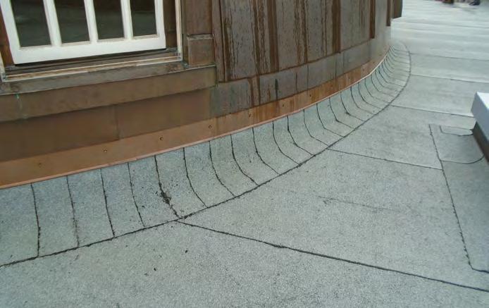
View of tie-in detail at the bottom of the dome to permit future low-slope roof replacement.
Aerial view of the main roof and two west towers at Russian Holy Trinity Orthodox Church during the construction of the central copper dome. Photos courtesy of RJC Engineers.

can be reduced with proper design considerations and the employment of knowledgeable heritage restoration contractors.
Copper is known for its high resistance to corrosion due to its ability to reach weathering equilibrium by forming a patina layer when it encounters weathering agents, which, over time, give it its well known-green coloration. This allows the copper to maintain a long service life with relatively low-maintenance compared to modern membrane-type roofing systems.
One of the design challenges of this project was to ensure that the transition between the bottom of the copper dome to the lowslope roof below would permit future lowslope roofing replacement. The intent of the design was to allow low-slope roof replacement without having to modify any parts of the copper dome, while providing sufficient clearance for future increase in the low-slope roofing insulation levels. In addition, given the ability of copper to react with dissimilar metals, it was important to select the proper flashings during the design of the tie-in detail between the roofs.
The design of this project utilized thinner and more malleable copper sheets to construct the more elaborate decorative elements of the central and tower domes, compared to the thicker and heavier sheets used for the construction of the primary dome roofing systems. In addition, copper alloys, such as lead-coated copper (LCC), were used in applications where the client preferred the long-term appearance of the copper to resemble the color of lead (dark grey) and in
applications where the client planned to paint or coat the copper in the future, as LCC often does not require additional surface treatment prior to coating. Consideration for underlayment membrane products and detailing was also of high importance, as copper roofs can reach high temperatures which can readily degrade typical roofing membranes.
Copper dome roofs provide long-lasting protection and beauty to heritage buildings.
It is critical to have a good understanding of the material properties, installation methods and design challenges of copper dome roofing systems as well as employ knowledgeable craftsmen to ensure they are properly installed for long-lasting performance. n
Nensi Baboci, B.A.Sc., M.Eng., P.Eng., is a Project Engineer at RJC Engineers.
Copper dome roofs provide longlasting protection and beauty to heritage buildings.
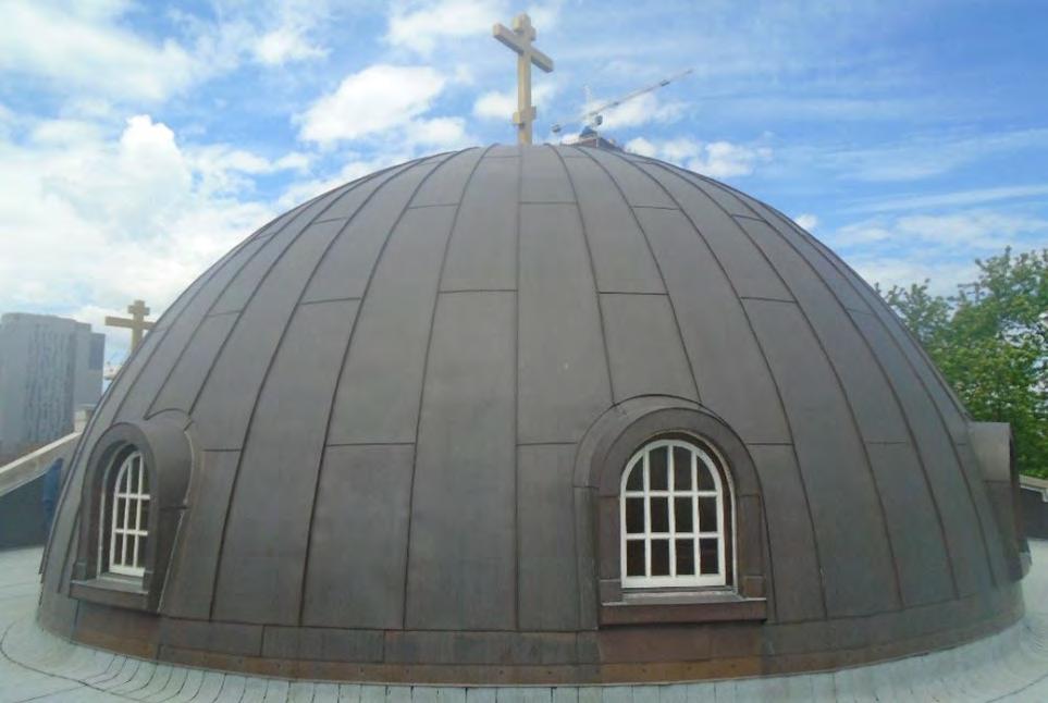
Overview of completed central copper dome.
View of thick copper sheets at the central copper dome during construction. View of hand seaming underway during construction.
Siloed Codes and Siloed Design: What is Most Important?
By Anton Van Dyk, Layton Consulting

Have you ever had an argument or debate with someone on what is most important? Have you just gone around in circles getting nowhere as you both saw your bias as most important? A few yeas ago I was introduced to a “context” exercise. It was designed to bring awareness that with the lack of context both can be right and both can be wrong. The exercise uses fruit. By asking “what is the best fruit?” you can get a plethora of answers and a debate will ensue. Now if I ask, “what fruit has the most vitamin C?” it will narrow the answer down and reduce the overall debate to the facts. You’d be surprised to find out that it isn’t orange or lemon, but guava!
Now let’s bring this idea into our industry. If I asked “What is a high-performance window?” I would get Passive House, U0.8, U1.22, triple glazed, low SHGC, high SHGC, OITC 35, PG50, Class CW, tilt and turn, casements vs. sliders, European product, and the answer just kept flowing. The issue was, I put no context to the question. What that did was gave me a perspective of what the individuals in the audience determined what was most important to them. My goal was to flush out the bias in the room.
With this in mind, I started to see natural trends pop up in other meeting with manufacturers, designers, and regulators. What everyone felt was most important would dominate the situation and in some cases at a negative outcome to another individual needs. We were having a “best fruit” debate about building materials.
So, I started to call this Siloed Design or Siloed Codes. This is where an individual amplifies what they feel is most important in the moment without understanding the impact of another individuals needs. Like in any relationship, give and take is fundamental. Without empathy, you are going to struggle to get your point across.
As more and more regulators adopt “climate emergency” policy into codes and standards, you will see a trend in codes move in this direction, but at what consequence. Two good examples that I see too often is when an acoustic design for windows demands a ¾ inch to 1 inch air space in the insulated glazing unit (IGU). This will introduce convection currents in the air space resulting in a reduction in U value performance. Maybe to a level that no longer applies to the Step/Tier code. When you renovate a window from double to triple glazing, the sash size may be reduced due to weight limits for durability on hardware and the operable window no longer meets egress. In this case, an individual must determine what is most important: energy or life safety. For some this might appear obvious, but I have heard
We cannot take what is most important to one individual and run with it. Like any change in any business, knowing its impact on people and the overall community is step one.
individuals say the “climate emergency” is also life safety. There is no simple answer other then recognizing first that there are multiple needs to be met.
Another example is when regulation and/or design pushes you into a high-risk environment. For example, the move towards project specific thermal modeling for more accurate U values and solar heatgain coefficient (SHGC) ratings is trending for total home energy calculations. This is a move away from standardization using the National Fenestration Rating Council (NFRC) or the Canadian Standards Association (CSA) rating for a manufacturer. Now their outcomes in performance must be calculated for each project. This will put risk onto a manufacturer that they meet the actual targets they are not used to providing as the industry has functioned using standardization such as NFRC values performed by a lab.
The other high risk that this triggers is a contractual risk. When you move away from standardization in performance metrics such as NFRC, a manufacturer will need to provide a product cost that meets a project specific outcome. The question is, when is this calculation done, before a contract is signed or after? In theory, this needs to be done before, but that will add significant costs to the estimating process, driving up overheads and increasing construction costs. Or it can be done after a contract awarded, which brings on risk in the event that the manufacture cannot hit the project specific outcome with their frame and glass features.
The third example is a recent one where I was asked to review a new “wildfire reliance” code that would be implemented in regions at risk of wildfire. When I saw the fenestration section, I realized very fast that the product they were requiring to be used, would struggle to meet the U value requirements that the building codes were mandating.
The new debate is fall production vs. egress. This one is still being debated at a high level and as it comes with the risk of people falling out of buildings and people not being able to escape from a building in case of fire, you can see how hard this decision is.
These are just a few examples of why any change in how we function as an industry needs a full spectrum assessment of all impacts. We cannot take what is most important to one individual and run with it. Like any change in any business, knowing its impact on people and the overall community is step one.
My goal in the industry is to be the voice for the integration of what is required and to assist with how the decision is made on what is most important. We cannot ignore one issue for the benefit of another so all we can do is be educated on their impacts and use this to make good decisions as a team. This is why I stress importance on knowing the code and how to use the code to make decisions. n
Anton Van Dyk has over 25 years of building envelope related consulting and construction experience which includes consulting on multi-million dollar building envelope rehabilitation projects on existing occupied buildings and small scale repairs. New construction experience consists of mixed use wood and concrete frame construction for low and high rise buildings along with specialty projects such as an addition to a library, and the design of a modern performing arts centre.
As Building Codes have evolved at a rate faster than ever, Anton's current focus is assisting fenestration manufactures, specifiers, and installers understand the paths of code compliance in British Columbia and throughout North America. Anton has worked with multiple window and glazing products ranging from curtain wall, window wall, storefront, fiberglass and vinyl tilt-and-turn, and common nail-on flange windows. He has helped develop window testing protocols and is actively involved in the field testing of windows.

Strategies for Urban Flood Mitigation
By Ariel Zhu, Building Science Expert
Risk and Performance of Stormwater Detention Assemblies
Urban flooding results from dense urban development, reducing permeable surfaces and intensified precipitation due to climate change. This strain on outdated sewage systems necessitates strategies such as permeable pavement, detention ponds, and enhanced greenery. Vegetated Roofing Assemblies (VRAs) and Stormwater Detention Assemblies (SDA) are particularly advantageous in urban settings because they are implemented on roofs which occupy substantial areas within cities. VRAs manage stormwater by retaining it and facilitating drainage through mechanisms like evaporation and evapotranspiration, rather than overloading drainage systems. However, these assemblies come with unique challenges such as roots puncture, organic growth, and high maintenance requirements.1 Despite these risks, VRAs have long been valued for their effectiveness in stormwater management. To reduce some of
the risks while obtaining similar results, the opportunity of using surfaces for non-vegetated assemblies is explored. This research was supported and facilitated by the National Research Council Canada and Toronto Metropolitan University.
SDAs capture and detain water on the roof, releasing it over time through the same original path to reduce peak flow into the municipal sewage system. Building elements have historically been designed to diverge water away from the building. Many new risks accompany the extensive submersion of roofing membrane, which can be found mostly in practitioner’s guides on avoiding roof ponding.2 Risk considerations of installing an SDA include structural capacity, contaminant growth, ice dam and damage, wind uplift, and change to roof membrane.
In the Ontario Stormwater Management Planning and Design Manual, rooftop storage was identified as an economical strategy
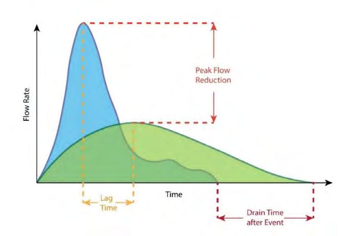
for flat building roofs, as it holds more detainable volume than steep sloped roofs.3 Besides the low-slope roofing system, the SDA system consists of water detention components and the drainage system, and it is by these two components, that the SDAs are categorized.
Water detention components can be categorized by two functionalities.4 First, the ponding device differentiates between the Roof-Integrated Design (RID), which captures water directly on the roof membrane itself, utilizing the roof as a basin for ponding; and the Modular Tray Design (MTD), which uses additional assemblies. These trays typically feature a small orifice at the bottom to regulate the flow rate of water. All systems are simulated effective in detention. RID employs less material in its composition, but risk prolonged submersion of membrane underwater. MTD does not change membrane function but have its risks in additional loading and wind uplift.
Secondly, drainage methods can be classified as either active or passive. An active system can adjust its flow rate through actuation, whereas a passive system remains fixed once installed. The MTD and check dams function as a passive system in this context. An active modified drainage inlet includes a valve that can be operated to control water ponding,5 while a passive modified drainage inlet incorporates a flow control weir to naturally slow down the flow rate.
Active Modified Drainage Inlet (aMDI) systems replace conventional roof drains with remotely operated ones, allowing controlled water retention on rooftops. This study simulated three aMDI methods using water depth sensors on the same building under varying storm events. Method A fully drains the roof at designed ponding height, then re-drains
Figure 1: Typical hydrograph illustrating the criteria of evaluation. Graphics courtesy of Ariel Zhu.
as needed. Method B maintains ponding at designed height by intermittently releasing excess water, similar to an overflow drain. Method C integrates weather prediction to pre-emptively drain anticipated rainfall. The aMDI systems are simulated with two isolated rainfall events, where the second one starts two hours after the initial (see Figure 2). All methods effectively reduced peak flow by displacing it outside typical drainage periods. Method C excelled in peak flow displacement by draining before storm events, contrasting with Methods A and B which aligned drainage with storm peaks. Method B showed slightly lower volumetric outflow. These findings support aMDI’s potential for stormwater management but presents the practical challenges of integrating weather forecasting modules due to the cost and the maintenance requirements. Standardized assessment criteria are crucial for comparing aMDI effectiveness and optimizing their implementation on urban rooftops.
Passive Modified Drainage Inlet (pMDI) systems install a weir with an orifice at the drain level to slow water movement. However, this system cannot be modified unless removed. Three simulated pMDI designs were simulated with orifice flow equation, two with different numbers of the Zurn Control-Flo parabolic shaped weirs,6 and one with a PVC pipe insert on an existing drain. All pMDI system showed unexpectedly high detention performance with peak flow reduction of 95 to 98 per cent, lag time of 20 to 30 minutes, and drain time after event of 3.5 to 10 hours. This contrasts significantly with existing pMDI installations, where a various amount of 60 to 90 per cent peak flow reduction was recorded over two years, one of the weakest performances out of the assemblies.
MTD installs plastic trays with orifices on the bottom to slowly release water onto the roof and therefore, into the municipal sewerage system. Different components can be changed on this system to modify the performance of MTDs. For the simulation, four different components are explored within an array of 12 tests, comparing the effect of orifice size, tray size, absorptive materials, and roof coverage. All configuration improvement – smaller orifice size, larger tray size, additive absorptive material, and larger roof coverage – were able to achieve significant peak load reduction, ranging from 66 per cent to 73 per cent, while the absorptive
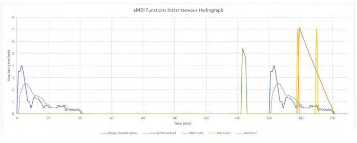
material and roof coverage displayed the largest mitigation performance.
Several notable examples of SDAs exist, each showcasing different performance outcomes.4 For instance, Credit Valley Conservation implemented an aMDI system coupled with water filtration, extending detention times beyond regulatory requirements.5 This system also serves as a secondary basin for rainwater harvesting, enhancing its grey water reuse performance. Similarly, Metropolitan Ave. in NYC studied various SDAs including MTD, pMDI, and check dams, with MTD demonstrating the most consistent and effective performance among them.7
In this study, the focus is on the detention performance of SDAs for urban flood mitigation, emphasizing peak flow reduction, lag time, and drain time after event. Regional sewage capacity, which wasn’t part
REFERENCES:
of this study, is another crucial factor of performance. Roof slope is also overlooked but would realistically significantly impact RIDs due to varying ponding depths. MTD performance can also hinges on material properties, which was not accounted for. Further research can refine guidelines for SDA implementation. n
Ariel Zhu is a recent graduate from Toronto Metropolitan University (former Ryerson University) with a Master of Applied Science in Building Science. Her thesis study focused on the risk reduction design of the storm-water detention assembly to mitigate urban flooding. Starting her professional studies in Architectural Design, Ariel now marries her experience in design with her interest in sustainability and retrofit as a Project Coordinator in the Building Science Industry.
1. Green Roof Guidelines - Guidelines for the Planning, construction and maintenance of Green roofs. Bonn: Forschungsgesellschaft Landschaftsentwicklung Landschatsbau, 2018.
2. Johnson, Steve. “Ponding Water on Flat Roofs; Common Problems & Best Solutions.” Roof Hub, September 2, 2022. https://myroofhub.com/flat-roofs/water-ponding/.
3. Stormwater Management Planning and Design Manual § (2003). https://www.ontario. ca/document/stormwater-management-planning-and-design-manual-0#section-0.
4. Jandaghian, Zahra, Yingxin Zhu, James Saragosa, Hitesh Doshi, and Bas Baskaran. “Low-Sloped Rooftop Storm-Water Detention Assembly to Mitigate Urban Flooding.” Buildings 13, no. 1 (December 21, 2022): 8. https://doi.org/10.3390/buildings13010008.
5. Surowiec, Bernadeta, Rohan Hakimi, Cathrin Winkelmann, Cassie Schembri, Phil James, Asif Bhatti, Kyle Vander Linden, and Bill Trenouth. “Automated Real-Time IoT Smart Blue Roof Systems for the ICI Sector for Flood and Drought Resilience and Adaptation,” June 2020. https://sustainabletechnologies.ca/app/uploads/2020/07/ Smart-blue-roof-feasibility-study_Jul2020.pdf.
6. Control-Flo Roof Drain. Accessed July 15, 2024. https://www.zurn.com/products/building-drainage/roof-drains/control-flow/z105.
7. Bloomberg, Michael R, and Carter H Strickland. NYC Green Infrastructure Plan: 2012 Green Infrastructure Pilot Monitoring Report, 2012. https://www.nyc.gov/assets/dep/ downloads/pdf/water/stormwater/green-infrastructure/2012-green-infrastructure-pilotmonitoring-report.pdf.
Figure 2: Hydrograph of aMDI systems.


2800-14th Ave., Suite 210
Markham, ON L3R 0E4
Tel: 647-317-5754
Fax: 416-491-1670
Email: info@obec.on.ca
obec.on.ca
Since 1987 the Ontario Building Envelope Council (OBEC) has been bridging the gaps amongst the architectural, engineering, research, manufacturers, and construction communities. Their non-profit organization addresses today’s challenges facing building performance and sustainability.
One of OBEC’s keys to success is their dedication to building science education at all levels.
Guided by the Board of Directors, OBEC is focused on delivering:
• Information forums for the exchange of ideas and information on building science
• Access to current technical information and best practices
• Educational programs for the benefit of the building community
• Guidance on current trends and issues to the research and development community
• Recommendations regarding improvements to codes and standards
Educational opportunities exist through conferences, technical forums, field trips, and monthly dinner presentations. This information is made available to members of OBEC. Members can be individuals, corporations, students, or members marked as Professional for holding a BSS designation.
Corporate Membership - A Corporate Member may be named as such if the member is a corporation, an individual to act as its representative at any meeting of members of the Corporation must be named as the Corporation’s main representative.
A Corporate Member is entitled to five (5) named persons to be listed in the membership database to receive all society notifications as well a copy of “Pushing The Envelope Canada” magazine. All company employees are eligible to receive the member rate for events.
Individual Membership - An Individual Member may be designated as such if the member is an individual person.
Student Membership - A student is an individual attending a recognized building science program at a college or university program full time.
Join OBEC and join hundreds of other like-minded people in your industry. Submit your membership application today and open the door to so much more.
Complete this application ONLY if you are paying via Cheque u Payment by Credit Card online at: https://obec.on.ca/member_applications
Select a Membership Type: Individual
- $219.00 + $28.47 HST = $246.47 Corporate Membership - $789.00 + 102.57 HST = $891.57
HST/GST # 124383076 RT0001
Select a Vocation: (select all that apply) Architecture Contracting Consulting
Education Engineering Supplier
Government Manufacturing
Other:
This section must be completed in order for the membership application to be processed. OBEC communicates with its membership via e-mail; in accordance with the Canada anti-spam law that came into effect July 1, 2014 you must indicate whether you wish to receive electronic correspondence from us.
INDIVIDUAL AND STUDENT MEMBERSHIP DETAILS:
Mr. Ms. Mrs. Dr. Prof. Other Name:
Company or School if Student:
I agree to receive electronic correspondce I DO NOT wish to receive any electronic correspondence. Signature: Date:
CORPORATE MEMBERSHIP DETAILS: Company: Address:
1. Mr. Ms. Mrs. Dr. Prof. Other
Name:
Title: Telephone: Fax: Email:
I agree to receive electronic correspondence Signature I DO NOT wish to receive electronic correspondence Date
2. Mr. Ms. Mrs. Dr. Prof. Other Name: Title: Telephone: Fax: Email:
I agree to receive electronic correspondence Signature I DO NOT wish to receive electronic correspondence Date
3. Mr. Ms. Mrs. Dr. Prof. Other
Name:
Title:
Telephone: Fax:
Email:
I agree to receive electronic correspondence Signature I DO NOT wish to receive electronic correspondence Date
4. Mr. Ms. Mrs. Dr. Prof. Other
Name:
Title:
Telephone: Fax:
Email:
I agree to receive electronic correspondence Signature I DO NOT wish to receive electronic correspondence Date
5. Mr. Ms. Mrs. Dr. Prof. Other
Name:
Title:
Telephone: Fax:
Email:
I agree to receive electronic correspondence Signature I DO NOT wish to receive electronic correspondence Date
Payment Information: Cheque payable to OBEC and mailed to: OR Payment by Credit Card online only at: 2800-14th Ave., Suite 210 https://obec.on.ca/member_applications Markham,