34 minute read
PLUMBING Up the ante with cross connection control certification
By Fred Bretzke
PLUMBING
UP THE ANTE WITH UP THE ANTE WITH

Cross connection control is a very important part of public safety and never more so than during these pandemic times. In western Canada, it’s the Western Canada Section of the American Water Works Association (WCS AWWA) that is the governing authority of cross connection control (CCC). We saw it come to Calgary in 1984 while I was a fourth-year apprentice at SAIT. Since then I have been CCC-certified and I have taught the cross connection control course for many years. This is a handy certification to possess. As I tell my students, if you are CCC-certified you are an even more employable technician, especially if you own a CCC test kit.
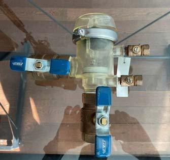
Let’s play CCC service technician for this article and see what we can learn. When it comes to CCC devices or repairs, it’s all about being transparent to customers. There are many devices but only three testable devices, which are tested annually, or on new installations, or reinstallations, or when repairs are made. These include the pressure vacuum breaker (most often used for irrigation systems), the double check valve assembly (DCVA) and reduced pressure (RP) backflow devices. For the purposes of this article, we’ll focus on the DCVA and the RP. DCVAs are typically used for premise isolation on commercial buildings. They are required for moderate hazards in non-health conditions. These devices protect the public water mains from any possible pollutants, including discoloured or distasteful water, cross connecting into them. You will find most DCVAs in the mechanical room just downstream of the water meter bypass. In order to explain how to repair these devices, one should first know the test procedure.
THE DOUBLE CHECK VALVE ASSEMBLY (DCVA)
DCVA TEST PROCEDURE
The following is the AWWA test procedure for a DCVA.
Test Procedures for Double Check Valve and Double Check Detector-type Assemblies using a Differential Pressure Gauge Test Kit:
Check Valve #1 and Check Valve #2 Performance Criteria: The check valves shall be loaded internally so that when the supply pressure is at least 1 psi and the outlet pressure is atmospheric, each check valve will be drip-tight in the normal direction of flow. [AWWA C510 Sec. 4.3.2.1]
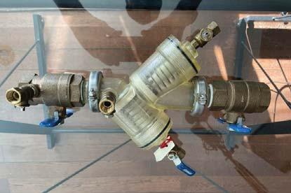
To test check valve #1 and check valve #2 for tightness in the direction of flow, and determine the static pressure drop across each check valve using a differential pressure gauge test kit.
This is accomplished by: • Connecting the differential pressure gauge to the upstream side of the check valve being tested. The test gauge centre line must be held at the same level as the downstream test cock reference point (outlet of the test cock or the water level if a sight tube is used).
• Closing both shut-off valves on the DCVA to isolate the pressure within the assembly. • Releasing water downstream of the check valve so the pressure is reduced to atmospheric.
• When flow from the downstream test cock ceases and the differential pressure gauge reading has stabilized, record the psid across the check valve.
• The check valve should be holding tight at a minimum of 1.0 psid or greater.
Basically, this means that you are testing the pressure differential (through the hose connections) between the two internal check valves. If these pressures differential exceed one psi the check valves need to be checked, repaired or replaced.
THE BEST LEAKS IN LIFE ARE UNSEEN
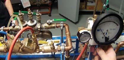
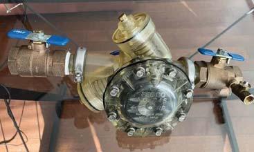
There is a saying: “The best things in life are unseen;” you could also say the best leaks in life are unseen, especially with the DCVA. If a DCVA is leaking, it leaks internally and the only way you can detect it is by doing a CCC test. Quite often these devices could leak on new installation if they haven’t been flushed enough through the spring check valves. This is why they are required to be tested on new installations. The problem with unseen leaks is there has to be a level of trust between the customer and the tester. Many years ago, when the servicemen at my plumbing company were testing approximately 2,000 devices annually, the issue of trust came up. One of our property management customers did not believe our technician when he failed the DCVA device. When you fail a device, you are to notify the city and the property owner that it needs to be repaired. What could be wrong with it? It could be a worn brass housing, or a chip or crack in the actual check, or a worn spring, or just sediment lodged in the seat of the check. The property owner didn’t believe the test and hired another plumber who was a friend of his to test it. His friend claimed it passed, but he probably didn’t even test it, let alone repair it. I phoned the chief CCC inspector at the time, and he wanted to help me, but insisted it is possible for the device to fail with sediment lodged in the check valve and then pass later if the sediment got pushed out through pressure. This tells us that testers must be honest when they test by actually doing the test and not just filling out the form, and owners must trust their plumbers. Typically, when repairing CCC devices, you should have a healthy stock of parts from various manufacturers, including Watts, Zurn
Wilkins and Conbraco. Most CCC devices have spring checks but some devices use compound check valves that work like a compound bow. You usually only need a crescent wrench, slot screw driver and Philips screw driver and of course, a test kit to complete repairs. Remember the best service tech is the one who has the right tools to do the job. The most common leaks occur when the check or Testing the DCVA pressure differential in a SAIT lab. seat is scarred. The springs on the DCVA are the same coil pressure and are easy to attain or switch. If a device fails you are required to eventually pull it apart, repair, and retest all at the customer’s cost.
THE ULTIMATE DEVICE
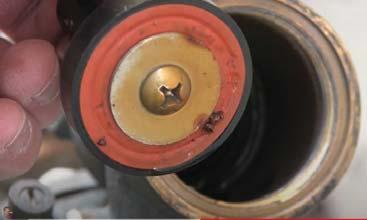
RP backflow devices with atmospheric ports are the ultimate CCC device. If they leak, they typically leak externally through the visible port. These devices offer The bonnet has cracked on a DCVA three levels of protection, causing it to leak. the third being the relief port on the bottom or side of the device. However, there is still a misconception that if a RP leaks occasionally out the port that means it is doing its job. Most likely there are pressure fluctuations downstream of the second check valve causing the port to relieve that pressure by purging itself. RP backflow devices offer three levels If the device is relieving of protection. constantly there is an internal problem with sediment or one of the checks. Typically, there is debris found on the first poppet or check, which usually deforms the rubber seal. If that’s the case and you don’t have a seal, you can flip the seal over and temporarily use its good side.


Tony Furst and Kazi Nasar are with Armstrong Fluid Technology.


THE RISKS OF SIZING PLUMBING SYSTEMS USING Hunter’s Hunter’s Curve Curve
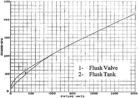
As plumbing professionals know, Hunter’s Curve is a common method of estimating the water demand of a building using statistical probabilities. For more than 70 years, the Hunter’s Curve method has been used to size plumbing systems, including booster packages, supply and drainage piping, and storage tanks. When Roy B. Hunter first created this basic method of measuring a plumbing fixture’s water flow in duration of flow and the probability that it would be in use, it was a very useful guideline (see Figure 1). Although its simplicity is still seductive, we now consider it to be a very conservative e e approach that significantly oversizes s plumbing systems and can lead to substantial increases in total cost of ownership. More importantly, it can also ls so o cause some potentially serious health concerns. c co onc cn er rns sn .
Figure 1 Current approach to sizing Water use will vary greatly depending on the building type, application and plumbing system sizing must take those factors into account.

THE LIMITATIONS OF HUNTER’S CURVE
1
2
1 - FLUSH VALVE 2 - FLUSH TANK Hunter’s original sizing concept was based on a large population for estimating demand, but the accuracy of the sizing curve diminishes as real-world populations are examined. When compared to other methods of sizing plumbing systems, such as IPC, UPC, IAMPO Water Demand Calculator, and so on, there can be huge discrepancies in estimated and actual results.
As seen in Figure 2 on page 54, Hunter’s (shown as existing) and the other sizing methods are almost always much higher than the actual measured results. In one instance, there is a difference of nearly 400 GPM versus less than 100 GPM.
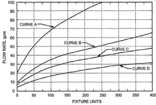
Modified Hunter’s Curve Method
Curve A - Restaurants Curve B - Hospitals, nursing homes, nurses’ residences, dormitories, hotels and motels Curve C - Apartment buildings Curve D - Office buildings, elementary and high schools
See us at CMPX, booth #1130

Estimated vs Measured Flowrate Comparison
74% reduction from what was calculated 74% reduction from existing 73% reduction from what was calculated
92% reduction from what was calculated Existing
Calculated Method 1
Calculated Method 2
Measured Note: Not all calculations were done at all sites
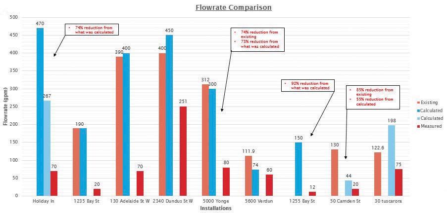
85% reduction from existing 55% reduction from calculated
Impact of using Hunter’s Curve: Biofilm
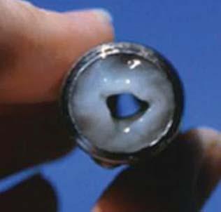
Unfortunately, there is an even greater problem with using Hunter’s Curve and that is the potential danger of harmful bacteria growing, and for contaminants to leach from the pipes into the water. Because this method often overestimates water demand, designers sometimes install oversized pipes. This can cause water to remain in the plumbing Velocity and turbulent flow minimize system for the formation of biofilms. longer than intended and/or circulate in the piping at lower velocities, allowing harmful bacteria to grow. Regardless of the type of water treatment the municipality and the building might use, there will be some degree of bacteria growth in your system. Domestic water systems that have low or no flow can develop bacteria blooms due to lack of chlorine and lack of fluid movement can result in biofilm coating the pipes. Not only does this biofilm create health risks, it also constrains the flow in the piping; increasing pressure drop and therefore energy costs. There can also be the issue of “dead legs,” which are defined as any area of the distribution piping system where water does not flow. These are prime areas for bacteria to blossom.
Increased costs as a result of oversizing
There are, of course, a number of other problems with oversizing plumbing systems, including the tendency to oversize the various system components. Oversizing booster pumps, for example, can add significant costs and require much more power to operate. Providing more power over a period of time can also dramatically increase electricity costs. Another costly consequence of oversizing is the larger footprint required to fit the larger equipment. In new buildings we have seen footprint reductions of more than 60 per cent, which save the building owners significant money. In retrofit situations it frees up valuable space to use for other purposes.
Alternative sizing methods
Now that we have a better understanding of some of the drawbacks of using Hunter’s Curve the obvious question is “what is the best alternative?” It should be noted that the IAPMO Water Demand Calculator is currently under review and we are advocating for the adoption of this new method. It’s currently only for residential, but we suggest using it as a guideline in combination with engineering judgement for use in other building types. However, none of the methods mentioned here are 100 per cent accurate and most of them still significantly oversize the system. In a recent survey conducted in conjunction with a webinar on this topic, we found that 43 per cent of participants still used the Hunter’s Curve or a derivation thereof. Another 35 per cent used IPC or UPC, 10 per cent used the IAPMO Water Demand Calculator and 12 per cent were self-developed based on experience. There are a variety of consulting engineering firms and manufacturers who can help you determine current or anticipated needs, measure existing flow (where applicable), and create a sizing system that can save you time, money and energy. However, there are two indispensable steps in the process that need to be followed:
are two types of flow – laminar flow (slow flow) and turbulent flow (fast flow). We also know that pressure loss in piping is related to the velocity of the flow and the friction loss along the pipe wall reduces the available pressure. The two most common equations for friction loss are Darcy-Weisbach and Hazen-Williams. We have found that the Darcy-Weisbach method provides the most accurate results.
2)The second step is factor in the following information: • Type of piping material • Supply pressure (inside the building) • Demand pressure • Flow rate (quantity) • Velocity limitation
Once you are armed with this information, you are now ready for booster and drawdown tank sizing. Booster pumps are arguably the single most important piece of equipment because they are responsible for increasing pressure and delivering fresh water to tenants and equipment alike throughout the entire building. Although more contentious, drawdown tanks can also be important in certain circumstances, especially in the following installation types: • Large buildings that have a large variance between peak flow, minimum flow and average flow. • Tall buildings where the pressure drop resulting from water demand will take some time to propagate down to the booster. • Older buildings or buildings more susceptible to leaks, which can erroneously be treated as if it was actual demand.
Sizing your specific plumbing system
You are now ready to size your system and determine design flow. Of course, your needs and demands can vary greatly depending on the type of building. For example, a hotel or office building will obviously have different water demands and usage patterns than a residential or university building. But regardless of the specific installation, there are certain factors to consider. Look for engineering partners who can offer proven experience in measuring water usage and designing customized solutions for buildings that are 100 per cent (or close to) occupied and don’t have variable occupancy levels; booster systems with advanced software solutions with advanced controls and analytics, including energy and water consumption data and profiling; and small mechanical footprints plus ease of installation and commissioning. By following these steps and working with the right partner you should be able to more accurately design your plumbing system while saving valuable time and energy.
Supply Drainage Support Specialties


The move towards mass timber buildings − Part I
Environmental construction approach is gaining momentum


Origine is a 13-storey residential project in Quebec City’s Pointe-auxLièvres ecodistrict. It consists of a 12-floor solid wood structure on a concrete podium and measures 40.9 metres in height.
Photos: Stephane Groleau
Buildings constructed of mass timber are becoming the “new kids on the block” for the residential and commercial sector. Mass timber architecture appeals to both builders and owners alike because of the ease of construction, large open spaces and high ceilings containing attractive wooden beams. Mass timbers are also more durable than typical wood products used in building construction according to experts in that field.
So, what is “mass timber” (or “heavy timber” as it’s called in the U.S.)? Significantly different from wood purchased at the local lumber store, mass timber is made from large pieces of wood either cut from a single log or made by laminating wood pieces together with glue or nails and screws. Types of mass timber include cross-laminated timber (CLT), glue-laminated timber (glulam) and nail-laminated timber (NLT). These timbers are then assembled during construction using custom joints and typically wooden pegs.
THE REGULATORY STOREY
Mass timber buildings are relatively new in Canada, dating back about 10 years. The first mass timber structures permitted under building codes were primarily one- and two-storey buildings. A significant change occurred in 2015 when the National Building Code of Canada (NBCC) increased the allowable number of storeys for mass timber buildings to six. In 2020, the NBCC moved the allowable limit to 12 storeys. British Columbia has been a leader in mass timber construction since it was first introduced. With a ready supply of timber and the desire to support the forestry industry, BC changed its provincial building code in 2019 to permit mass timber structures up to 12 storeys. BC Premier John Horgan stated at the time, “BC will be the first province in Canada to allow the construction of tall wood buildings up to 12 storeys, which means that we are ahead of the National Building Code.” Of the large provinces that have their own building codes, Alberta, British Columbia and Quebec have adopted the 12 storey provisions from the 2020 NBCC. Ontario’s current mass timber building code provisions remain at the six-storey level. Key regulatory concerns since the advent of mass timber construction are fire hazard and risk to public safety. Mass timber experts dispute these claims stating mass timber buildings are in fact fire resistant. One
online source explains “When exposed to fire, the outer layer chars and acts as a protective coating, insulating the wood underneath. Additionally, the lightweight nature of mass timber, weighing approximately one fifth of equivalent concrete buildings, allows for smaller foundations and seismic resistance.”
According to Horgan, “We’re not waiting for the rest of the country to get here. We already know that the product we are building or creating here is fire-resistant. We know that we can build faster and we know that it is better for the environment.”
With the right planning, 1,300 square metres of CLT can be installed per day, cutting construction schedules significantly. UBC’s Brock Commons tower rose 18-storeys in eight weeks.
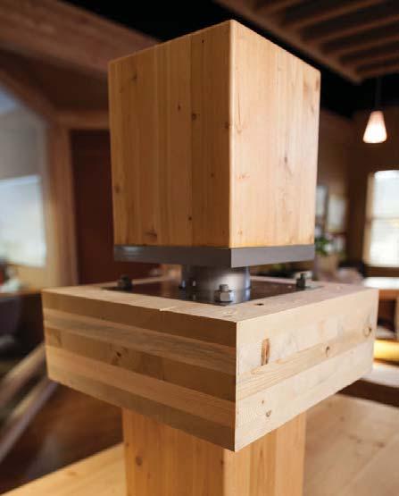
Photo: Forestry Innovation Investment
PROS AND CONS
Like all construction processes, there are advantages and disadvantages for mass timber. The most obvious advantage according to the industry is the unique look of the building where the timbers are left uncovered creating “a rustic look and feel that many people find welcoming.” Mass timber builders claim the construction process moves faster and fewer workers are needed on the jobsite. Construction involves large timbers that have been “cut to fit” specific parts of the structure and when brought to the jobsite, the timbers are simply joined together to construct the building. Some of the other advantages listed by the industry include: • structurally much stronger than standard buildings using
“dimensional lumber” such as two by fours, • additional floor space and open areas in the building because of fewer load-bearing walls, and • less wood being used by mass timber buildings as versus standard lumber buildings. Mass timber structures are also touted as “environmentally friendly” primarily because the timbers are a reusable resource and have a reuse life that can last as much as 100 years. Another environmental attribute is the CO2 large timbers can sequester within the wood. There is also less wood waste from the jobsite because of the “Lego-like” production of the timbers. These factors as well as the sustainable use of local wood for the timbers results in “a lower carbon footprint and lower cost to the environment.” Mass timber construction also has its challenges. One significant issue is the limited space for the mechanical services in the structure. While exposed timbers are aesthetically attractive, the trades have difficulty finding places to “hide” parts such as ductwork, wiring and piping. (Note: This will be covered in more detail in Part II of mass timber construction in an upcoming issue). Also, the simplicity of the construction process has to be weighed against the production time needed to precision cut the timbers and the heavy equipment needed on the jobsite to assemble the large timbers.
A significant issue with mass timber construction is the limited space for the mechanical services in the structure.

There are also two sides to the fire safety aspect of mass timber. The response to the claims of the mass timber industry appears to be the difference between fire “resistant” and fire “resistive.” Fire resistant products do not meet the Fire Code definition of fire resistive in that they still catch fire and must be extinguished. This distinction in the fire codes affects insurance and risk issues for mass timber buildings. Being a combustible product, mass timber is under significant scrutiny by underwriters at present, which leads to higher costs for insurance during and after completion of construction. These costs should decrease as more mass timber structures are built and more experience is gained with this type of construction. Effects from water exposure from severe weather conditions during and after construction such as warping, rot and mould are another risk. The industry is responding to this concern with solutions such as “tenting” of buildings during construction, a “glue topper” on exposed mass timber edges and decking, and moisture testing to determine the timber’s ability to dry out during construction.
Mass timber construction is relatively new in Canada. Realistically, this method is in its infancy and as industry experts suggest, many of the challenges facing mass timber need time and experience to determine solutions that will meet both building owner needs and insurance requirements. However, it is clear mass timber construction is here to stay and is growing in popularity as Canada considers the low carbon and GHG reduction targets the world needs in the future.


Be sure to look for Part II of “The move towards mass timber buildings” in an upcoming issue of Mechanical Business, which will cover HVAC and plumbing systems in mass timber buildings, and review key mass timber projects that have been or are being built in Canada.







JOBSITE JARGON
1) Damper
2) One Ton
3) Psychrometric
4) Reciprocating Compressor
5) EEV
6) Latent Heat
7) Watt
8) Package Unit
9) Inverter
10) TEV
11) Vacuum
12) EVI
Congratulations!
Match the terminology you hear in the field to the correct definition or function by April 14, 2022 and enter for your chance to win a Kane 599 wireless TRMS clamp meter. Send your answers tokerry.turner@mechanicalbusiness.com or enter online at mechanicalbusiness.com. In the event of a tie, the first entry in will be given the win, so don’t delay!
EXAMPLE:
Answer 1, K
ch
A) Space where the pressure is significantly below standard atmospheric pressure B) Controls the flow of refrigerant into a direct expansion evaporator C) A heating and cooling system contained in one outdoor unit D) Analysis of atmospheric conditions, particularly moisture in the air E) Device that creates a constant evaporator temperature by regulation of refrigerant flow through the system F) 12,000 BTUH G) Joule per second, can be used to express the rate of energy transformation with respect to time H) Energy released or absorbed, by a body or a thermodynamic system, during a constant-temperature process that creates a change of state I) Used in cooling systems to compress refrigerant by using a piston action J) Component that controls motor speed to increase system’s energy efficiency K) Opens and closes to regulate how much air flows through vents, or ducts L) Allows cold-climate heat pumps to improve performance in cold temperatures by allowing increased refrigerant flow into the evaporator coil
The winner of the Jobsite Jargon in the January/February 2022 issue is Sean Duffield. Duffield is a gas technician in Stouffville, ON.







REFRIGERANT RECOVERY: THREE TIPS FOR BETTER RESULTS!
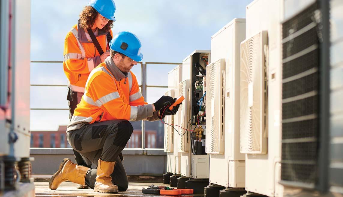
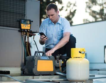
Refrigerant recovery is among the most common procedures done by service technicians, but best practices continue to change and evolve over time. This means continued learning and professional education are a must.
Where recovery once revolved around time-consuming methods and heavy, cumbersome equipment, updated techniques and new technology allow for more options, easier-to-use equipment and faster recovery times.
Being in-the-know about emergent tips and tricks within the field helps create greater levels of day-to-day professional efficiency and, since time is money, this translates to cost savings too. Implementing refrigerant recovery best practices allows experienced technicians and industry newcomers alike to optimize processes, prevent harm to themselves and premature equipment failure, finish the job more quickly, and ensure greater accuracy in the process.
1Emphasize refrigerant recovery safety With the ever-present concern that refrigerants could discharge at some point during a procedure, service technicians should be aware of pertinent regulations as well as the appropriate personal protective equipment that should be utilized when working with refrigerant, recovery machines and cylinders. Items such as protective gloves and shoes, as well as splashproof safety goggles or glasses, should always be worn. Specifically, provincial and federal refrigerant regulations mandate that refrigerant recovery be performed before opening any ACR system, whether for service or repair. This work must be conducted by a provincially- or federally-certified mechanic or technician, educated in the proper handling of refrigerant and adhering to established recovery practices. Whether in liquid or vapour form, refrigerants are considered highly harmful to the environment. As such, it is a violation of provincial and federal regulations to: • Fail to keep, or knowingly falsify, refrigerant records. • Fail to reach required evacuation rates prior to opening or disposing of appliances. • Knowingly release CFCs, HCFCs, or HFCs when repairing appliances. • Vent CFCs, HCFCs or HFCs.


When refrigeration or A/C systems are being replaced, undergoing repairs or being serviced, refrigerants have the potential to be released into the surrounding environment and eventually impact the ozone layer. Provincial and federal regulations allow for the safe handling of these harmful synthetic compounds by properly trained and certified professionals – allowing techs and HVAC/R companies to avoid costly government fines for violations while guaranteeing the safety of the environment and local communities they serve. More provincial and federal regulatory requirements to keep in mind include: • Do not vent refrigerants, as most cannot be legally vented. • Do not mix refrigerants in the recovery tank or in the system. • Recharging is generally OK. • Be sure to keep records of charge and recovery. In addition, using a recovery machine as required with each individual job, for example, ensures that refrigerant recovery is safely conducted, thus keeping refrigerant out of the environment. done effectively and with an advanced recovery machine, more removed vapour is then condensed into a liquid in the recovery cylinder. This option is typically slower than liquid recovery as higher pressures build within the recovery tank, and the tank may require cooling via either submersion in an ice bucket or by running cold water over the cylinder. • Push-pull refrigerant recovery refers to the method where the recovery unit effectively pulls vapour from the recovery cylinder, creating pressurized gas that then pushes the liquid from the entire system, ultimately returning it once again to the recovery cylinder. This process is slightly more complicated and should only be used for faster recovery on larger systems with more than 10 kilograms of refrigerant. For service technicians who know that a larger job requires more time, push-pull recovery is the best choice.
Understand recovery options
As trained service technicians know, refrigerant is consistently flowing throughout the line set of the HVAC/R equipment. As such, any time a technician encounters a leak in the system or must cut into the refrigerant circuit to remove or install 2 a new part, they must recover the refrigerant from the system first. Recovery is the process of safely transporting refrigerant from an HVAC/R system to a recovery cylinder. The speed at which this process is effectively and safely completed is of fundamental concern to the service technician. To completely recover all the refrigerant, there are three different methods most utilized in the field: liquid, vapour, and push-pull. • Liquid refrigerant recovery refers to the method where service technicians transfer refrigerant while it is in the liquid state. Refrigerant recovered in liquid form is by far the fastest method, but it has the potential to be problematic as it may cause liquid slugging at the recovery machine if the flow rate isn’t governed by a variable speed motor or a manual throttle. Likewise, depending on the specifications and circumstances of the job, this recovery method is not always possible, such as when outside ambient temperatures of approximately 21ºC or more cause refrigerant to vaporize. • Vapour refrigerant recovery refers to the method where refrigerant is removed while in a vapour state. Overall, the most time spent recovering refrigerant is in vapour form. When
The speed that refrigerant recovery is effectively and safely completed is of fundamental concern to the service technician.
Use the correct hoses and filters for optimal performance
Knowing the impact that hoses and Schrader valves have on the overall speed of any given recovery method is extremely important to the efficiency of the job. As a rule of thumb, using a hose thick in diameter and short in length results in faster rates of recovery. Utilizing short, larger diameter hoses lessens the restriction within the hose itself and provides a larger Implementing refrigerant recovery pathway for the refrigerant best practices allows experienced to travel through thereby technicians and industry newcomers creating a greater flow of alike to optimize processes. refrigerant recovered in far less time. Similarly, using valve core removal tools to remove the Schrader valves minimize restrictions and allow for even smoother flow of refrigerant. To simplify overall setup for any job, connecting the recovery machine directly to the system and throttling as necessary at the recovery machine speeds up set-up time, eliminates one more hose connection that would otherwise be required and means one less hose, one less step. It is recommended that service technicians use a filter dryer before the inlet port to ensure the continued protection of the recovery machine. The state of your filter dryer is telling of how bad the contaminants or physical filtration within the system may be. Through general use, these machines are likely to be exposed to external contaminants that impact the longevity and life of professional equipment. Keeping dirt, metallic slivers and other debris out of the machine, and making it a practice to swap out filter driers and screens regularly aids greatly to ensuring quality and reliable use.
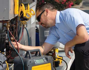
Tony Gonzalez is technical training manager at Fieldpiece Instruments, Inc., a manufacturer of professional-grade tools for the HVAC/R industry.
