6 minute read
REFRIGERATION Supermarket hot gas defrost systems
SUPERMARKET HOT GAS DEFROST SYSTEMS
Refrigeration systems in supermarkets and other large commercial-industrial applications frequently utilize several compressors connected in parallel. These parallel systems are often referred to as racks. The rack refrigeration system approach provides better capacity control when more compressors are used along with a VFD or with a compressor where all heads are unloadable.
Many evaporators are connected to the rack. The evaporators are grouped into several circuits and piped into the rack’s suction and discharge headers. Each circuit can operate at a different pressure so it is important that only the evaporators which will operate at the same evaporating temperature are grouped together.
The compressors are staged to maintain a pressure within the suction header that is low enough to allow flow through all the circuits. This means the suction header must be held at a pressure slightly lower than the lowest pressure circuit. To accomplish this, each circuit is equipped with an evaporator pressure regulator or EPR valve. The EPR valve is typically installed on the rack, but it could also be installed in a remote header. Some systems are set up this way so most of the solenoid valves and regulators can be separated from the rack and this often makes it easier to access and service these components.
Mechanical and electronic EPR valves are upstream or inlet regulators. With mechanical EPR valves, the spring pressure is increased by turning the adjustment stem in a clockwise direction. This results in the port closing somewhat and restricting the flow from the evaporators to the suction header. Electronic valves are typically driven by a stepper motor, which in turn is fed a series of electrical pulses to drive the motor in an opening or closing direction.
In addition to maintaining a minimum evaporating pressure, the EPR valve can serve as a suction stop valve. This is required during the reverse-cycle hot gas defrost cycle. The rack will also be equipped with a hot gas defrost header. Note that this defrost header is separate from the discharge header and supplies hot gas from a point that is after the oil separator.
Whenever the evaporator coil is cold enough to permit frost formation on its fins, the frost will reduce the capacity and efficiency of the evaporator. Frost build-up also restricts airflow through the evaporator.
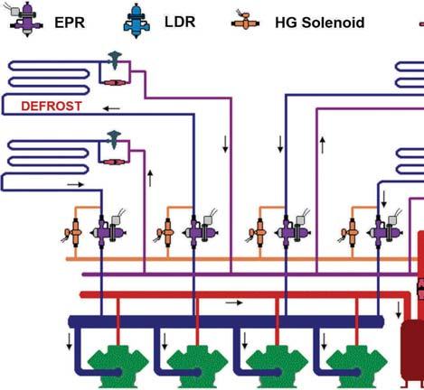
direction. Supermarket rack with EPR and DDR valves.

Electronic EPR EPR with suction stop feature
Phil Boudreau Phil provides sales and application support for Bitzer Canada Inc. and provides training and technical support for Bitzer’s clientele. He can be contacted at pboudreau@bitzer.ca.
The control system will initiate a defrost cycle a few times a day to clear the coils of frost and maintain maximum capacity, efficiency, and air flow. First, the liquid line solenoid to each evaporator is closed and then the EPR valve common to all evaporators connected to the circuit is driven closed. The EPR valve needs to be closed so the hot gas, when fed into the suction line, does not take the path of least resistance and travel to the suction header. Between the defrost header and the EPR valve inlet is a normally-closed solenoid valve. This solenoid is energized during defrost to permit hot gas flow from the defrost header to the suction line.
Hot gas will then flow into the suction line of the circuit toward the evaporator coil outlets. However, we closed the liquid line, so we somehow need to allow the liquid to return to the liquid header. To accomplish this, the expansion valve and liquid line solenoid valves will need to have a bypass line installed around them, such that the liquid produced in each evaporator during defrost can exit the coil and travel around the expansion valve and the liquid line solenoid. There are different approaches to this, but this is basically the way it works. The system needs to be equipped to address another challenge. How can we achieve reverse flow of hot gas from the suction line back to the liquid header, which is at a similar pressure to the hot gas? This is accomplished by installing a regulator that will produce a differential pressure during defrost. The idea here is to ensure that the discharge pressure is 20 to 30 psi or so above the pressure in the liquid header.

Supermarket system


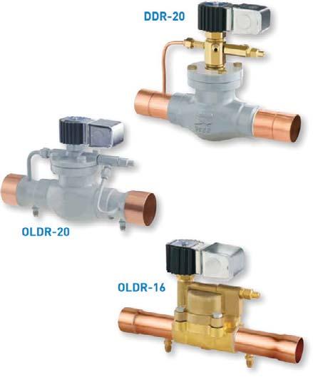
There are two main methods used to produce this differential pressure. The discharge differential regulator (DDR) is installed in the discharge line, between the rack’s oil separator and the condenser. Everything downstream from this regulator will operate at a pressure that is several psi below the compressor discharge header pressure. When the solenoid on this valve is energized, it will be fully open. If there are no circuits in defrost then it is less efficient to operate in differential mode, so we open the valve fully. When a circuit goes into defrost, liquid line solenoids in the circuit close, the EPR opens, the hot gas valve between the defrost header and the EPR inlet opens, and the DDR valve is de-energized so that it will hold a differential pressure. Note that this method will not work with the Hussmann Koolgas defrost method because the receiver will be at a pressure too low to feed desuperheated gas to the evaporator(s). With the Koolgas defrost approach, high pressure discharge vapour enters
the receiver, above the liquid where it is first desuperheated to some extent. This means that the receiver pressure needs to be high used to produce this enough to permit reverse flow through the arge differential evaporator(s) and back to the liquid header. the discharge arator and the Another option is to use a liquid differential eam regulator or LDR valve. The LDR valve e at a is energized when all circuits are in w refrigeration mode and de-energized when any of the circuits are defrosting. The LDR is also a differential regulator. However, the LDR is installed between the receiver outlet and the liquid header. This forces the discharge pressure and receiver pressure to some level above the liquid header pressure. A variant of the LDR valve is the OLDR n valve. The OLDR is basically the same as goes into defrost, the LDR valve except the OLDR valve is uit close, the de-energized for full-open operation and etween the energized during differential mode. Note that et opens, and either an LDR or OLDR or similar type of so that it will regulating valve must be used on systems that employ the Koolgas defrost approach. Note for this example, we have looked at the Sporlan/Parker DDR, LDR and OLDR. However, any regulator that can operate in both full-open and differential pressure modes can be used.

Differential regulators


Sustainability is not about off-grid or by the many.


Make Oxford Energy’s OLPP™ solar kit the


