53 minute read
CIMAC data vision


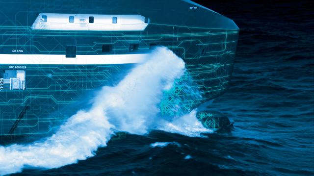
DIGITALISATION: LINES OF COMMUNICATION
Digitalisation promises to be nothing short of transformative for shipping, but at the same time many of its multifaceted challenges are particular to the industry - and require breaking new ground
Let’s start with the obvious. “Data is valuable,” says Eero Lehtovaara of ABB Marine & Ports. Gone is the utopian idea that it should be freely available.
And that can make for a tussle about who gets to do what. Taking a single example, one supplier “refused to allow their data to be used on our engine performance monitoring platform”, relates Carmelo Cartalemi of WinGD. In a fairly classic case of cart-before-horse, he says they were “more interested in putting our data on their system”. Although that was equitably resolved, the current situation has given rise to “ambitious” OEMs, he says, “which can make collaboration a little challenging, each wanting to protect their data and sell their own solution”.
Further, while it’s possible to take lessons from other industries, shipping involves a far higher number of stakeholders and manufacturers says Jonas Åkerman of Wärtsilä: “There are about as many platforms as there are OEMs.” The result is a complicated and uncoordinated view of the onboard equipment.
Against this backdrop, Lehtovaara is leading a newly launched initiative by CIMAC which the organisation describes as ‘consolidating the vision’ on the digitalisation of power and propulsion. As he explains, “at present, although standardisation is high on the agenda, currently there is very little in the way of integrating modern onboard technology”.
It does have an impact: “At the moment we are building engine rooms and bridges that are unnecessarily complex because we’re trying to extract data from proprietary systems and interfaces,” he says.
This leads to duplication of processes and inconsistencies in the presented information. Lehtovaara admits “we have clients and crew becoming irritated about getting a variety of responses depending on which way they ask a question of the shipboard systems”.
As a result, Dmitry Kisil of WestP&I, who’s experience comes from a technical superintendent role as well as a ‘hands on’ user, adds: “If you ask a ship’s master or chief engineer, do you want the latest digital version or a crowbar, he’ll usually say, ‘the crowbar’.”
It’s not that surprising. As Stam Achillas of ABB Turbocharging says, “as an industry we are still in the early stages of digitalisation”, adding the real value of these solutions “comes when companies can access data ‘beyond’ their own equipment, enhancing their diagnostics and advisory capabilities together with partners”. Collaboration is, therefore “a necessity”.
Much has already changed: take the “broad acceptance of condition-based monitoring and predictive maintenance”, says Åkerman. As a result, rather than merely dealing in lumps of steel, the big engine manufacturers have, as MAN ES points out, moved “towards a service and solutions offering based on measurable and manageable performance”.
But from that arises the question about who holds the keys. Certainly, many believe a common ecosystem is necessary, and a lot of OEMs have rushed to provide one.
However, Åkerman’s colleague, Frank Velthuis, adds that there’s been a recent wake-up call: “We now have no illusion that ours will be THE platform that gets everyone onboard,” he admits. Instead, he says, “more and more fleet owners say they want to have control over the data themselves”. And that is sorting out the old nugget of who owns the information: ship owners are increasingly clear they do.
So OEMs are generally turning their attention round to making their packages work on other people’s systems. It requires “some complex work on the interfaces,” says Cartelemi: “Of course, we believe ours should be the standard, but then, so do all the others.”
At the same time, there are pitfalls: fleet owners’ new ‘doit-yourself’ approach can lead into expensive blind alleys: “no-one needs parallel developments in a 100 different companies”, says Velthuis. The answer, he believes, is to buy in more general services, like CBM, and save the budget for specialised or unique systems. And then, be focused: “Think first about what it is that you want to achieve, and how you are going to do that,” he advises: “Start with the end in mind - and take a staged approach: make sure you really do have the value there before you pursue it.”
However, third-party cloud platforms may be able to offer a different type of solution.
For example, Houlder, (which is about to enter the market) aims to liberate ship operation, raising efficiency “without a lock-in to a specific vendor”, says Arun Pillai.
To be clear, it’s not just about remote diagnostics. While a remote overview is valuable - and decentralised data analysis from shore may indeed be the long-term future - Houlder’s platform can also act as the glue between separate shipboard elements, explains Pillai’s colleague, David Hugh. By direct application of nicely cooked and sliced information it could, for example, refine the response between engine and CP propellers or other systems. That is a significant step in itself.
But the possibilities reach even further: Pillai adds that platforms like these promise to redefine how onboard power is utilised by helping rationalise and smooth out peak loads, raising efficiency and lowering both OPEX and CAPEX.
8 Effi ciency requires
integrating systems from multiple suppliers
While developments may tie onboard systems together, could they further segment the industry?
Andrea Lazzaro of WinGD has studied what’s happened in other sectors, such as aerospace. Here, “a standardized protocol (ACARS) was originally established some years ago to send mainly safety-related packages of information via VHF radio, and later via satellite”, he explains. However, “more recently, with the huge increase in information bandwidth and computing power, various players have developed more complex proprietary data exchange systems”.
So the technology has evolved from a shared system, to something much smarter - but at the cost of standardisation. “Everyone wants to present a cleverer data interface with better, richer diagnostics,” says Lazzaro.
With so many data platforms available and so many shipowners developing their own solutions, “being able to integrate systems from multiple suppliers is crucial for the successful digital transformation of the industry” says Achillas. As such, manufacturers like ABB Turbocharging invest in developing APIs for integration into a range of platforms. “It is a lot more work,” says Achillas, “but flexibility is key.”
Like others, MAN ES sees the answer in “a combination of core in-house capabilities and co-operation”, working hand in hand. But there’s reason to believe an industry ecosystem should not be a commercial operation. Despite the company’s role as the mýa platform’s initial founder, the idea is to draw in others to create an independent, open-to-all, collaborative space. Essentially, agreed standards and a common, metadata architecture will integrate all the OEM data streams, enabling a complete system view, but most importantly, it allows different parties to work together on optimisation programmes, secure that data will only be shared by permission.
However, looking beyond all this, Åkerman says the next challenge lies in “integrating data from cloud platform to cloud platform”. He adds “it’s still a bit Wild West”, but interoperability pressures mean “cloud platforms are converging at an increasing rate”.
This itself may rescue CIMAC’s vision: even self-interested parties will eventually recognise that, as Achillas says, “the true value of data is only discovered when it’s translated into meaningful information”... and that means “getting less protective - an open approach to sharing raw data would enable more powerful analysis to add further value for the shipowner”.
ON EDGE
There is an issue: data transfer is limited at sea.
Therefore onboard - edge - computing has to crunch the incoming information, filtering out spikes and outliers (and quarantining them) to get at the very limited points to be sent home, as well as extracting what’s needed for local shipboard applications. But it’s essential that nothing’s lost: Cartelemi explains WinGD’s information is made available in both “in the raw” as well as in a filtered, readable version for onboard applications.
Edge and cloud may therefore have to operate separately for extended periods, only falling back in step with each other when there’s a reliable (and cyber secure) data transfer link. So before signing up, owners will have to dig into exactly how hefty a load these applications could put onto shipboard computers.
While not so much an issue for new builds, “the problems lies with the existing fleet,” says Achillas. “While these ships may be generating useful propulsion control data, they lack the infrastructure to harness this data.” He adds: “Tapping into that could be done, but it would require some initial investment. Owners have to assess whether the potential improvements in vessel efficiency are worth it.”

VALIDATION
Information accuracy is, itself, is a tricky subject: “Who is responsible for the validation of the data, especially if it’s critical for the operation of other onboard machinery?” asks Lehtovaara. For example, “if my trim-adjusting technology gets the wrong numbers on engine thrust, the trim will be out, raising the ship’s fuel consumption”.
“You now need shipping-wide standards for data validation,” says Kisil. Despite the competition, some, like Cartalemi, firmly believe the natural ‘home’ for these large systems is the class societies. It would lend itself to an efficient crossover “for example, accepting a maintenance extension based on data validated by an independent, trusted party”, he says.
It is, however, a hot topic that’s bound to run and run.
AUTOMATION
All this inevitably touches on the broader subject of automation.
Companies such as Kongsberg, Wärtsilä and ABB are currently working to raise levels of data exchange between onboard components. In fact, Lehtovaara believes that “many future developments will talk system-to-system”, though not all: some elements will need to be checked by the bridge. He says: “It’s not a matter of getting rid of the crew, but co-existence needs to be more effective.”
It requires consideration, especially as digitalised onboard technologies will likely track each other more and more closely, so “a simple advisory won’t always be the best way to handle anomalies”, says Kisil. Moreover, he adds that given the amount of data-sharing between systems , transparent mapping is necessary. Further, he adds, “a loss of input should be immediately identified, allowing everyone to see which system is feeding into what, and where it’s gone wrong”.
It’s clear that the future isn’t taking digitalisation on a ‘component by component’ basis, but will require “seeing the whole ship as a system” says Lehtovaara. It promises to be a long road. Despite “yards and other organisations investing a lot in supporting this discussion... it’s a gargantuan task”, he concludes.
One thing that everyone agrees on is that the way forward has to be collaborative. As MAN ES concludes, “digitalization is often reduced to a purely technical level... In fact, it is above all a cultural issue: a mindset”.
8 While it’s possible
to take lessons from other industries, shipping involves a far higher number of stakeholders and manufacturers
FUSING DATA TO PROVIDE ACTIONABLE INSIGHTS
Kashif Mahmood, Senior Vice President of Digital Solutions at American Bureau of Shipping, discusses how ABS’s new digital platform will help shipowners to optimise operations
Kashif Mahmood discussed the specifi c advantages of ABS’s new digital platform, My Digital Fleet™, for ship owners and operators in an interview with The Motorship in October. In a wide-ranging interview, Mahmood touched on the challenges of developing algorithms for operational machinery, before concluding with potential wider applications of the solution’s digital architecture to remote fl eet operating centres.
The underlying philosophy behind the My Digital Fleet solution is that the increasing disparity of data means that the data itself will become a source of competitive advantage for ship owners and ship operators. Mahmood suggested that current discussions within the industry about the ultimate ownership of data were missing the point: the ability to combine data elements rapidly together was itself a source of competitive advantage.
At its simplest, My Digital Fleet is a data platform that permits ship owners and operators to access relevant operational and Class data for their assets. The solution’s real-time, data-driven insights are intended to improve fleet efficiency, reduce costs and help manage risks.
The solution combines (or ‘fuses’) data from discrete feeds from ABS’s proprietary structural, machinery, and environmental analytics products with third-party data covering emissions, compliance, cyber security and weather conditions to provide an integrated picture of the risks and operational condition of an asset. This platform allows an asset’s performance to be viewed in terms of regulatory compliance, fuel efficiency, structural and mechanical integrity.
However, the platform is designed to be modifiable in order to respond to an individual ship operator’s or ship owner’s requirements.
MY DIGITAL FLEET
Mahmood stressed one of the key advantages of the My Digital Fleet solution is its flexibility and adjustability. As it is built around a component-based design, different elements can be turned on or off, while ship owners or operators also partnerships into the system.
This flexibility means that the solution is compatible with the different operational and commercial requirements of small and medium-sized operators as well as larger fleets.
He added that the solution had been trialled by several large-scale ship operators, as well as smaller-sized ship owners. As the data can be viewed at an asset and aggregate fleet level, it could be useful for ship owners seeking a composite view of all their assets where their vessels are managed by several ship managers, for instance.
ADOPTING AN AI MBL APPROACH
In 2019, Mahmood and ABS decided to completely rearchitect how it produced analytics, implementing smart components that automatically internally adjust to the data feed instead of developing vessel-specific models. “We adopted hardcore cognitive AI,” Mahmood said.
The data from different combinations of sensors are fed into the central digital asset framework, or “central database”, which then allocates it to different templates depending on the volume of data.
“Rather than going out and retrofitting equipment to algorithms to make them effective like everyone else, we are retrofitting the algorithms to the equipment to bring time to value.”
The digital asset framework applies machine-based have the flexibility to integrate their own data feeds and data
learning to extract valuable insights from the raw data, allowing significant data elements to be identified while “screening out the noise”. Meanwhile, similar models look at data supplied from other critical systems, such as gensets, turbochargers, ballast water systems and so on.


ADVANTAGES OF FRAMEWORK
The AI/MBL approach also offers significant flexibility going forward.
“I can now propagate the model according to any business metric that you want to look at,” Mahmood said, adding that development work was focusing on environmental emissions, as this was a key area of focus for shipping.
Looking forward, Mahmood expects My Digital Fleet to expects My Digital Fleet to eventually play a more active role in assisting le in assisting operational decision making, based on the sed on the expectation that remote operating centres g centres will play an increasingly important role tant role supporting crews in the future.
“We have architected My Digital Fleet tal Fleet to run in a remote operating centre, and in re, and in fact, it runs in our own decision support n support centre,” Mahmood notes.
8 ABS’s new
digital platform, My Digital Fleet, currently runs in ABS’s own decision support centre
8 Kashif Mahmood,
Senior Vice President of Digital Solutions at American Bureau of Shipping
MAN TARGETS FIELD TESTS FOR OXICAT METHANE SLIP TECH
MAN Energy Solutions anticipates a 2025 market launch for one of its key technologies for eliminating methane slip from four-stroke gas-burning dual-fuel engines
The other, switching the engines from the Otto to the Diesel combustion principle, will be validated in conjunction with the use of future fuels such as methanol and ammonia.
On-going improvements in engine design have enabled MAN to reduce methane slip by around 50% since it first introduced four-stroke dual-fuel engines to market in the mid-2000s. The development of new methane oxidation catalysts (oxicats) is anticipated to reduce this even further, to 70%. A first, fundamental research project on possible catalyst technologies finished in September 2020, says Dr. Gunnar Stiesch, Senior Vice President, Head of Engineering Engines at MAN, speaking exclusively to The Motorship. This fundamental research included development of sulphurresistant oxicats which he says hold great promise for dualfuel operations.
The research has been undertaken as part of the “IMOKAT” project which received financial support from the German Federal Ministry for Economic Affairs and Energy. The project has already achieved a methane slip reduction of 70% on both spark-ignited (SI) and dual-fuel engines using synthetic exhaust gas under laboratory conditions.
Oxicats are not an option for two-stroke engines due to the lower exhaust gas temperatures associated with these engines. All oxicats today need high temperatures of more than 500°C to promote methane reduction, says Stiesch. Therefore, the oxicat delivery system must be positioned before the turbocharger on four-stroke engines. “Temperature control is critical to ensure performance,” he says. “Methane-reduction performance will decrease rapidly once the desired temperatures can no longer be met. Therefore, engine controls need to be thoroughly adapted to ensure the necessary boundary conditions for the oxicat.”
Stiesch revealed the future project timeline where this will be addressed: “We will investigate catalyst-engine interaction between 2021 and 2023. This also includes the installation of a field test system on board a vessel. We think that the technology could be ready for market launch by 2025.”
Concurrently with this research, MAN is working to reduce methane slip by over 90% with the introduction of the direct gas injection technology already used on ME-GI two-stroke engines to its four-stroke dual-fuel engine range. This change from Otto to Diesel combustion will be tested and validated in conjunction with future fuels such as methanol and ammonia. MAN’s engineers are already assessing the feasibility of direct gas injection on four-stroke gas engines and will be able to apply the technology when the market demands it.
In the Otto combustion process, gaseous fuel is pre-mixed with air before ignition. The mixture is compressed and ignited by a spark plug or liquid pilot fuel and is thus in the cylinder for all of the induction and compression strokes and for part of the power stroke. Four strokes rely heavily on gas exchange at the inlet and exhaust valves in the Otto process, so there is increased opportunity for the gaseous fuel to evade combustion, leading to methane slip.
Converting to the Diesel combustion principle means that, as with ME-GI two-stroke dual-fuel engines, the gaseous fuel will be injected with the diesel pilot into the compressed charge-air at around top dead centre. This will prevent methane from escaping during the four-stroke cylinder scavenging process.
Smaller fuel injectors need to be developed to suit fourstroke engine sizes, and because of size restrictions and higher rpm, a four-stroke application will in general need a somewhat higher injection pressure than a two-stroke application, says Stiesch. This necessitates the installation of compressors that allow for acceptable injection duration at rated power. The additional cost of this equipment is offset by the lower fuel consumption achieved and hence lower CO2 emissions attainable with Diesel dual-fuel combustion.
Currently, MAN’s four-stroke 48/60 and 51/60 engines can be retrofitted to run on LNG. MAN’s on-going research goals anticipate that synthetic, carbon-neutral fuels will pave the way for a future of climate-neutral shipping. Meeting the 2050 goals set by the IMO will mean large parts of the existing global fleet will need to be retrofitted from liquid fuel to dualfuel liquid/gas operation.
MAN sees LNG as the first step in preparing engines for the broader use of a range of synthetic fuels, and a dual-fuel engine brings the option of using synthetic natural gas either as a drop-in fuel or a total fuel solution as it becomes available. An addition to the business case for retrofitting engines to be dual-fuel is the potential for significant performance upgrades as a result of more modern engine technology and the addition of the latest electronic controls. This, says Stiesch, makes dual-fuel operation a future-proof investment.
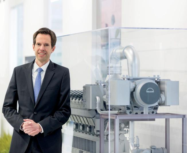
8 Dr. Gunnar
Stiesch, Senior Vice President, Head of Engineering Engines at MAN
AMMONIA RELEASE STUDIES REVEAL HAZID ANALYSIS NEED
The development of rules and regulations for the safe use of ammonia as ship fuel will take time and will need to be developed on the back of a solid program of research and development
Much of this research has already begun, says Ed Fort, Global Head of Engineering Systems at Lloyd’s Register (LR). In the meantime, LR will be publishing guidance on conducting HAZID studies to support the use of hydrogen and ammonia as fuels. The organisation is also working with MAN Energy Systems on HAZID studies for its ammonia engine currently under development.
Fort notes similarities with LNG: Both hydrogen and ammonia, like natural gas, are low flashpoint fuels existing as gases under ambient conditions, and as such, they were prohibited for use as a ship fuel by SOLAS regulations until relatively recently. However, it must be noted that due to the characteristics of hydrogen and ammonia, increased and additional safety hazards need to be addressed compared to natural gas.
Ammonia is a highly toxic gas under ambient conditions, and exposure to even relatively low concentrations in air can be harmful, potentially fatal, compared to natural gas which is generally considered non-toxic, says Fort. Exposure to ammonia at concentrations of 2,500 ppm or 0.25 percent in air can result in fatalities after 15 minutes, while exposure to ammonia at concentrations of 5,000 ppm or 0.5 percent in air can be fatal within just a few minutes.
“While it is recognised that ammonia has been widely and safely used as a refrigerant within the confines of ships for many years, such refrigeration systems are typically sealed or closed loop systems, and as such the likelihood of an ammonia release within the confines of the ship are expected to be significantly lower compared with its use as a ship fuel,” says Fort.

8 Olav Hansen is a leading authority on the use of hydrogen
and ammonia
Hydrogen and ammonia, like natural gas, will generally be compressed and/or liquefied for onboard storage. The boiling point of ammonia is -33.4ºC, and it is typically stored as a liquid either refrigerated or pressurised at ambient temperature.
In Hydrogen and Ammonia Infrastructure Safety and Risk Information and Guidance, a report for the Ocean Hyway Cluster released in May this year, Lloyd’s Register noted key differences between the hazards of liquified and pressurised ammonia. Author Olav Roald Hansen, now founder of HYEX Safety, highlights that a release of pressurised liquid ammonia would likely form a denser than air, very cold, mist cloud, and modelling suggests more severe consequences than for a release of refrigerated liquified ammonia, LNG or liquid hydrogen.
If ammonia is stored at room temperature at around 10 bar over-pressure, a leak would be pushed by a much higher vapour pressure than refrigerated ammonia which would leak by gravity. Around eight percent of the liquid ammonia released at pressure would immediately evaporate on leaving the tank, its rapid expansion would also crush the remaining liquid ammonia into a denser than air aerosol fog. The ammonia fog in air would be cooled to the saturation temperature of the liquid at the reduced pressure (down towards -70ºC) and evaporate when further diluted in air. In this case, if escaping due to emergency venting, the released ammonia plume may fall down to deck or the sea at dangerous concentrations.
In contrast, if ammonia is stored at its boiling point, there will not be spontaneous boiling when it leaves containment. Leak rates would be moderate, a pool will be formed, and evaporation would mainly be due to heat from the floor. Rate will be limited and can be controlled by design, says

8 Ed Fort, Head
of Engineering Systems at Lloyd’s Register
Hansen. In an engineroom setting, the ammonia could evaporate leading to potentially dangerous concentrations, but this can be contained relatively easily and when ventilated to a gas mast the ammonia vapour will be buoyant and seek to go upwards.
“If you consider a refrigerated release in an engineroom, you would smell it immediately, and you would have some time,” says Hansen. “If you get out and close the door, it should be possible to make the situation safe. If you compare it to other flammable fuels, ammonia is only moderately flammable (concentrations above 17 percent are required compared to five percent for natural gas), so it is not necessarily as big a challenge to fight an ammonia fire. For other fuels, such as LNG and hydrogen, it is quite dangerous to be in the room when it releases as flame exposure may be fatal.”
Due to its high heat of vaporisation and strong expansion when boiling hydraulic shocks may be a concern for ammonia. A land-based accident in the US releasing 14 tons ammonia was caused by cold liquid ammonia being injected into pipes containing warm gaseous ammonia. This led to fast condensation and pressure drop which broke the pipes. In a bunkering context, there is a potential risk of hydraulic shock if residual ammonia is left in piping systems.
Experience with ammonia in selective catalytic reduction (SCR) systems has led to the use of double-walled pipes to minimise the risk of leaks. MAN Energy Systems notes that the fuel pipes on its ammonia engine currently under development will be doublewalled, with the outer pipe preventing escape to machinery spaces in case of a rupture of the inner pipe. A ventilation system with the capacity for 30 air changes per hour vents any gas in the space, including around valves and flanges.
Ammonia is highly corrosive to a range of materials including zinc, copper, plastic and brass when it is mixed with water. Stainless steel and iron are relatively immune within normal operational temperature ranges. In developing its ammonia combustion engine, MAN Energy Systems has therefore, for example, determined that sealing rings will be made with Teflon.
Currently there are no detailed technical requirements prescribed in rules and regulations for the use of hydrogen and ammonia as fuel onboard ships. Detailed regulations will take several years to develop, but there is still time if prioritised by the IMO, says Fort. “Until such time as technical requirements are prescribed in the rules and regulations, the use of hydrogen and ammonia will be permitted on the basis of a satisfactory engineering analysis, essentially a risk assessment, carried out on a case by case, ship by ship basis.”
Risk assessments for new fuels are becoming more commonplace but still present challenges during ship construction, says Fort, so it is vital that all stakeholders fully recognise the importance of a thorough, rigorous process and recognise the associated impact on resources, schedule and costs. “It should be recognised that the use of hydrogen and ammonia as marine fuels is not business as usual. The potential prize of zero emission vessels is huge, but it will come at a significant cost to the industry which needs to be recognised and accounted for at the outset.”
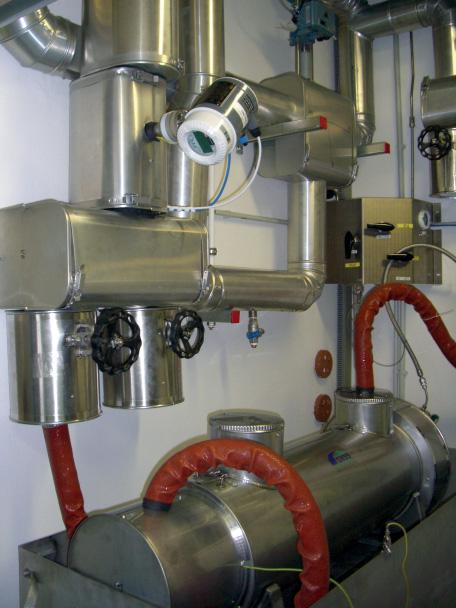
A RELIABLE SOLUTION FOR BUNKERING OPERATIONS
ENSURING A SIMPLE AND RELIABLE TRANSFER OF LNG.
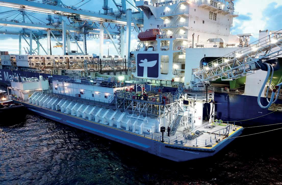
The increasing demand for LNG as a fuel goes handin-hand with developing the supply chain. With an LNG experience of over 55 years, GTT offers solutions for bunker ships within every kind of navigational areas (inland waters, coastal, seagoing, shallow draft).
In 2020, GTT celebrated the 100th bunkering operation of the Clean Jacksonville LNG barge. To achieve a high level of flexibility in cargo transfer operations, the barge features the innovative REACH4 TM bunker mast, developed by GTT.
The Clean Jacksonvillebarge is able to transfer, in a reliable way, enough LNG for two round trips of the TOTE Marlin Class container vessels. This operation lasts less than 6.5 hours while cargo operations are conducted in parallel.
Providing solutions to facilitate the transition to LNG as a marine fuel; GTT.
Technology for a Sustainable World
Learn more on www.gtt.fr
HYDROGEN STORAGE AND COMPRESSION ADVANCES
The storage and compression of hydrogen using metal hydrides is advancing in the automotive industry, and the technology holds promise for marine applications
Metal hydride hydrogen storage systems, where hydrogen atoms are absorbed into the interstitial spaces of a metal compound, were established in mobile applications early this century with the construction of the German Type 212 and Italian Todaro class diesel-electric submarines. Built by Thyssen Krupp Marine Systems, the submarines feature an air-independent propulsion system based on Siemens proton exchange membrane (PEM) compressed hydrogen fuel cells. Similar storage systems to those used for the submarines have also been used on autonomous underwater vehicles.
More recently, automotive use of hydrogen fuel cells has expanded with the introduction of vehicles such as the Toyota Mirai. Research has increasingly focused on the potential benefits of a metal hydride compressor capable of delivering pressures up to 1,000 bar for rapidly refuelling these vehicles, and it is technology that could also make rapid refuelling practical for vessels such as fuel-cell powered ferries.
Different metal hydrides are used for different applications. For example, Professor Craig Buckley of Curtin University in Australia is working on the usage of metal hydrides for thermal energy storage. The metal hydrides suitable for this application would have as high as possible reaction enthalpy (meaning they should release as much heat as possible when reacting with the hydrogen and should absorb as much heat as possible when releasing the hydrogen).
This is the opposite of what is desirable for hydrogen storage and compression. Nonetheless, heat is released during uptake of hydrogen into a metal hydride-based storage tank, and it has to be cooled if the hydrogen charging is rapid. Heat is required when the stored hydrogen is to be used and therefore released from the storage tank.
Some metal hydrides can release their stored hydrogen using the heat available in seawater (at temperatures ranging from 0-20°C). Others need heat at higher temperatures and can use the waste heat of a PEM fuel cell. Yet others need even higher temperatures which can be provided if the hydrogen is used in a high temperature fuel cell or burned in an internal combustion engine.
Hydrogen has the highest energy density per unit mass of any fuel, but its low volumetric density at ambient temperature and pressure means it has a low energy density per unit volume. Metal hydrides are a desirable storage medium, as they are the most compact and dense hydrogen
storage possibility, says Dr. Martin Dornheim, Head of the Department of Nanotechnology, Materials Technology, at research institute Helmholtz-Zentrum Geesthacht in Germany. “Hydrogen is absorbed or sponged up by the solid material and thereby stored much denser than is the case for high pressure gas storage (700 bar) or liquified hydrogen at -252°C. It can store the hydrogen at low pressures (tens of bars) and ambient temperature.”
METAL HYDRIDE FOR ONBOARD STORAGE
Dornheim and his team are exploring applications for stationary hydrogen storage, the delivery of hydrogen shoreside as well as for onboard storage of hydrogen on ships, and he says the compact storage offered by metal hydrides means that a tank design can be fitted into any space available in a ship.
Storage tanks that use conventional metal hydrides have a key disadvantage, though, compared to 700 bar hydrogen gas storage or liquid hydrogen storage, says Dornheim. They weigh up to four times more than compressed gas storage tanks using type III and especially type IV tank shells (these are low or no metal containing cylinders which are stabilised for example by carbon nanofibers).
To overcome this issue, he is working on novel light metal hydrides and hydride composites with a storage capacity per weight for hydrogen which is more than five times higher than conventional metal hydrides. One light candidate is a sodium-aluminum-hydrogen compound. “However, this specific light candidate has only three times the weight capacity compared to classical conventional hydrides,” says Dornheim. “More promising are composites / mixtures of different light metal hydrides and borohydrides and amides.”
There are a large number of different metal hydrides currently being investigated, and they vary depending on the
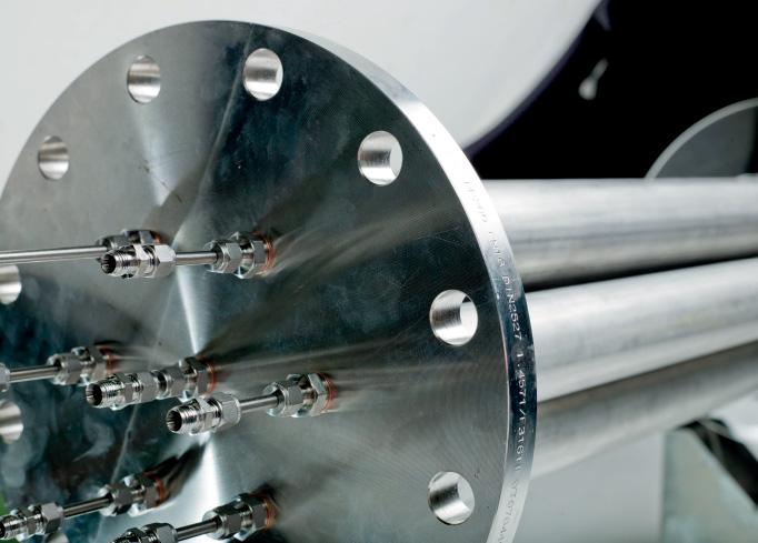
8 Hydrogen storage
tank based on a lightweight metal hydride (SodiumAluminium-hydrogen compound)
application, including the compression of hydrogen from low pressures to very high pressures for uses such as automotive refuelling. “This compression is possible just by using the physics of metal hydrides,” explains Dornheim. “They can be filled with hydrogen at rather low pressures and low temperatures. If the temperature is raised, however, the hydride wants to release the hydrogen again. The higher the temperature, the higher the hydrogen release pressure. This is a basic thermodynamic principle, since at high temperatures all systems want to go into the state where entropy is highest.”
COMPRESSOR ADVANTAGES
Metal hydride compressors can deliver very pure hydrogen. This can be difficult to achieve with mechanical compressors which can suffer hydrogen purity issues as a result of the lubrication and abrasion of the piston. Ionic compressors are another option. They have fewer moving parts than mechanical compressors and have been used to deliver hydrogen at pressures up to 700 bar. However, metal hydride compressors offer the advantage of having no moving parts, because they use thermal energy rather than mechanical energy. This means they operate silently and require no maintenance.
Hydrogen compressors are usually stationary systems, so their weight is not as important as their compression efficiency: with as small a temperature difference as possible, the hydrogen should be compressed as much as possible. Furthermore, hydrogen compressors should ideally have an ambient operating temperature for hydrogen uptake and temperatures below 100°C for the release of the hydrogen, says Dornheim. If the hydrogen is to be compressed to very high pressures like 800 bar, metal hydrides with a rather low stability (low bonding or reaction heat) are required.
Burckhardt Compression and GRZ Technologies in Switzerland are developing hydrogen compression technology that uses thermally active metal hydrides. The Static Hydrogen Compressor from Burckhardt Compression is based on GRZ Technologies’ HYCO laboratory compressor that is already in use for small amounts of hydrogen. Without moving parts, it is noise and vibration free and is hermetically sealed from the environment. This means it can operate without any gas leakage and can be used in sensitive areas.
Scaled-up, the technology will be designed for high-pressure applications of 200, 350 and 700 bar. As well as its refuelling potential, the technology can store renewably produced electricity, supply peak power for an extended period of several months and be used as a backup power supply.
Dornheim is also collaborating with GRZ Technologies along with the Ecole polytechnique fédérale de Lausanne (EPFL) research institute in Switzerland as part of the International Energy Agency Hydrogen Technology Collaboration Program - Task 40 “Energy Storage and Conversion based on Hydrogen.” Over the next few years, the researchers aim to develop reversible or regenerative hydrogen storage materials and systems suitable for mobile, stationary and portable applications, electrochemical storage and solar thermal heat storage. This will involve furthering the fundamental understanding of hydrogen storage chemistry. For example, the effect of catalysts is not yet well understood in complex or liquid hydrides even though catalysts are important for hydrogenation/dehydrogenation processes.
Dornheim’s team is also collaborating on a number of other projects including the EU project “Hydride4Mobility” which aims to improve metal hydride-based hydrogen storage tanks for mobile applications and for metal hydridebased compressors. The project partners are addressing critical commercialisation issues for hydrogen powered utility vehicles using metal hydride hydrogen storage and
Image: HZG
PEM fuel cells, together with the systems needed for their refuelling at industrial facilities. A first test case will be a forklift.
For this type of application, metal hydrides with a high specific weight are an advantage, as the unit can then function as a vehicle counterbalance without any extra cost. However, the slow hydrogen charge and discharge of these metal hydride systems, the complexity of their design and the efficiency of system integration remain challenges to overcome.
Dornheim is also collaborating with Volkswagen, plant apparatus developer Panco and tank experts Stühff, on the design and construction of a hydrogen storage system for a fuel cell car as part of the German funded “H2HybridTank” project. Under the framework of the European HyCARE project, he is also developing a stationary hydrogen storage system for the storage of 50kg of hydrogen, around 10 times more than that stored in a fuel cell car.
A key challenge for mobile applications in the future is the reduction of hydrogen refuelling pressures and shortening of refuelling time. Research suggests that the properties of metal hydrides in higher pressure applications may not behave the same as they do in low pressure systems, and at high pressures, degradation over multiple cycles could occur. Apart from optimising the composition of the hydrides, another challenge will be to reduce the cost of manufacturing them.
For hydrogen compressors, the challenges include minimising void space to reduce losses of productivity at high pressure, effective heat exchange between the metal hydride and the heating/cooling fluid, minimising the heat lost during periodic heating/cooling of the metal hydride and hydrogen gas containment at operating pressures over 500 bar.
The metal hydrides being developed for hydrogen compression are expected to be similar to the ones for hydrogen storage. Ideally, they should have well-matched operating pressure and temperature ranges, high reversible hydrogen sorption capacities, fast kinetics, minimal volume decrease upon dehydrogenation and high cycle stability.
8 Hydrogen
storage tank in test apparatus where it is loaded and unloaded with hydrogen and in parallel cooled or heated by a heat transfer medium
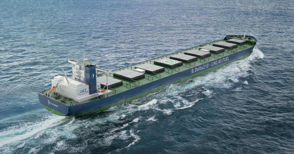
DUAL-FUEL CAPESIZE DESIGN MAINTAINS HOLD CAPACITY
Deltamarin and GTT’s LNG-fuelled Newcastlemax design has the same cargo capacity and dimensions as a standard 210,000dwt Newcastlemax but can carry enough LNG for two round trips from Australia to China or one round trip from Brazil to China
Classifi cation society ABS granted Approval in Principle (AIP) for the design late last year, and the companies are now in discussion with leading mining companies and Newcastlemax shipowners. But the design is not limited to the iron ore market. Chin Lim, Product Line Manager for bulk carriers at GTT, says the vessel design is fl exible enough for a range of trades and vessel sizes from Capesize to Very Large Ore Carriers, carrying not only iron ore but also coal or grain.
With the support of GTT, Deltamarin studied various arrangements for the LNG tank, until the AIP was granted for the tank located in the aft of the 50-metre wide vessel, behind the accommodation. By locating the tank here, it has no impact on available cargo space or the vessel’s hull dimensions and is clear of any hazards associated with cargo loading and unloading.
Any changes to a conventional Newcastlemax design were kept to a minimum with the result that the introduction of the LNG tank, larger in dimension than the equivalent heavy fuel oil (HFO) tank it replaces, only required the relocation of the vessel’s gensets and engine casing.
The design is compatible with both high and low pressure two-stroke main engines from MAN Energy Systems and WinGD. Due to its high efficiency and lower methane slip, the MAN 6G70ME-GI (16 MW) engine with exhaust gas recycling was selected as base case for the design. The fixed pitch propeller, rudder bulb and stator fins have been chosen to maximise propulsion efficiency. Electricity is generated by three dual-fuel auxiliary gensets, and heat is produced by a dual-fuel boiler.
As part of the vessel design process, the hull shape was optimised using the latest digital tools developed by Deltamarin. One, Deltaseas, was used to evaluate sea states on the selected routes, and the main engine can be optimised for the actual operation of individual vessels, reducing fuel consumption and emissions.
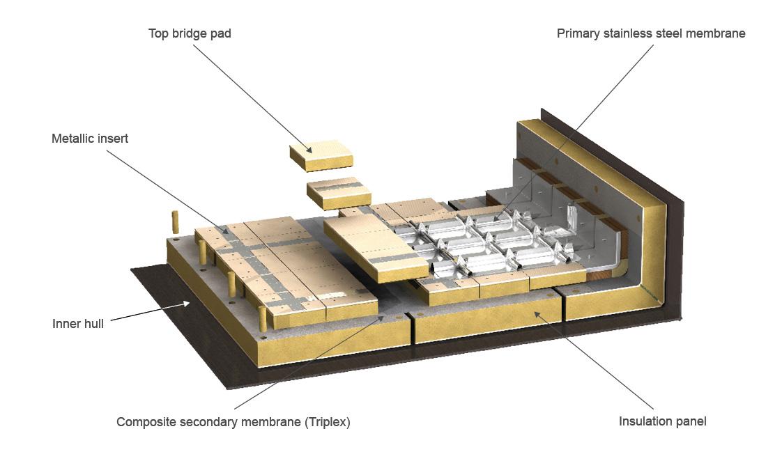
The designs incorporate GTT membrane-type LNG tanks with the LNG bunker fuel stored at atmospheric pressure. For vessels on the Australia to China trade, this tank will be approximately 5,500cbm for two round trips; for the Brazil to China trade, it will be approximately 7,500cbm.
This tank capacity would not have been possible if Type C technology were used, says Lim. GTT membrane tanks are more compact and have a useful volume 10-15% greater than Type C tanks, and this was enough to enable the larger capacity required for the Brazil to China trade. The tank, partially located below the main deck, can be increased in height to provide even greater fuel carrying capacity. The use of a single tank means that only one gas handling system is required, also saving space, complexity and expense compared to a Type C solution, says Lim.
The Mark III tank is directly supported by the ship’s hull structure, and the thickness used for the Newcastlemax design balanced cost and boil off rate, resulted in a relatively light tank that has reduced impact on the ship’s fuel consumption. There cannot be any filling level restriction in a bunker tank, and the potential for sloshing was taken into account when shaping the tank. The resulting design underwent over a year of testing and sloshing simulation covering the whole range of North Atlantic sea states.
Maintaining a low operational pressure makes gas venting unlikely and facilitates faster bunkering with fewer bunkering
8 LNG-fuelled
Newcastlemax with Mark III membrane tank
personnel required. The design allows for bunkering from either side of the vessel by ship or barge. With current global infrastructure, it is anticipated that the Newcastlemax vessels will bunker at Singapore for both the Australia to China and Brazil to China trades. Singapore would also be conveniently located for seaborne metallurgical and thermal coal routes between Australia and South and East Asian destinations.
Another consideration is idle time, which is relatively high for typical Newcastlemax operations, i.e. up to several weeks. If the propulsion system is not using the boil off gas (BOG), pressure and temperature in the tank could increase, but GTT and Deltamarin have optimised the tank shape and insulation properties so that a reliquefaction plant is not required. The system has been designed so the natural boil off can power hotel loads, such as in port stays or at anchorage, through BOG compressors. When sailing, a vaporiser-pump is used to supply fuel to the power and propulsion systems.
The optimised hull and overall design with LNG propulsion provides fuel savings up to 35% and CO2 reduction up to 57% compared to previous ship design with VLSFO for the Australian iron ore trade. Deltamarin’s calculations show that the vessel design is approximately 10% below the baseline of EEDI Phase 3.
Currently, Newcastlemax vessels cost around $50-55 million to build. The price including an LNG fuel system is less than $65-70 million, says Lim. The specific payback time for the LNG system varies depending on the trade, and Lim refers to a SEA-LNG study published earlier this year on a 210,000dwt ore carrier sailing from Australia to China. The study illustrates strong returns on investment for LNG as a marine fuel on a Net Present Value (NPV) basis over a conservative 10-year horizon. The modelling analysis is bolstered by compelling payback periods of two to four years for a newbuild Capesize on this major iron ore trade corridor.
The SEA-LNG study is part of a series of studies which also cover a 14,000 TEU container vessel operating on the AsiaUS West Coast liner route, a dual study examining an 8,000 CEU Pure Car and Truck Carrier (PCTC) on the Pacific and smaller 6,500 CEU vessel on the Atlantic Trade Lanes and a 300K DWT VLCC sailing from the Arabian Gulf to Asia.
Membrane tank volumes can vary from 1,000cbm for passenger ships, to 10,000cbm for tankers, and close to 20,000cbm for very large container vessels, such as the Jacques Saadé-class 23,000TEU vessels operated by the CMA CGM Group. With an 18,600cbm LNG tank, these ships are the largest container ships in the world to use LNG as fuel.
Deltamarin’s references include various vessels with LNG bunkering capabilities, and the company says GTT’s technology is particularly suitable for greater range or larger ships. In close cooperation with GTT, Deltamarin has therefore created a unique portfolio of cargo and passenger vessels that save valuable cargo space compared to classic cylindrical tanks and enable the use of LNG for long ocean voyages.
The designs include a 2,300 TEU container feeder concept and a 8,000 CEU PCTC. The modularised GTT membrane tank solution employed can be adjusted in size from 1,000 to 5,000cbm, depending on the case vessel. Either one or multiple tanks can be integrated into the vessel, with the final fuel capacity being a trade-off between cargo capacity and bunkering intervals. The solutions are all scalable.
8 GTT’s Mark III
membrane tank technology
8 Chin Lim, Product
Line Manager for bulk carriers at GTT

Credit: GTT
PREPARING FOR A TRANSFORMED MARKET: WINGD’S SCHNEITER
Dominik Schneiter, Vice President of R&D at WinGD discusses the challenges and opportunities of developing solutions for upcoming transformations in the shipping market
QFrom an engine design and operation perspective, what do you think have been the most important
technological innovations during your career?
AJust talking about engine technology, we have seen many changes, from electronic controlled common rail engines through to the introduction of Tier 1 and Tier 2 regulations on emissions. [The Motorship notes that Sulzer RT-Flex engines were the first to incorporate use electronic controlled common rail systems for fuel injection and valve actuation in 2000].
We have also managed a number of changes of fuel, such as the reduction of sulphur limits to 3.5%, and recently down to 0.5%. Regulation also led us to make the engine more efficient, with higher power densities and peak pressures.
Digitalisation itself is nothing new. Its just another name for what we used to call alarm and monitoring systems and case-based maintenance systems in the ships. Unmanned machinery was already being developed in the 1970s. But it is true that our ability to connect systems has changed radically in recent years. While we have been most affected by the integration of the power system onboard the ship, we have also seen a transformation with the ability to integrate data from other sources, such as route planning, weather planning, cargo planning and so on.

QAs a mechanical engineer by training, how do you see the future role of the internal combustion engine? Will it
remain the main mover for marine transportation in the future?
AThe short answer is that, as long as we need high power output to move large deep-sea vessels, two-stroke low-speed engines will remain the work horse of marine transportation. However, unless we want to install nuclear power plants, no viable alternative exists at the moment. And unfortunately public opinion just isn’t ready for nuclear plants aboard ships right now.
But the way that we design a vessel’s propulsion system is likely to continue to evolve. We may see a reduction in the size of gensets, and there is even a chance that we may see smaller energy sources being replaced by renewable energy sources in some instances. The main change is that we will see much more system integration. By situating the twostroke main mover at the heart of a much more integrated network of energy producers and consumers, it will be possible to combine PTO and PTI solutions with an electrical grid. In fact, we have recently started quoting to a few select customers for a first commercial installation where we would act as system integrator handling the energy management system, combining an X-DF engine with PTI/PTO and an energy storage system.
I’m positive that the internal combustion engine will remain at the heart of vessel propulsion for a long time to come.
QHow is WinGD responding to the challenges of developing energy effi cient solutions in response to
IMO decarbonisation goals?
ADespite political pressures from outside the industry, we are seeing players in the industry who have set very ambitious targets who want to go further than the IMO initial roadmap. This is triggering investments on the technology side, from both private and institutional sources. We will soon
8 Dominik
Schneiter, Vice President Research and Development at WinGD
see the introduction of viable technical solutions that can be applied on board, some of which are currently being partially tested on board. These would just prove the concept that large vessels can be operated on a carbon neutral basis.
QWe have heard many diff erent perspectives on potential zero carbon fuels. What is your perspective
about the current debate about alternative fuels?
AAs I just mentioned, we are making progress in developing solutions to help shipping meet or exceed current IMO targets. The main challenge is around the fuel: whatever fuel we opt for needs to be available in the volumes needed for the market.
The obvious solution would be hydrogen or another hydrogen-derivate (such as ammonia), but we expect other industries will pay a premium to access these high-quality fuels first. I would expect that shipping will process waste products from synthetic sources or bio fuels, such as biomethane. So, we will be working with a mix of fuels, which will require our solutions to be equally flexible, technologically.
Fortunately, our X-DF concept has the capability to burn all of the fuels being discussed. From a technological perspective, we are confident that we can handle all of the fuels being discussed.
The key challenge is more of a political one, which is to ensure the fuels are available at fair prices. I think more work is required on that side of things.
QOnly one alternative fuel has been successfully introduced commercially into the market. Looking at
the current market for LNG-fuelled vessels, how do you see the technology and the market evolving?
AIf you look at alternative fuels that are currently widely available, and becoming more available, LNG is the only viable alternative to low sulphur fuels at present. DNV GL also identified LNG as the main transition fuel until 2050 in its latest Alternative Fuels report. The fuel has a number of other advantages: crews are familiar with using LNG as a fuel, and the necessary regulations are in place. The IGF Code exists.
Finally, there is another major advantage for LNG compared with other fuels. Public attention has largely gases, and has moved away from the toxic emissions. But I expect public attention to switch back towards the local impact of NOx, SOx and PM emissions. The EU is already pushing in that direction.
Finally, LNG can be easily blended with either LBG or synthetic liquefied natural gas, which are more sustainable than fossil energy.
Looking forward, we are working on concepts to convert an X-DF engine in order to make it compatible with alternatives like methanol, looking at the fuel supply system and other shipboard systems. Converting an LNG-fuelled X-DF engine to operate on alternative fuels will be easier than if you have a traditional HFO engine and just want to run it on a new fuel.
QYou have recently announced the launch of the fi rst of a series of effi ciency improvements for the X-DF2.0. Tell us about the iCER, and how far you think methane slip A can be reduced? iCER is the first new technology introduced as part of X-DF2.0. With the extensive experience we have in our lowpressure dual-fuel X-DF engine portfolio, we recognized the potential for further optimisation. This year we introduced iCER – Intelligent Control by Exhaust Recycling. iCER, based
on an EGR concept, delivers enhanced combustion control by cooling and recirculating part of the exhaust gas through a low-pressure path during operation in gas mode. The result is a reduction in methane slip emissions of up to 50% when using LNG and a significant reduction of fuel consumption, of 3% in gas mode and 5% in diesel mode. focused on the global warming potential of greenhouse
QDo you see further possibilities for further advances in LNG engine effi ciency? A The Otto cycle technology is still pretty new for low speed two stroke engines, and further development steps can be expected. While the X-DF2.0 development, which largely addressed methane slip efficiencies was the main one, there will be more. The technology’s admission of the fuel mixtures into the part stroke is unique. We are confident that we can improve on the fuel efficiency in future. And of course, the ability to switch between diesel and gaseous fuels offers certainty in terms of future asset value. The technology combines a high degree of flexibility with a rather low cost and simple system.
QWhat is your perspective on regional developments, such as extending the Emissions Trading System to
shipping?
AWe think regulations are helpful and can prompt technological developments. But we would prefer global standards to be agreed, so we only need to develop one set of solutions to comply with them. This has been the case with NECA areas in North America and Europe, for example, where we could develop one solution.
Similarly, a Carbon Levy could be a powerful tool, if you used the money generated from a levy for technological development funds. That could be an interesting way of developing new technologies. The Norwegians have demonstrated the benefits of this approach for decades. But it would create difficulties for us as technology developers if Europe introduced a different model to the United States, for example.
QFinally, looking ahead, are there any other solutions that we can expect to see added to the portfolio over
the next few months?
AWe expect to complete the roll out of our new engine control system by the middle of next year. This was first introduced on the X92-DF and we will have switched over our X82-DF by December.
8 WinGD has
begun quoting for a fi rst commercial installation where it would act as system integrator handling the energy management system, combining an X-DF engine with PTI/PTO and an energy storage system
INNOVATIVE DESIGNS FEATURE NEW GEOMETRY HULL FORMS
Naval architect fi rm NaviForm provided details of its new geometry hulls, including the power savings expected based on tank testing of the unprecedented designs
Vancouver-based NaviForm has designed a ROPAX that has the upper RORO deck extending all the way to the bow, a river container ship with external hull support that boosts container-carrying capacity and a Detachable Stern Vessel (DSV) that doesn’t suff er from the fuel penalties of a traditional Articulated Tug Barge (ATB). The concepts, with vessels built and in various stages of construction under ABS class, also feature a number of new design features to reduce fuel consumption.
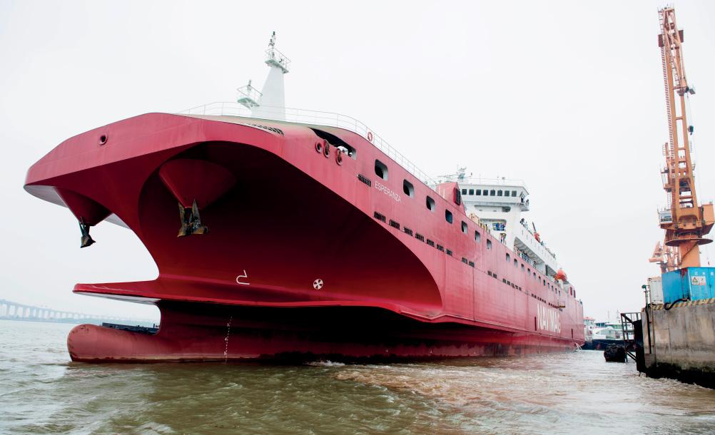
The first of two ROPAX, MV Esperanza, entered oceangoing service in Chile for Navimag Ferries this year. She features a new winged bow that reduces hull resistance, resulting in either higher speed, or less power usage, fuel consumption and GHG emissions. It also reduces motion in waves, shown in testing and in operation to be 50% lower than conventional bows, and eliminates slamming, therefore making it possible to design a lighter hull structure.
The winged bow reduces power requirements, because it splits the hull into a slender form below the wings, and a very spacious form above it. The wings cut into waves and are shaped to produce inverted vertical force that prevents the bow from raising over the wave and then crashing into the next one. This has been proven in several separate model test programs spanning 20 years of research.
The design works best for the low weight / high volume payloads typically found it passenger, RORO or military vessels. At 10,500 ton, the 150-metre long Esperanza needs only 2,500kW to sail at 14 knots, while having 1,800 lanemetre capacity on only two decks, without any articulated
Credit: NaviForm
internal ramps. It is the first time an upper RORO deck extends all the way to the bow at full width. “ABS had to verify that it is not prohibited by any regulations. It is not. Nobody simply thought of it before,” said a spokesman for NaviForm.
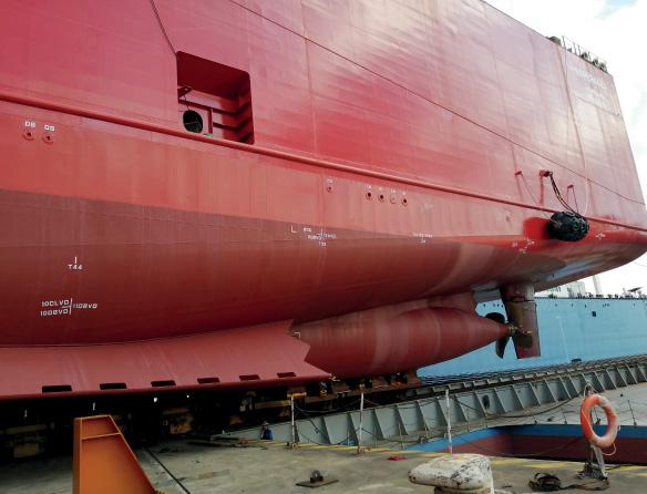
The vessel features another NaviForm innovation, new geometry stern bulbs that spin the flow of water into the propellers counter to their rotation. The design has been model tested at the National Research Council Canada towing tank in 2006 and shown to increase propeller efficiency by approximately 10%. NaviForm explains the results: “The higher the coefficient affecting propeller efficiency “w”, the higher the propeller efficiency. The typical value for this type of vessel is 0.15; it can go as high as 0.22. We discovered this new hydrodynamic phenomenon on our 15-metre model, for which the model basin measured w of 0.43. They kept re-checking it, as it was unheard of.”
The bulbs were actually designed for a different reason: to house the large engines and to keep the shafts short, a well known feature in many twin shaft ships. This new geometric feature led to extensive research of optimising stern bulb form to maximise propeller efficiency.
According to towing tank tests conducted at SVA Potsdam in Germany, the bow design results in a reduction in power needs of close to 20% compared to the next best hull of that size. However, she required a learning curve in operation, as the winged bow performs best in a narrow range of forward draught.
Esperanza is powered by two Wärtsilä 9L20DF engines each directly driving a Contracted and Loaded Tip (CLT)
8 The dual-fuel
RoPax Esperanza was delivered to Chile-based ship operator Navimag in March
propeller via a Wärtsilä gearbox. The gearbox is connected to a 800 kW PTO/PTI motor which in good weather feeds excess power to support hotel load. In bad weather, the vessel’s service generators will take over that load, and in severe weather one of the gensets will supply an extra 800kW power into propellers.
Esperanza has an Energy Efficiency Design Index (EEDI) that meets present and future IMO targets without the need to reduce speed. Overall, fuel savings are claimed to be around 20%, with the bow and the stern bulbs contributing roughly half each. These numbers are being confirmed in operation. Esperanza sails on weekly schedule from Puerto Montt to Puerto Natales, in the port of Punta Arenas, Chile. Most of the route is in the Patagonia inside passage, narrow and twisting, followed by around 80-100 nautical miles in the open ocean where weather can be severe.
A sister ship of Esperanza is expected to be contracted shortly.
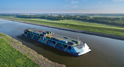
EXOSKELETON BOOSTS CONTAINER CARRYING CAPACITY NaviForm has also designed a series of river-going container vessels with novel features. An external structure dubbed the Exoskeleton fits outside the hull to provide longitudinal strength rather than relying on the strength of the hull structure. This allows ocean-going and river hulls to be lighter and in the case of river hulls, also extremely shallow.
The vessels, currently being tendered to US shipyards by owner American Patriot Holdings, also feature a zero wave bow that eliminates the problem of shore erosion for river vessels and barges. Featuring two side skegs with a foil between them, it captures the flow and directs it under the hull, rather than to the side.
The vessels are designed for service on the Mississippi. Construction of the first hull is due to begin in Q1 2021, with three sister ships to follow at six monthly intervals. The 181 metre x 30 metre hulls have 2.7 metres draught. The hull depth is only 3.9 metres and steel weight only 2,300mt, around 40% less than vessels of a similar size. NaviForm says that for a river vessel of this size, the hull depth would typically be a minimum of eight metres, possibly more. This depth difference frees up space for 1.5 tiers of containers. The vessels will carry an unprecedented 1,700 TEU at speeds up to 16 knots, although the owner anticipates that when slowed by the traffic these LNG-fuelled vessels will only use half of their installed power.
ABS has issued an Approval in Principle certificate for the design, but there are very few existing rules that apply. “The concept is so new that rules simply don’t exist yet to address its components,” said Naviform’s spokesman. “For example, there are no rules addressing the Exoskeleton, so ABS had to review the design based on finite element analysis, as first of a kind.”
Credit: NaviForm
8 Construction of the fi rst of a series of four river-going
container vessels for operation on the Mississippi River is due to begin in Q1 2021
The vessels’ 11.5MB diesel-electric system will feature Voith Schneider propellers forward and aft. They will have two LNG Type C tanks with a total capacity of 1,000cbm located in the middle of the hull, between the generators, to minimise trim.
DSV EXPECTED TO OUTPERFORM ATBS AND MONOHULLS NaviForm says its patented DSV offers the same benefits as an ATB but without the speed and power penalties. The ATB concept was developed in Europe in the early 1960s as a cost saving approach to short voyage trade: instead of three vessels with three engine rooms and three sets of crew, one tug would push a barge, leave it at a terminal where the second barge was unloaded and loaded, bring the second barge home, where the third barge was unloaded and loaded.
Today, this technology is best known in US where the tug and the barge are seldom separated. “While improvements have been made, it is still a barge, not as efficient as ocean going ships, and a tug that inserts its bow in a notch in the barge’s stern,” says the NaviForm spokesman. “The current performance penalty is estimated at around 12% more power and fuel consumption than a similar deadweight single hull ship.”
NaviForm reversed the approach. Instead of designing a barge and a tug and connecting them, NaviForm designed an efficient hull, then cut out the stern out of it. “When merged, it is hard to see where the one ends and the other begins. The stern (or the tug) bow does not resemble a conventional bow, but rather a double cone on a horizontal axis. This shape allows the stern to rotate inside the hull’s stern notch when it pitches in waves. The performance penalty is eliminated.”
While ATBs are known for their tugs pitching excessively in the notch, the DSV solves that problem by moving the connecting pin location close to the stern’s (tug’s) Longitudinal Center of Floatation.
When connected, the DSV is essentially a single hull, and when combined with the energy efficiency design features of the other vessel designs, it is expected to outperform conventional monohulls.
NaviForm’s designs are protected by patents in the US, EU and several other countries, four have already been granted, another three are pending. A trademark has been secured for the abbreviation DSV.
8 The Esperanza


