21 minute read
Intrinsically safe smart devices have an important role to play in improving productivity and employee safety


PROCESS CONTROL
Operation-driven matrix design
Advertisement
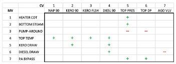
A multivariable control matrix has manipulated variables (MVs) on one axis, controlled variables (CVs) on the other axis, and models in the matrix that indicate a relationship between that MV/CV pair. Effective multivariable controllers use the right models for various control and optimiSation needs. Allan Kern reports.
Matrix design practice refers based on more basic control and large-matrix practices. It differs to how control engineers operation improvements, but which from optimisation-driven design in go about designing do not necessarily justify the high cost key ways. It often results in smaller the matrix at the heart threshold of the large-matrix paradigm. multivariable controllers, rather of any multivariable controller. A In conventional multivariable control than one large controller, with multivariable control matrix consists of technology, the built-in optimizer always fewer variables and models. When manipulated variables (MVs) along one has been considered an essential piece, concerns arise regarding a variable’s axis, controlled variables (CVs) along so most involved never questioned it. importance, its efficacy for control, or the other axis, and models at various Instead, the search has looked for better the reliability of its models, it is often locations within the matrix, which ways to support and maintain the largeleft out of the matrix. Leaving it out indicate a relationship between that MV/ matrix controllers. However, with insight errs on the side of reliability. Keeping
CV pair (Figure 1). Designing the matrix from decades of experience, it is now it errs on the side of optimisation. consists of selecting the MVs, CVs and possible to see alternative ways to build The overarching goal of operationmodels which, for various control and smaller and more efficient multivariable driven matrix design is automation, optimization purposes, are wanted in control applications to address not optimisation, and such a design the multivariable controller. operation and control needs without a strives to include only necessary,
‘Large-matrix’ design practice has built-in optimiser, and therefore without reliable, and worthwhile parts. been dominant in industrial applications the side-effect of growing the matrix In operation-driven matrix design, for the last 30 years. beyond its basic control and operation groups of related single-loop
In large-matrix practice, a widescope. controllers are identified, based on ranging plant test is used to identify all frequent (often highly coincident) related process variables and process Operation-driven changes to setpoints, outputs or interactions (models). An underlying matrix design modes. This activity represents principle has been more variables and Operation-driven matrix design manual open-loop multivariable more models yield a more complete can reveal important automation control being carried out by the solution, for both control and for opportunities that have previously operating team. The objectives are optimization purposes. It has been remained ‘below the radar’ of to: routine for large-matrix practice to result in one large multivariable controller spanning an entire plant unit, with dozens of variables (sometimes more than 100) and hundreds of models (sometimes upwards of 1,000).
A side-effect of this approach is that most installed multivariable controllers in the process industry today are large, complex, fragile, costly, and challenging to own, operate and maintain.
Moreover, the large-matrix approach has Figure 1: Multivariable control matrix for an atmospheric crude distillation column, based on excluded smaller multivariable control operation-driven design practice. The matrix is smaller than traditional crude column applications. It addresses primarily column pressure and product inferential quality control, which are often the applications that may be warranted most valuable objectives of this application – and often the ones found ‘unclamped’ in existing large-matrix applications. Images courtesy: APC Performance LLC
PROCESS CONTROL
1. Automate these manual multivariable control scenarios to capture the well-known intrinsic benefits of closed-loop versus open-loop control. 2. Relieve the operating team of repetitive control loop micromanagement, thereby allowing more time to play a proactive process oversight role.
Operation-driven design does not strive to include all related variables and models. It often focuses on the ones already used in existing manual multivariable control operating practices and procedures. It automates established proven procedures and captures the experience and skill of the operating team regarding which MVs are suitable and reliable for controlling which CVs. Using automation to capture operator skills is an important criteria that largematrix practice often neglects in favour of greater optimisation.
What about optimisation?
Optimisation belongs in the business layer, based on access to site-wide information, ability to bring a variety of planning, scheduling, blending and modelling tools to bear, and the appropriate execution time frame, which is typically daily and not in real time. Common practice is performing daily updates to the (optimised) sitewide production plan and handing it down via the operating chain of command, usually starting with the ‘morning meeting’.
This raises questions about the conventional multivariable control built-in optimiser in the control layer. In the control layer, multivariable control needs to execute at high frequency because process values are subject to real-time changes. However, optimisation normally does not need to execute at high frequency because optimization normally does not change in real time. This makes the control layer optimiser redundant and
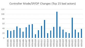
Figure 2: Operation-driven multivariable control application ‘low altitude radar’ spotlights potential multivariable control applications that have remained ‘below the radar’ of large-matrix practice. Like previous industry-wide initiatives to address loops-in-manual and bad-actor alarms, this simple technique identifies multivariable open loops that can be closed to capture the well-known benefits of closed-loop vs. open-loop control and operation.
unnecessary, even as it contributes significantly to the high cost and maintenance of conventional multivariable control applications (second only to model maintenance).
Low altitude radar
Many smaller multivariable control applications have remained ‘below the radar’ of the large-matrix multivariable control paradigm, but the exact nature of these applications and a method to identify them has never been proposed – until now. A simple technique for spotting these applications is to use a console activity log to reveal the controllers that require the most operator intervention in the form of setpoint, output or mode changes (Figure 2).
A safe assumption is most of these bad actors are effectively in a manual multivariable control scenario, wherein operators must frequently adjust groups of related controllers to keep related process variables within constraint limits and (to the extent possible) at optimum target values. [Note: the term ‘optimum target values’ refers to how remaining MV availability (after constraint control) is utilised, and does not necessarily mean the value comes from a real-time optimiser, which in fact it often does not.]
This manual open-loop activity can be automated — these multivariable loops can be closed – by deploying an operation-driven multivariable controller to capture closed-loop control benefits versus open-loop control.
This same technique has successfully been used in industrial applications twice in recent memory: Once to address loops-in-manual (as opposed to multivariable loops in manual) and once to address bad actor alarms.
In each case, this technique was used to show the extent of the problem, and then measure progress towards best practice target metric values. According to EEMUA 191, Alarm systems — a guide to design, management and procurement, operators should not have more than one alarm per 10 minutes. However, there is no best practice guideline for controller interventions per hour. This also has remained below the radar — until now. !
Allan Kern, P.E., is owner, president, and control engineering consultant at APC Performance LLC.
HAZARDOUS AREAS
Enhancing safety with mobile solutions
The goal of enterprise mobility solutions is to network people, plants and systems, using data as efficiently as possible. The use of intrinsically safe smart devices can help improve productivity and the safety of employees, says Dietmaer Deppisch.
The flood of data coming from modern production facilities is usually managed by central controls. However, for comprehensive and timely monitoring of processes, data needs to be available closer to the process and more directly – preferably in real time and with low latency. Modern, intrinsically safe (IS) smartphones and tablets can serve as decentralised mini data centers or digital gateways – for example in combination with professional software, sensors, beacons or other smart peripheral devices. The accumulated data can be transferred to the mobile device in real time and evaluated there, with the corresponding applications, at any location and at any time. This solution can help improve productivity and also significantly raises employee safety in hazardous areas.
The right safety level
Employees frequently work alone on the plant floor, outside the range of hearing and vision of their colleagues. They can be exposed to higher risks in their daily work and depend on quick assistance in case of an emergency. If no appropriate safety precautions are taken, injuries, accidents and consequential damage to people and equipment can easily occur. The company must ensure that an accident is detected and the rescue chain is set in motion swiftly. In case of critical hazards it is mandatory to set up a certified lone-worker protection solution (LWP).
Programmable 3D motion sensors can automatically trigger an alarm in the event of a hazard, report the exact location of the incident and
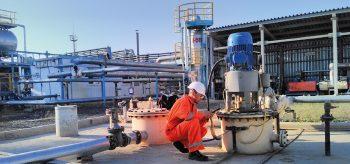
By working alone in hazardous areas workers are at higher risks of an accident so need better protection.
document the entire process for later investigation.
A typical comprehensive lone worker protection system will consist of Personal Alarm Signal Terminals (PAST) just as a mobile phone or wireless device; Personal Alarm Signal System (PASS) (software on server); and connection between the PASS and PAST via telephone or wireless network. For larger scale lone worker protection solutions mobile devices can be integrated into cloud server systems. The Pepperl+Fuchs brand ecom offers such solutions.
A practical example
A power plant operator in northern Italy offers a good demonstration of the benefits of a lone worker protection solution consisting of mobile devices and specifically for hazardous areas developed Bluetooth Low Energy (BLE) beacons.
The management was looking for a reliable automated system that would help prevent accidents and reduce the time for a potential rescue to an absolute minimum. It chose a solution with ecom’s smartphone series Smart-Ex and beacon series Loc-Ex – both certified for use in Zone 1/21 and Division 1. With BLE beacons employees can also be located indoors or be warned of possible hazards in advance. They have an interior range of approximately 10 to 30m and up to 300m in the open field. The signal from the beacon is received by an application on the Smart-Ex smartphone and the distance to the beacon is calculated.
When the mobile worker enters the working area, the location can be read out accurately – even threedimensionally, i.e. across floors – and forwarded to the control center´s central navigation system. The user is not dependent on an Internet connection because the mobile devices and applications store the beacon signals locally on the device and send them immediately to update the backend system as soon as access to the company network is available. Compared to other geo-location technologies, this beacon technology offers a high degree of precision and accuracy in all three
HAZARDOUS AREAS
axes. The position of the mobile worker is stored in the temporary memory of the device and only forwarded to the rescuer in the event of an alarm. It cannot be retrieved either from the device itself or from the outside, from the alarm console in the control center or by subsequent technical analysis. The solution meets all data protection requirements, guarantees the safety of lone workers and, in an emergency, reduces the response times of the rescuers to a minimum.
In another scenario an oil company commissioned Italian institute L’Istituto di Vigilanza dell’Urbe (IVU) to optimise and secure the refueling of petrol tanks at gas stations. This posed a challenge due to the high safety measures for the refueling process. Delivery and filling, for example, may only be carried out by specialised forwarding agents, under the supervision of a qualified person. The goal was to centralise the monitoring of tank processes in a control center and to implement a comprehensive protection system for lone workers. When selecting and integrating a solution, IVU relied on a specialist systems integrator for radio communication and control rooms. This company designed a complete all-inone solution employing ecom IS mobile devices.
These mobile devices are equipped with a push-to-talk-over-cellular application. In the event of an accident, rescue workers can be notified immediately via Lone Worker Protection applications. Programmable 3D motion sensors automatically start an SOS request when, for example, the device falls off or no movement is detected. Each work area has been mapped with geofencing so the software detects the GPS position of the worker. This guarantees that an accident is always instantly detected. All SOS requests also activate the handsfree function of the smartphone as well as its camera which allows the control center to assess whether the employee is responsive and what kind the injuries are. Where previously two people (for example, a truck driver and supervisor) were necessary because of safety requirements, one driver is now sufficient. The supervisor no longer has to be on site, because the devices are monitored continuously (GPS position, battery charge, signal quality, connection status) and entries and exits in a filling station are automatically noted. The control room supervisor will be able to determine, in seconds, whether an alarm is real. It is also possible to document an emergency situation by using recorded voice communication, video streaming, GPS position and event logs. The documentation of the entire rescue chain provides an effective basis for further optimising alert processes. !
Dietmar Deppisch is business development manager Applications, ECOM Instruments at Pepperl + Fuchs.
10:30:00 to 12:00:00 15/10/16


electronics ON 12:10:52 15/10/16 Alarms Vaccine fridge 1 Vaccine fridge 2 Vaccine fridge 3 Vaccine fridge 4 Vaccine fridge 1 (°C) 0.0 2.0 4.0 6.0 8.0 2.4 ºC Min: 1.1ºC / today @ 10:51:12 Max: 6.2ºC / today @ 11:32:45 - BASS - High Temp + TREBLE - Low Temp °C/°F + GAIN + VOLUME electronics PUMP 1 OFF PUMP 2 ON PUMP 3 402 l/m 0 l/m 355 l/m 0 50 GROUP BARGRAPH METER TOGGLE DIGITAL I/O fX BGD -
100

M E T E R R
O
T
A T I N G E L D E E N MIDI OUT
IN MONITOR 1/2 3/4
1
INPUT
2 3 4
BASS
TREBLE VOLUME
GAIN
0 100
5.00 V 5.00 A LABEL 1 LABEL 2 25.00 w ALARM SETPOINT 25.00 W 50 REACTOR ROOM 1
ALARM
DIG5
PWM1 + PWM2 + DIG1 INPUT DIG2 OUTPUT DIG6 OUTPUT DIG7 ANALOGUE INPUT 1 GROUP METER (±5V) ANALOGUE INPUT 2 ANALOGUE INPUT 3 FILL METER (±5V) INPUT INPUT DIG3 DIG4 - PWM3 + - - PWM4 + - INPUT OUTPUT DIG8 ANALOGUE INPUT 4 DIGITAL METER (±5V) ROTATING NEEDLE (±5V) 0.00 v 0.00 v 0.00 v MAX MIN OUTPUT 562.8 TRIP
115.7 mph 15231.1

90 °C TELEMETRY MIDI OUT
IN MONITOR 1/2 3/4
1
INPUT
2 3 4
PROCESS SAFETY
INCORPORATING RESILIENCE IN SAFETY AND CONTROL LAYERS
In recent years, large-scale professional cyberattacks and chip hardware vulnerabilities, affecting industrial plants around the globe, have clearly shown a need for the process industry to take segregation and cybersecurity more seriously, say Rehan Ahmad and Shafeekh Rahiman.
Digital transformation holds many opportunities for plant operators to enhance efficiency, increase flexibility and future-proof plants. At the same time, however, the growing level of automation and connectivity can also result in plant security issues.
In late 2017 a safety controller deployed in a process facility in Middle East was hacked. The safety instrumented system (SIS) was compromised and initiated a plant shutdown. While no damage or injuries occurred, the incident does highlight the need for increased awareness in relation to segregation and cybersecurity in what is effectively the last line of defence in any process plant. Furthermore, critical hardware vulnerabilities affecting most modern processors have recently been identified.
Attack modes such as Meltdown and Spectre exploited these in order to steal data from computers all around the world. This again reopened the discussion around the layer of protection and additional segregation requirement in different layers. An independent protection layer (IPL) is a device, system, or action that is capable of preventing a scenario from proceeding to its undesired consequence independent of the initiating event or the action of any other layer of protection associated with the scenario.
Standards and segregation
The purpose of modern functional safety solutions is to reduce safety and security risks to a minimum. Therefore, a holistic approach is needed which not only includes the core SIS (final control elements, logic solver including I/O module and sensors), but also its environment like the engineering station, asset management tools (AMS) and handhelds as well as field entry panels and human machine interfaces (HMIs).
To reduce the risk in all prevention layers International standards provide guidelines and recommendations. For example, Safety Standard IEC61511-2, states that Basic Process Control System (BPCS) & SIS should be completely separated, isolated & independent (clause 11.2.4). The standard states that SIS is normally separated from the BPCS for the following reasons: • To reduce common cause, common mode and systematic failures, minimising the impact of BPCS failure on the SIS. • To retain flexibility for changes, maintenance, testing and documentation relating to the BPCS. • To facilitate the identification and management of the SIS devices, making the validation and FSA of the
SIS more straightforward and clear. • To support access security and enhance cyber security for the SIS, such that revision to BPCS functions or data do not impact the SIS. • To reduce the amount of analysis that should occur to ensure that the SIS and BPCS are properly designed, verified, and managed.
This separation can be achieved via identical separation (same technology) or diverse separation (different technology). To meet SIL-3 and SIL-4 requirements diverse separation must be adopted and identical
PROCESS SAFETY
separation is not sufficient. As stated in the IEC 61511 standard, today’s users prefer to utilise Programmable Electronics (PE) technology for both the BPCS and the SIS, as it provides maximum flexibility and the ability to interchange information between the BPCS and the SIS. Unfortunately these characteristics can be counterproductive when trying to maintain separation and independence between the BPCS and the SIS.
Integrated control and safety system (ICSS) is a concept which integrated both BPCS and SIS. It simplifies the configuration by using common network domain, common software library and common engineering workstation. The ICSS concept adopted for SIL-3 requirement directly contradicts IEC 61511-2, clause A9.4.2, for having different manufacturers for diversity. It also does not fulfil completely the measures of ‘differences’ set out in IEC 61511, Clause 11.2.4.
No safety without security
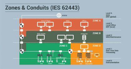
The security requirements deserve to be defined in a similar manner which is to specify protection layers and provide separation between the layers. This is because the security environment is the protecting layer which prevents security threats reaching the SIS. Befitting this concept, the zones and conduit concept is described in the international standard for automation security, IEC 62443-3-2.

A zone, in line with this standard, is a dedicated part of an overall application where identical security recommendations apply. Each zone has clearly defined perimeters and dedicated interfaces to other zones.
For each of the zones (or layers) it is necessary to define what level of security protection measures need to be implemented. These measures are the ‘foundational requirements’ of IEC 62443-3-3 and are listed as following: 1. Identification and authentication control 2. Use control 3. System integrity 4. Data confidentiality 5. Restricted data flow 6. Timely response to events 7. Resource availability
The intent is to keep the threat or risk in a zone from reaching another. Hence each zone acts as a protection layer and any interface or conduit should have enough measures to avoid any breach of security. Therefore, the BPCS, SIS, maintenance and engineering workstation and office zones should be segregated.
Any well-structured management plan for safety and security should go in tandem. Data flow requirements, interfaces and required defence systems have to be designed and built according to the International Standards IEC 61508/61511, Security Standard IEC 62443 and others. A holistic approach will address security and safety management systems, secure communication infrastructure and zones/layers capable of withstanding security breaches. For example, for an effective cyberdefence, the computer infrastructure should be set up with a secure firmware (BIOS) management, reduced access rights and with only the required Windows services activated. Portable devices should not be used as engineering stations as they can be easily moved between zones. The engineering station should be kept completely separate from other functions and the engineering station for one zone should not handle the other zones, to list just a few measures.
All devices – controllers, PCs, remote IOs and firewalls, for example – should feature an intelligent password management system and install mission specific set of application programs alone which are to be regularly updated with necessary patch management.
So, it is vital that a lifecycle management approach is taken for both security and safety. The design, realisation, operation and maintenance should all provide a management plan for security and safety. This approach should not be applicable for the industry alone – users, manufacturers, vendors and service providers also need to take responsibility for the incorporation of safety and security lifecycle management for themselves. !
Rehan Ahmad is chief operating officer at HIMA Middle East and Shafeekh Rahiman is life cycle service manager at HIMA Middle East.
DRIVE SURVEY
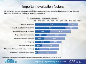
SURVEY OFFERS DRIVE ADVICE
The 2019 Control Engineering Motor Drives study asked respondents: ‘Based on your experiences and knowledge, what’s the best advice you can offer?’ Mark Hoske provides some highlights of the answers to this study.
Firstly, check for temperature rise Consider all of this with the motor’s on motor, how harmonic contents performance in light of the specific spread into the grid, and the drive that you intend to use. Failing to overall efficiency at partial load. do the pencil-work, prior to specifying
It does not matter which brand of the drive, is almost a guarantee of drives you choose for your application. disappointing performance later.
The most important factor will be the Know the application before selecting quality of the product, availability, and a drive. standardisation. Standardisation can reduce the stock of spares required and Correct drive sizing helps support personnel understand the As efficiency standards change for drives used. induction motors, watch for inrush
Know the specific details of your currents and breakdown torque and application requirements before breakdown current changes. Inrush specifying the drive. For example, know currents are rising and can cause peak velocity usage, not just average challenges with electronic overloads. velocity. Similarly, know the maximum It is important to have a thorough torque that the application demands. understanding of your application,
particularly high friction and/or high inertia starting. To get the full use of available motor torque, the drive must be correctly sized. For very large motors performing heavy-duty cycle work, be certain that the transformer and conductors do not cause large voltage drops when the application is at its greatest demand. For large hammer mills using wound rotor motors and liquid rheostats, we target <5% voltage drop at the motor at 200% full load amps (FLA). It is very common for engineers unfamiliar with the application to undersize the transformers and conductors.
Products, parts, support
Buy from someone with good technical knowledge and a lot of hands-on experience. Hire and keep good technical support people on staff.
Check compatibility before ordering, if you’re not using similar products.
Double-check specs and requirements for motor and drive selection.
Drive pricing, quality
Buy the best you can afford. Keep your equipment in good shape. All machines will break down at some point (most will do so at the worst possible time!).
Cheap equipment usually doesn’t work well, breaks down easily, and/or has bad technical support.
Do not get hung up on bells and whistles. In operation most settings tend to remain factory default and work fine.
Design, maintenance, retrofit
Don’t think you can delay or skip preventive maintenance.
Take the time to read drive manuals before installation.
Keep an open mind, standardise as much as possible, and make sure you keep up with your manuals. !
Survey managed and data compiled by Amanda Pelliccione, CFE Media and Technology research director. Edited by Mark T. Hoske, content manager, Control Engineering, CFE Media and Techology.